JP4293473B1 - Bar wire heating and cooling method and apparatus - Google Patents
Bar wire heating and cooling method and apparatus Download PDFInfo
- Publication number
- JP4293473B1 JP4293473B1 JP2008189335A JP2008189335A JP4293473B1 JP 4293473 B1 JP4293473 B1 JP 4293473B1 JP 2008189335 A JP2008189335 A JP 2008189335A JP 2008189335 A JP2008189335 A JP 2008189335A JP 4293473 B1 JP4293473 B1 JP 4293473B1
- Authority
- JP
- Japan
- Prior art keywords
- heat transfer
- tube
- fluidized bed
- cooling
- heating
- Prior art date
- Legal status (The legal status is an assumption and is not a legal conclusion. Google has not performed a legal analysis and makes no representation as to the accuracy of the status listed.)
- Expired - Fee Related
Links
Images


Abstract
【課題】 直進する棒線を連続的に流動床加熱する際、従来の浮遊流動床の持つ欠点である送風による1)熱効率低下と2)酸化性雰囲気の二問題を解消する。
【解決手段】 水平の円筒状伝熱管に熱媒体として粉粒体を装填し、該管を軸回りに回転させて転動流動床を形成する。管両端部に粉粒体の流出防止機構を組み込み、流動床を安定させる。該流動床に埋没するよう棒線を通過させる。該伝熱管を加熱すると急速加熱炉として機能し、容易に雰囲気制御でき且つ熱効率が向上する。該管を冷却すると油焼入装置として機能する。回転数により伝熱性が調節される。
【選択図】図2
PROBLEM TO BE SOLVED: To solve two problems of 1) lowering of thermal efficiency and 2) oxidizing atmosphere, which are disadvantages of a conventional floating fluidized bed, when a straight line rod is continuously heated in a fluidized bed.
A horizontal cylindrical heat transfer tube is loaded with powder particles as a heat medium, and the tube is rotated about an axis to form a rolling fluidized bed. Incorporate a mechanism to prevent the outflow of particulates at both ends of the tube to stabilize the fluidized bed. A bar is passed through to be buried in the fluidized bed. When the heat transfer tube is heated, it functions as a rapid heating furnace, the atmosphere can be easily controlled, and the thermal efficiency is improved. When the tube is cooled, it functions as an oil quenching device. Heat conductivity is adjusted by the number of rotations.
[Selection] Figure 2
Description
本発明は直進する金属、特に鋼の棒線を連続的に加熱又は冷却する方法に関している。 The present invention relates to a method for continuously heating or cooling a straight wire, in particular a steel bar.
棒線を軸方向に直進させて連続的に熱処理するに当たり、目的・内容に応じて加熱・冷却条件が設定される。加熱に際して一般に熱源から鋼材への伝熱性が大きいほど熱効率(=理論必要熱量/消費熱量)が良く、生産能率(=生産量/単位時間)の増強がやり易く、設備長さが短く、併発する酸化や脱炭など鋼材の表面品質低下の抑制に都合が良い。 Heating / cooling conditions are set according to the purpose and contents when the bar wire is linearly moved in the axial direction and continuously heat-treated. In general, the greater the heat transfer from the heat source to the steel material during heating, the better the thermal efficiency (= theoretical required heat amount / heat consumption), the easier to increase the production efficiency (= production amount / unit time), the shorter the equipment length, and the more Convenient for suppressing deterioration of surface quality of steel materials such as oxidation and decarburization.
最も汎用されている雰囲気炉や直火式加熱炉では気体と炉壁を熱媒体にして対流と放射により加熱され、総括熱伝達率αの値は約100〜200W/m2K(以後熱伝達率αの単位とする)であり、加熱能が小さい。これに比較し流動床炉ではα値は約800〜1600になって同一炉長では生産能率が大幅に強化され、近年増加傾向にある。本願発明は流動床を対象とする。 In the most atmosphere furnace or direct-fired heating furnace which is widely being heated by convection and radiation to the gas and the furnace wall to the heat medium, the value of the overall heat transfer coefficient α is about 100~200W / m 2 K (hereinafter heat transfer The unit of the rate α) and the heating ability is small. Compared with this, in the fluidized bed furnace, the α value is about 800 to 1600, and the production efficiency is greatly enhanced at the same furnace length. The present invention is directed to a fluidized bed.
流動床加熱炉では、流動砂を堆積させた槽の底部より圧縮空気を吹き込んで該砂を浮遊させて流動床を形成し、槽上方から加熱して炉としている。特徴は粉粒体の接触伝熱により伝熱性が大きいこと、浮遊混合により温度均一性が高いことである。細径製品の加熱にも又高炭素鋼線のパテンティング(約600℃の恒温変態処理)のための冷却にも使用されている。加熱に使用する際の本炉の最大の問題は、流動砂を浮遊させるための大量の送風により炉内が冷却されること、送風のため空気・燃料比を正常範囲に維持しにくいこと等により熱効率が大きく低下することである。流動床炉が伝熱性に優れるにもかかわらず最良条件下においても熱効率が25%を越えられない理由は一に送風にある。また雰囲気が必然的に酸化性であるから高温の加熱に際しては鋼材表面の酸化や脱炭を防止できず、製品によっては不都合である。 In a fluidized bed heating furnace, compressed air is blown from the bottom of a tank in which fluidized sand is deposited to float the sand to form a fluidized bed and heated from above the tank to form a furnace. The feature is that heat transfer is large due to contact heat transfer of the granular material, and temperature uniformity is high due to floating mixing. It is also used for heating small diameter products and cooling for patenting high carbon steel wires (constant temperature transformation at about 600 ° C.). The biggest problem of this furnace when using it for heating is that the inside of the furnace is cooled by a large amount of air blowing to float the fluidized sand, and it is difficult to maintain the air / fuel ratio in the normal range for air blowing. The thermal efficiency is greatly reduced. The reason why the thermal efficiency cannot exceed 25% even under the best conditions in spite of the excellent fluidity of the fluidized bed furnace is the blowing. Further, since the atmosphere is necessarily oxidizing, it is not possible to prevent oxidation or decarburization of the steel surface during high temperature heating, which is inconvenient for some products.
特許文献1には流動床炉の上記問題点を改善する方法の説明がある。即ち熱効率改善のため熱風送風等複雑な燃焼機構と温度制御機構が組み込まれている。設備が高価で作業が繁雑であるから普及していない。
流動床炉における第2の問題は、該炉を貫通する棒線の出入り口における砂の流出対策である。特許文献2にはその1例が開示されている。いずれにしろ流動砂を取り扱うには炉の構造及び作業方法に適した流出防止機構や回収・回帰機構が必要となる。
The second problem in the fluidized bed furnace is countermeasures against the outflow of sand at the entrance / exit of the bar wire penetrating the furnace.
他方冷却工程では冷却方法はあくまで対象製品の所望品質に依拠して決定され、炉冷から空冷を経て強水冷までの広範な冷却強さの中で適切な手段例えばパテンティングでは流動床冷却、焼入では油冷が選択される。
塩浴への浸漬による加熱や冷却ではα値は約1000〜2000に増加するが付着塩の飛散や洗浄等廃棄物処理の附帯設備や作業が必要になる。
鉛浴ではα値は約2000〜3000に強化されるが、重金属汚染の問題があって今後の使用は避けなければならない。
油焼入ではα値は約500〜1500であり、水焼入では上手く行かない製品に広範に使用されている。焼入油は比較的高価で且つ消耗品であるためコストが無視できないという問題がある。更に付着油が焼戻し時に不完全燃焼して悪臭を発し、公害源になる。そのため脱煙、脱臭装置等の整備が欠かせない。
On the other hand, in the cooling process, the cooling method is determined based on the desired quality of the target product. Oil cooling is selected when entering.
In heating and cooling by immersion in a salt bath, the α value increases to about 1000 to 2000, but additional facilities and work for waste treatment such as scattering and washing of adhered salt are required.
In the lead bath, the α value is enhanced to about 2000 to 3000, but there is a problem of heavy metal contamination, and future use must be avoided.
In oil quenching, the α value is about 500 to 1500, and is widely used for products that do not work well in water quenching. Since quenching oil is relatively expensive and consumable, there is a problem that the cost cannot be ignored. Furthermore, the attached oil burns incompletely during tempering and generates a bad odor, which becomes a source of pollution. Therefore, maintenance of smoke removal and deodorization equipment is indispensable.
特許文献3には、常温流動床が実質的に鉛浴焼入より大きな冷却能を持つこと、冷却能の調節は該流動床との間欠接触によってなされ、線材のパテンティングに対して極めて効果的に適用され品質は従来方法より優れると開示されている。
流動床のα値は油焼入のそれ(特定温度区間で500〜1500)と近く、原理的には常温流動床は油焼入に代替可能と見なされる。油焼入では製品に対応して適切な冷却能、適切な油種が設定される。代替させるには流動床のα値が調整可能であることが求められる。また太径成品では冷却中での酸化防止も求められる。これらの問題は未解決であり応用例は聞かれない。
In
The α value of the fluidized bed is close to that of oil quenching (500-1500 in a specific temperature interval), and in principle, the room temperature fluidized bed is considered to be replaceable with oil quenching. In oil quenching, appropriate cooling capacity and appropriate oil type are set according to the product. In order to substitute, it is required that the α value of the fluidized bed is adjustable. In addition, large diameter products are required to prevent oxidation during cooling. These problems are unresolved and no application examples are heard.
流動床では使用する砂の材質と粒度を決めるとα値はほぼ一定になり送風量や他の手段によって調節することができないという問題がある。送風量が過小であると吹き上がりが間欠的、局所的になって均等な伝熱性が得られない。過多の場合は吹き抜け現象が発生して流動が安定しない。浮遊流動を維持するには適切な送風量がある。
粒度を変更するとα値は多少変化するが粗大だと浮遊しにくくなり、微小だと排風に混入して炉外に排出される。そのため使用粒度範囲は限られる。又砂の入れ替えは煩雑であり、従ってα値の調節は実際上無理である。
In the fluidized bed, when the material and particle size of the sand to be used are determined, the α value becomes almost constant and cannot be adjusted by the amount of air blow or other means. If the blown amount is too small, the blow-up is intermittent and local, and uniform heat transfer cannot be obtained. If too much, blow-through phenomenon occurs and the flow is not stable. There is adequate air flow to maintain floating flow.
If the particle size is changed, the α value will change somewhat, but if it is coarse, it will not float easily, and if it is very small, it will be mixed into the exhaust and discharged outside the furnace. Therefore, the usable particle size range is limited. Moreover, the replacement of the sand is complicated, and therefore the adjustment of the α value is practically impossible.
鋼材の加熱冷却方法としての事例は見つからないが、応用可能性のある技術として非特許文献1に例示する回転式乾燥装置が挙げられる。ロータリーキルンと称されて非鉄金属の予備精錬や石灰の焼成等にも使用されている。該装置では回転する傾斜円筒炉内に連続的に粉粒体塊状物又はペレット状の原料が装入され、通過しつつ加熱され化学反応して排出される。その際該原料は筒内で転動流動床を形成して反応が促進される。雰囲気は火炎の調整により酸化性から還元性まで調節可能である。
No example of a method for heating and cooling a steel material has been found, but a rotary drying apparatus exemplified in Non-Patent
本発明は、直進する棒線を連続的に加熱又は冷却するに際して、急速加熱・急速冷却の一方法である流動床による伝熱の性能を最良に発揮させることを目的とする。そのためには、現行流動床の弱点である浮遊流動床を形成するための圧縮空気による送風が、炉の熱効率を低下させ、且つ雰囲気を酸化性にしている問題を解決しなければならない。さらに冷却用にも広く応用されるためには従来ほぼ一定であった伝熱性を調節可能にすることも必要である。本発明は上記問題の解決策、即ち流動床炉の熱効率を抜本向上させ、雰囲気制御を容易にし、且つ伝熱性を調節可能とする方法を提供することを課題とする。 An object of the present invention is to make the best performance of heat transfer by a fluidized bed, which is one method of rapid heating / cooling when continuously heating or cooling a straight rod. For that purpose, the problem that the ventilation by the compressed air for forming the floating fluidized bed which is a weak point of the current fluidized bed lowers the thermal efficiency of the furnace and makes the atmosphere oxidizable must be solved. Furthermore, in order to be widely applied to cooling purposes, it is also necessary to make it possible to adjust the heat transfer property that has been almost constant. It is an object of the present invention to provide a solution to the above problem, that is, a method for drastically improving the thermal efficiency of a fluidized bed furnace, facilitating atmospheric control and adjusting heat transfer.
本発明は、上記問題の解決のため流動床を形成するに当たり槽底部から圧縮空気を吹き込んで浮遊流動床を形成するという従来の方法を排する。新たに化学反応装置に使用されている回転円筒内での粉粒体の転動運動が優れた伝熱性を持つことに着眼し、該方法による新規の流動床の可能性とその効果を予備実験により確認した。さらに流動体を使用する際に避けられない流出問題に対して転動機構に連動した反転機構を組み込み、以下の発明を構成した。以後転動流動床と称する。 In order to solve the above problems, the present invention eliminates the conventional method of forming a floating fluidized bed by blowing compressed air from the bottom of the tank when forming the fluidized bed. Focusing on the excellent heat transfer in the rolling motion of the granular material in the rotating cylinder newly used in chemical reactors, the possibility of a new fluidized bed by this method and its preliminary effect Confirmed by Furthermore, a reversing mechanism linked to a rolling mechanism is incorporated for the outflow problem that cannot be avoided when using a fluid, and the following invention is configured. Hereinafter referred to as a rolling fluidized bed.
第1の発明は、軸方向に進行する金属の棒線を連続的に加熱又は冷却する伝熱方法であって、内面に多数の突起を設けた円筒状伝熱管を水平に置き、該管の内部に伝熱媒体となる流動性粉粒体を装填し、該管を中心軸の回りに回転させることにより該粉粒体を掻き上げて転動流動床を形成するとともに該管の両端部には該粉粒体の流出防止手段を設けて該流動床を持続させ、該管を加熱又は冷却して該流動床の温度を該管の温度に追随させ、直進する1本以上の棒線を該流動床に埋没するよう貫通させて加熱又は冷却することを特徴とする棒線の伝熱方法である。 A first aspect of the present invention is a heat transfer method for continuously heating or cooling a metal bar wire traveling in the axial direction, wherein a cylindrical heat transfer tube provided with a plurality of protrusions on its inner surface is placed horizontally, The inside is filled with flowable granular material that becomes a heat transfer medium, and the tube is rotated around the central axis to scoop up the granular material to form a rolling fluidized bed and at both ends of the tube Is provided with means for preventing the outflow of the granular material to maintain the fluidized bed, heating or cooling the tube to cause the temperature of the fluidized bed to follow the temperature of the tube, and It is a heat transfer method of a bar wire, which is heated or cooled by being penetrated so as to be buried in the fluidized bed.
第2の発明は、流出防止手段が、伝熱管の両端部の内面に1条以上のメスネジ状らせん溝ガイドを互いに逆向きに形成し、前記伝熱管の回転に伴い粉粒体が前記らせん溝ガイドに沿ってそれぞれ内向き(管両端の中央部へ向かう)に流動させるものであることを特徴とする第1発明に記載の棒線の伝熱方法である。 According to a second aspect of the present invention, the outflow prevention means forms one or more female screw-shaped spiral groove guides in opposite directions on the inner surfaces of both ends of the heat transfer tube, and the granular material is formed in the spiral groove as the heat transfer tube rotates. The rod wire heat transfer method according to the first aspect of the invention is characterized in that each of the wires flows inwardly (towards the center of both ends of the pipe) along the guide.
第3の発明は、流出防止手段が、伝熱管の両端面にフランジ状のダムを設けたものであることを特徴とする第1発明に記載の棒線の伝熱方法である。 According to a third aspect of the present invention, there is provided the rod wire heat transfer method according to the first aspect, wherein the outflow prevention means is provided with flange-shaped dams at both end faces of the heat transfer tube.
第4の発明は、線軸方向に直進する鋼の棒線を貫通させて連続的に加熱又は冷却する伝熱装置であって、内面に多数の突起を設け且つ両端部の内面に1条以上のメスネジ状らせん溝ガイドを互いに逆向きに形成した水平の円筒状伝熱管と、該管の内部に伝熱媒体として装填された流動性粉粒体と、該管を水平状態で中心軸の回りに回転させる駆動装置と、該管の周囲に配置され該管を加熱又は冷却する装置と、該管の両端の開口部に近接して摺動して閉鎖する棒線貫通孔を持った蓋から成ることを特徴とする棒線の伝熱装置である。 A fourth invention is a heat transfer device that continuously heats or cools through a steel rod that goes straight in the direction of the wire axis, and has a plurality of protrusions on the inner surface and one or more strips on the inner surfaces of both ends. A horizontal cylindrical heat transfer tube with female screw-shaped spiral groove guides formed in opposite directions, a flowable granular material loaded as a heat transfer medium inside the tube, and the tube in a horizontal state around the central axis A driving device for rotating, a device arranged around the tube for heating or cooling the tube, and a lid having a rod through hole that slides close to the openings at both ends of the tube and closes. It is the heat exchanger of a bar wire characterized by this.
本発明の流動床による伝熱装置は、第1に転動により流動床を形成するので従来のように浮遊流動床を形成する大量の送風を要しない。従って加熱に使用する場合、熱効率本位、設備費用本位で設計することができ比較的低設備費で加熱装置本来の熱効率が得られる。従来の25%未満に対して40%以上も可能になる。 The fluidized bed heat transfer apparatus according to the present invention first forms a fluidized bed by rolling, and thus does not require a large amount of air blowing to form a floating fluidized bed as in the prior art. Therefore, when used for heating, the design can be designed with the thermal efficiency and the equipment cost, and the original thermal efficiency of the heating apparatus can be obtained with a relatively low equipment cost. 40% or more is possible compared to the conventional less than 25%.
第2に棒線は簡単な蓋による気密状伝熱管内で加熱されるので雰囲気が酸化性になる問題を解消する。適切なガス種例えば窒素ガスや少量の水素ガスを装入した雰囲気制御がなされ精密熱処理に適する。 Secondly, since the bar wire is heated in an airtight heat transfer tube with a simple lid, the problem that the atmosphere becomes oxidizing is solved. The atmosphere is controlled with appropriate gas species such as nitrogen gas and a small amount of hydrogen gas, making it suitable for precision heat treatment.
第3に冷却に使用する場合、転動速度の調節により熱伝達率を調節することができる。油焼入で使用される種々の油種に疑似させることが容易になり、雰囲気制御と合わせて油焼入に代替させることができる。これは単にコストを低減だけではなく油焼入に不可避の悪臭公害問題を解消する。 Third, when used for cooling, the heat transfer rate can be adjusted by adjusting the rolling speed. It becomes easy to simulate various oil types used in oil quenching, and it can be replaced with oil quenching together with atmosphere control. This not only reduces costs, but also solves the problem of odor pollution that is inevitable for oil quenching.
図1(側面図)は本発明の装置を焼入焼戻しラインに応用した例の全体を説明する概略図である。処理される材料である鋼線1を直進パス2に誘導する。該パス2を内包して3本の伝熱管3、3’、3”を同軸・直列に配置し、且つ該伝熱管3、3’、3”をそれぞれ管軸回りに回転させる駆動手段4,4’により所定の速度で回転させる。具体的には図2Aに示すように伝熱管の両端部をそれぞれ2本の同方向回転の水平平行ロール(4に相当)の間に上置する。該管3,3’、3”内にはそれぞれ伝熱媒体となる粉粒体を適量装填する。回転により該粉粒体は転動流動床5を形成する。鋼線1は3段の該流動床5内を通過する。
FIG. 1 (side view) is a schematic diagram illustrating the whole of an example in which the apparatus of the present invention is applied to a quenching and tempering line. A
第1の伝熱管3はバーナー6を保有する加熱炉7内に配置される。該炉7内を約1000℃に加熱することにより、該伝熱管3が加熱され、それぞれ大きな熱伝達率のもとで該流動床5を経て該鋼線1が約950℃に加熱される。
The first
第2の伝熱管3’の上方にはスプレイ冷却装置8が配置され、回転している該管3’を冷却する。該管3’内の流動床は常温近辺に維持され進入してくる該鋼線1を油焼入と同等の熱伝達率のもとで100℃以下に冷却し焼入する。
A
第3の伝熱管3”は補助バーナー9と加熱炉7の排ガスを誘導する煙道10とを保有する加熱炉11内に配置される。煙道10は省エネルギー上採用すべきものである。該炉11は約530℃に設定され通過する鋼線1を約480℃に加熱して焼き戻す。熱処理が終わった鋼線は巻き取られてコイル12とされる。
The third
第1の伝熱管の入口と第3の伝熱管の出口に近接して摺動しつつ開口を閉鎖する蓋13(図2B)を設けて密閉状とし、所定ガスを流入させて雰囲気制御を行う。管毎に雰囲気を変えたい場合には該蓋13,13’は各管の端部にも設置する。
A lid 13 (FIG. 2B) that closes the opening while sliding close to the inlet of the first heat transfer tube and the outlet of the third heat transfer tube is provided to form a hermetic seal, and a predetermined gas is introduced to control the atmosphere. . If it is desired to change the atmosphere for each tube, the
転動流動床について詳述する。
図2は伝熱管3の要部を示す。内部に装填された粉粒体の流出を防止するため両端部には流出防止手段を設ける。該手段の適切な例として、該管3の両端部の内面にメスネジ状にらせん溝ガイド21を互いに逆向きに設ける。ねじの条数が1の場合は通常のメスネジ状、多数になるとタービン状になる。形状により作用が微妙に異なる。管3の回転により粉粒体は流動して端部で流出しようとするがらせん溝ガイド21によりねじ込まれるように戻される。他端もガイドが逆向きであるから同様にねじ込まれる。
The rolling fluidized bed will be described in detail.
FIG. 2 shows a main part of the
棒線が直進して流動床内を埋没状に通過するには、流動床の層厚さはらせん溝ガイド21の高さを越えていることが必要である。そのためにはガイド部において砂をねじ込み押し戻す作用が問題となる。押し込み作用の要因はガイド高さ、ガイド形状、ネジリード角、ガイド部長さ、回転数、ガイド条数、管内径、粉粒体の流動安息角等が関係する。最適化には試作試験により機械設計者なら特別の困難を要しない。適正条件として、十分な層厚を確保するにはらせん溝ガイド21の高さは伝熱管内半径の5%以上で30%以下が望ましい。5%未満では転動流動床が浅くなり場合により棒線が確実に埋没しないことが起こる。30%を越えるとパスレベルが上がり、対応して装填量が過剰になり、混合性が低下して流動床内の温度分布の均一性が危惧される。以下ガイド部長さは大きいほど流出が少なくなり管径以上が望ましい。
In order for the bar wire to go straight and pass through the fluidized bed in an embedded state, the layer thickness of the fluidized bed needs to exceed the height of the
該伝熱管3を管軸回りに回転すると管内に堆積されている粉粒体は内壁に沿って引き上げられるが流動性が大きいので容易に滑り、転動にはなりにくい。そこで該両端部以外の内面には伝熱フィン状の突起22を多数設ける。該突起22により粉粒体は潜り込み、掻き混ぜられ、引き上げられ、ある角度に達すると滑り落ち、速度が大きい場合には放出されるような落下も生ずる。突起高さが大きいとかき混ぜよりも掻き上げ分、放出分が増加する。突起形状と設置数は適宜修正する。例えば、突起の傾斜角や高さを種々組み合わせて混合性を強化する。潜り込みとかき混ぜによる激しい混合によって転動流動床が形成される。突起による転動とガイドによるねじ込みにより転動流動床が安定する。
When the
突起にはもう一つの機能がある。伝熱管の実効内面積の増加である。伝熱管から粉粒体への伝熱面積は装填率が関係して内面積の約50%以下に低下すると見なされる。該面積と負荷される棒線の表面積が同一と仮定すると、流動床温度は設定された炉温度(≒管体温度)と昇温又は冷却中の棒線温度との丁度中間を推移し、結局伝熱性を低下させることになる。従って実効伝熱面積比(=実効伝熱管内面積/棒線表面積)は10以上が望ましい。そのためには管径及びフィン効果を十分考慮しなければならない。内面積に対する突起表面積比の下限は掻き上げのための高さから20%以上が望ましい。上限は伝熱効果の頭打ちから100%程度でよい。過剰になると突起間の流れが低下する。 The protrusion has another function. This is an increase in the effective inner area of the heat transfer tube. The heat transfer area from the heat transfer tube to the granular material is considered to decrease to about 50% or less of the inner area due to the loading rate. Assuming that the area and the surface area of the rods to be loaded are the same, the fluidized bed temperature changes exactly between the set furnace temperature (≈ tube temperature) and the rod temperature during heating or cooling. Heat conductivity will be reduced. Therefore, the effective heat transfer area ratio (= effective heat transfer tube area / bar surface area) is preferably 10 or more. To that end, the pipe diameter and fin effect must be fully considered. The lower limit of the protrusion surface area ratio with respect to the inner area is desirably 20% or more from the height for scraping. The upper limit may be about 100% from the peak of the heat transfer effect. When it is excessive, the flow between the protrusions is lowered.
表1には温度分布に関する試算例を示す。計算条件として熱伝達率α=800、管径0.1m、棒径0.01m、実効伝熱面積比10とした。900℃に加熱するには入口部設定温度は1100℃、出口部1000℃にすればよい。実効面積比を大きくするほど、又α値を大きくするほど流動床温度は設定炉温に接近し炉温と終局棒線温度との乖離は小さくなる。冷却に対しても全く同様である。
Table 1 shows an example of a trial calculation related to the temperature distribution. The calculation conditions were heat transfer coefficient α = 800, tube diameter 0.1 m, rod diameter 0.01 m, and effective heat
粉粒体の流動強さには突起による作用だけでなく伝熱管の回転数が内径と関連して影響する。流動の増加により流動床と棒線の間の熱伝達率αが向上すると予測される。流動が過小であると層内温度が不均一になる。流動強さの目安として、運動エネルギーは内径×回転数に比例するので周速によって代用することができる。適切な量は実験で求めることが実用的である。 The flow strength of the powder is affected not only by the action of the protrusions but also by the number of rotations of the heat transfer tube in relation to the inner diameter. It is expected that the heat transfer coefficient α between the fluidized bed and the bar will be improved by increasing the flow. If the flow is too small, the temperature in the bed becomes non-uniform. As a measure of the flow strength, the kinetic energy is proportional to the inner diameter × the number of rotations, so that it can be substituted by the peripheral speed. It is practical to determine the appropriate amount experimentally.
伝熱管の材料として加熱用には耐熱鋼が使用される。熱伝導率を考慮してセラミックも使用することができる。冷却用には炭素鋼鋼管でよい。 Heat-resistant steel is used for heating as a material for the heat transfer tube. Ceramics can also be used in consideration of thermal conductivity. Carbon steel pipes may be used for cooling.
使用する粉粒体は、流動性があり凝結が起こりにくく不都合な化学反応は生じないことが条件になる。材質としてジルコン、アルミナ、珪砂、黒鉛、炭化珪素、コークス、鋼等の1種又は混合物を使用することができる。転動流動床では粉粒体の粒径は浮遊流動床のように制限されない。後者では通常0.1〜0.4mm径であるが本発明ではそれらを越えて広範な領域を使用することができる。 The granular material to be used is required to have fluidity and hardly cause agglomeration so that an undesirable chemical reaction does not occur. As a material, one or a mixture of zircon, alumina, silica sand, graphite, silicon carbide, coke, steel and the like can be used. In the rolling fluidized bed, the particle size of the granular material is not limited as in the floating fluidized bed. In the latter case, the diameter is usually 0.1 to 0.4 mm, but in the present invention, a wide range can be used beyond these.
流出防止手段の他の例を図3に示す。伝熱管3の両端面に流出防止用の環状のダム33を取付け、該ダム高さ分だけ粉粒体を装填する。鋼線31を管3の入口部で下方に案内して流動床内に埋没させる傾斜ガイド32を設ける。本手段は細径の鋼線の処理の場合に適用することができる。
Another example of the outflow prevention means is shown in FIG. An
加熱源は管の外周に配置することを原則とするが、管径が大きい場合にはロータリーキルンのように管内に配置してもよい。冷却源はスプレイ水冷を原則とする。外周に保温炉を配置して転動流動床を所定温度に制御し、塩浴冷却の代替とすることもできる。 In principle, the heating source is arranged on the outer periphery of the pipe, but when the pipe diameter is large, it may be arranged in the pipe like a rotary kiln. In principle, the cooling source is spray water cooling. It is possible to replace the salt bath cooling by arranging a heat-retaining furnace on the outer periphery to control the rolling fluidized bed to a predetermined temperature.
棒線の通し本数については特に制限はない。太径1本でもよいし線径の異なる数本を同時に通すこともできる。基本的に線径×線速=一定(値は炉長により決まる)に従い線速を決定する。その条件下では線径が異なっても炉内の同位置では同一温度になる。各種線径を混在させる操業の方が炉の加熱負荷の変動が小さくなり熱効率及び生産能率が安定する。 There is no particular limitation on the number of bar wires. One large diameter or several different diameters can be passed simultaneously. Basically, the wire speed is determined according to wire diameter × wire speed = constant (the value is determined by the furnace length). Under these conditions, even if the wire diameter is different, the same temperature is obtained at the same position in the furnace. In the operation where various wire diameters are mixed, the fluctuation of the heating load of the furnace becomes smaller and the thermal efficiency and the production efficiency are stabilized.
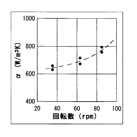
図4は試作伝熱管によって線材の冷却実験を行い回転数とα値との関係を明らかにした結果を示す。回転数の増加によりα値が増加する。これは冷却能が容易に調整し得ることを示し、例えば種々の油焼入に容易に代替させることができることを意味する。
実験条件は以下である。
FIG. 4 shows the result of clarifying the relationship between the rotational speed and the α value by conducting a wire cooling experiment using a prototype heat transfer tube. The α value increases as the rotational speed increases. This indicates that the cooling capacity can be easily adjusted, for example, it can be easily replaced by various oil quenching.
The experimental conditions are as follows.
伝熱管の構造は、内径140mm×長さ400mm、端部の流出防止としてらせん溝ガイドは1条で高さが13mm×長さ100mm、らせん溝ガイド傾斜は100/1200、転動部の突起高さは10mm×8枚/周である。閉鎖した片端を旋盤にクランプして水平回転させた。粉粒体としてジルコン砂(0.1〜0.3mm径)を容積比で約30%装填した。熱伝達率の測定にはパーカー社スマート・クエンチを使用した。これは熱電対が組み込まれた12mm径のインコネル棒を加熱炉で所定温度に加熱し、常温流動床内で冷却しつつ、温度トレースし、データを解析してα値を求めるものである。 The structure of the heat transfer tube has an inner diameter of 140 mm x length of 400 mm, and the spiral groove guide has a single strip with a height of 13 mm x length of 100 mm, the spiral groove guide slope is 100/1200, and the protrusion height of the rolling part The length is 10 mm × 8 sheets / circumference. The closed end was clamped on a lathe and rotated horizontally. Zircon sand (0.1 to 0.3 mm diameter) as a granular material was charged at a volume ratio of about 30%. Parker Smart Quench was used to measure the heat transfer rate. In this method, a 12 mm-diameter Inconel rod incorporating a thermocouple is heated to a predetermined temperature in a heating furnace, cooled in a normal temperature fluidized bed, temperature-traced, and data is analyzed to obtain an α value.
流動状況は以下である。回転と共に流出が始まる。その後押し込みと流出が均衡する。
残存した層厚は1秒1回転以上で約25〜30mmで、必ずしも十分ではないが鋼線を埋没させるには不足しない量が保持できた。冷却試験において測温センサーの棒径が大きく完全には埋没させることができなかった。そのため図示のα値は予測値より低位になっている。1秒1回転(周速0.4m/s)以上では掻き上げにより滑り、潜り込み、落下が生じて激しく混合し、均一性も問題ないことは一目瞭然である。秒速0.1回転(周速0.04m/s)程度では粉粒体の滑り落ちは続くが混合不足で転動流動床とは言い難い。
The current situation is as follows. Outflow begins with rotation. After that, pushing and outflow are balanced.
The remaining layer thickness was about 25 to 30 mm at one rotation per second or more, and although not necessarily sufficient, an amount not sufficient to embed the steel wire could be maintained. In the cooling test, the rod diameter of the temperature sensor was so large that it could not be completely buried. Therefore, the illustrated α value is lower than the predicted value. It is obvious that at one rotation per second (peripheral speed 0.4 m / s) or more, it slides, sinks, falls, mixes violently, and there is no problem with uniformity. At a speed of 0.1 rotation per second (peripheral speed 0.04 m / s), the powder particles continue to slide down, but are insufficiently mixed and difficult to call a rolling fluidized bed.
実用条件として上記観察から周速は0.1m/s以上に有ることが判明した。なお周速0では粉粒体による断熱になる。回転が過剰になると遠心鋳造のように流れも落下も無くなる。周速の上限としては管径にも関係するが滑り落ちと落下が容易に起こる範囲として2m/sと推測される。 As a practical condition, it has been found from the above observation that the peripheral speed is 0.1 m / s or more. Note that at a peripheral speed of 0, heat insulation is caused by powder particles. When the rotation becomes excessive, there is no flow and no drop like centrifugal casting. Although the upper limit of the peripheral speed is related to the pipe diameter, it is estimated that 2 m / s is the range in which slipping down and falling easily occur.
前記例において溝ガイドと突起の形状を変更して転動流動床の形成状況を観察した。溝ガイド数は1条から8条へ、ガイド・リード角は100/1600から100/100へ拡大した。観察から以下が判明した。流出防止効果が改善され残存層厚は40〜50mmに増加した。埋没させるには十分である。突起高さを小さくした効果として1秒0.5回転において掻き上げ放出は無く、潜り、掻き上げ、滑りを主とする転動現象が確認された。 In the above example, the shape of the rolling fluidized bed was observed by changing the shape of the groove guide and the protrusion. The number of groove guides increased from 1 to 8, and the guide / lead angle increased from 100/1600 to 100/100. Observations revealed the following. The outflow prevention effect was improved, and the remaining layer thickness increased to 40-50 mm. It is enough to be buried. As an effect of reducing the height of the protrusion, there was no scraping release at 0.5 rotations per second, and a rolling phenomenon mainly consisting of diving, scraping and sliding was confirmed.
上記実験装置により焼き入れ試験を行った。材料は5.5mm径の硬鋼線材(SWRH62B)を使用し、920℃に加熱後直ちに、常温の転動流動床に埋没させて常温まで冷却した。回転数は1秒1回転(周速0.4m/s)とした。金属組織の観察から断面全体がマルテンサイトであって焼入に十分な性能が有ることが確認された。 A quenching test was performed using the above experimental apparatus. As a material, a 5.5 mm diameter hard steel wire (SWRH62B) was used. Immediately after heating to 920 ° C., it was buried in a rolling fluid bed at room temperature and cooled to room temperature. The rotation speed was 1 rotation per second (peripheral speed 0.4 m / s). From the observation of the metal structure, it was confirmed that the entire cross section was martensite and had sufficient performance for quenching.
本発明を使用した細線の焼入焼戻しラインの加熱装置の設計例を表2に示す。焼入装置、焼戻し装置も全く同様に設計される。細目の検討の結果比較的簡素・コンパクト・低設備費であり実施容易であることが読みとれる。 Table 2 shows a design example of a heating device for a thin-wire quenching and tempering line using the present invention. The quenching device and the tempering device are designed in exactly the same way. As a result of the detailed examination, it can be seen that it is relatively simple, compact, and has low equipment costs and is easy to implement.
本発明の転動流動床による棒線の伝熱装置を加熱装置として使用すると、設備費が比較的低廉であること、熱効率及び品質が向上することにより既存の浮遊流動床による加熱炉に置き換えることができ、省エネルギーが得られる。各種熱処理の加熱に利用することができる。同様に冷却装置として使用すると従来の油焼入や塩浴焼入に置き換えることができ、省資源となる。銅やアルミニウムの棒線の急速加熱・急速冷却にも使用することができる。 When the rod-type heat transfer device using the rolling fluidized bed according to the present invention is used as a heating device, the equipment cost is relatively low, and the heat efficiency and quality are improved, so that the existing floating fluidized bed heating furnace is replaced. Can save energy. It can be used for heating in various heat treatments. Similarly, when used as a cooling device, it can be replaced with conventional oil quenching or salt bath quenching, thus saving resources. It can also be used for rapid heating and cooling of copper and aluminum rods.
1,31:鋼線
2:パスライン
3,3’,3”:伝熱管
4:回転駆動装置
5:転動流動床
6:バーナー
7:加熱炉
8:スプレイ冷却装置
9:補助バーナー
10:煙道
11:焼戻し炉
12:製品コイル
13,13’:蓋
21:らせん溝ガイド
22:突起
32:傾斜ガイド
33:フランジ状ダム
DESCRIPTION OF
Claims (4)
2. The rod wire heat transfer method according to claim 1, wherein the outflow prevention means is provided with annular dams on both end faces of the heat transfer tube.
A heat transfer device that continuously heats or cools through a rod that goes straight in the direction of the wire axis, and has many protrusions on the inner surface and one or more female screw-shaped spiral groove guides on the inner surfaces of both ends. A horizontal cylindrical heat transfer tube formed in the direction, a flowable granular material loaded as a heat transfer medium inside the tube, a drive device for rotating the tube around a central axis in a horizontal state, and the tube 0.2m and device for heating or cooling the tube is arranged around, Ri consists lid having bars through hole to close in proximity to the opening portions at both ends of the tube, the inner peripheral speed of the tube of / S or more, or the value of the heat transfer coefficient between the fluidized bed and the bar wire is 600 W / m 2 K or higher .
Priority Applications (1)
| Application Number | Priority Date | Filing Date | Title |
|---|---|---|---|
| JP2008189335A JP4293473B1 (en) | 2008-07-23 | 2008-07-23 | Bar wire heating and cooling method and apparatus |
Applications Claiming Priority (1)
| Application Number | Priority Date | Filing Date | Title |
|---|---|---|---|
| JP2008189335A JP4293473B1 (en) | 2008-07-23 | 2008-07-23 | Bar wire heating and cooling method and apparatus |
Publications (2)
| Publication Number | Publication Date |
|---|---|
| JP4293473B1 true JP4293473B1 (en) | 2009-07-08 |
| JP2010024512A JP2010024512A (en) | 2010-02-04 |
Family
ID=40921869
Family Applications (1)
| Application Number | Title | Priority Date | Filing Date |
|---|---|---|---|
| JP2008189335A Expired - Fee Related JP4293473B1 (en) | 2008-07-23 | 2008-07-23 | Bar wire heating and cooling method and apparatus |
Country Status (1)
| Country | Link |
|---|---|
| JP (1) | JP4293473B1 (en) |
Cited By (2)
| Publication number | Priority date | Publication date | Assignee | Title |
|---|---|---|---|---|
| JP2020143344A (en) * | 2019-03-07 | 2020-09-10 | 山田 榮子 | Fluidized bed furnace for heating and cooling steel wires |
| CN112501415A (en) * | 2020-12-07 | 2021-03-16 | 济南市东康金属制品有限公司 | Integrated heating device for producing Pc steel bar and convenient for cleaning scrap iron |
-
2008
- 2008-07-23 JP JP2008189335A patent/JP4293473B1/en not_active Expired - Fee Related
Cited By (3)
| Publication number | Priority date | Publication date | Assignee | Title |
|---|---|---|---|---|
| JP2020143344A (en) * | 2019-03-07 | 2020-09-10 | 山田 榮子 | Fluidized bed furnace for heating and cooling steel wires |
| CN112501415A (en) * | 2020-12-07 | 2021-03-16 | 济南市东康金属制品有限公司 | Integrated heating device for producing Pc steel bar and convenient for cleaning scrap iron |
| CN112501415B (en) * | 2020-12-07 | 2022-05-03 | 济南市东康金属制品有限公司 | Integrated heating device for producing Pc steel bar and convenient for cleaning scrap iron |
Also Published As
| Publication number | Publication date |
|---|---|
| JP2010024512A (en) | 2010-02-04 |
Similar Documents
| Publication | Publication Date | Title |
|---|---|---|
| JP4293473B1 (en) | Bar wire heating and cooling method and apparatus | |
| JPS63162033A (en) | Method and device for heat and/or reduction treating solid, granular and/or agglomerated charging material | |
| EA003894B1 (en) | Method for burning carbonate-containing material | |
| CN1105190C (en) | Method and appts. for heat treating steel | |
| EP1812608A1 (en) | Method and arrangement for heating extended steel products. | |
| Tsuchiya et al. | In-furnace conditions as prerequisites for proper use and design of mud to control blast furnace taphole length | |
| US3717938A (en) | Apparatus and method for drying or pre-heating pulverulent material | |
| KR101587602B1 (en) | Electric furnace for producing molten metal having material recycling capability | |
| CN105546976B (en) | A kind of grate cooler | |
| CN109477685B (en) | Melting furnace | |
| RU2376539C2 (en) | Method of heat treatment of loose materials in shaft-type furnace | |
| US3599947A (en) | Apparatus for direct iron and steel making | |
| US1924201A (en) | Apparatus for smelting aluminium and other light metals | |
| KR20010024881A (en) | Method for reducing iron oxides and installation therefor | |
| KR100738857B1 (en) | Method for purposefully moderating of pouring spout and pouring spout for performing the same | |
| CN103276167B (en) | Quenching device of circular-section granular materials | |
| RU2774680C1 (en) | Method for out-of-furnace processing of steel in a ladle | |
| US3561951A (en) | Method of feeding copper concentrates in a continuous process for smelting and converting copper concentrates to metallic copper | |
| Ubale et al. | Numerical investigation of temperature distribution in blast furnace hearth | |
| Dzurňák et al. | Impact of oxygen enhanced combustion of natural gas on thermal efficiency of combustion aggregate | |
| DE2204042C3 (en) | Process for smelting iron | |
| CN207066092U (en) | A kind of anti-oxidation heating furnace of tubular type | |
| Hadzhiyski et al. | Plasma-arc reactor for production possibility of powdered nano-size materials | |
| JP2007506063A (en) | Industrial furnace and related nozzle member | |
| RU2773348C1 (en) | Method and shaft furnace for firing a carbon-containing material therein |
Legal Events
| Date | Code | Title | Description |
|---|---|---|---|
| TRDD | Decision of grant or rejection written | ||
| A01 | Written decision to grant a patent or to grant a registration (utility model) |
Free format text: JAPANESE INTERMEDIATE CODE: A01 |
|
| FPAY | Renewal fee payment (event date is renewal date of database) |
Free format text: PAYMENT UNTIL: 20120417 |
|
| R150 | Certificate of patent or registration of utility model |
Free format text: JAPANESE INTERMEDIATE CODE: R150 |
|
| FPAY | Renewal fee payment (event date is renewal date of database) |
Free format text: PAYMENT UNTIL: 20150417 Year of fee payment: 6 |
|
| S802 | Written request for registration of partial abandonment of right |
Free format text: JAPANESE INTERMEDIATE CODE: R311802 |
|
| R350 | Written notification of registration of transfer |
Free format text: JAPANESE INTERMEDIATE CODE: R350 |
|
| R250 | Receipt of annual fees |
Free format text: JAPANESE INTERMEDIATE CODE: R250 |
|
| LAPS | Cancellation because of no payment of annual fees |