JP4291908B2 - Liquid separation device - Google Patents
Liquid separation device Download PDFInfo
- Publication number
- JP4291908B2 JP4291908B2 JP05284999A JP5284999A JP4291908B2 JP 4291908 B2 JP4291908 B2 JP 4291908B2 JP 05284999 A JP05284999 A JP 05284999A JP 5284999 A JP5284999 A JP 5284999A JP 4291908 B2 JP4291908 B2 JP 4291908B2
- Authority
- JP
- Japan
- Prior art keywords
- liquid
- chamber
- mixed
- oil
- separated
- Prior art date
- Legal status (The legal status is an assumption and is not a legal conclusion. Google has not performed a legal analysis and makes no representation as to the accuracy of the status listed.)
- Expired - Fee Related
Links
Images

Landscapes
- Production Of Liquid Hydrocarbon Mixture For Refining Petroleum (AREA)
- Cyclones (AREA)
Description
【0001】
【発明の属する技術分野】
本発明は、比重が異なりかつ相溶性のない、第1液と第2液との混合液を各液に分離して回収するようにした、混合液の分離装置に関するものである。
【0002】
【従来の技術】
従来、工作機械等により、金属ワークにカッテング等の切削加工を施すときに、そのワークの切削加工に使用される切削油(クーラント)と、工作機械自体の潤滑用に使用される潤滑油との混合油を、その切削油と、潤滑油とに分離するようにした混合液の分離装置として、たとえば実開平6−7802号公報に開示のものが知られている。
【0003】
【発明が解決しようとする課題】
ところで前記従来の混合液の分離装置は、前記混合油を、一つの分離容器内の分離板で形成される迷路を移動させ、水溶性の比重の重い切削油と、不水溶性のそれよりも比重の軽い潤滑油との比重差を利用して、それらを分離させるようにしているが、かかる分離装置では、たとえば回収して再利用される切削油の流量が、廃油となる潤滑油に比べて増量したときには、それらの分離能率が悪くなり、回収すべき切削油の回収率が低下してこれが廃油とともに廃棄されてしまうという問題がある。
【0004】
本発明はかかる事情に鑑みてなされたもので、副分離装置および主分離装置との有機的結合により、前記問題を解決した新規な混合液の分離装置を提供することを目的とするものである。
【0005】
【課題を解決するための手段】
上記目的を達成するため、本請求項1記載の発明は、水溶性の切削液である第1液と、前記切削液よりも比重の軽い不水溶性の潤滑油である第2液との混合液を、各液に分離処理するための混合液の分離装置であって、前記混合液を受け入れて、その混合液から第1液を一次的に分離する副分離装置と、前記第1液と一次分離された混合液を受け入れて、その混合液を第1液と第2液とに分離する主分離装置とを備え、前記副分離装置は、前記混合液を受け入れる混合液室と、この混合液室内の混合液より、第1、第2液の比重差により第1液を一次分離して収容する第1液室とを有し、また前記主分離装置は、第1液の一次分離された混合液を受け入れて迷路内を迂回流通させ、この混合液を、第1液と第2液との比重差により各液に緩徐に分離する主分離室と、この主分離室で分離された第1液と、前記副分離装置により一次分離された第1液とを合流収容する第1液回収室とを有することを特徴としている。
【0006】
また、上記目的達成のため、本請求項2記載の発明は、第1液と、この第1液よりも比重が軽く且つ相溶性のない第2液との混合液を、各液に分離処理するための混合液の分離装置であって、前記混合液を受け入れて、その混合液から第1液を一次的に分離する副分離装置と、前記第1液と一次分離された混合液を受け入れて、その混合液を第1液と第2液とに分離する主分離装置とを備え、前記副分離装置は、前記混合液を受け入れる混合液室と、この混合液室内の混合液より、第1、第2液の比重差により第1液を一次分離して収容する第1液室とを有し、また前記主分離装置は、第1液の一次分離された混合液を前記混合液室より受け入れて迷路内を迂回流通させ、この混合液を第1液と第2液との比重差により各液に緩徐に分離する主分離室と、この主分離室に対し横並びに配置されると共に該主分離室との間が壁で隔てられていて、前記第1液室で一次分離された第1液を前記第1液室から受け入れる第1液回収室と、前記主分離室で分離された第1液を、前記第1液回収室が前記第1液室から受入れた第1液と合流させて該第1液回収室に収容すべく、前記主分離室の下部と前記第1液回収室との相互間を常時連通させる連通路とを有することを特徴としている。
【0007】
また、上記目的達成のため、本請求項3記載の発明は、前記請求項2記載のものにおいて、前記第1液は、水溶性の切削液であり、また前記第2液は、前記切削液よりも比重の軽い不水溶性の潤滑油であることを特徴としている。
【0008】
上記請求項1,3記載の各特徴によれば、切削油と潤滑油との混合液から切削油を一次分離して流量を減じたのち、切削液の分離された混合液をさらに二次的に綿密に切削油と潤滑油とに分離させることができ、混合油の流量が多い場合でも切削油と潤滑油とを確実に分離処理して切削油の回収効率を大幅に向上させることができる。
【0009】
また上記請求項2記載の特徴によれば、第1液と第2液との混合液から第1液を一次分離して流量を減じたのち、分離された混合液をさらに第1液と第2液とに二次的に綿密に分離させることができ、混合液の流量が多い場合でも第1液と第2液とを確実に分離処理して第1液の回収効率を大幅に向上させることができる。
【0010】
【発明の実施の形態】
本発明の実施の形態を、添付図面に例示した本発明の実施例に基づいて以下に具体的に説明する。
【0011】
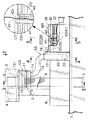
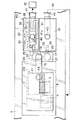
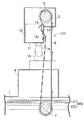
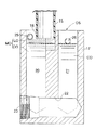
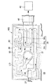
添付図面において、図1は、混合液の分離装置の全体側面図、図2は、図1の2線矢視の、混合液の分離装置の全体平面図、図3は、図1の3−3線に沿うオイルスキマーの縦断面図、図4は、図1の4−4線に沿う副分離装置の縦断面図、図5は、図1の5−5線に沿う主分離装置の縦断面図、図6は、図5の6−6線に沿う迷路ブロックの平面図である。
【0012】
図1,2において、本発明混合液の分離装置は、工作機械により、金属ワークにカッテッグ等の切削加工を施す際に使用される、水溶性の切削油(金属ワークを切削加工するときに、金属ワークとこれを切削加工するバイトの摩擦を低減して摩擦熱を除去してバイトの寿命を延長し、かつ金属ワークの加工精度をあげるために用いられる)と、不水溶性の潤滑油(工作機械自体の潤滑のために用いられる)との混合油を、各油にそれらの比重差を利用して二段階に分離すべく、副分離装置SSと主分離装置MSとより構成されており、前記副分離装置SSは、オイルスキマーOSから取り出される前記混合油MOから切削油COだけを一次的に分離するためのものであり、また主分離装置MSは、前記副分離装置SSから取り出される混合油MO(副分離装置SSにより切削油COが一次分離されている)を切削油COと潤滑油LOとに分離するためのものである。
【0013】
前記オイルスキマーOSは、切削油タンク1内に貯留される切削油COの、主として上面に浮上している、切削油COと潤滑油LOとの混合油MOを取り出して前記副分離装置SSへと導くためのものであり、従来公知のもので、本発明の要旨ではないが、本実施例の混合液の分離装置の理解を容易にするために、先ずこのオイルスキマーOSの構造およびその機能について、図1〜3を参照して簡単に説明するに、切削油タンク1上には支柱2を介してスキマー本体3が立設され、このスキマー本体3内には、モータ4により回転駆動される駆動ローラ5が設けられる。この駆動ローラ5には、布製の無端ベルト6が懸回されており、この無端ベルト6はスキマー本体3の開口下面を通って下方に垂下されて、その下端にはウエイトローラ7が懸回、吊下され、このウエイトローラ7の重力により、無端ベルト6に適度の張力が付与されている。前記無端ベルト6の下端部は、ウエイトローラ7と共に切削油タンク1内の、混合油MO内に浸漬されている。この混合油MOは工作機械から回収された、切削油COと潤滑油LOとの混合油MOであり、軽比重の潤滑油LOが重比重の切削油COの上に浮上した状態にある。そしてオイルスキマーOSの直下の、切削油タンク1の開口上面は、カバー8により被覆されている。
【0014】
スキマー本体3に一体のブラケット10を介してスクレーパケース11が固着され、このスクレーパケース11内に、前記無端ベルト6の緩み側の一部が通過できるようになっており、この無端ベルト6の緩み側の内、外面に、スクレーパケース11に設けた内側スクレーパ13および外側スクレーパ121 ,122 のエッジ部分がそれぞれ当接されていて、無端ベルト6が作動されるとき、これらのスクレーパ13,121 ,122 により、無端ベルト6に付着した混合油MOを掻き落とせるようになっている。スクレーパケース11の下部には、排出口14が開口されており、この排出口14は、取出パイプ15に連通され、この取出パイプ15の下端は、後に詳述する副分離タンク17の入口18に連通されている。
【0015】
ウエイトローラ7を吊下している無端ベルト6の下端部を、切削油タンク1に回収されている、その切削油COと潤滑油LOとの混合油MO(軽比重の潤滑油LOが、重比重の切削油CO上に浮上している)中に浸漬させたのち、モータ4の駆動により駆動ローラ5を回転すれば、混合油MO、主としてその上面に浮上している浮上油が無端ベルト6の表裏両面に付着したままスクレーパケース11内に持ち上げられ、ここで内側および外側スクレーパ13および121 ,122 によりその付着油が掻き落とされて排出口14より取出パイプ15を経て副分離装置SSへと流れる。
【0016】
なお、オイルスキマーOSは従来公知のものが使用され、前記構造のものでなくてもよい。
【0017】
副分離装置SSは、オイルスキマーOSから取り出された混合油MOより切削油COだけを一次的に分離する機能をもつものであり、以下に、この副分離装置SSの構成を図1,2および図4を参照して説明するに、この副分離装置SSの主体部を構成する副分離タンク17は、偏平な角筒状に形成されていて、その上面の一側に開口される入口18には、前記取出パイプ15の下端が連通接続される。副分離タンク17内には、何れも円筒状の上下に細長い、混合液室としての混合油室20と、第1液室としての一次切削油室21とが並設されており、混合油室20の上部に前記入口18が開口されて前記取出パイプ15が連通され、また一次切削油室21の上面は大気に開口されている。混合油室20と一次切削油室21とは、副分離タンク17の底部に横方向に形成した連絡通路22を介して相互に連通されており、この連絡通路22の開口端は盲栓23により封緘されている。混合油室20の上部には、混合油排出口25が開口され、また一次切削油室21の上部には、前記混合油排出口25よりも低いレベルで切削油排出口26が開口されている。混合油排出口25は連通パイプ27を経て後述する主分離装置MSの主分離室32に連通され、また切削油排出口26は連通パイプ28を経て後述する主分離装置MSの、第1液回収室としての切削油回収室33に連通されている。
【0018】
オイルスキマーOSから取り出された混合油MOは、取出パイプ15より混合油室20に流入し、さらに連絡通路22を通って一次切削油室21にも流入する。
【0019】
ところでこの副分離装置SSでは、混合油MOから切削油COだけを一次分離すると共に後述する主分離装置MSへ導入される混合油MOの流量を調節する機能をもつものであり、切削油COと潤滑油LOとの混合油MOに比べて比重の重い切削油COは、その混合油MOから分離されて一次切削油室26に流れ、そこに開口した、低いレベルの切削油排出口21より排出されて後述する主分離装置MSへと導かれ、また切削油COよりも比重の軽い混合油MOは、高いレベルの混合油排出口25より排出されて後述する主分離装置MSへと導かれる。
【0020】
次に主分離装置MSは、副分離装置SSで切削油COの一次分離された混合油MOを、さらに切削油COと潤滑油LOとに時間をかけて二次的に分離すると共に一次、二次分離された切削油COを合流させて貯留する機能をもつものであり、以下にこの主分離装置MSの構成を、図1,2および図5,6を参照して説明するに、主分離装置MSの主体部を構成する主分離タンク30は、上面の開口された角筒状に形成されている。主分離タンク30は、その中央部に縦方向に設けられる仕切壁31により主分離室32と、第1液回収室としての切削油回収室33とに仕切られている。前記仕切壁31の下端は主分離室32の底壁には達しておらず、その下方には主分離室32と切削油回収室33とを連通する連通路34が形成されており、主分離室32に流入した混合油MO(副分離装置SSにより切削油が一次分離されている)のうち、比重の重い水溶性の切削油COのみが潤滑油LOから分離してこの連通路34を通って切削油回収室33へと流入するようになっている。また主分離室32の一側には副分離装置SSの混合油排出口25に連通する入口35が開口され、また切削油回収室33の一側には副分離装置SSの切削油排出口26に連通する入口36が開口されている。
【0021】
図6に明瞭に示すように、主分離室32の上部には、その開口上面を塞ぐようにして四角板状の迷路ブロック38が固着されている。この迷路ブロック38は、この主分離室32に流入した混合油MOを、時間をかけて切削油COと潤滑油LOとに二次的に確実に分離する機能をもつものであり、その上下面に開口する迷路39が形成されている。この迷路39は、その道のりが長くなるようにその全面にわたり迂回して形成されていて、その迷路ブロック38の長手方向の一側に沿って延びる直線状通路391 、それに続くクランク状通路392 さらにそれに続いて前記直線通路391 と並列するジグザク状通路393 とよりなり、前記直線状通路391 の上流端が前記入口35に連通され、またジグザグ状通路393 の下流端が、迷路ブロック38の中央部に開口した出口40に連通されている。また主分離室32の他側には廃油(潤滑油)回収パイプ41が接続されている。この廃油回収パイプ41は、主分離室32内に進入しており、その端部が上向きに湾曲していて、その入口411 が主分離室32の略中央部において上向きに開口していて、前記迷路39の出口40に接続されている。そして廃油回収パイプ41の入口411 は、迷路ブロック38の上面近くに開口しており、迷路ブロック38により分離された、軽比重の潤滑油LOすなわち廃油を回収できるようになっている。
【0022】
副分離装置SSから主分離室32内の迷路ブロック38に流入した混合油MOは、その迷路39内をその上流側から下流側へと時間をかけてゆっくりと流れ、その間に図5に示すように比重の軽い不水溶性の潤滑油LOは上層に、またそれよりも比重の重い水溶性の切削油COが下層になって、二層にくっきりと分離される。そして軽比重の廃油となる潤滑油LOは、前述したように、廃油回収パイプ41を通って外部に流れて廃油タンク42に貯留される。
【0023】
一方重比重の切削油COは、廃油回収パイプ41の入口411 よりも低位にあり、その入口411 に流入することなく、主分離室32の迷路ブロック38下に溜まり、さらにそこから連通路34を通って切削油回収室33側へと流れる。而して切削油回収室33の他側には切削油回収パイプ43が接続されている。この切削油回収パイプ43は、切削油回収室33の中央部まで延びており、その端部が上向に湾曲してその入口431 は上向きに開口している。図5に明瞭に示すように、この切削油回収パイプ43の入口431 のレベルは、前記廃油回収パイプ41の入口411 のレベルよりも低位にあり、潤滑油LOよりも比重の重い切削油COは切削油回収パイプ43へと流れ、回収回路44を経て前記切削油タンク1に回収されるようになっている。
【0024】
以上のように、切削油回収室33には、前記副分離装置SSにより一次分離された切削油COと、主分離装置MSより二次分離された切削油COとが合流して貯留される。そしてその回収切削油COは回収回路44を経て切削タンク1へと還流されて再度工作機械の金属ワークの切削加工用の切削油として再使用される。
【0025】
かくして、オイルスキマーOSから取り出された、切削油COと潤滑油LOとの混合油MOは、副分離装置SSで切削油COが一次的に分離され、さらに主分離装置MSで切削油COの一次分離された混合油MOを切削油COと潤滑油LOとに二次的に分離することができ、結局切削油COは、混合油MOから2段階に分離され、再度切削油タンク1に戻されて工作機械のカッテング等の機械加工作業に使用することができ、また分離された潤滑油LOは、廃油として焼却処理される。
【0026】
以上、本発明の実施例について説明したが、本発明はその実施例に限定されることなく、本発明の範囲内で種々の実施例が可能である。
【0027】
たとえば前記実施例では、第1液を水溶性の切削油、第2液を不水溶性の潤滑油として、それらの混合液の分離装置として説明したが、本発明(特に請求項2の発明)は互いに相溶性がなく、かつ比重の異なる他の二液の混合液の分離処理にも実施できることは勿論である。
【0028】
【発明の効果】
以上のように本請求項1,3記載の各発明によれば、切削油と潤滑油との混合液の分離装置において、切削油と潤滑油との混合液から切削油を一次分離して流量を減じてのち、分離された混合液をさらに二次的に綿密に切削油と潤滑油とに分離させることができ、混合油の流量が多い場合でも切削油から潤滑油を確実に分離処理して切削油の回収効率を大幅に向上させることができる。
【0029】
また、本請求項2記載の発明によれば、第1液と、この第1液よりも比重が軽く且つ相溶性のない第2液との混合液の分離装置において、第1液と第2液との混合液から第1液を一次分離して流量を減じたのち、第1液の分離された混合液をさらに第1液と第2液とに二次的に綿密に分離させることができ、混合液の流量が多い場合でも第1液と第2液とを確実に分離処理し、その結果、第1液の回収効率を大幅に向上させることができる。
【図面の簡単な説明】
【図1】 混合液の分離装置の全体側面図
【図2】 図1の2線矢視の、混合液の分離装置の全体平面図
【図3】 図1の3−3線に沿うオイルスキマーの縦断面図
【図4】 図1の4−4線に沿う副分離装置の縦断面図
【図5】 図1の5−5線に沿う主分離装置の縦断面図
【図6】 図5の6−6線に沿う迷路ブロックの平面図
【符号の説明】
20・・・・混合液室(混合油室)
21・・・・第1液室(一次切削油室)
32・・・・主分離室
33・・・・第1液回収室(切削油回収室)
39・・・・迷路
MO・・・・混合液(混合油)
CO・・・・第1液(切削油)
LO・・・・第2液(潤滑油)
OS・・・・オイルスキマー
SS・・・・副分離装置
MS・・・・主分離装置[0001]
BACKGROUND OF THE INVENTION
The present invention relates to a mixed liquid separation apparatus in which a mixed liquid of a first liquid and a second liquid having different specific gravities and no compatibility is separated and recovered.
[0002]
[Prior art]
Conventionally, when a cutting work such as cutting is performed on a metal workpiece by a machine tool or the like, a cutting oil (coolant) used for cutting the workpiece and a lubricating oil used for lubricating the machine tool itself are used. As an apparatus for separating a mixed liquid in which the mixed oil is separated into its cutting oil and lubricating oil, for example, one disclosed in Japanese Utility Model Laid-Open No. 6-7802 is known.
[0003]
[Problems to be solved by the invention]
By the way, the conventional apparatus for separating a mixed liquid moves the mixed oil through a maze formed by a separation plate in one separation container, so that the water-soluble heavy cutting oil and the water-insoluble one can be used. They are separated using a specific gravity difference with a lighter specific gravity, but in such a separation device, for example, the flow rate of the cutting oil that is recovered and reused is higher than that of the lubricating oil that becomes waste oil. When the amount is increased, their separation efficiency deteriorates, the recovery rate of the cutting oil to be recovered decreases, and this is discarded together with the waste oil.
[0004]
The present invention has been made in view of such circumstances, and an object of the present invention is to provide a novel mixed liquid separation apparatus that solves the above problems by organic coupling with a sub-separation apparatus and a main separation apparatus. .
[0005]
[Means for Solving the Problems]
To achieve the above object, the invention of this claim 1, wherein the mixing of the first liquid is a water-soluble cutting fluid, a second fluid than the cutting fluid is lighter, water-insoluble lubricant of specific gravity A separation device for a mixed liquid for separating the liquid into each liquid, the sub-separation device that receives the mixed liquid and primarily separates the first liquid from the mixed liquid, and the first liquid, A main separation device that receives the first separated liquid mixture and separates the mixed liquid into a first liquid and a second liquid, and the sub-separation device includes a liquid mixture chamber that receives the liquid mixture, and the mixing liquid chamber. A first liquid chamber that primarily separates and stores the first liquid from the mixed liquid in the liquid chamber based on a difference in specific gravity between the first and second liquids, and the main separator is primarily separated from the first liquid. The mixed liquid is received and circulated in the maze, and this mixed liquid is gradually separated into each liquid due to the difference in specific gravity between the first liquid and the second liquid. Have a main separation chamber for separating a first liquid separated by the main separation chamber, that has a first liquid recovery chamber merging housing the first liquid is primarily separated by the secondary separating device is characterized .
[0006]
Further, in order to achieve the above object, the invention according to
[0007]
In order to achieve the above object, the invention described in
[0008]
According to each feature of the first and third aspects, after the cutting oil is primarily separated from the mixed liquid of the cutting oil and the lubricating oil to reduce the flow rate, the mixed liquid from which the cutting liquid is separated is further secondary It is possible to separate the cutting oil and the lubricating oil closely, and even when the flow rate of the mixed oil is large, the cutting oil and the lubricating oil can be reliably separated to greatly improve the cutting oil recovery efficiency. .
[0009]
Further, according to the feature of the second aspect, after the first liquid is primarily separated from the liquid mixture of the first liquid and the second liquid to reduce the flow rate, the separated liquid mixture is further separated from the first liquid and the first liquid. The second liquid can be secondarily closely separated, and even when the flow rate of the mixed liquid is large, the first liquid and the second liquid are reliably separated to greatly improve the recovery efficiency of the first liquid. be able to.
[0010]
DETAILED DESCRIPTION OF THE INVENTION
Embodiments of the present invention will be specifically described below based on the embodiments of the present invention illustrated in the accompanying drawings.
[0011]
In the accompanying drawings, FIG. 1 is an overall side view of a mixed liquid separating apparatus, FIG. 2 is an overall plan view of the mixed liquid separating apparatus as viewed in the direction of the
[0012]
In FIGS. 1 and 2, the separator of the present invention is a water-soluble cutting oil (when cutting a metal workpiece, used when cutting a metal workpiece with a cutting tool or the like by a machine tool. Used to reduce friction between metal workpiece and cutting tool to remove frictional heat and extend tool life, and improve machining accuracy of metal workpiece) and water-insoluble lubricant ( It is composed of sub-separator SS and main separator MS in order to separate the mixed oil with each oil into two stages using the difference in specific gravity of each oil. The sub-separation device SS is for temporarily separating only the cutting oil CO from the mixed oil MO taken out from the oil skimmer OS, and the main separation device MS is taken out from the sub-separation device SS. Mixed oil O (cutting oil CO by secondary separating device SS are primary separation) is for separating into a cutting oil CO and lubricating oil LO.
[0013]
The oil skimmer OS takes out the mixed oil MO of the cutting oil CO stored in the cutting oil tank 1 and floating mainly on the upper surface of the cutting oil CO and the lubricating oil LO, and supplies it to the sub-separator SS. The structure of the oil skimmer OS and its function are first described in order to facilitate understanding of the mixed liquid separation apparatus of the present embodiment. 1 to 3, a
[0014]
A
[0015]
The lower end portion of the
[0016]
The oil skimmer OS may be a conventionally known one and may not have the above structure.
[0017]
The sub-separator SS has a function of primarily separating only the cutting oil CO from the mixed oil MO taken out from the oil skimmer OS, and the configuration of the sub-separator SS will be described below with reference to FIGS. As will be described with reference to FIG. 4, the
[0018]
The mixed oil MO taken out from the oil skimmer OS flows into the
[0019]
By the way, this sub-separator SS has a function of primarily separating only the cutting oil CO from the mixed oil MO and adjusting the flow rate of the mixed oil MO introduced into the main separator MS described later. The cutting oil CO having a higher specific gravity than the mixed oil MO with the lubricating oil LO is separated from the mixed oil MO, flows into the primary cutting
[0020]
Next, the main separation device MS further separates the mixed oil MO, which has been primarily separated by the sub-separation device SS, into the cutting oil CO and the lubricating oil LO over time, and then separates the mixed oil MO first and second. The next separated cutting oil CO has a function of joining and storing, and the configuration of the main separation device MS will be described below with reference to FIGS. The
[0021]
As clearly shown in FIG. 6, a square plate-
[0022]
The mixed oil MO that has flowed into the
[0023]
On the other hand, the cutting fluid CO having a specific gravity is lower than the
[0024]
As described above, in the cutting
[0025]
Thus, the mixed oil MO of the cutting oil CO and the lubricating oil LO extracted from the oil skimmer OS is primarily separated from the cutting oil CO by the sub-separator SS, and further the primary oil cutting oil CO by the main separator MS. The separated mixed oil MO can be secondarily separated into the cutting oil CO and the lubricating oil LO. After all, the cutting oil CO is separated into two stages from the mixed oil MO and returned to the cutting oil tank 1 again. The lubricating oil LO can be used for machining operations such as cutting of machine tools, and the separated lubricating oil LO is incinerated as waste oil.
[0026]
As mentioned above, although the Example of this invention was described, this invention is not limited to the Example, A various Example is possible within the scope of the present invention.
[0027]
For example, in the above embodiment, the first liquid is used as a water-soluble cutting oil, and the second liquid is used as a water-insoluble lubricating oil. However, the present invention (particularly the invention of claim 2) is described as a mixed liquid separation device. Needless to say, can also be applied to the separation treatment of a mixed solution of two other liquids which are not compatible with each other and have different specific gravities.
[0028]
【The invention's effect】
According to the above so that each invention in the
[0029]
According to the second aspect of the present invention, in the separation apparatus for the mixed liquid of the first liquid and the second liquid having a lighter specific gravity than the first liquid and having no compatibility, the first liquid and the second liquid are separated. After first separating the first liquid from the liquid mixture with the liquid and reducing the flow rate, the liquid mixture separated from the first liquid can be further separated into the first liquid and the second liquid secondarily and closely. Even when the flow rate of the mixed liquid is large, the first liquid and the second liquid can be reliably separated, and as a result, the recovery efficiency of the first liquid can be greatly improved.
[Brief description of the drawings]
FIG. 1 is an overall side view of a mixed liquid separating apparatus. FIG. 2 is an overall plan view of a mixed liquid separating apparatus as viewed in the direction of the
20 .... Mixed liquid chamber (mixed oil chamber)
21... First liquid chamber (primary cutting oil chamber)
32 ...
39 ... Maze MO ... Mixed liquid (mixed oil)
CO ··· First liquid (cutting oil)
LO ··· Second liquid (lubricating oil)
OS ... Oil skimmer SS ... Subseparator MS ... Main separator
Claims (3)
前記混合液(MO)を受け入れて、その混合液(MO)から第1液(CO)を一次的に分離する副分離装置(SS)と、
前記第1液(CO)と一次分離された混合液(MO)を受け入れて、その混合液(MO)を第1液(CO)と第2液(LO)とに分離する主分離装置(MS)とを備え、
前記副分離装置(SS)は、前記混合液(MO)を受け入れる混合液室(20)と、この混合液室(20)内の混合液(MO)より、第1、第2液(CO,LO)の比重差により第1液(CO)を一次分離して収容する第1液室(21)とを有し、
また前記主分離装置(MS)は、第1液(CO)の一次分離された混合液(MO)を受け入れて迷路(39)内を迂回流通させ、この混合液(MO)を、第1液(CO)と第2液(LO)との比重差により各液(CO,LO)に緩徐に分離する主分離室(32)と、この主分離室(32)で分離された第1液(CO)と、前記副分離装置(SS)により一次分離された第1液(CO)とを合流収容する第1液回収室(33)とを有することを特徴とする、混合液の分離装置。The first liquid is a water-soluble cutting fluid with (CO), the mixed liquid of the second liquid than cutting fluid is lighter, water-insoluble lubricant of specific gravity (LO) and (MO), each liquid (CO , LO), a liquid separation device for separation treatment,
A sub-separator (SS) that receives the liquid mixture (MO) and primarily separates the first liquid (CO) from the liquid mixture (MO);
A main separation device (MS) that receives the mixed liquid (MO) primarily separated from the first liquid (CO) and separates the mixed liquid (MO) into a first liquid (CO) and a second liquid (LO). ) and equipped with a,
The sub-separator (SS) includes a liquid mixture chamber (20) that receives the liquid mixture (MO), and a liquid mixture (MO) in the liquid mixture chamber (20). (LO) having a first liquid chamber (21) that primarily separates and stores the first liquid (CO) due to a difference in specific gravity.
The main separation device (MS) receives the first separated liquid mixture (MO) (MO) and circulates in the labyrinth (39). The mixed liquid (MO) is passed through the first liquid (MO). A main separation chamber (32) that slowly separates into each liquid (CO, LO) due to a difference in specific gravity between the (CO) and the second liquid (LO), and a first liquid separated in the main separation chamber (32) ( A mixed liquid separation device, comprising: a first liquid recovery chamber (33) for merging and storing (CO) and the first liquid (CO) primarily separated by the sub-separation device (SS).
前記混合液(MO)を受け入れて、その混合液(MO)から第1液(CO)を一次的に分離する副分離装置(SS)と、A sub-separator (SS) that receives the liquid mixture (MO) and primarily separates the first liquid (CO) from the liquid mixture (MO);
前記第1液(CO)と一次分離された混合液(MO)を受け入れて、その混合液(MO)を第1液(CO)と第2液(LO)とに分離する主分離装置(MS)とを備え、A main separation device (MS) that receives the mixed liquid (MO) primarily separated from the first liquid (CO) and separates the mixed liquid (MO) into a first liquid (CO) and a second liquid (LO). )
前記副分離装置(SS)は、The sub-separator (SS)
前記混合液(MO)を受け入れる混合液室(20)と、A liquid mixture chamber (20) for receiving the liquid mixture (MO);
この混合液室(20)内の混合液(MO)より、第1、第2液(CO,LO)の比重差により第1液(CO)を一次分離して収容する第1液室(21)とを有し、The first liquid chamber (21) that primarily separates and stores the first liquid (CO) from the mixed liquid (MO) in the mixed liquid chamber (20) by the specific gravity difference between the first and second liquids (CO, LO). )
前記主分離装置(MS)は、The main separator (MS)
第1液(CO)の一次分離された混合液(MO)を前記混合液室(20)より受け入れて迷路(39)内を迂回流通させ、この混合液(MO)を第1液(CO)と第2液(LO)との比重差により各液(CO,LO)に緩徐に分離する主分離室(32)と、The first separated liquid mixture (MO) is firstly received from the mixed liquid chamber (20) and is circulated in the labyrinth (39), and the mixed liquid (MO) is passed through the first liquid (CO). A main separation chamber (32) that slowly separates into each liquid (CO, LO) due to the specific gravity difference between the second liquid (LO) and
この主分離室(32)に対し横並びに配置されると共に該主分離室(32)との間が壁(31)で隔てられていて、前記第1液室(21)で一次分離された第1液(CO)を前記第1液室(21)から受け入れる第1液回収室(33)と、The main separation chamber (32) is arranged side by side and is separated from the main separation chamber (32) by a wall (31), and is first separated in the first liquid chamber (21). A first liquid recovery chamber (33) for receiving one liquid (CO) from the first liquid chamber (21);
前記主分離室(32)で分離された第1液(CO)を、前記第1液回収室(33)が前記第1液室(21)から受入れた第1液(CO)と合流させて該第1液回収室(33)に収容すべく、前記主分離室(32)の下部と前記第1液回収室(33)との相互間を常時連通させる連通路(34)とを有することを特徴とする、混合液の分離装置。The first liquid (CO) separated in the main separation chamber (32) is joined with the first liquid (CO) received by the first liquid recovery chamber (33) from the first liquid chamber (21). In order to accommodate in the first liquid recovery chamber (33), there is provided a communication path (34) for always communicating between the lower part of the main separation chamber (32) and the first liquid recovery chamber (33). An apparatus for separating a mixed liquid, characterized by
Priority Applications (1)
| Application Number | Priority Date | Filing Date | Title |
|---|---|---|---|
| JP05284999A JP4291908B2 (en) | 1999-03-01 | 1999-03-01 | Liquid separation device |
Applications Claiming Priority (1)
| Application Number | Priority Date | Filing Date | Title |
|---|---|---|---|
| JP05284999A JP4291908B2 (en) | 1999-03-01 | 1999-03-01 | Liquid separation device |
Publications (2)
| Publication Number | Publication Date |
|---|---|
| JP2000246006A JP2000246006A (en) | 2000-09-12 |
| JP4291908B2 true JP4291908B2 (en) | 2009-07-08 |
Family
ID=12926309
Family Applications (1)
| Application Number | Title | Priority Date | Filing Date |
|---|---|---|---|
| JP05284999A Expired - Fee Related JP4291908B2 (en) | 1999-03-01 | 1999-03-01 | Liquid separation device |
Country Status (1)
| Country | Link |
|---|---|
| JP (1) | JP4291908B2 (en) |
Families Citing this family (5)
| Publication number | Priority date | Publication date | Assignee | Title |
|---|---|---|---|---|
| JP5430286B2 (en) * | 2009-08-13 | 2014-02-26 | 三菱電機エンジニアリング株式会社 | Oil / water separator |
| JP6397392B2 (en) * | 2015-10-15 | 2018-09-26 | 群馬精工株式会社 | Machining fluid performance recovery system |
| JP2017113875A (en) * | 2015-12-18 | 2017-06-29 | いすゞ自動車株式会社 | Oil recovery apparatus |
| JP6870387B2 (en) * | 2017-03-01 | 2021-05-12 | いすゞ自動車株式会社 | Oil recovery device |
| JP7119318B2 (en) * | 2017-09-14 | 2022-08-17 | いすゞ自動車株式会社 | Oil recovery device |
-
1999
- 1999-03-01 JP JP05284999A patent/JP4291908B2/en not_active Expired - Fee Related
Also Published As
| Publication number | Publication date |
|---|---|
| JP2000246006A (en) | 2000-09-12 |
Similar Documents
| Publication | Publication Date | Title |
|---|---|---|
| JPH0326082B2 (en) | ||
| JP3546359B2 (en) | Oil-water separator | |
| US5066407A (en) | Petrochemical recovery machine | |
| SE9902914L (en) | Apparatus for collecting liquid contaminants on the surface of a body of water, as well as flow recipient for use in such collection | |
| JP3399287B2 (en) | Spilled oil recovery equipment | |
| WO1999034894A1 (en) | Apparatus for separating a low density liquid from a high density liquid | |
| JP4392814B2 (en) | Oil / water separator | |
| CN209721751U (en) | Nylon chips production removes system with river silt | |
| US5522990A (en) | Oil removal device with integrated gravity separator | |
| CN110404672A (en) | Liquid cleaning device and purification method and water tank with the device | |
| JP2001137743A (en) | Apparatus for cleaning and recovering coolant | |
| JP2000246006A (en) | Mixture separation equipment | |
| KR100212164B1 (en) | Oil-water recovering and separating apparatus | |
| US4521313A (en) | Fluid purification system | |
| CN209161627U (en) | A kind of kitchen mo(u)ld bottom half oil-water separator | |
| JP4439845B2 (en) | Float collection device | |
| JPH02218535A (en) | Cutting oil recovery device | |
| JP2939426B2 (en) | Oil-water separation equipment | |
| CN212347807U (en) | Oil-water separation device with flow adjusting function | |
| CN209367983U (en) | A kind of oil separator | |
| CA1168991A (en) | Topological separator | |
| JP5099734B2 (en) | Liquid mixture separator | |
| CN201175596Y (en) | Automatic oil-water separator | |
| JP3546360B2 (en) | Organic solvent separator | |
| JP3144626B2 (en) | Oil-water separation equipment |
Legal Events
| Date | Code | Title | Description |
|---|---|---|---|
| A621 | Written request for application examination |
Free format text: JAPANESE INTERMEDIATE CODE: A621 Effective date: 20051229 |
|
| A131 | Notification of reasons for refusal |
Free format text: JAPANESE INTERMEDIATE CODE: A131 Effective date: 20081119 |
|
| A521 | Written amendment |
Free format text: JAPANESE INTERMEDIATE CODE: A523 Effective date: 20090119 |
|
| TRDD | Decision of grant or rejection written | ||
| A01 | Written decision to grant a patent or to grant a registration (utility model) |
Free format text: JAPANESE INTERMEDIATE CODE: A01 Effective date: 20090325 |
|
| A01 | Written decision to grant a patent or to grant a registration (utility model) |
Free format text: JAPANESE INTERMEDIATE CODE: A01 |
|
| A61 | First payment of annual fees (during grant procedure) |
Free format text: JAPANESE INTERMEDIATE CODE: A61 Effective date: 20090406 |
|
| R150 | Certificate of patent or registration of utility model |
Free format text: JAPANESE INTERMEDIATE CODE: R150 |
|
| FPAY | Renewal fee payment (event date is renewal date of database) |
Free format text: PAYMENT UNTIL: 20120410 Year of fee payment: 3 |
|
| FPAY | Renewal fee payment (event date is renewal date of database) |
Free format text: PAYMENT UNTIL: 20130410 Year of fee payment: 4 |
|
| LAPS | Cancellation because of no payment of annual fees |