JP4291689B2 - Multiwell plate with heat storage around - Google Patents
Multiwell plate with heat storage around Download PDFInfo
- Publication number
- JP4291689B2 JP4291689B2 JP2003503357A JP2003503357A JP4291689B2 JP 4291689 B2 JP4291689 B2 JP 4291689B2 JP 2003503357 A JP2003503357 A JP 2003503357A JP 2003503357 A JP2003503357 A JP 2003503357A JP 4291689 B2 JP4291689 B2 JP 4291689B2
- Authority
- JP
- Japan
- Prior art keywords
- wells
- plate
- sample
- planar member
- chamber
- Prior art date
- Legal status (The legal status is an assumption and is not a legal conclusion. Google has not performed a legal analysis and makes no representation as to the accuracy of the status listed.)
- Expired - Fee Related
Links
Images


Classifications
-
- B—PERFORMING OPERATIONS; TRANSPORTING
- B01—PHYSICAL OR CHEMICAL PROCESSES OR APPARATUS IN GENERAL
- B01L—CHEMICAL OR PHYSICAL LABORATORY APPARATUS FOR GENERAL USE
- B01L3/00—Containers or dishes for laboratory use, e.g. laboratory glassware; Droppers
- B01L3/50—Containers for the purpose of retaining a material to be analysed, e.g. test tubes
- B01L3/508—Containers for the purpose of retaining a material to be analysed, e.g. test tubes rigid containers not provided for above
- B01L3/5085—Containers for the purpose of retaining a material to be analysed, e.g. test tubes rigid containers not provided for above for multiple samples, e.g. microtitration plates
- B01L3/50851—Containers for the purpose of retaining a material to be analysed, e.g. test tubes rigid containers not provided for above for multiple samples, e.g. microtitration plates specially adapted for heating or cooling samples
-
- C—CHEMISTRY; METALLURGY
- C12—BIOCHEMISTRY; BEER; SPIRITS; WINE; VINEGAR; MICROBIOLOGY; ENZYMOLOGY; MUTATION OR GENETIC ENGINEERING
- C12M—APPARATUS FOR ENZYMOLOGY OR MICROBIOLOGY; APPARATUS FOR CULTURING MICROORGANISMS FOR PRODUCING BIOMASS, FOR GROWING CELLS OR FOR OBTAINING FERMENTATION OR METABOLIC PRODUCTS, i.e. BIOREACTORS OR FERMENTERS
- C12M23/00—Constructional details, e.g. recesses, hinges
- C12M23/02—Form or structure of the vessel
- C12M23/12—Well or multiwell plates
-
- C—CHEMISTRY; METALLURGY
- C12—BIOCHEMISTRY; BEER; SPIRITS; WINE; VINEGAR; MICROBIOLOGY; ENZYMOLOGY; MUTATION OR GENETIC ENGINEERING
- C12M—APPARATUS FOR ENZYMOLOGY OR MICROBIOLOGY; APPARATUS FOR CULTURING MICROORGANISMS FOR PRODUCING BIOMASS, FOR GROWING CELLS OR FOR OBTAINING FERMENTATION OR METABOLIC PRODUCTS, i.e. BIOREACTORS OR FERMENTERS
- C12M41/00—Means for regulation, monitoring, measurement or control, e.g. flow regulation
- C12M41/12—Means for regulation, monitoring, measurement or control, e.g. flow regulation of temperature
- C12M41/16—Means for regulation, monitoring, measurement or control, e.g. flow regulation of temperature by recirculation of culture medium at controlled temperature
-
- B—PERFORMING OPERATIONS; TRANSPORTING
- B01—PHYSICAL OR CHEMICAL PROCESSES OR APPARATUS IN GENERAL
- B01L—CHEMICAL OR PHYSICAL LABORATORY APPARATUS FOR GENERAL USE
- B01L2200/00—Solutions for specific problems relating to chemical or physical laboratory apparatus
- B01L2200/14—Process control and prevention of errors
- B01L2200/142—Preventing evaporation
-
- B—PERFORMING OPERATIONS; TRANSPORTING
- B01—PHYSICAL OR CHEMICAL PROCESSES OR APPARATUS IN GENERAL
- B01L—CHEMICAL OR PHYSICAL LABORATORY APPARATUS FOR GENERAL USE
- B01L2300/00—Additional constructional details
- B01L2300/08—Geometry, shape and general structure
- B01L2300/0809—Geometry, shape and general structure rectangular shaped
- B01L2300/0829—Multi-well plates; Microtitration plates
-
- B—PERFORMING OPERATIONS; TRANSPORTING
- B01—PHYSICAL OR CHEMICAL PROCESSES OR APPARATUS IN GENERAL
- B01L—CHEMICAL OR PHYSICAL LABORATORY APPARATUS FOR GENERAL USE
- B01L2300/00—Additional constructional details
- B01L2300/08—Geometry, shape and general structure
- B01L2300/0848—Specific forms of parts of containers
- B01L2300/0858—Side walls
-
- B—PERFORMING OPERATIONS; TRANSPORTING
- B01—PHYSICAL OR CHEMICAL PROCESSES OR APPARATUS IN GENERAL
- B01L—CHEMICAL OR PHYSICAL LABORATORY APPARATUS FOR GENERAL USE
- B01L2300/00—Additional constructional details
- B01L2300/18—Means for temperature control
- B01L2300/1838—Means for temperature control using fluid heat transfer medium
- B01L2300/185—Means for temperature control using fluid heat transfer medium using a liquid as fluid
-
- B—PERFORMING OPERATIONS; TRANSPORTING
- B01—PHYSICAL OR CHEMICAL PROCESSES OR APPARATUS IN GENERAL
- B01L—CHEMICAL OR PHYSICAL LABORATORY APPARATUS FOR GENERAL USE
- B01L2300/00—Additional constructional details
- B01L2300/18—Means for temperature control
- B01L2300/1861—Means for temperature control using radiation
- B01L2300/1866—Microwaves
Description
本発明は、有機化学合成試験用マルチウェル・プレートに関し、特にマイクロ波で使用可能なマルチウェル・プレートに関する。 The present invention relates to a multiwell plate for organic chemical synthesis test, and more particularly to a multiwell plate usable in a microwave.
有機化学合成は、炭素化合物の化学に関するものであり、工業および研究活動の広範な領域、特に医薬、さらに高分子化学、食品添加剤の化学、矯味矯臭の化学および生化学の基本である。 Organic chemical synthesis relates to the chemistry of carbon compounds and is the basis for a wide range of industrial and research activities, especially pharmaceuticals, as well as polymer chemistry, food additive chemistry, flavoring chemistry and biochemistry.
合成試験には、出発試薬からの生成物収率を測定することが含まれる。合成試験は、固相でも液相でも行うことができ、マルチウェル・プレートを用いて都合よく実施され、各ウェル中の様々な濃度の試薬が反応して生成化合物が形成される。様々な開始濃度に対する収率を測定し、比較して生成物が最大収率で得られる最適試薬比を決定する。 Synthetic testing involves measuring the product yield from the starting reagents. Synthetic tests can be performed in solid or liquid phase and are conveniently performed using multi-well plates, where various concentrations of reagents in each well react to form product compounds. The yields for various starting concentrations are measured and compared to determine the optimal reagent ratio at which the product is obtained in maximum yield.
反応が吸熱であるとき、あるいは熱が触媒の働きをするときは、試薬をマイクロ波オーブンで加熱するのが有利である。マイクロ波加熱は、双極子の共鳴振動数またはその近くに双極子モーメントを有する分子を励起することによって作用し、したがって、オーブン内で加熱するものに対して極めて選択的である。例えば、マルチウェル・プレートに浴びせられるマイクロ波によって、ウェル内の試薬は加熱されるが、プレートまたはオーブン内の空気は加熱されない。マイクロ波オーブンは、成分以外の要素を加熱してエネルギーが浪費されることがないので経済的である反面、試薬とプレート、プレートと周囲空気などオーブン内の要素間に温度差が存在する。このような温度差によって、必然的に熱伝達が生じる。例えば、試薬からプレート、プレートからマイクロ波チャンバ内の周囲空気に熱が伝達される。熱伝達によって、プレートに過渡的および静的温度勾配がもたらされる。プレート端部近くのウェルでは、空気と接触するプレート側面部の表面積が比較的大きいためプレートから空気への熱伝達が最も大きく、温度が比較的低くなる。プレート中央付近のウェルは、熱が失われる表面積がそれよりも小さいため熱伝達がそれほど大きくなく、温度は比較的高い。 When the reaction is endothermic or when the heat acts as a catalyst, it is advantageous to heat the reagent in a microwave oven. Microwave heating works by exciting molecules having a dipole moment at or near the resonance frequency of the dipole and is therefore very selective to those that heat in the oven. For example, microwaves bathed in a multiwell plate heat the reagent in the well, but not the air in the plate or oven. A microwave oven is economical because it does not waste energy by heating elements other than the components, but there is a temperature difference between elements in the oven such as reagents and plates, plates and ambient air. Such a temperature difference inevitably causes heat transfer. For example, heat is transferred from the reagent to the plate and from the plate to the ambient air in the microwave chamber. Heat transfer causes transient and static temperature gradients in the plate. In the well near the end of the plate, since the surface area of the side surface of the plate that comes into contact with air is relatively large, heat transfer from the plate to the air is greatest and the temperature is relatively low. The wells near the center of the plate have less heat transfer due to the smaller surface area from which heat is lost, and the temperature is relatively high.
温度勾配によって、不均質な結果が得られ、それによって試験に偏りが生じ、誤った結果が得られる。というのは、プレートに形成される温度勾配のために試料のすべてを同じ温度で試験することができないからである。温度勾配の欠点がなく、試験において一貫して均一な結果が得られるマイクロ波オーブンで使用可能なマルチウェル・プレートが求められているのは明確である。 Temperature gradients can produce inhomogeneous results, which can bias the test and give incorrect results. This is because not all of the samples can be tested at the same temperature because of the temperature gradient formed in the plate. Clearly, there is a need for a multiwell plate that can be used in a microwave oven without the disadvantages of temperature gradients and with consistently uniform results in testing.
本発明の一目的は、マイクロ波オーブンでの使用に適したマルチウェル・プレートを提供することである。
本発明の別の目的は、ウェル間の温度差を最低限に抑えるマルチウェル・プレートを提供することである。
本発明の別の目的は、プレートに存在する温度勾配を軽減または排除することである。
One object of the present invention is to provide a multiwell plate suitable for use in a microwave oven.
Another object of the present invention is to provide a multiwell plate that minimizes temperature differences between wells.
Another object of the present invention is to reduce or eliminate the temperature gradient present in the plate.
本発明は、試験用化合物を保持するマルチウェル・プレートに関する。プレートは、上面を有する実質的平面部材および平面部材を結合する複数の側面部で形成されている。複数のウェルが平面部材中に配置されており、化合物試料を保持するようになっている。ウ
ェルの各々は、上面に位置する開口部を有する。第1のグループのウェルは、側面部の1つに隣接して配置されている。第1の細長いボデーは、第1のグループのウェルに隣接する一側面部に沿って長手方向に延びる。このボデーは、他のグループのウェル中にある試料に対する第1のグループのウェル中にある試料の温度変化に抵抗する蓄熱体として作用する能力を有する。ボデーは、平面部材の周囲に実質的に連続して広がり、隣接する他のあらゆるウェル中の試料の温度変化の影響を受け難い蓄熱体として働くことが好ましい。
The present invention relates to a multiwell plate holding a test compound. The plate is formed of a substantially planar member having an upper surface and a plurality of side portions connecting the planar members. A plurality of wells are arranged in the planar member to hold the compound sample. Each of the wells has an opening located on the top surface. A first group of wells is disposed adjacent to one of the side portions. The first elongate body extends longitudinally along a side portion adjacent to the first group of wells. This body has the ability to act as a heat accumulator that resists temperature changes of the samples in the first group of wells relative to the samples in the other groups of wells. The body preferably extends substantially continuously around the planar member and acts as a heat accumulator that is less susceptible to changes in the temperature of the sample in every other adjacent well.
その好ましい実施形態において、実質的平面部材には、垂下する側面部が結合している。第1のグループのウェルは、側面部の1つに隣接して配置されている。細長いボデーは、プレート内で一側面部に沿って長手方向に延びて一側面部と第1のグループのウェルの間に位置する第1の細長いチャンバを含む。第1のチャンバは、蓄熱体として作用する能力を有し、かつ、他のグループのウェル中にある試料に対する第1のグループのウェル中にある試料の温度変化に抵抗する流体を含むようになされている。 In its preferred embodiment, the substantially planar member is coupled with a depending side portion. A first group of wells is disposed adjacent to one of the side portions. The elongate body includes a first elongate chamber extending longitudinally along one side in the plate and positioned between the side and the first group of wells. The first chamber is adapted to contain a fluid that has the ability to act as a heat storage and resists temperature changes of the samples in the first group of wells relative to the samples in the other groups of wells. ing.
好ましい実施形態において、第1のチャンバは、液体で満たされており、その液体を周囲から隔絶するために密封されている。別の実施形態において、チャンバは始め空気で満たされており、第1のチャンバと連通する出入口が平面部材中に存在する。この出入口は、流体、好ましくはこの出入口から注入して第1のチャンバを満たすことができる液体を受けるようになっている。この出入口は上面に位置することが好ましい。 In a preferred embodiment, the first chamber is filled with a liquid and sealed to isolate the liquid from the surroundings. In another embodiment, the chamber is initially filled with air and an inlet / outlet communicating with the first chamber is present in the planar member. The inlet / outlet is adapted to receive a fluid, preferably a liquid that can be injected from the inlet / outlet to fill the first chamber. This entrance / exit is preferably located on the upper surface.
プレートは、好ましくは、別の側面部に隣接して配置された第2のグループのウェルを有し、第2の細長いチャンバがプレート内で別の側面部に沿って長手方向に延びる。第2のチャンバは、別の側面部と第2のグループのウェルとの間に位置する。第1のチャンバと同様に、第2のチャンバも、蓄熱体として作用する能力を有し、かつ、他のグループのウェル中にある試料に対する第2のグループのウェル中にある試料の温度変化に抵抗する流体を含むようになされている。第1のチャンバと第2のチャンバは互いに流体が行き来していることが好ましい。 The plate preferably has a second group of wells located adjacent to another side and a second elongate chamber extends longitudinally along the other side in the plate. The second chamber is located between another side and the second group of wells. Similar to the first chamber, the second chamber also has the ability to act as a heat storage and is subject to temperature changes of the samples in the second group of wells relative to the samples in the other groups of wells. It is designed to contain a resisting fluid. Preferably, fluid flows back and forth between the first chamber and the second chamber.
別の実施形態において、細長いボデーは、マイクロ波によって加熱することができ、好ましくは平面部材の周囲に連続して広がる固体材料である。この固体材料は、側面部を形成すると考えることができ、細長いチャンバ内に位置することができる。 In another embodiment, the elongate body is a solid material that can be heated by microwaves and preferably extends continuously around the planar member. This solid material can be considered to form the side portions and can be located within the elongated chamber.
本発明のこれらの目的および別の目的は、以下の図面および本発明の好ましい実施形態の詳細な記述を考慮することによって明らかになるはずである。 These and other objects of the invention will become apparent upon consideration of the following drawings and detailed description of preferred embodiments of the invention.
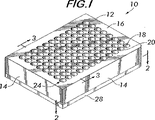
図1に本発明によるマルチウェル・プレート10を示す。プレート10は、垂下する側面部14が結合した実質的平面部材12である。プレートは、上面16および複数のウェル18を有し、各ウェルは上面16上に開口部20を有する。ウェルは、好ましくは縦横の列の規則的な配列で配置されており、実験、例えば、固相合成を含めた実験において加熱するために化合物試料を保持するようになっている。
FIG. 1 shows a
図2および3に最もよく示されるように、細長いチャンバ22は、側面部14の1つと側面部に隣接する1列または1グループのウェル24との間の平面部材12の内側で長手方向に延びる。好ましい実施形態において、チャンバは、ウェルの最も外側の列と隣接する側面部14との間の平面部材12全体の周囲に連続的に広がっている。チャンバは、常時密封され、周囲から隔離されており、蓄熱体として作用する能力を有する物質26、すなわち、マイクロ波放射によって加熱可能であり、熱を貯蔵し伝達する能力を有する物質を含むことが好ましい。好ましい物質26は、以下に記述する理由のため、液体であり、実験を行う温度よりも高い沸点を有する。
As best shown in FIGS. 2 and 3, the
図1に示すプレートは、好ましくは、ポリテトラフルオロエチレンまたはマイクロ波を透過し(すなわち、マイクロ波放射に曝したときにあまり加熱されず)、ウェル中の化合物と反応せず、少なくとも実験温度を超える高温に耐える他の比較的不活性な物質でできている。プレートは、固形ブロックから機械切削することができ、その溝は物質26で満たされ、次いで底板28で密封され、接着剤または留め具または他の適切な手段で取り付けられる。
The plate shown in FIG. 1 is preferably transparent to polytetrafluoroethylene or microwaves (ie, not very heated when exposed to microwave radiation), does not react with the compounds in the wells, and has at least the experimental temperature. Made of other relatively inert materials that can withstand higher temperatures. The plate can be machined from a solid block whose grooves are filled with
図4にマルチウェル・プレート30の別の実施形態を示す。1つまたは複数のチャンバ22が、平面部材12に開けられ、各チャンバはウェル34のそれぞれの列と側面部14の間に位置する。図5に示すように、チャンバ22は好ましくは平面部材12全体を包囲し、流体が互いに行き来する。必要に応じて1つまたは複数の栓36を用いてチャンバを密封して、流体内容物が漏洩するのを防止する。チャンバ22と連通する注入口38は、好ましくは平面部材12の上面16上に位置して、チャンバ中に液体を注入できるようになっている。図4に示すように2つの注入口38を用いて、そのうち1つは液体をもう一方に注入したときにチャンバから空気が逃げるようにすると都合がよい。
FIG. 4 shows another embodiment of the multiwell plate 30. One or
図6に示すように、プレートの側面1つにつき単一のチャンバ22を使用することができるが、本発明は、図7に示すように、プレートの1つまたは複数の側面に沿って積層して配置された複数のチャンバ22を使用することも企図している。この実施形態によって、1列のウェルとプレート側面部14の間により多くの流体を入れることができ、それによって以下に示すように蓄熱体としてのチャンバの有効性が増す。
Although a
チャンバ22は、適切な物質26で満たされると、蓄熱体として働いて側面14からマイクロ波オーブン内のより低温の周囲空気への熱損失が低下または防止される。この物質は、側面に隣接して位置するウェル24からわずかしか熱を伝達しない緩衝剤として働き、したがって、ウェルすべてが実質的に同じ温度を維持し、プレート中央のウェルと側面14により近いウェルとの有意な温度勾配を回避することが可能になる。有意な温度勾配を回避することによって、実験結果の整合性が損なわれず、本発明によるマルチウェル・プレートの全ウェル中の反応物すべてに対して意味のある結果が得られることになる。
When the
マルチウェル・プレートが確実に有効に働くためには、チャンバ22内の液体は、実験を行う温度よりも高い沸点を有することが好ましい。これによって、チャンバは液体が充満した状態に確実に維持され、温度勾配を軽減または排除する蓄熱体として作用し続け、また、オーブン内の雰囲気を汚染し実験の整合性を損ない得る蒸気は発生しない。密封チャンバ内でその沸点に加熱された液体はかなりの圧力になり、チャンバが破裂して熱い液体および蒸気をオーブン中に吐き出す恐れがあるので、安全性も重要である。
In order to ensure that the multiwell plate works effectively, the liquid in the
例えば、約130℃の一定温度にウェル内の試料を加熱するように設計した実験の場合、チャンバ22内の好ましい液体26は、1気圧で沸点が202℃であるN−メチルピロリジノンである。液体物質26の沸点が実験温度より少なくとも50℃高いと、ほとんどの用途で妥当な安全域がもたらされる。
For example, for experiments designed to heat the sample in the well to a constant temperature of about 130 ° C., the
寸法が124×85×27mmのポリテトラフルオロエチレン製標準96ウェル・マルチウェル・プレートの場合、プレートの周囲に有効な蓄熱体を形成し、温度勾配を軽減して相対的に有意でなくするには約7mLの液体で十分であることが判明している。ただし、温度勾配をさらに効果的に少なくするためには液体の体積をより大きくすることが好ましい。 In the case of a standard 96-well multi-well plate made of polytetrafluoroethylene with dimensions of 124 x 85 x 27 mm, an effective heat storage is formed around the plate, reducing the temperature gradient and making it relatively insignificant. It has been found that about 7 mL of liquid is sufficient. However, in order to further effectively reduce the temperature gradient, it is preferable to increase the volume of the liquid.
図8に示す別の実施形態において、蓄熱体40は、平面部材12の周囲に、ウェル18
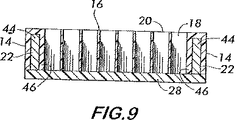
に隣接する側面46に沿って長手方向に固体材料の細長いボデー44を配置することによって形成される。細長いボデーは、側面部14を形成すると考えることができ、好ましくは平面部材全体の周囲に連続して広がる。ボデー44を含む材料は、マイクロ波によって実験温度まで容易に加熱可能であり、それによって蓄熱体として作用して隣接のウェル18からマイクロ波オーブン内のより低温の雰囲気へと熱が失われるのを防止する。平面部材10を包囲する固形ボデーが存在することによって、中央ウェルと側面46に隣接するウェルとの間にあらゆる有意な温度勾配が形成されるのが防止される。生成し得るあらゆる温度勾配が、細長いボデー44自体でとどまる可能性が高い。ボデー44は、セラミック材料および他の固体材料で形成することができる。ボデー44がゼラチン質材料である場合、図9に示すように側面46と側面部14の間のチャンバ22内に配置し、底板28を取り付けてチャンバを密封することができる。これは図3に示す実施形態に類似している。
In another embodiment shown in FIG. 8, the
Is formed by disposing an
図9にマイクロ波オーブン(図示せず)内に配置した回転台48上で使用する本発明によるマルチウェル・プレート10を示す。プレート10は、回転台48上の好ましくはプレートを確実に適切に配置するくぼみ52内に置かれたトレイ50中に置かれていることが好ましい。回転アーム54によって、温度計などの測定装置が運ばれてプレート上に載せられ、ウェル中の化合物試料の温度をモニターすることが可能になる。回転台には動力が供給され、オーブン内で垂直軸56の回りを回転してすべてのプレート中のすべてのウェルがマイクロ波によって確実に均一に加熱されるようになっている。
FIG. 9 shows a
得られた実験結果から、化学合成試験においてマイクロ波オーブン中で使用するときに、本発明によるマルチウェル・プレートが有効であることが証明されている。このようなプレートではウェルすべての反応物の90%から100%が生成物に転化する。これは、周辺部に隣接するウェル中の反応物のわずか10%から20%しか生成物に転化しない従来技術によるマルチウェル・プレートとは対照的である。 The obtained experimental results prove that the multiwell plate according to the present invention is effective when used in a microwave oven in chemical synthesis tests. In such a plate, 90% to 100% of the reaction in all wells is converted to product. This is in contrast to prior art multi-well plates where only 10% to 20% of the reactants in the wells adjacent to the periphery are converted to product.
Claims (16)
垂下する側面部が結合し、上面を有する実質的平面部材と、
前記平面部材内に位置し、前記化合物の試料を保持するようになされた複数のウェルであって、前記ウェルの各々が前記上面上に位置する開口部を有する複数のウェルと、
前記複数のウェルの最も外側の列と、それと隣接する前記側面部との間の平面部材全体の周囲に連続して広がっている細長いチャンバであって、蓄熱体として作用する能力を有し、かつ、他のウェル中にある試料に対する最も外側の列のウェル中にある前記試料の温度変化に抵抗する流体を含むようになっている、細長いチャンバとを備え、他の部分には細長いチャンバを備えない上記のプレート。 A multi-well plate for holding test compounds used in a microwave oven ,
A substantially planar member having a top surface coupled with a pendant side surface;
Wherein positioned in a plane member, a plurality of wells in which the sample was made to retain the compound, and a plurality of wells have the opening each of said wells is located on the upper surface,
An elongate chamber continuously extending around the entire planar member between the outermost row of the plurality of wells and the side portion adjacent thereto , and having the ability to act as a heat storage; and , which is to include a fluid that resists the outermost temperature change of the sample in the wells of columns for the sample that is in another window e le, e Bei a fine long chamber, the other part The above plate without an elongated chamber .
垂下する複数の側面部が結合し、上面を有する実質的平面部材と、
前記平面部材内に位置し、前記化合物の試料を保持するようになされた複数のウェルであって、前記ウェルの各々が前記上面上に位置する開口部を有する複数のウェルと、
前記複数のウェルの最も外側の列と、それと隣接する前記側面部との間の平面部材全体の周囲に連続して広がっている細長いチャンバと、
前記細長いチャンバに含まれ、他のウェル中にある試料に対する最も外側の列のウェル中にある前記試料の温度変化に抵抗する蓄熱体として作用する能力を有する流体とを備え、他の部分には細長いチャンバを備えない上記のプレート。 A multi-well plate for holding test compounds used in a microwave oven ,
A substantially planar member having a plurality of hanging side surfaces coupled and having an upper surface;
Wherein positioned in a plane member, a plurality of wells in which the sample was made to retain the compound, and a plurality of wells have the opening each of said wells is located on the upper surface,
An elongate chamber extending continuously around the entire planar member between the outermost row of the plurality of wells and the side portion adjacent thereto ;
Wherein contained within the elongated chamber, e Bei a fluid which has the ability to act as a heat storage body to resist the outermost temperature change of the sample in the wells of columns for the sample that is in another window E le, other A plate as described above, wherein the part does not have an elongated chamber .
上面を有し、平面部材に結合した複数の側面部を有する実質的平面部材と、
前記平面部材内に位置し、前記化合物の試料を保持するようになされた複数のウェルであって、前記ウェルの各々が前記上面上に位置する開口部を有する複数のウェルと、
平面部材の周囲に実質的に連続して広がる細長いボデーであって、他のウェル中にある試料に対する最も外側のウェル中にある前記試料の温度変化に抵抗する蓄熱体として作用する能力を有する前記細長いボデーとを備え、他の部分には細長いボデーを備えない上記のプレート。 A multi-well plate for holding test compounds used in a microwave oven ,
Has a top surface, a substantially planar member having a plurality of side portions coupled to the flat surface members,
Wherein positioned in a plane member, a plurality of wells in which the sample was made to retain the compound, and a plurality of wells have the opening each of said wells is located on the upper surface,
An elongated body extending substantially continuously around the planar member, the ability to act as a heat storage body to resist the temperature change of the sample in the most in the outer wells to the sample which is in the other U E le Said plate having said elongated body and having no elongated body in the other part .
Applications Claiming Priority (2)
| Application Number | Priority Date | Filing Date | Title |
|---|---|---|---|
| US09/875,999 US6676905B2 (en) | 2001-06-07 | 2001-06-07 | Multi-well plate with perimeteral heat reservoir |
| PCT/US2002/015275 WO2002100545A1 (en) | 2001-06-07 | 2002-05-13 | Multi-well plate with perimeteral heat reservoir |
Publications (3)
| Publication Number | Publication Date |
|---|---|
| JP2004537397A JP2004537397A (en) | 2004-12-16 |
| JP2004537397A5 JP2004537397A5 (en) | 2005-12-22 |
| JP4291689B2 true JP4291689B2 (en) | 2009-07-08 |
Family
ID=25366747
Family Applications (1)
| Application Number | Title | Priority Date | Filing Date |
|---|---|---|---|
| JP2003503357A Expired - Fee Related JP4291689B2 (en) | 2001-06-07 | 2002-05-13 | Multiwell plate with heat storage around |
Country Status (19)
| Country | Link |
|---|---|
| US (1) | US6676905B2 (en) |
| EP (1) | EP1399263B1 (en) |
| JP (1) | JP4291689B2 (en) |
| KR (1) | KR20040012902A (en) |
| CN (1) | CN1227067C (en) |
| AR (1) | AR034082A1 (en) |
| AT (1) | ATE439910T1 (en) |
| BR (1) | BR0210279A (en) |
| CA (1) | CA2449526A1 (en) |
| CO (1) | CO5380011A1 (en) |
| DE (1) | DE60233403D1 (en) |
| HK (1) | HK1068111A1 (en) |
| IL (1) | IL159147A0 (en) |
| MX (1) | MXPA03011116A (en) |
| NO (1) | NO20035432D0 (en) |
| NZ (1) | NZ529784A (en) |
| TW (1) | TWI225428B (en) |
| WO (1) | WO2002100545A1 (en) |
| ZA (1) | ZA200309217B (en) |
Families Citing this family (31)
| Publication number | Priority date | Publication date | Assignee | Title |
|---|---|---|---|---|
| US6660233B1 (en) * | 1996-01-16 | 2003-12-09 | Beckman Coulter, Inc. | Analytical biochemistry system with robotically carried bioarray |
| DE10028323A1 (en) * | 2000-06-07 | 2001-12-20 | Evotec Biosystems Ag | Microtiter plate or chip for containing biological or chemical samples, comprises a flat plastic sheet containing wells, a supporting core made from high melting point material surrounding each well being embedded in plastic sheet |
| US6884396B2 (en) * | 2001-03-22 | 2005-04-26 | Thomas W. Astle | Pipettor reservoir for particulate-containing liquids |
| US20040043494A1 (en) * | 2002-08-30 | 2004-03-04 | Amorese Douglas A. | Apparatus for studying arrays |
| JP3727026B2 (en) * | 2003-04-10 | 2005-12-14 | 博行 野地 | Micro chamber used for detecting single-molecule enzyme activity and method for preparing droplets of 1000 fL or less |
| US20050112033A1 (en) * | 2003-09-08 | 2005-05-26 | Irm, Llc | Multi-well containers, systems, and methods of using the same |
| US20050280811A1 (en) * | 2003-09-19 | 2005-12-22 | Donald Sandell | Grooved high density plate |
| US20050225751A1 (en) * | 2003-09-19 | 2005-10-13 | Donald Sandell | Two-piece high density plate |
| US20050069462A1 (en) * | 2003-09-30 | 2005-03-31 | International Business Machines Corporation | Microfluidics Packaging |
| US20050069949A1 (en) * | 2003-09-30 | 2005-03-31 | International Business Machines Corporation | Microfabricated Fluidic Structures |
| EP1609850A1 (en) * | 2004-06-24 | 2005-12-28 | Biovir v/Jacob Mollenbach | Culture dish for culturing biological cells |
| US20060096885A1 (en) * | 2004-11-11 | 2006-05-11 | Zhiyin Shan | Specimen storage apparatus |
| US20070172395A1 (en) * | 2006-01-20 | 2007-07-26 | Applera Corporation | Thermally Conductive Microplate |
| FR2901360A1 (en) * | 2006-05-16 | 2007-11-23 | Horiba Abx Sas Soc Par Actions | PACKAGING DEVICE FOR BIOLOGICAL ANALYSIS |
| WO2008063135A1 (en) | 2006-11-24 | 2008-05-29 | Agency For Science, Technology And Research | Apparatus for processing a sample in a liquid droplet and method of using the same |
| US9874501B2 (en) | 2006-11-24 | 2018-01-23 | Curiox Biosystems Pte Ltd. | Use of chemically patterned substrate for liquid handling, chemical and biological reactions |
| JP5590599B2 (en) * | 2007-03-13 | 2014-09-17 | ザ・プロウボウスト・フェロウズ・ファウンデーション・スカラーズ・アンド・ザ・アザー・メンバーズ・オブ・ボード・オブ・ザ・カレッジ・オブ・ザ・ホリー・アンド・アンデバイデッド・トリニティ・オブ・クイーン・エリザベス・ニア・ダブリン | Multiwell plate |
| US20080245787A1 (en) * | 2007-04-03 | 2008-10-09 | Joseph Lambert | Controlling and moderating microwave energy in concurrent multiple sample well applications |
| KR100867180B1 (en) * | 2007-05-10 | 2008-11-06 | 정영조 | Sliding assembly for mobile-phone |
| WO2013114217A1 (en) | 2012-02-05 | 2013-08-08 | Curiox Biosystems Pte Ltd. | Array plates and methods for making and using same |
| US10725020B2 (en) | 2007-11-14 | 2020-07-28 | Curiox Biosystems Pte Ltd. | High throughput miniaturized assay system and methods |
| KR100970983B1 (en) * | 2008-10-02 | 2010-07-20 | 주식회사 한빛티앤아이 | Spring module for sliding apparatus |
| WO2012011877A2 (en) | 2010-07-23 | 2012-01-26 | Curiox Biosystems Pte Ltd | Apparatus and method for multiple reactions in small volumes |
| KR101137250B1 (en) | 2011-12-22 | 2012-04-20 | 주식회사 아스타 | Apparatus and method for processing sample using microwave |
| US9557318B2 (en) | 2013-07-09 | 2017-01-31 | Curiox Biosystems Pte Ltd. | Array plates for washing samples |
| US10545139B2 (en) | 2015-06-16 | 2020-01-28 | Curiox Biosystems Pte Ltd. | Methods and devices for performing biological assays using magnetic components |
| CN105547803B (en) * | 2016-01-21 | 2018-04-17 | 核工业理化工程研究院 | Micro-wave diminishing pot rack |
| USD867614S1 (en) * | 2016-07-23 | 2019-11-19 | Meso Scale Technologies, Llc. | Plate lids |
| EP3607580B1 (en) | 2017-04-05 | 2023-05-31 | Curiox Biosystems Pte Ltd. | Methods, devices, and apparatus for washing samples on array plates |
| JP2019154434A (en) * | 2018-03-07 | 2019-09-19 | 国立大学法人鳥取大学 | Cell culture dish |
| CN112934290B (en) * | 2021-05-14 | 2021-10-12 | 山东科技职业学院 | Experimental equipment matched with digestion tube |
Family Cites Families (24)
| Publication number | Priority date | Publication date | Assignee | Title |
|---|---|---|---|---|
| US3273968A (en) * | 1960-03-23 | 1966-09-20 | Theodor H Benzinger | Heat-burst microcalorimeter |
| US3211531A (en) * | 1963-01-21 | 1965-10-12 | Theodor H Benzinger | Miniaturized reaction vessel |
| US3245758A (en) * | 1963-09-30 | 1966-04-12 | Theodor H Benzinger | Calorimetry for photochemical reactions |
| US4657867A (en) * | 1984-11-01 | 1987-04-14 | Becton, Dickinson And Company | Multiwell tissue culture assembly with features for reduced media evaporation |
| US4786601A (en) * | 1985-03-15 | 1988-11-22 | Rothenberg Barry E | Tissue culture holder |
| US4673651A (en) * | 1985-03-15 | 1987-06-16 | Rothenberg Barry E | Multi-cell tray |
| DD239473A1 (en) | 1985-07-01 | 1986-09-24 | Zeiss Jena Veb Carl | SAMPLE SUPPLIER FOR DISCRETE ANALYSIS OF LIQUID ANALYSIS ASSAYS |
| US5255976A (en) * | 1992-07-10 | 1993-10-26 | Vertex Pharmaceuticals Incorporated | Temperature gradient calorimeter |
| US5932075A (en) * | 1993-10-28 | 1999-08-03 | Commonwealth Scientific And Industrial Research Organisation | Batch microwave reactor |
| EP0728038B1 (en) * | 1993-11-11 | 1998-07-08 | LAUTENSCHLÄGER, Werner | Device for initiating and/or furthering chemical or physical processes in a material, especially sample material |
| US5451524A (en) | 1994-02-01 | 1995-09-19 | The Gillette Company | In vitro chamber for human organ tissue samples |
| US5609826A (en) * | 1995-04-17 | 1997-03-11 | Ontogen Corporation | Methods and apparatus for the generation of chemical libraries |
| US5716584A (en) * | 1995-09-07 | 1998-02-10 | Pathogenesis Corporation | Device for the synthesis of compounds in an array |
| US5746982A (en) | 1996-02-29 | 1998-05-05 | Advanced Chemtech, Inc. | Apparatus for automated synthesis of chemical compounds |
| FR2751830B1 (en) * | 1996-07-23 | 1998-10-23 | Prolabo Sa | DEVICE FOR CARRYING OUT MICROWAVE CHEMICAL REACTIONS ON A LARGE QUANTITY OF PRODUCTS |
| US5866342A (en) | 1996-09-27 | 1999-02-02 | Glaxo Group Limited | Systems and methods for the synthesis of organic compounds |
| US6126904A (en) | 1997-03-07 | 2000-10-03 | Argonaut Technologies, Inc. | Apparatus and methods for the preparation of chemical compounds |
| WO1999054031A1 (en) | 1998-04-23 | 1999-10-28 | Otter Coast Automation, Inc. | Method and apparatus for synthesis of libraries of organic compounds |
| US6086831A (en) | 1998-06-10 | 2000-07-11 | Mettler-Toledo Bohdan, Inc. | Modular reaction block assembly with thermoelectric cooling and heating |
| US6306658B1 (en) | 1998-08-13 | 2001-10-23 | Symyx Technologies | Parallel reactor with internal sensing |
| US6238627B1 (en) * | 1998-08-26 | 2001-05-29 | Arqule, Inc. | Reaction block and cover |
| US6193064B1 (en) | 1998-11-04 | 2001-02-27 | J. G. Finneran Associates, Inc. | Multi-tier vial plate |
| DE19904716A1 (en) * | 1999-02-05 | 2000-08-31 | Bilatec Ges Zur Entwicklung Bi | Device for the selective tempering of individual containers |
| AU2002226050A1 (en) * | 2000-12-12 | 2002-06-24 | 3-Dimensional Pharmaceuticals, Inc. | Microtiter plate with integral heater |
-
2001
- 2001-06-07 US US09/875,999 patent/US6676905B2/en not_active Expired - Fee Related
-
2002
- 2002-05-13 IL IL15914702A patent/IL159147A0/en unknown
- 2002-05-13 DE DE60233403T patent/DE60233403D1/en not_active Expired - Lifetime
- 2002-05-13 NZ NZ529784A patent/NZ529784A/en unknown
- 2002-05-13 AT AT02778926T patent/ATE439910T1/en active
- 2002-05-13 JP JP2003503357A patent/JP4291689B2/en not_active Expired - Fee Related
- 2002-05-13 MX MXPA03011116A patent/MXPA03011116A/en active IP Right Grant
- 2002-05-13 CN CNB028113535A patent/CN1227067C/en not_active Expired - Fee Related
- 2002-05-13 EP EP02778926A patent/EP1399263B1/en not_active Expired - Lifetime
- 2002-05-13 BR BR0210279-0A patent/BR0210279A/en not_active Application Discontinuation
- 2002-05-13 CA CA002449526A patent/CA2449526A1/en not_active Abandoned
- 2002-05-13 KR KR10-2003-7015995A patent/KR20040012902A/en not_active Application Discontinuation
- 2002-05-13 WO PCT/US2002/015275 patent/WO2002100545A1/en active IP Right Grant
- 2002-05-24 TW TW091111073A patent/TWI225428B/en not_active IP Right Cessation
- 2002-05-31 CO CO02046941A patent/CO5380011A1/en not_active Application Discontinuation
- 2002-06-04 AR ARP020102070A patent/AR034082A1/en unknown
-
2003
- 2003-11-26 ZA ZA200309217A patent/ZA200309217B/en unknown
- 2003-12-05 NO NO20035432A patent/NO20035432D0/en not_active Application Discontinuation
-
2005
- 2005-01-10 HK HK05100185A patent/HK1068111A1/en not_active IP Right Cessation
Also Published As
| Publication number | Publication date |
|---|---|
| CN1512916A (en) | 2004-07-14 |
| NO20035432D0 (en) | 2003-12-05 |
| US6676905B2 (en) | 2004-01-13 |
| CA2449526A1 (en) | 2002-12-19 |
| IL159147A0 (en) | 2004-06-01 |
| EP1399263B1 (en) | 2009-08-19 |
| EP1399263A4 (en) | 2006-11-02 |
| BR0210279A (en) | 2004-07-20 |
| KR20040012902A (en) | 2004-02-11 |
| JP2004537397A (en) | 2004-12-16 |
| NZ529784A (en) | 2005-09-30 |
| CO5380011A1 (en) | 2004-03-31 |
| MXPA03011116A (en) | 2004-03-19 |
| DE60233403D1 (en) | 2009-10-01 |
| CN1227067C (en) | 2005-11-16 |
| WO2002100545A8 (en) | 2004-03-04 |
| TWI225428B (en) | 2004-12-21 |
| AR034082A1 (en) | 2004-01-21 |
| US20020187078A1 (en) | 2002-12-12 |
| ZA200309217B (en) | 2004-09-15 |
| HK1068111A1 (en) | 2005-04-22 |
| EP1399263A1 (en) | 2004-03-24 |
| ATE439910T1 (en) | 2009-09-15 |
| WO2002100545A1 (en) | 2002-12-19 |
Similar Documents
| Publication | Publication Date | Title |
|---|---|---|
| JP4291689B2 (en) | Multiwell plate with heat storage around | |
| JP2004537397A5 (en) | ||
| EP2402460B1 (en) | Method and apparatus for generating thermal melting curves in a microfluidic device | |
| US6893613B2 (en) | Parallel chemistry reactor with interchangeable vessel carrying inserts | |
| US6402369B1 (en) | Arrayable thermal assays | |
| US20160160265A1 (en) | Devices and methods for thermally-mediated chemical reactions | |
| US20020001538A1 (en) | Multi-temperature modular reactor and method of using same | |
| CA2716337A1 (en) | Thermocycler and sample vessel for rapid amplification of dna | |
| CA2430217A1 (en) | Method for preventing chemical crosstalk in enzyme-linked reactions, and associated arrangement | |
| JP2013007688A (en) | Cool reagent storage and nucleic acid analyzer | |
| WO2000026096A9 (en) | Multi-tier vial plate | |
| ATE401126T1 (en) | HEATING OF MULTI-CHAMBER CONTAINERS | |
| JP2018533913A (en) | Systems and methods for biological analysis | |
| EP1921898A1 (en) | Method and device for heating multiple samples by microwave radiation | |
| AU2002348487B2 (en) | Multi-well plate with perimeteral heat reservoir | |
| US10884006B2 (en) | Instrument and method for automatically heat-sealing a microplate | |
| US20050036536A1 (en) | High throughout energy array | |
| AU2002348487A1 (en) | Multi-well plate with perimeteral heat reservoir | |
| US7122159B2 (en) | High pressure parallel reactor with individually sealable vessels | |
| WO2009040743A2 (en) | Micro-fluidic reactor system including reaction chambers and method for filling and emptying the reaction chambers | |
| AU722800B2 (en) | Composite body and method of use | |
| SU1303922A1 (en) | Method of determining kinetic parameters of reaction in volume of loose material | |
| ITMI981683A1 (en) | THERMAL CYCLIZER FOR BIOTECHNOLOGICAL REACTIONS IN PARTICULAR FOR POYLMERASE CHAIN REACTION AND RELATED CONTAINER FOR REACTIONS |
Legal Events
| Date | Code | Title | Description |
|---|---|---|---|
| A521 | Request for written amendment filed |
Free format text: JAPANESE INTERMEDIATE CODE: A523 Effective date: 20050316 |
|
| A621 | Written request for application examination |
Free format text: JAPANESE INTERMEDIATE CODE: A621 Effective date: 20050316 |
|
| A977 | Report on retrieval |
Free format text: JAPANESE INTERMEDIATE CODE: A971007 Effective date: 20071024 |
|
| A131 | Notification of reasons for refusal |
Free format text: JAPANESE INTERMEDIATE CODE: A131 Effective date: 20071030 |
|
| A521 | Request for written amendment filed |
Free format text: JAPANESE INTERMEDIATE CODE: A523 Effective date: 20080117 |
|
| TRDD | Decision of grant or rejection written | ||
| A01 | Written decision to grant a patent or to grant a registration (utility model) |
Free format text: JAPANESE INTERMEDIATE CODE: A01 Effective date: 20090331 |
|
| A01 | Written decision to grant a patent or to grant a registration (utility model) |
Free format text: JAPANESE INTERMEDIATE CODE: A01 |
|
| A61 | First payment of annual fees (during grant procedure) |
Free format text: JAPANESE INTERMEDIATE CODE: A61 Effective date: 20090403 |
|
| R150 | Certificate of patent or registration of utility model |
Free format text: JAPANESE INTERMEDIATE CODE: R150 |
|
| FPAY | Renewal fee payment (event date is renewal date of database) |
Free format text: PAYMENT UNTIL: 20120410 Year of fee payment: 3 |
|
| LAPS | Cancellation because of no payment of annual fees |