JP4288552B2 - Continuous rolling method and equipment - Google Patents
Continuous rolling method and equipment Download PDFInfo
- Publication number
- JP4288552B2 JP4288552B2 JP2001200754A JP2001200754A JP4288552B2 JP 4288552 B2 JP4288552 B2 JP 4288552B2 JP 2001200754 A JP2001200754 A JP 2001200754A JP 2001200754 A JP2001200754 A JP 2001200754A JP 4288552 B2 JP4288552 B2 JP 4288552B2
- Authority
- JP
- Japan
- Prior art keywords
- continuous
- welding
- welding machine
- machine
- flash
- Prior art date
- Legal status (The legal status is an assumption and is not a legal conclusion. Google has not performed a legal analysis and makes no representation as to the accuracy of the status listed.)
- Expired - Lifetime
Links
- 238000005096 rolling process Methods 0.000 title claims description 157
- 238000000034 method Methods 0.000 title claims description 105
- 238000003466 welding Methods 0.000 claims description 277
- 239000000463 material Substances 0.000 claims description 153
- 238000010438 heat treatment Methods 0.000 claims description 91
- 238000005520 cutting process Methods 0.000 claims description 57
- 230000008569 process Effects 0.000 claims description 20
- 239000000109 continuous material Substances 0.000 claims description 14
- 238000009749 continuous casting Methods 0.000 claims description 12
- 238000011144 upstream manufacturing Methods 0.000 claims description 10
- 238000009499 grossing Methods 0.000 claims description 9
- 238000005304 joining Methods 0.000 claims description 9
- 230000003028 elevating effect Effects 0.000 claims description 5
- 238000003825 pressing Methods 0.000 claims description 5
- 230000001360 synchronised effect Effects 0.000 claims description 5
- 238000011010 flushing procedure Methods 0.000 claims description 2
- 238000010586 diagram Methods 0.000 description 12
- 229910000831 Steel Inorganic materials 0.000 description 7
- 239000010959 steel Substances 0.000 description 7
- 230000000694 effects Effects 0.000 description 5
- 230000008901 benefit Effects 0.000 description 4
- 238000004519 manufacturing process Methods 0.000 description 3
- 238000004904 shortening Methods 0.000 description 3
- 238000005266 casting Methods 0.000 description 2
- 238000007796 conventional method Methods 0.000 description 2
- 230000001186 cumulative effect Effects 0.000 description 2
- 230000006872 improvement Effects 0.000 description 2
- 230000004044 response Effects 0.000 description 2
- 238000007493 shaping process Methods 0.000 description 2
- 239000002699 waste material Substances 0.000 description 2
- 238000010304 firing Methods 0.000 description 1
- 238000009434 installation Methods 0.000 description 1
- 238000005259 measurement Methods 0.000 description 1
- 230000007246 mechanism Effects 0.000 description 1
- 238000002844 melting Methods 0.000 description 1
- 230000008018 melting Effects 0.000 description 1
- 238000011084 recovery Methods 0.000 description 1
- 238000007634 remodeling Methods 0.000 description 1
- 230000004043 responsiveness Effects 0.000 description 1
- 239000002436 steel type Substances 0.000 description 1
- 239000013077 target material Substances 0.000 description 1
Images


Landscapes
- Metal Rolling (AREA)
Description
【0001】
【発明の属する技術分野】
本発明は、フラッシュ溶接で連続化した材料から棒材、条鋼等の鉄鋼製品を製造するための連続圧延方法およびその設備に関する。
【0002】
【従来の技術】
連続鋳造によるビレットまたはブルームを材料とする連続圧延方法は従来より多くの提案があり、その方法の基本的概念は、圧延に先立ってビレット等の材料を順次溶接にて接続していき、ついで溶接部のバリを除去し、この連続したエンドレス状の材料を圧延ラインに供給して各種の鉄鋼製品を圧延するものである。
ビレット等の溶接には一般にフラッシュ溶接が用いられる。そのため、溶接部には鋳バリが生じるので、圧延前にこの鋳バリをバイトや砥石等で削除するのが通例である。
【0003】
このような連続圧延方法は、例えばEP0832700A1号公報に開示されている。しかし、この方法では溶接すべきビレットの端部を溶接前に切断することとしている。これは、溶接すべき2つのビレット端面が平面でかつ平行になっていないと完全な接合が得られないという意図からくるものである。そのため、平行な2枚の回転刃を有するクロップ切断機をフラッシュ溶接機に設置している。
【0004】
しかしながら、ビレット端部を溶接前に切断するときは、その切断時間が溶接のタイムサイクルに影響を及ぼすことになる。また、材料の無駄が生じ、コスト面でも不利は免れない。
【0005】
【発明が解決しようとする課題】
連続圧延方法の本来の長所を活かすためには、溶接強度は圧延時の引張強度に十分に耐えることができ、なおかつ短時間で実施可能な溶接方法の確立が急務の課題である。さらに、溶接方法はできるだけシンプルでコストの上昇を抑えられる方法が望まれる。
【0006】
また、前記公報では、バリ取り機を溶接機上に設置している。つまり、バリ取り機が溶接機と一体となっているため、溶接が終了した当該溶接部に対するバリ取りが完了するまでは、溶接機は元のスタート位置に戻ることができないことになる。そのため、タイムサイクルが大幅に長くなるという課題がある。
【0007】
また、連続圧延設備は一般的に長大で大規模な設備を必要とする。したがって、設備投資が莫大なものとなるので、できるだけ既存の設備を利用できる工夫が望まれる。
【0008】
本発明は、上記のような課題を解決するためになされたものであり、ビレット等の材料の端部を溶接前に切断することなく、十分な接合強度を持つフラッシュ溶接を可能にした連続圧延方法およびその設備を提供することを目的とする。
本発明の他の目的は、溶接部のバリ取りを溶接機に依存させずに独立にバリ取りを行うことによって、タイムサイクルの短縮を可能にした連続圧延方法およびその設備を提供することにある。
本発明のさらに他の目的は、既存の設備を利用できるように小規模で連続圧延を実施可能にすることにある。
【0009】
【課題を解決するための手段】
本発明の請求項1に記載の連続圧延方法は、連続鋳造機から直送される材料を該連続鋳造機から第1圧延スタンドの間で順次先行材の後端と後行材の先端を走間にてフラッシュ溶接する工程と、その後溶接部のバリを除去する工程を含み、連続した材料となして圧延する連続圧延方法において、フラッシュ溶接工程は、連続フラッシュ加熱式溶接法により材料の端部を溶接前に切断することなく、溶接機のプラテンを電気油圧式シリンダ装置により5Hz以上の周波数で押し、引きすることによって、溶接初期(開始時)から連続的にフラッシュを発生させることにより該材料の端部を加熱し平滑化する第1段階と、該第1段階に続いて後行材を先行材にアプセットして接合する第2段階とを含み、溶接部のバリ取り工程は、溶接機の外部下流側に固定したバリ取り機により行うことを特徴とする。
【0010】
本発明による材料のフラッシュ溶接は、材料の端部において連続的にフラッシュを発生させることにより該材料の端部を加熱し平滑化する第1段階と、該第1段階に続いて後行材を先行材にアプセットして接合する第2段階とを含む「連続フラッシュ加熱式溶接」である。また、溶接機のプラテンの押し、引きの周波数を5Hz以上とすることにより、前記連続フラッシュ加熱式溶接の実施が可能となる。このような高応答性をもつシステムとしては電気油圧制御システムが好適である。したがって、材料端部の自己整形・平滑化効果があるため、材料の端部を溶接前に切断しなくても、十分な強度でもって溶接することができる。また、溶接部のバリ取り工程を溶接機の外部下流側に固定したバリ取り機によって行うことにより、バリ取り工程を溶接工程と別個独立に行うことができるため、バリ取り時間が溶接時間に影響することが全くなく、したがって、サイクルタイムは溶接時間で決まることになるため、更なるサイクルタイムの短縮が可能となる。
よって、本発明は、連続圧延方法本来の高能率生産、省エネルギー化の向上に貢献するものとなる。
【0011】
本発明の請求項2に記載の連続圧延方法は、加熱炉から抽出される材料を該加熱炉から第1圧延スタンドの間で順次先行材の後端と後行材の先端を走間にてフラッシュ溶接する工程と、その後溶接部のバリを除去する工程を含み、連続した材料となして圧延する連続圧延方法において、フラッシュ溶接工程は、連続フラッシュ加熱式溶接法により材料の端部を溶接前に切断することなく、溶接機のプラテンを電気油圧式シリンダ装置により5Hz以上の周波数で押し、引きすることによって、溶接初期(開始時)から連続的にフラッシュを発生させることにより該材料の端部を加熱し平滑化する第1段階と、該第1段階に続いて後行材を先行材にアプセットして接合する第2段階とを含み、溶接部のバリ取り工程は、溶接機の外部下流側に固定したバリ取り機により行うことを特徴とする。
【0012】
請求項2の発明は、請求項1の発明が連続鋳造によるビレットまたはブルームを材料とするのに対し、加熱炉から抽出されるビレットまたはブルームを材料とするものであり、製造設備の規模に配慮したものである。発明の効果は請求項1と同様である。
【0013】
本発明の請求項3に記載の連続圧延方法は、圧延機と圧延機の間で順次先行材の後端と後行材の先端を走間にてフラッシュ溶接する工程と、その後溶接部のバリを除去する工程を含み、連続した材料となして圧延する連続圧延方法において、被圧延材の先端部および後端部を切断する工程を含み、フラッシュ溶接工程は、溶接機のプラテンを電気油圧式シリンダ装置により5Hz以上の周波数で押し、引きすることによって、連続フラッシュ加熱式溶接法により溶接初期(開始時)から連続的にフラッシュを発生させることにより被圧延材の端部を加熱し平滑化する第1段階と、該第1段階に続いて後行材を先行材にアプセットして接合する第2段階とを含み、溶接部のバリ取り工程は、溶接機の外部下流側に定着したバリ取り機により行うことを特徴とする。
【0014】
請求項3の発明は、圧延機と圧延機の間で本発明の連続圧延方法を実施するものである。ただし、この場合には、材料は一般的に粗圧延された被圧延材料であり、そのため先後端部はクロップ部となっていることから、先後端部を溶接前に切断する工程が必要となる。クロップ部切断後の被圧延材に対して、前記連続フラッシュ加熱式溶接を行い、その後外部固定式のバリ取り機により溶接部のバリ取りを行うことになる。
【0015】
本発明の請求項4に記載の連続圧延方法は、請求項1から請求項3のいずれかに記載の連続圧延方法において、フラッシュ時の溶接電流あるいは電力を検出し、該溶接電流あるいは電力に基づいて溶接機のプラテンの押し、引きをフィードバック制御することを特徴とする。
【0016】
請求項4の発明は、前記連続フラッシュ加熱式溶接を実施可能にするためには溶接機のプラテンの押し、引きの制御方法が問題となるので、フラッシュ時の溶接電流あるいは電力を検出することによりこの溶接電流あるいは電力に基づいてフィードバック制御することとしたものである。
【0019】
本発明の請求項5に記載の連続圧延方法は、請求項4に記載の連続圧延方法において、溶接電源として、タップ切替式交流電源もしくはインバータ式直流電源または三相整流式直流電源を用いることを特徴とする。
【0020】
請求項5の発明は、前記連続フラッシュ加熱式溶接の実施を可能にするための溶接電源を規定したものであり、これらの溶接電源を使用し、交流においては低インピーダンス、直流においては低抵抗化により、高出力を実現し、これにより連続フラッシュを可能とするとともに短時間、高品質溶接を可能にしている。
【0021】
本発明の請求項6に記載の連続圧延方法は、請求項1から請求項5のいずれかに記載の連続圧延方法において、先行材と後行材の溶接時に、溶接機のそれぞれ相対する2つのジョーは一方が固定で、他方のみが材料の対角方向に移動することにより、固定側ジョーの面基準で芯出しをすることを特徴とする。
【0022】
このように構成することにより、ビレット等の材料をパスライン上で正確に芯出しすることができる。ジョーは直交する2辺をもつL型に構成される。
【0023】
本発明の請求項7に記載の連続圧延方法は、請求項1から請求項5のいずれかに記載の連続圧延方法において、先行材と後行材の溶接時に、溶接機のそれぞれ相対する2つのジョーがともに材料の対角方向に移動することにより芯出しをすることを特徴とする。
【0024】
相対する2つのジョーはともに材料の対角方向に移動可能にすることもでき、この場合、材料のサイズ変更に対して容易に調整が可能となる。
【0025】
本発明の請求項8に記載の連続圧延方法は、請求項1から請求項7のいずれかに記載の連続圧延方法において、溶接機のジョーのクランプ力を可変とし、フラッシュ時は低く、アプセット時は高くすることを特徴とする。
【0026】
この構成により、材料のクランプ部の過冷却を抑えることができ、連続フラッシュによる加熱時間の短縮にもつながる。
【0027】
本発明の請求項9に記載の連続圧延方法は、請求項1から請求項8のいずれかに記載の連続圧延方法において、溶接機の入側に材料の先後端を検出する先後端検出器を、該溶接機の出側または下流側にメジャリングロールを設置し、該メジャリングロールにより先行材の後端位置をトラッキングし、この信号により、先行材後端の溶接機内位置決めを行い、後行材先端の位置決めは、さきの先行材後端に後行材を押しつけることにより行うことを特徴とする。
【0028】
溶接機入側の先後端検出器と、溶接機出側または下流側のメジャリングロールで、先行材の後端位置のトラッキングができるので、先行材の後端位置が溶接機内の所定位置に来たときに後行材を追従させ、前記連続フラッシュ加熱式溶接に必要な間隔で後行材の位置決めが可能となる。
【0029】
本発明の請求項10に記載の連続圧延方法は、請求項9に記載の連続圧延方法において、溶接機の出側または下流側に設けたメジャリングロールにより先行材および溶接機の相対速度差を測定することにより、溶接機の同期速度制御を行うことを特徴とする。
【0030】
また、このメジャリングロールにより先行材と溶接機の相対速度差を測定できるので、相対速度差がゼロとなるように溶接機の走行速度を制御することにより溶接機の同期速度制御を行うことができる。
【0031】
本発明の請求項11に記載の連続圧延設備は、少なくとも1つの引出装置と、デスケーラと、搬送ローラ装置と、走間溶接機と、バリ取り機とを備え、連続鋳造機から直送される材料を該連続鋳造機と第1圧延スタンドの間で順次先行材の後端と後行材の先端を走間にてフラッシュ溶接し、その後溶接部のバリを除去し、連続した材料となして圧延する連続圧延設備において、前記走間溶接機は、走行台車と、該走行台車上に搭載した溶接機を備え、かつ、材料の端部を溶接前に切断することなく、連続的にフラッシュを発生させることにより該材料の端部を加熱し平滑化する第1段階と、該第1段階に続いて後行材を先行材にアプセットして接合する第2段階とを行う連続フラッシュ加熱式溶接機であり、前記連続フラッシュ加熱式溶接機の可動クランプ装置の駆動手段が、5Hz以上の周波数で押し、引き可能な電気油圧式シリンダ装置からなり、溶接部のバリを除去するバリ取り機は、前記連続フラッシュ加熱式溶接機の外部下流側に固定されていることを特徴とする。
【0032】
請求項11の発明は、請求項1の発明方法を実施するための設備である。本発明における連続フラッシュ加熱式溶接機は、後述するごとく下流側に固定側クランプ装置を、上流側に可動側クランプ装置を備えたものである。
【0033】
本発明の請求項12に記載の連続圧延設備は、少なくとも1つの引出装置と、デスケーラと、搬送ローラ装置と、走間溶接機と、バリ取り機とを備え、加熱炉から抽出される材料を該加熱炉と第1圧延スタンドの間で順次先行材の後端と後行材の先端を走間にてフラッシュ溶接し、その後溶接部のバリを除去し、連続した材料となして圧延する連続圧延設備において、前記走間溶接機は、走行台車と、該走行台車上に搭載した溶接機を備え、かつ、材料の端部を溶接前に切断することなく、連続的にフラッシュを発生させることにより該材料の端部を加熱し平滑化する第1段階と、該第1段階に続いて後行材を先行材にアプセットして接合する第2段階とを行う連続フラッシュ加熱式溶接機であり、前記連続フラッシュ加熱式溶接機の可動クランプ装置の駆動手段が、5Hz以上の周波数で押し、引き可能な電気油圧式シリンダ装置からなり、溶接部のバリを除去するバリ取り機は、前記連続フラッシュ加熱式溶接機の外部下流側に固定されていることを特徴とする。
【0034】
請求項12の発明は、請求項2の発明方法を実施するための設備であり、各装置は請求項11と同じである。
【0035】
本発明の請求項13に記載の連続圧延設備は、圧延機と圧延機の間に、少なくとも1つの引出装置と、クロップ切断装置と、搬送ローラ装置と、走間溶接機と、バリ取り機とを備え、圧延機と圧延機の間で順次先行材の後端と後行材の先端を走間にてフラッシュ溶接し、その後溶接部のバリを除去し、連続した材料となして圧延する連続圧延設備において、被圧延材の先端部および後端部を走間にて切断する走間切断機を備え、前記走間溶接機は、走行台車と、該走行台車上に搭載した溶接機を備え、かつ、連続的にフラッシュを発生させることにより被圧延材の端部を加熱し平滑化する第1段階と、該第1段階に続いて後行材を先行材にアプセットして接合する第2段階とを行う連続フラッシュ加熱式溶接機であり、前記連続フラッシュ加熱式溶接機の可動クランプ装置の駆動手段が、5Hz以上の周波数で押し、引き可能な電気油圧式シリンダ装置からなり、溶接部のバリを除去するバリ取り機は、前記連続フラッシュ加熱式溶接機の外部下流側に固定されていることを特徴とする。
【0036】
請求項13の発明は、請求項3の発明方法を実施するための設備である。被圧延材の先後端部を切断するために、連続フラッシュ加熱式溶接機の上流側にクロップ切断機を設置する。溶接機内部に切断機を設ける方式よりもこの方が制御しやすいものとなる。
【0037】
本発明の請求項14に記載の連続圧延設備は、請求項11から請求項13のいずれかに記載の連続圧延設備において、前記連続フラッシュ加熱式溶接機の走行区間において、前記搬送ローラ装置は、該溶接機に繋がれていて、該溶接機の走行に伴い走行方向前方のローラ間隔を順次縮小し、走行方向後方のローラ間隔を順次拡張する複数のカート式ローラ支持台からなることを特徴とする。
【0038】
溶接機は往復移動するものであるので、その前後に配設される搬送ローラ装置は、溶接機の走行に支障があってはならないことは当然である。請求項14の発明では、ショッピングカート式のローラ支持台とすることにより溶接機の走行と材料の搬送支持を可能にするものである。溶接機とローラ支持台並びに各ローラ支持台同士の連結はチェーンや伸縮自在のリンクにより連結される。
【0039】
本発明の請求項15に記載の連続圧延設備は、請求項11から請求項13のいずれかに記載の連続圧延設備において、前記連続フラッシュ加熱式溶接機の走行区間において、該溶接機は舟形ガイドを備え、前記搬送ローラ装置は、該溶接機の走行に伴い前記舟形ガイドと係合することにより走行方向前方のローラを順次下降させ、走行方向後方のローラを順次上昇復帰させる複数の昇降式ローラ支持台からなることを特徴とする。
【0040】
請求項15の発明では、昇降式のローラ支持台とし、ローラ支持台を押し下げながら溶接機が通過できるように溶接機に舟形ガイドを設ける。昇降式のローラ支持台は溶接機の移動範囲のみに配置することができる。つまり溶接機の移動範囲の後方には配置しなくてもよい利点がある。なお、ローラ支持台はバネやアクチュエータにより元の位置に復帰できる。
【0041】
本発明の請求項16に記載の連続圧延設備は、請求項11から請求項13のいずれかに記載の連続圧延設備において、前記連続フラッシュ加熱式溶接機の走行区間において、該溶接機は舟形ガイドを備え、前記搬送ローラ装置が、該溶接機の走行に伴い前記舟形ガイドと係合することにより走行方向前方のローラを順次傾倒させ、走行方向後方のローラを順次起立させる複数の起倒式ローラ支持台からなることを特徴とする。
【0042】
請求項16の発明では、起倒式のローラ支持台とし、溶接機には同じく舟形ガイドを設ける。この場合も、溶接機の移動範囲のみに起倒式ローラ支持台を配置することができる。
【0043】
本発明の請求項17に記載の連続圧延設備は、請求項11から請求項16のいずれかに記載の連続圧延設備において、前記連続フラッシュ加熱式溶接機は、下流側に固定クランプ装置と、上流側に可動クランプ装置を備え、各々の固定クランプ装置および可動クランプ装置は材料の対角方向に相対する2つのジョーを有し、これらのジョーのうち一方は固定で、他方は移動可能となっていることを特徴とする。
【0044】
本発明の請求項18に記載の連続圧延設備は、請求項11から請求項16のいずれかに記載の連続圧延設備において、前記連続フラッシュ加熱式溶接機は、下流側に固定クランプ装置と、上流側に可動クランプ装置を備え、各々の固定クランプ装置および可動クランプ装置は材料の対角方向に相対する2つのジョーを有し、これらのジョーはいずれも移動可能となっていることを特徴とする。
【0045】
本発明の請求項19に記載の連続圧延設備は、請求項11から請求項18のいずれかに記載の連続圧延設備において、前記連続フラッシュ加熱式溶接機の固定クランプ装置の出側にメジャリングロールを設置したことを特徴とする。
【0047】
本発明の請求項20に記載の連続圧延設備は、請求項11から請求項19のいずれかに記載の連続圧延設備において、溶接電流あるいは電力を検出し、該溶接電流あるいは電力に基づいて前記電気油圧式シリンダ装置をフィードバック制御する制御手段を備えたことを特徴とする。
【0048】
本発明の請求項21に記載の連続圧延設備は、請求項11から請求項20のいずれかに記載の連続圧延設備において、前記バリ取り機の内部または出側にメジャリングロールを設置したことを特徴とする。
【0049】
本発明の請求項22に記載の連続圧延設備は、請求項11から請求項21のいずれかに記載の連続圧延設備において、材料の緊急切断機を備えたことを特徴とする。
【0050】
本発明の請求項23に記載の連続圧延設備は、請求項11から請求項22のいずれかに記載の連続圧延設備において、連続化した材料を加熱する加熱装置を設けたことを特徴とする。
【0051】
【発明の実施の形態】
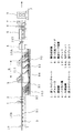
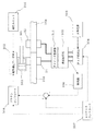
以下、本発明のいくつかの実施の形態を図面を用いて説明するが、本発明は図示の例に限定されるものでないことはいうまでもない。図1は本発明の連続圧延設備の一例を示す配置図である。
この連続圧延設備は、上流側(矢印方向が下流側である。)より、第1のピンチロール1、デスケーラ2、溶接機3、バリ取り機4、加熱装置5、第2のピンチロール6、緊急切断機7、第1圧延スタンド8をこの順に配置し、各設備間に材料を搬送するための搬送ローラ装置9を配設したものである。材料のビレット10は、上流側の連続鋳造機(図示せず)により連続鋳造され、この連続圧延設備に供給される。また、本来の圧延設備は第1圧延スタンド8より下流側に配置されており、一般に粗圧延機列、中間圧延機列、仕上圧延機列からなる。ここでの第1圧延スタンド8は、粗圧延機列の第1スタンドを示している。ビレット搬送用の搬送ローラ装置9は、固定式の搬送ローラ91と、可動式の搬送ローラ92とからなっている。この可動式の搬送ローラ92は後で詳しく述べるように、溶接機3の前後に配置され、溶接機3の走行に伴いローラ間隔が変化するようになっている。
【0052】
ビレット10は先行ビレット10Aの後端と後行ビレット10Bの先端を溶接機3により溶接接合することにより、連続した圧延材料となって第1圧延スタンド8に供給される。デスケーラ2は、主にビレット端部のスケールを溶接に先立って除去するためのものである。また、第1のピンチロール1は、後行ビレット10Bを溶接機3に送り込むためのものであるが、上流側に図示しない加熱炉を設置する場合にはその加熱炉よりビレットを引き出す装置としても働くものである。
【0053】
本発明における溶接機3は、前述したように連続フラッシュ加熱式となっており、かつ、往復走行式となっているものである。この連続フラッシュ加熱式走間溶接機3においては、溶接工程が2つの主要な段階を含んでいる。すなわち、第1段階は、ビレット端部において連続的にフラッシュを発生させることにより該ビレット端部を加熱し平滑化する段階であり、これに続く第2段階は、後行ビレット10Bを先行ビレット10Aにアプセットして接合する段階である。これにより、ビレット端部を溶接前に切断することなく、十分な溶接強度でもって短時間に溶接することを可能にするものである。
【0054】
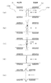
図2に、本発明の連続フラッシュ加熱式溶接方法を示す。(a)図は、先行ビレット10Aと後行ビレット10Bの端面の状態を示すものである。少し誇張して示してある。連続鋳造機から引き出されたビレットは一定の長さで熱間切断されるので、その切断面は多少なりとも凹凸面を呈している。このようなビレットが溶接機3に供給される。
溶接機3においては、固定側クランプ部のジョー31と移動側クランプ部のジョー32により、それぞれ先行ビレット10Aの後端部と後行ビレット10Bの先端部をクランプし、走間において通電状態で電気油圧シリンダ式のプラテンにより後行ビレット10Bを連続的に押し、引きする((a)図)。このときのプラテンの押し引き、つまり短絡と開放の周期を少なくとも5Hz以上が可能としている。
【0055】
この動作により、ビレット端面の最も高い凸部10a、10b同士でフラッシュが発生し、その部分が火花となって飛散し除かれる((b)図)。そして前記押し引き動作を連続的に繰り返すことにより、次の凸部10c、10dが同様に火花となって飛散し除かれ((c)図)、ビレット端面は次第に平滑な表面になってくると同時に相互の端部がアーク熱およびジュール熱によって加熱され溶融状態となってくる((d)図)。この状態になるまでの連続フラッシュによる加熱時間はビレットの断面積、鋼種、入力熱量等に応じて経験的に定められる。
【0056】
ビレット端部が溶融直前状態になるまで加熱されたとき、後行ビレット10Bをアプセットし、先行ビレット10Aと接合する((e)図)。このとき、ビレットの溶接部には周上にバリ10Cが発生するので、その後このバリ10Cは溶接機3の外部下流側に固定された定置固定式のバリ取り機4によって除去される。
【0057】
このように本発明の連続フラッシュ加熱式溶接方法は連続フラッシュによる整形・平滑化効果があるので、ビレット端面を溶接前に予め平滑にするための切断を行う必要は全くなく、したがってビレット端面に多少の凹凸部があっても何ら差し支えないものである。しかも、溶接強度はその後に実施される連続圧延時の引張強度に十分に耐え得るものである。
【0058】
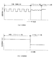
上述した本発明の連続フラッシュ加熱式溶接方法と従来のフラッシュ溶接方法を比較すると図3のようになる。(a)図が従来法であり、(b)図が本発明法である。各図は、150mm□、1000℃の普通鋼のビレットに対するもので、横軸は時間、縦軸は溶接電流(A)をあらわしている。すなわち、従来法は、溶接電圧・電流の断続的印加のため、予熱・加熱工程、フラッシュ工程、アプセット工程の3工程が必要であり、特に予熱・加熱工程では溶接電圧・電流の断続的印加を要するため15秒、フラッシュ工程で7秒、計約22秒かかっていたのに対し、本発明法では、溶接電圧・電流の連続的印加のため、加熱・フラッシュ工程とアプセット工程の2工程ですみ、約15秒でフラッシュ工程が終了するため、7秒の時間短縮が可能となる。これは、5Hz以上のプラテン押し引き性能により連続フラッシュを発生させることができるため、ビレット端部を短時間にアプセット直前の温度にまで加熱することができるからである。
したがって、本発明の連続フラッシュ加熱式溶接方法によれば、ビレットの溶接時間を大幅に短縮することができ、タイムサイクルの短縮が可能となる。しかも材料の無駄がなく歩留まりが向上する。また熱損失も少なくなるため省エネルギー化が可能となる。
【0059】
次に、本発明の連続フラッシュ加熱式溶接方法における制御方法を図4〜図6により説明する。
これらの図に示すように、この制御系は基本的に高応答性を持つ電気油圧制御系で構成する。すなわち、機械的に5Hz以上の押し引き応答特性を有する電気油圧システムからなる。油圧シリンダ300およびこれによって押し引きされるプラテン301にはそれぞれクランプジョー31、32が連結され、ビレット10Bを前記フィードバック制御で連続的に押し引きする。この電気油圧システムには、例えば、電気油圧サーボ弁302のような高応答性の比例弁あるいはDDHS(Direct Drive Hydraulic System)等が用いられる。
【0060】
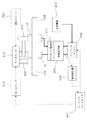
図4は高出力電源システムとして、タップ切替方式のAC電源システムの例を示し、図5はインバータ方式のDC電源システムの例を、図6は三相整流式DC電源システムの例を示すものである。
図4のタップ切替方式のAC電源システムの場合は、三相交流電源303と溶接変圧器305の間にサイリスタタップ切替器304を設け、図3(b)の加熱・フラッシュ工程の後半で二次電圧を下げるように切り替えることにより溶接品質の向上を図ることもできる。もちろん、溶接品質をそれほど重視しない場合にはタップ切替なしに高電圧のままで溶接を行えばよい。また、図4の例では、溶接変圧器305の一次電圧と電流を検出器306により検出し、その検出値とシーケンスコントローラ307からの設定値との偏差に応じてプラテンコントローラ308により電気油圧サーボ弁302を制御することによって、プラテン301をフィードバック制御している。すなわち、検出値が設定値以上のときはプラテン301を引き、設定値以下のときは押す指令を高速度処理(例えば、10ms以下で処理)して電気油圧システムに出力している。なお、前記検出値は一次電力のほかに、一次電流、二次電流、二次電力等でもよい。図中、310は油圧ユニットである。
このようなプラテン301のフィードバック制御により、5Hz以上の高応答性をもつ押し引き動作が可能となる。
【0061】
図5のインバータ方式のDC電源システムの場合は、タップ切替機能を持つインバータユニット309を設けたものである。311は二次電圧のダイオード整流部、312はサーブアンプ、313はサーボモータである。このDCシステムの場合は、一次電流を電流検出器306により検出し、検出された電流値が設定電流値となるようにシーケンスコントローラ307によりサーボアンプ312を介して油圧シリンダ300の駆動用サーボモータ313をフィードバック制御している。このDCシステムの場合は、図4のACシステムと異なり回路のインダクタンスによらず高出力が可能となる。また、タップ切替なしで一定電圧としてもよい。また、高品質を狙う場合は、インバータ入力電圧をサイリスタ式点弧角制御による可変電圧制御可能とすることにより、フラッシュプロセス中の各ステージにおいて各々最適な電圧に変えることで溶接品質の向上を図ることができる。
図6の三相整流式DC電源システムの場合も図5のDCシステムと同様の機能をもつ。
【0062】
再び図1において、この連続フラッシュ加熱式走間溶接機3は、例えば100〜150角ビレットの場合、所定のストロークSを20秒程度で前進しながらその間にビレットの溶接を完了し、10秒程度で元の位置に戻ってくる。したがって、ビレットの溶接サイクルは、30秒から40秒以下の範囲に設定できる。
【0063】
溶接機3は、ピット100内で往復移動するようになっており、ピット100内において溶接機3の前後に前記可動式搬送ローラ92が配設されている。この可動式搬送ローラ92は、例えば特開平10−216818号公報に示されたショッピングカート式のローラ支持台を使用している。このローラ支持台は、複数の装置本体をワイヤ、チェーン94等で相互に、および溶接機走行台車30とピット100間を連結したもので、溶接機3の走行に伴い走行方向前方側のローラ支持台93は走行台車30によって押され、差込式に収納されてローラ間隔を縮小し、後方側のローラ支持台93は牽引されてローラ間隔を等間隔に拡張するようになっている。
【0064】
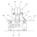
図7、図8は溶接機3の側面図と正面図である。走行輪を備えた溶接機走行台車30上には、固定側クランプ装置33と移動側クランプ装置34が設置してあり、各クランプ装置はそれぞれ油圧シリンダ35、36によってビレットをクランプするための一対のジョー31、32を備えている。固定側クランプ装置33は、先行ビレット10Aの後端部をクランプし、移動側クランプ装置34は後行ビレット10Bの先端部をクランプする。また、移動側クランプ装置34はアプセット用油圧シリンダ37を介して固定側クランプ装置33に連結され、ガイド機構38に沿って移動する。このアプセット用油圧シリンダ37に対して図4〜図6に示した電気油圧制御システムが適用される。各ビレットのクランプは電極からなるそれぞれ上下1組のジョー31、32によって行われ、図8に示すように、直角の2辺をもつL型の1組のジョー32a、32b(移動側クランプ装置のジョーを示すが、固定側クランプ装置のジョーも同様である。)がビレット10の対角方向に配設され、一方のジョー32aはクランプ装置本体に固定され、他方のジョー32bは油圧シリンダ36によりビレット10の対角方向に移動するようになっている。
【0065】
このようなジョーの形状により、固定側ジョー32a(31a)の水平面・垂直面基準で先後のビレットの調心を行うことができる。また、固定側ジョーも移動側ジョーと同様に油圧シリンダによりビレットの対角方向に移動可能にしてもよい。この場合、ビレットのサイズ変更の際にビレットサイズにかかわらず、パスラインセンタを一定とすることが可能となる。
また、各クランプ装置33、34のクランプ力は変更可能とし、連続フラッシュ時のクランプ力をアプセット時のクランプ力より低く設定することにより、ビレットのジョーによるクランプ部の過冷却を抑えることができ、またクランプ部の凹みを小さくすることができる。
【0066】
図9は走間溶接におけるビレット送り制御方法を示す説明図である。
溶接機3の入側(入側の機内または機外)にはビレット先後端を検出するビレット先後端検出器110が設けられ、また溶接機3の出側には先行ビレット10Aの後端位置をトラッキングするためのメジャリングロール111が設けられている。メジャリングロール111はパルス発振器112に接続されている。また、先行・後行ビレットの搬送速度および溶接機3の走行速度も図示しないセンサーにより検出され、かつ制御装置(図示せず)により速度制御を行っている。
【0067】
このビレット送り制御方法について説明すると下記のとおりである。まず、(a)図に示すように、溶接終了後の先行ビレット10Aの後端が、スタート点に待機している溶接機3の入側に設けられているビレット先後端検出器110上を通過すると同時に、メジャリングロール111が距離計測を開始するとともに溶接機3も走行を開始する。そして、図示しない制御装置において、先行ビレット10Aと溶接機3の速度差に基づく相対的距離の累積をメジャリングロール111のパルス発振器112のパルス数をカウントすることにより演算する。ビレット先後端検出器110と溶接機3の中心(ビレット位置決め位置)との距離Lは既知であるため、この相対的累積距離を検知することによって先行ビレット10Aの後端位置をトラッキングすることができる。そして、(b)図のように、先行ビレット10Aの後端位置が溶接機3のほぼ中心位置に来たとき、溶接機3の走行速度を先行ビレット10Aの搬送速度と同期させる。またこの時、あるいはその前から、後行ビレット10Bの搬送速度を増速し、先行ビレット10Aに追いつくように速度制御する。後行ビレット10Bの先端をビレット先後端検出器110により検出した時、その搬送速度から後行ビレット10Bの先端と先行ビレット10Aの後端との距離を演算し、両者間の間隔が所定値になったとき、あるいは後行ビレットを先行ビレットに押しつけた後に(このとき先行ビレット、溶接機、後行ビレットの三者の速度は同期している。)、先行ビレット10Aの後端部と後行ビレット10Bの先端部を前述したようにジョーでクランプし、連続フラッシュ加熱式溶接を行うものである((c)図)。なお、別に先行・後行ビレット間隔を検出する検出器を設けてもよい。
【0068】
また、後述するバリ取り機にも同様のメジャリングロールが設けられており、上記ビレットの位置決め制御および速度の同期制御は、溶接機側のメジャリングロール、バリ取り機側のメジャリングロールのいずれを用いてもよい。ただし、本例では最初の1本目のビレットに対しては溶接機側のメジャリングロール111を使用して制御している。
【0069】
ビレットの溶接完了後は各クランプ装置33、34のクランプを開放し、溶接機3を元のスタート位置に高速で復帰させる。ここに、ビレット溶接の1サイクルが完了する。溶接後のビレットは次のバリ取り工程へ搬送される。
ビレットの溶接部には前述のようにバリが発生する。バリを除去する方法としては、研削、切削、ガス切断、ガウジング、突っ切り等の方法があるが、いずれでもよい。要は、短時間で行え、バイト等工具の交換頻度が少なく、操業にあまり影響のない方法を採用すればよい。
ここでは、回転自由の円形バイトを用いた切削方式を示す。図10、図11はこの方式によるバリ取り機4の正面図および側面図である。また、図12はこの円形バイト切削方式の原理を示す説明図である。
【0070】
このバリ取り機4は、各々油圧シリンダ44、45により水平および垂直方向に移動可能な2組の切削装置42、43を備えたもので、各切削装置は、一対の円錐台形状の円形バイト41をヨーク部材46の内側に対向させて回転自在に軸支してなるものである。一対の円形バイト41は進行方向の先端の間隔がビレット10の一辺の寸法にほぼ等しく設定され、後端の間隔は先端間隔より多少大きくなるように傾斜している。そしてさらに、図12に示すように、溶接部中心47に対して円形バイト41の中心48は所定の距離だけ偏心させてある。したがって、この一対の円形バイト41を矢印方向に移動させることにより、各円形バイト41は溶接部のバリ10Cに当接したとき矢印方向に回転しながら当該バリ10Cを押し切る。そのため、例えば、最初水平方向の切削装置42で上下面のバリ10Cを押し切りで切削したのち、垂直方向の切削装置43で左右方向のバリ10Cを押し切ることにより、ビレット10の溶接部のバリ10Cを全周にわたってほぼ平滑に除去することができる。もちろん、バリ取りの際には図示しないストッパーあるいは支持ロール等で溶接部の前後のビレット部を支える手段が設けられている。このバリ取りの1サイクルは約10秒程度である。また、バリ取りに際して溶接部の位置を検出するために前記同様のメジャリングロール113がバリ取り機4の内部または出側に設けられている(図1参照)。
【0071】
このバリ取り機4は、前記溶接機3の外部下流側に固定されたものであるため、ビレット10の溶接とは独立にバリ取りを行うことができるので、サイクルタイムの短縮が可能となる。つまり、該サイクルタイムは一連の圧延前工程の中で最も長い溶接サイクルタイムで決まることになる。
【0072】
バリ取り工程が終了した後は、ビレット10は、図1の例えばトンネル式の加熱装置5に送られ、この加熱装置5にて必要に応じて圧延温度にまで昇温される。その後、連続圧延ラインの第1圧延スタンド8に装入され、所要の線材、棒鋼、ストリップ、あるいは形鋼等が連続圧延により製造される。
緊急切断機7は、ビレットの供給工程や圧延工程等において不測の事態が発生したときに、連続状態のビレットを切断し、復旧までの作業時間を短縮するためのものである。
【0073】
図13は本発明の他の実施の形態を示す連続圧延設備の配置図である。基本的には図1と同じレイアウトとなっている。図1と相違する点は、可動式の搬送ローラ92を起倒式に構成した点で、溶接機3の前後(但し、この例では溶接機3の前進方向のみでよい。)に複数ほぼ等間隔に配設し、溶接機3の走行に伴い起倒可能にしたものである。そのため、搬送ローラ92を上部に軸支したローラ支持台94はいずれか一方の方向に傾斜した状態で軸95で起倒自在に取付部材(図示せず)に軸支されており、ローラ支持台94の下端部にはカウンターウエイト96、あるいはバネ等により、無負荷時搬送ローラ92の支持面が常にビレット10の支持ライン上に一致するようになっている。また、溶接機走行台車30にこれらの搬送ローラ92と係合する舟形のガイド97を設け、その両側のガイド部97a、97bは走行台車30より前後に突出するように設けられている。
【0074】
この起倒式の搬送ローラ92の動作は次のとおりである。溶接機3が走行すると、舟形ガイド97の前部のガイド部97aが搬送ローラ92と係合しこれを押し下げるため、搬送ローラ92のローラ支持台94は軸95を中心に倒伏し、搬送ローラ92は舟形ガイド97の底面にもぐり込むこととなり、これによって溶接機3の通過を許す。このようにして溶接機3は次々に搬送ローラ92を押し下げながら通過し、所定のストロークエンドでバックするときも同様である。また、搬送ローラ92の無負荷時(舟形ガイド97との係合が解放されたとき)には、搬送ローラ92はカウンターウエイト96等の力により起立し元の位置に復帰する。
このような起倒式の搬送ローラ92を使用すると、ピット100内において少なくとも溶接機3の後方には何らの搬送ローラを設ける必要がなくなるので、搬送設備の縮小、簡素化、ラインの短縮等の利点がある。
【0075】
図14は溶接機3の前後に配設される可動式搬送ローラ92の別の例を示す図で、(a)は可動式搬送ローラ92のビレット搬送時の状態図、(b)、(c)は溶接機3の通過時の正面図と側面図である。
この例は昇降式の搬送ローラ92としたもので、基本的には図13の起倒式のものと同様に溶接機3の前進方向のみに等間隔に配置してよいものである。
この昇降式の搬送ローラ92は、昇降用バネ要素またはアクチュエータ99によりパスライン上にビレット10を支持する。昇降部のローラ支持台98には複数の昇降ガイド101が設けられる。また、溶接機3の舟形ガイド97に係合する昇降用ローラ102が昇降部に設けられており、溶接機3は舟形ガイド97によって昇降用ローラ102を介してローラ支持台98押し下げながら通過する。通過後は昇降用バネ要素またはアクチュエータ99のバネ圧、空圧等の復元力により元の位置に搬送ローラ92を上昇させる。
この昇降式搬送ローラ92の場合も図13の起倒式と同様の利点がある。
【0076】
図15は本発明のさらに他の実施の形態を示す連続圧延設備の配置図である。この実施の形態は圧延機と圧延機の間で材料(被圧延材)を前記のようにフラッシュ加熱式溶接で連続化し、かつ溶接部のバリ取りを行う方式である。すなわち、粗圧延機列201と中間圧延機列202の間に、上流側より走間切断機203、および図1と同様の第1のピンチロール1、デスケーラ2、走間溶接機3、バリ取り機4、第2のピンチロール6、加熱装置5、緊急切断機7をこの順に配列したものである。なお、デスケーラ2、第2のピンチロール6、加熱装置5、および緊急切断機7は必ずしも必要なものではない。
【0077】
この実施の形態では、材料は圧延前の工程で連続化されていないため、粗圧延機列201で粗圧延された被圧延材200が対象材料となる。そのため、被圧延材200の先後端部はクロップ部となっているため、溶接前に走間切断機203によりクロップ部を切断することとしている。切断は、走行式のガストーチやホットソーなどを用いて行う。また、メジャリングロール204は走間切断機203の速度同期制御のために用いている。
このように被圧延材200の先後端クロップ部を切断することによって、走間溶接機3にて実施されるフラッシュ加熱式溶接に支障のない端部形状に整形する。
【0078】
バリ取り後の被圧延材200は中間圧延機列202、および図示しない仕上圧延機列で所望の形鋼などの鉄鋼製品に仕上げられる。したがって、この連続圧延設備によると、既存の圧延設備の延長上で構成できるため、大幅な改造を伴わず、比較的小規模の設備で連続圧延を実施することができ、経済的である。
【0079】
【発明の効果】
以上説明したように、本発明によれば、連続フラッシュ加熱式溶接方法により材料を溶接接合するものであるので、溶接前に材料の端部を切断する必要がなく、かつ、溶接強度上も何ら問題のないものである。また、バリ取り機は溶接機の外部下流側に固定しているので、バリ取りと溶接が別個独立に行えるので、更なる溶接時間の短縮が可能となり、連続圧延方法本来の高能率生産、省エネルギー化の向上に貢献するものである。
【0080】
また、圧延機と圧延機の間で実施することもでき、この場合、被圧延材の先後端部を切断した後、前記連続フラッシュ加熱式溶接を行い、その後バリ取りを行うことによって、既存設備の利用が可能となり、小規模の設備で連続圧延を実施することができ、経済的である。
【図面の簡単な説明】
【図1】本発明の連続圧延設備の配置図である。
【図2】本発明の連続フラッシュ加熱式溶接方法の説明図である。
【図3】従来の溶接法と本発明の溶接法の比較のための説明図である。
【図4】本発明の溶接制御方法のブロック図である。
【図5】本発明の他の溶接制御方法のブロック図である。
【図6】本発明のさらに他の溶接制御方法のブロック図である。
【図7】溶接機の側面図である。
【図8】溶接機の正面図である。
【図9】ビレット送り制御方法の説明図である。
【図10】バリ取り機の正面図である。
【図11】バリ取り機の側面図である。
【図12】円形バイトによるバリ取り原理の説明図である。
【図13】本発明の他の実施の形態を示す連続圧延設備の配置図である。
【図14】可動式搬送ローラの他の例を示す説明図である。
【図15】本発明のさらに他の実施の形態を示す連続圧延設備の配置図である。
【符号の説明】
1 第1のピンチロール
2 デスケーラ
3 溶接機
4 バリ取り機
5 加熱装置
6 第2のピンチロール
7 緊急切断機
8 第1圧延スタンド
9 搬送ローラ装置
10 ビレット
10A 先行ビレット
10B 後行ビレット
10C バリ
30 溶接機走行台車
31、32 ジョー
35 固定側クランプ装置
36 移動側クランプ装置
37 アプセット用油圧シリンダ
92 可動搬送ローラ装置
93 カート式ローラ支持台
94 起倒式ローラ支持台
98 昇降式ローラ支持台
200 被圧延材
201 粗圧延機列
202 中間圧延機列
203 走間切断機[0001]
BACKGROUND OF THE INVENTION
TECHNICAL FIELD The present invention relates to a continuous rolling method and its equipment for producing steel products such as rods and bar steel from materials continuous by flash welding.
[0002]
[Prior art]
There have been more proposals for the continuous rolling method using billets or bloom as a material by continuous casting than before. The basic concept of the method is to sequentially connect the billet and other materials by welding prior to rolling, and then welding. The burr is removed, and this continuous endless material is supplied to a rolling line to roll various steel products.
Generally, flash welding is used for welding billets and the like. For this reason, since casting burrs are generated in the welded portion, it is customary to delete the casting burrs with a cutting tool or a grindstone before rolling.
[0003]
Such a continuous rolling method is disclosed in, for example, EP0832700A1. However, in this method, the end of the billet to be welded is cut before welding. This comes from the intention that a perfect joint cannot be obtained unless the two billet end faces to be welded are flat and parallel. Therefore, a crop cutting machine having two parallel rotary blades is installed in the flash welding machine.
[0004]
However, when the billet end is cut before welding, the cutting time will affect the welding time cycle. Moreover, waste of materials occurs, and disadvantages are unavoidable in terms of cost.
[0005]
[Problems to be solved by the invention]
In order to make use of the original advantages of the continuous rolling method, it is an urgent task to establish a welding method that can sufficiently withstand the tensile strength during rolling and that can be carried out in a short time. Furthermore, a welding method is desired that is as simple as possible and can suppress an increase in cost.
[0006]
In the above publication, the deburring machine is installed on the welding machine. That is, since the deburring machine is integrated with the welding machine, the welding machine cannot return to the original start position until the deburring of the welded portion where welding has been completed is completed. Therefore, there is a problem that the time cycle is significantly increased.
[0007]
In addition, continuous rolling equipment generally requires long and large equipment. Therefore, since the capital investment becomes enormous, it is desired to devise an apparatus that can use the existing equipment as much as possible.
[0008]
The present invention has been made to solve the above-described problems, and is a continuous rolling that enables flash welding with sufficient joint strength without cutting the end of a material such as a billet before welding. The object is to provide a method and its equipment.
Another object of the present invention is to provide a continuous rolling method and its equipment capable of shortening the time cycle by performing deburring independently of the welding part without depending on the welding machine. .
Still another object of the present invention is to enable continuous rolling on a small scale so that existing facilities can be used.
[0009]
[Means for Solving the Problems]
In the continuous rolling method according to
[0010]
The flash welding of a material according to the invention comprises a first stage in which the end of the material is heated and smoothed by continuously generating a flash at the end of the material, and a subsequent material is applied following the first stage. “Continuous flash heating welding” including a second stage of upsetting and joining the preceding material. Further, the continuous flash heating welding can be performed by setting the frequency of pushing and pulling the platen of the welding machine to 5 Hz or more. An electrohydraulic control system is suitable as such a highly responsive system. Therefore, since there is a self-shaping / smoothing effect on the material end, welding can be performed with sufficient strength without cutting the end of the material before welding. In addition, by performing the deburring process on the welded part with a deburring machine fixed to the outside downstream of the welding machine, the deburring process can be performed independently of the welding process, so the deburring time has an effect on the welding time. Therefore, since the cycle time is determined by the welding time, the cycle time can be further reduced.
Therefore, the present invention contributes to the improvement of high-efficiency production and energy saving inherent in the continuous rolling method.
[0011]
In the continuous rolling method according to
[0012]
The invention of
[0013]
The continuous rolling method according to
[0014]
The invention of
[0015]
A continuous rolling method according to a fourth aspect of the present invention is the continuous rolling method according to any one of the first to third aspects, wherein the welding current or power at the time of flashing is detected and based on the welding current or power. This is characterized by feedback control of pushing and pulling of the platen of the welding machine.
[0016]
In order to enable the continuous flash heating type welding to be carried out, the invention of
[0019]
Claims of the
[0020]
[0021]
Claims of the
[0022]
By comprising in this way, materials, such as a billet, can be centered correctly on a pass line. The jaw is configured as an L shape having two orthogonal sides.
[0023]
Claims of the
[0024]
The two opposing jaws can both be movable in the diagonal direction of the material, and in this case, it is possible to easily adjust the size of the material.
[0025]
Claims of the
[0026]
With this configuration, overcooling of the clamp part of the material can be suppressed, and the heating time by continuous flashing can be shortened.
[0027]
Claims of the
[0028]
The rear end position of the preceding material can be tracked by the leading / rear end detector on the welding side and the measuring roll on the outlet side or downstream side of the welding machine, so that the rear end position of the preceding material comes to a predetermined position in the welding machine. Then, the succeeding material is caused to follow, and the succeeding material can be positioned at an interval necessary for the continuous flash heating type welding.
[0029]
Claims of the
[0030]
In addition, since the relative speed difference between the preceding material and the welding machine can be measured by this measuring roll, the synchronous speed control of the welding machine can be performed by controlling the traveling speed of the welding machine so that the relative speed difference becomes zero. it can.
[0031]
Claims of the
[0032]
[0033]
Claims of the invention 12 The continuous rolling facility described in 1 includes at least one drawing device, a descaler, a conveying roller device, a running welder, and a deburring machine, and the material extracted from the heating furnace is the In a continuous rolling facility that sequentially performs flash welding between the trailing end of the preceding material and the leading end of the following material between the rolling stands, removes burrs from the welded portion, and rolls the material into a continuous material. The intermediate welder includes a traveling carriage and a welding machine mounted on the traveling carriage, and the end portion of the material is generated by continuously generating a flash without cutting the end portion of the material before welding. A continuous flash heating type welding machine that performs a first stage of heating and smoothing the second stage and a second stage of upsetting and joining the succeeding material to the preceding material following the first stage, The driving means of the movable clamp device of the continuous flash heating type welding machine comprises an electrohydraulic cylinder device that can be pushed and pulled at a frequency of 5 Hz or more, The deburring machine for removing burrs from the welded portion is fixed to the downstream side outside the continuous flash heating type welding machine.
[0034]
Claim 12 The present invention is a facility for carrying out the inventive method of
[0035]
Claims of the invention 13 The continuous rolling facility described in 1 is provided with at least one drawing device, a crop cutting device, a conveying roller device, a running welder, and a deburring machine between the rolling mill and the rolling mill, In a continuous rolling facility where the rear end of the preceding material and the front end of the succeeding material are sequentially moved between the rolling mills, and then flash is removed from the welded portion to form a continuous material and rolled. A running cutting machine that cuts the leading end and rear end of the material between runs, the running welding machine includes a running carriage and a welding machine mounted on the running carriage, and continuously Continuous flash for performing a first stage in which the end of the material to be rolled is heated and smoothed by generating a flash, and a second stage in which the succeeding material is upset and joined to the preceding material following the first step. A heating welding machine, The driving means of the movable clamp device of the continuous flash heating type welding machine comprises an electrohydraulic cylinder device that can be pushed and pulled at a frequency of 5 Hz or more, The deburring machine for removing burrs from the welded portion is fixed to the downstream side of the continuous flash heating type welding machine.
[0036]
Claim 13 The present invention is a facility for carrying out the inventive method of
[0037]
Claims of the invention 14 The continuous rolling equipment described in
[0038]
Since the welding machine reciprocates, it is a matter of course that the transport roller device disposed before and after the welding machine should not interfere with the traveling of the welding machine. Claim 14 According to the invention, a shopping cart type roller support base is used to enable the welding machine to run and to support the conveyance of the material. The welding machine, the roller support base, and the roller support bases are connected by a chain or a telescopic link.
[0039]
Claims of the invention 15 The continuous rolling equipment described in
[0040]
Claim 15 According to the invention, the elevating type roller support is used, and the boat-shaped guide is provided in the welding machine so that the welding machine can pass while the roller support is pushed down. The elevating roller support can be arranged only in the moving range of the welding machine. That is, there is an advantage that it does not have to be arranged behind the moving range of the welding machine. The roller support can be returned to the original position by a spring or an actuator.
[0041]
Claims of the invention 16 The continuous rolling equipment described in
[0042]
Claim 16 In the invention of the above, a roll-up type roller support is provided, and a boat-shaped guide is also provided in the welding machine. In this case as well, the tiltable roller support can be arranged only in the moving range of the welding machine.
[0043]
Claims of the invention 17 The continuous rolling equipment described in
[0044]
Claims of the invention 18 The continuous rolling equipment described in
[0045]
Claims of the invention 19 The continuous rolling equipment described in
[0047]
Claims of the invention 20 The continuous rolling equipment described in
[0048]
Claims of the invention 21 The continuous rolling equipment described in
[0049]
Claims of the invention 22 The continuous rolling equipment described in
[0050]
Claims of the invention 23 The continuous rolling equipment described in
[0051]
DETAILED DESCRIPTION OF THE INVENTION
Hereinafter, several embodiments of the present invention will be described with reference to the drawings, but the present invention is not limited to the illustrated examples. FIG. 1 is a layout view showing an example of the continuous rolling equipment of the present invention.
This continuous rolling equipment has a
[0052]
The
[0053]
As described above, the
[0054]
FIG. 2 shows the continuous flash heating welding method of the present invention. (A) The figure shows the state of the end face of the preceding
In the
[0055]
By this operation, flash is generated between the
[0056]
When the billet end is heated until it reaches a state immediately before melting, the trailing
[0057]
As described above, since the continuous flash heating type welding method of the present invention has a shaping / smoothing effect by continuous flash, there is no need to cut the billet end face in advance before welding. There is no problem even if there are uneven parts. Moreover, the welding strength can sufficiently withstand the tensile strength during the subsequent continuous rolling.
[0058]
FIG. 3 shows a comparison between the above-described continuous flash heating welding method of the present invention and the conventional flash welding method. (A) The figure shows the conventional method, and (b) the figure shows the method of the present invention. Each figure is 150mm □ The horizontal axis represents time, and the vertical axis represents welding current (A). That is, the conventional method requires three steps of preheating / heating step, flashing step, and upsetting step for intermittent application of welding voltage / current. In particular, intermittent application of welding voltage / current is required in the preheating / heating step. This required 15 seconds, 7 seconds for the flash process, and a total of approximately 22 seconds. In the method of the present invention, only the heating / flash process and the upset process are required for continuous application of welding voltage and current. Since the flash process is completed in about 15 seconds, the time can be shortened by 7 seconds. This is because a continuous flash can be generated by a platen pushing / pulling performance of 5 Hz or more, so that the billet end can be heated to the temperature just before the upset in a short time.
Therefore, according to the continuous flash heating welding method of the present invention, the billet welding time can be greatly shortened, and the time cycle can be shortened. In addition, there is no waste of materials and the yield is improved. In addition, energy loss can be achieved because heat loss is reduced.
[0059]
Next, a control method in the continuous flash heating type welding method of the present invention will be described with reference to FIGS.
As shown in these drawings, this control system is basically composed of an electrohydraulic control system having high responsiveness. That is, it consists of an electrohydraulic system that has a mechanical push-pull response characteristic of 5 Hz or more.
[0060]
4 shows an example of a tap switching type AC power supply system as a high output power supply system, FIG. 5 shows an example of an inverter type DC power supply system, and FIG. 6 shows an example of a three-phase rectification type DC power supply system. is there.
In the case of the tap switching AC power supply system of FIG. 4, a thyristor
By such feedback control of the
[0061]
In the case of the inverter type DC power supply system of FIG. 5, an
The three-phase rectification type DC power supply system of FIG. 6 has the same function as the DC system of FIG.
[0062]
Referring again to FIG. 1, for example, in the case of a 100 to 150 square billet, this continuous flash heating
[0063]
The
[0064]
7 and 8 are a side view and a front view of the
[0065]
With such a jaw shape, the billet can be aligned on the basis of the horizontal and vertical planes of the fixed
In addition, the clamping force of each of the
[0066]
FIG. 9 is an explanatory diagram showing a billet feed control method in running welding.
A billet front /
[0067]
The billet feed control method will be described as follows. First, as shown in (a), the rear end of the preceding
[0068]
Also, a deburring machine, which will be described later, is provided with a similar measuring roll. The billet positioning control and the speed synchronization control are performed either on the welding machine measuring roll or on the deburring machine measuring roll. May be used. However, in this example, the first first billet is controlled by using the measuring
[0069]
After completion of the billet welding, the clamps of the
As described above, burrs are generated in the welded portion of the billet. As a method for removing burrs, there are methods such as grinding, cutting, gas cutting, gouging, and parting off, and any method may be used. In short, a method that can be performed in a short time, requires less frequent replacement of tools such as a cutting tool, and has little influence on the operation may be employed.
Here, a cutting method using a freely rotating circular tool is shown. 10 and 11 are a front view and a side view of the deburring
[0070]
The deburring
[0071]
Since the deburring
[0072]
After the deburring process is completed, the
The
[0073]
FIG. 13 is a layout diagram of a continuous rolling facility showing another embodiment of the present invention. Basically, it has the same layout as FIG. The difference from FIG. 1 is that the movable conveying
[0074]
The operation of the raising / lowering
When such a tilting
[0075]
14A and 14B are diagrams showing another example of the
In this example, a
The lift-
The lift-
[0076]
FIG. 15 is a layout diagram of continuous rolling equipment showing still another embodiment of the present invention. In this embodiment, the material (rolled material) is continuous between the rolling mill and the rolling mill by flash heating type welding as described above, and deburring of the welded portion is performed. That is, between the rough
[0077]
In this embodiment, since the material is not continuous in the process before rolling, the material to be rolled 200 roughly rolled by the rough
In this way, by cutting the front and rear end cropped portion of the material to be rolled 200, it is shaped into an end shape that does not hinder flash heating type welding performed by the running
[0078]
The material 200 to be rolled after deburring is finished into a steel product such as a desired shape steel by an intermediate
[0079]
【The invention's effect】
As described above, according to the present invention, since the materials are welded and joined by the continuous flash heating type welding method, it is not necessary to cut the end portions of the material before welding, and there is nothing in terms of welding strength. There is no problem. In addition, since the deburring machine is fixed to the downstream side outside the welding machine, deburring and welding can be performed independently, enabling further shortening of the welding time and the high-efficiency production and energy saving inherent in the continuous rolling method. It contributes to the improvement of computerization.
[0080]
It can also be carried out between rolling mills. In this case, after cutting the front and rear ends of the material to be rolled, the continuous flash heating type welding is performed, and then deburring is performed, so that existing equipment is removed. Can be used, continuous rolling can be carried out with small-scale equipment, and it is economical.
[Brief description of the drawings]
FIG. 1 is a layout view of a continuous rolling facility according to the present invention.
FIG. 2 is an explanatory view of a continuous flash heating type welding method of the present invention.
FIG. 3 is an explanatory diagram for comparison between a conventional welding method and the welding method of the present invention.
FIG. 4 is a block diagram of a welding control method of the present invention.
FIG. 5 is a block diagram of another welding control method of the present invention.
FIG. 6 is a block diagram of still another welding control method of the present invention.
FIG. 7 is a side view of the welder.
FIG. 8 is a front view of the welding machine.
FIG. 9 is an explanatory diagram of a billet feed control method.
FIG. 10 is a front view of a deburring machine.
FIG. 11 is a side view of a deburring machine.
FIG. 12 is an explanatory diagram of a deburring principle using a circular cutting tool.
FIG. 13 is a layout view of continuous rolling equipment showing another embodiment of the present invention.
FIG. 14 is an explanatory diagram showing another example of the movable conveyance roller.
FIG. 15 is a layout drawing of continuous rolling equipment showing still another embodiment of the present invention.
[Explanation of symbols]
1 First pinch roll
2 Descaler
3 Welding machine
4 Deburring machine
5 Heating device
6 Second pinch roll
7 Emergency cutting machine
8 First rolling stand
9 Transport roller device
10 billets
10A preceding billet
10B trailing billet
10C Bali
30 Welding machine trolley
31, 32 Joe
35 Fixed side clamping device
36 Moving side clamping device
37 Hydraulic cylinder for upset
92 Movable conveying roller device
93 Cart-type roller support
94 Tilting Roller Support
98 Elevating roller support
200 Rolled material
201 Rough rolling mill
202 Intermediate rolling mill
203 Cutting machine
Claims (25)
溶接部のバリ取り工程は、溶接機の外部下流側に固定したバリ取り機により行うことを特徴とする連続圧延方法。A step of flash welding the material directly fed from the continuous casting machine between the continuous casting machine and the first rolling stand in order between the trailing edge of the preceding material and the leading edge of the following material, and then flashing the welded portion. In the continuous rolling method, which includes a step of removing and rolling into a continuous material, the flash welding process is performed by electrically connecting the platen of the welding machine without cutting the end of the material before welding by a continuous flash heating type welding method. A first stage of heating and smoothing the end of the material by generating a flush continuously from the beginning (starting) of welding by pushing and pulling at a frequency of 5 Hz or more with a hydraulic cylinder device ; A second stage of upsetting and joining the succeeding material to the preceding material following the first stage,
The continuous rolling method, wherein the deburring step of the welded portion is performed by a deburring machine fixed to the outside downstream side of the welding machine.
フラッシュ溶接工程は、連続フラッシュ加熱式溶接法により材料の端部を溶接前に切断することなく、溶接機のプラテンを電気油圧式シリンダ装置により5Hz以上の周波数で押し、引きすることによって、溶接初期(開始時)から連続的にフラッシュを発生させることにより該材料の端部を加熱し平滑化する第1段階と、該第1段階に続いて後行材を先行材にアプセットして接合する第2段階とを含み、
溶接部のバリ取り工程は、溶接機の外部下流側に固定したバリ取り機により行うことを特徴とする連続圧延方法。A step of flash welding the material extracted from the heating furnace between the heating furnace and the first rolling stand in order between the trailing end of the preceding material and the leading end of the following material, and then removing burrs from the welded portion. In a continuous rolling method including a process and rolling as a continuous material,
In the flash welding process, the end of the material is not cut before welding by a continuous flash heating type welding method, and the platen of the welding machine is pushed and pulled at a frequency of 5 Hz or more by an electrohydraulic cylinder device, so that the initial stage of welding is performed. A first stage in which the end of the material is heated and smoothed by continuously generating a flash from (at the start), and a succeeding material is upset and joined to the preceding material following the first stage. Including two stages,
The continuous rolling method, wherein the deburring step of the welded portion is performed by a deburring machine fixed to the outside downstream side of the welding machine.
被圧延材の先端部および後端部を切断する工程を含み、
フラッシュ溶接工程は、溶接機のプラテンを電気油圧式シリンダ装置により5Hz以上の周波数で押し、引きすることによって、連続フラッシュ加熱式溶接法により溶接初期(開始時)から連続的にフラッシュを発生させることにより被圧延材の端部を加熱し平滑化する第1段階と、該第1段階に続いて後行材を先行材にアプセットして接合する第2段階とを含み、
溶接部のバリ取り工程は、溶接機の外部下流側に定着したバリ取り機により行うことを特徴とする連続圧延方法。Rolling into a continuous material, including the step of flash welding between the rolling mill and the rolling mill, with the trailing edge of the preceding material and the leading edge of the trailing material running, and then removing the burrs from the weld. In the continuous rolling method,
Including a step of cutting the front end and the rear end of the material to be rolled,
In the flash welding process, the platen of the welding machine is pushed at a frequency of 5 Hz or more by an electro-hydraulic cylinder device and pulled to continuously generate flash from the beginning of welding (at the start) by the continuous flash heating type welding method. A first stage of heating and smoothing the end of the material to be rolled by the second stage of upsetting and joining the succeeding material to the preceding material following the first stage,
A continuous rolling method characterized in that the deburring step of the welded portion is performed by a deburring machine fixed on the outside downstream side of the welding machine.
前記走間溶接機は、走行台車と、該走行台車上に搭載した溶接機を備え、かつ、材料の端部を溶接前に切断することなく、連続的にフラッシュを発生させることにより該材料の端部を加熱し平滑化する第1段階と、該第1段階に続いて後行材を先行材にアプセットして接合する第2段階とを行う連続フラッシュ加熱式溶接機であり、
前記連続フラッシュ加熱式溶接機の可動クランプ装置の駆動手段が、5Hz以上の周波数で押し、引き可能な電気油圧式シリンダ装置からなり、
溶接部のバリを除去するバリ取り機は、前記連続フラッシュ加熱式溶接機の外部下流側に固定されていることを特徴とする連続圧延設備。At least one drawing device, a descaler, a conveying roller device, a running welder, and a deburring machine are provided, and materials directly fed from the continuous casting machine are sequentially placed between the continuous casting machine and the first rolling stand. In continuous rolling equipment that performs flash welding between the rear end of the preceding material and the front end of the subsequent material, and then removes burrs in the welded portion and rolls it as a continuous material,
The running welder includes a traveling carriage and a welding machine mounted on the traveling carriage, and continuously flashes the material without cutting the end of the material before welding. A continuous flash heating type welding machine that performs a first stage of heating and smoothing the end, and a second stage of upsetting and joining the succeeding material to the preceding material following the first stage,
The driving means of the movable clamp device of the continuous flash heating type welding machine comprises an electrohydraulic cylinder device that can be pushed and pulled at a frequency of 5 Hz or more,
A deburring machine that removes burrs from a welded portion is fixed to the outside downstream side of the continuous flash heating type welding machine.
前記走間溶接機は、走行台車と、該走行台車上に搭載した溶接機を備え、かつ、材料の端部を溶接前に切断することなく、連続的にフラッシュを発生させることにより該材料の端部を加熱し平滑化する第1段階と、該第1段階に続いて後行材を先行材にアプセットして接合する第2段階とを行う連続フラッシュ加熱式溶接機であり、
前記連続フラッシュ加熱式溶接機の可動クランプ装置の駆動手段が、5Hz以上の周波数で押し、引き可能な電気油圧式シリンダ装置からなり、
溶接部のバリを除去するバリ取り機は、前記連続フラッシュ加熱式溶接機の外部下流側に固定されていることを特徴とする連続圧延設備。At least one drawing device, a descaler, a conveying roller device, a running welder, and a deburring machine are provided, and the material extracted from the heating furnace is sequentially introduced between the heating furnace and the first rolling stand. In continuous rolling equipment that flash welds the back end of the rear end and the front end of the succeeding material, then removes the burrs in the welded part and rolls it as a continuous material,
The running welder includes a traveling carriage and a welding machine mounted on the traveling carriage, and continuously flashes the material without cutting the end of the material before welding. A continuous flash heating type welding machine that performs a first stage of heating and smoothing the end, and a second stage of upsetting and joining the succeeding material to the preceding material following the first stage,
The driving means of the movable clamp device of the continuous flash heating type welding machine comprises an electrohydraulic cylinder device that can be pushed and pulled at a frequency of 5 Hz or more,
A deburring machine that removes burrs from a welded portion is fixed to the outside downstream side of the continuous flash heating type welding machine.
被圧延材の先端部および後端部を走間にて切断する走間切断機を備え、
前記走間溶接機は、走行台車と、該走行台車上に搭載した溶接機を備え、かつ、連続的にフラッシュを発生させることにより被圧延材の端部を加熱し平滑化する第1段階と、該第1段階に続いて後行材を先行材にアプセットして接合する第2段階とを行う連続フラッシュ加熱式溶接機であり、
前記連続フラッシュ加熱式溶接機の可動クランプ装置の駆動手段が、5Hz以上の周波数で押し、引き可能な電気油圧式シリンダ装置からなり、
溶接部のバリを除去するバリ取り機は、前記連続フラッシュ加熱式溶接機の外部下流側に固定されていることを特徴とする連続圧延設備。At least one drawing device, a crop cutting device, a conveying roller device, a running welding machine, and a deburring machine are provided between the rolling mill and the rolling mill. In continuous rolling equipment that flash welds the back end of the rear end and the front end of the succeeding material, then removes the burrs in the welded part and rolls it as a continuous material,
A running cutting machine that cuts the leading end and the trailing end of the material to be rolled while running,
The running welder includes a traveling carriage and a welding machine mounted on the traveling carriage, and the first stage heats and smoothes the end of the material to be rolled by continuously generating flash. , A continuous flash heating type welding machine that performs the second stage of upsetting and joining the succeeding material to the preceding material following the first stage,
The driving means of the movable clamp device of the continuous flash heating type welding machine comprises an electrohydraulic cylinder device that can be pushed and pulled at a frequency of 5 Hz or more,
A deburring machine that removes burrs from a welded portion is fixed to the outside downstream side of the continuous flash heating type welding machine.
Priority Applications (1)
| Application Number | Priority Date | Filing Date | Title |
|---|---|---|---|
| JP2001200754A JP4288552B2 (en) | 2001-07-02 | 2001-07-02 | Continuous rolling method and equipment |
Applications Claiming Priority (1)
| Application Number | Priority Date | Filing Date | Title |
|---|---|---|---|
| JP2001200754A JP4288552B2 (en) | 2001-07-02 | 2001-07-02 | Continuous rolling method and equipment |
Publications (2)
| Publication Number | Publication Date |
|---|---|
| JP2003019502A JP2003019502A (en) | 2003-01-21 |
| JP4288552B2 true JP4288552B2 (en) | 2009-07-01 |
Family
ID=19037824
Family Applications (1)
| Application Number | Title | Priority Date | Filing Date |
|---|---|---|---|
| JP2001200754A Expired - Lifetime JP4288552B2 (en) | 2001-07-02 | 2001-07-02 | Continuous rolling method and equipment |
Country Status (1)
| Country | Link |
|---|---|
| JP (1) | JP4288552B2 (en) |
Cited By (2)
| Publication number | Priority date | Publication date | Assignee | Title |
|---|---|---|---|---|
| WO2018230637A1 (en) | 2017-06-16 | 2018-12-20 | スチールプランテック株式会社 | Spatter scattering prevention device and flash butt welding machine provided with said spatter scattering prevention device |
| US11883897B1 (en) | 2022-09-08 | 2024-01-30 | David Teng Pong | Flash welding for billets with down cut billet ends |
Families Citing this family (12)
| Publication number | Priority date | Publication date | Assignee | Title |
|---|---|---|---|---|
| JP2007237203A (en) * | 2006-03-07 | 2007-09-20 | Nisshin Steel Co Ltd | Steel strip connection method and apparatus |
| US20170284570A1 (en) * | 2014-09-25 | 2017-10-05 | Ntn Corporation | Joint unit, magnetic rotating arc joining method, and method of manufacturing joint unit |
| DE102017213986A1 (en) * | 2017-08-10 | 2019-02-14 | Sms Group Gmbh | Apparatus and method for friction welding warm metallic products |
| IT201800006117A1 (en) * | 2018-06-07 | 2019-12-07 | LAMINATION PLANT FOR METALLIC PRODUCTS | |
| CN109482640A (en) * | 2018-11-12 | 2019-03-19 | 四川德胜集团钒钛有限公司 | A kind of V-alloyed steel muscle endless rolling system |
| EP4100179B1 (en) | 2020-02-03 | 2024-04-03 | Danieli & C. Officine Meccaniche S.p.A. | Welding machine |
| IT202200013807A1 (en) * | 2022-06-30 | 2023-12-30 | Danieli Off Mecc | WELDING MACHINE |
| EP4335562A1 (en) * | 2022-09-08 | 2024-03-13 | David Teng Pong | Flash welding for billets with down cut billet ends |
| CN116352305B (en) * | 2023-03-09 | 2026-02-13 | 江苏科技大学 | A flash butt welding quality assessment method based on welding process characteristics |
| CN117548891B (en) * | 2024-01-12 | 2024-03-22 | 四川省宜宾威力化工有限责任公司 | Based on electron detonator processing welding set |
| CN119489322B (en) * | 2025-01-17 | 2025-04-25 | 山西鼎荣冷弯型钢有限公司 | Cold roll forming processing technology for stainless steel high-frequency welded pipe of highway guardrail |
| CN121535040A (en) * | 2026-01-20 | 2026-02-17 | 成都佩克斯新材料有限公司 | A rolling production apparatus for gold-tin alloy solder strip |
-
2001
- 2001-07-02 JP JP2001200754A patent/JP4288552B2/en not_active Expired - Lifetime
Cited By (2)
| Publication number | Priority date | Publication date | Assignee | Title |
|---|---|---|---|---|
| WO2018230637A1 (en) | 2017-06-16 | 2018-12-20 | スチールプランテック株式会社 | Spatter scattering prevention device and flash butt welding machine provided with said spatter scattering prevention device |
| US11883897B1 (en) | 2022-09-08 | 2024-01-30 | David Teng Pong | Flash welding for billets with down cut billet ends |
Also Published As
| Publication number | Publication date |
|---|---|
| JP2003019502A (en) | 2003-01-21 |
Similar Documents
| Publication | Publication Date | Title |
|---|---|---|
| JP4288552B2 (en) | Continuous rolling method and equipment | |
| KR100310120B1 (en) | Continuous hot finishing rolling method of steel strip and its device | |
| JP4907004B2 (en) | Apparatus and method for manufacturing a hollow shaft | |
| CN103817422B (en) | Steel billet automatic flash butt welding machine | |
| CN118951550A (en) | A sheet metal welding device with automatic docking function and a method thereof | |
| EP0832700B1 (en) | Method to weld billets leaving a furnace and a rolling line adopting the method | |
| JP3974464B2 (en) | Butt metal plate butt joining device | |
| CN110576040A (en) | rolling plant for rolling billets or blooms | |
| CN203751508U (en) | Automatic flash butt welder for steel billet | |
| RU2277463C2 (en) | Method of and device for resistance butt-welding of strip material | |
| JPH0763724B2 (en) | Method and apparatus for continuous hot rolling of hot billet | |
| CN109604848B (en) | Composite welding machine for resistance welding and argon arc protection welding | |
| CN117816733A (en) | Rod and wire rolling device and method | |
| US3137936A (en) | Fusion welding | |
| JP2002263705A (en) | Method and equipment for continuously rolling metallic material | |
| US20030234279A1 (en) | Exit side strip pusher mechanism for a flash butt welder | |
| JP3421432B2 (en) | Apparatus and method for joining hot-rolled materials | |
| RU2827008C1 (en) | Method of producing longitudinal electric-welded pipes | |
| JP4606622B2 (en) | Method for adjusting the joining position of workpieces | |
| JP4744706B2 (en) | Method and equipment for continuous rolling of metal materials | |
| CN221620358U (en) | Rod and wire rolling device | |
| JP3695669B2 (en) | Rolled material joining device having centering device | |
| JP3036871B2 (en) | Bar material joining method and apparatus for hot strip rolling | |
| TW200307579A (en) | Uninterrupted continuous rolling of bar and rod products | |
| JP3149779B2 (en) | Continuous rolling method and apparatus for hot steel bars |
Legal Events
| Date | Code | Title | Description |
|---|---|---|---|
| A621 | Written request for application examination |
Free format text: JAPANESE INTERMEDIATE CODE: A621 Effective date: 20040122 |
|
| A977 | Report on retrieval |
Free format text: JAPANESE INTERMEDIATE CODE: A971007 Effective date: 20050325 |
|
| A131 | Notification of reasons for refusal |
Free format text: JAPANESE INTERMEDIATE CODE: A131 Effective date: 20061212 |
|
| A521 | Written amendment |
Free format text: JAPANESE INTERMEDIATE CODE: A523 Effective date: 20070201 |
|
| A131 | Notification of reasons for refusal |
Free format text: JAPANESE INTERMEDIATE CODE: A131 Effective date: 20080617 |
|
| A521 | Written amendment |
Free format text: JAPANESE INTERMEDIATE CODE: A523 Effective date: 20080812 |
|
| TRDD | Decision of grant or rejection written | ||
| A01 | Written decision to grant a patent or to grant a registration (utility model) |
Free format text: JAPANESE INTERMEDIATE CODE: A01 Effective date: 20090310 |
|
| A01 | Written decision to grant a patent or to grant a registration (utility model) |
Free format text: JAPANESE INTERMEDIATE CODE: A01 |
|
| A61 | First payment of annual fees (during grant procedure) |
Free format text: JAPANESE INTERMEDIATE CODE: A61 Effective date: 20090318 |
|
| R150 | Certificate of patent or registration of utility model |
Ref document number: 4288552 Country of ref document: JP Free format text: JAPANESE INTERMEDIATE CODE: R150 Free format text: JAPANESE INTERMEDIATE CODE: R150 |
|
| FPAY | Renewal fee payment (event date is renewal date of database) |
Free format text: PAYMENT UNTIL: 20120410 Year of fee payment: 3 |
|
| FPAY | Renewal fee payment (event date is renewal date of database) |
Free format text: PAYMENT UNTIL: 20130410 Year of fee payment: 4 |
|
| FPAY | Renewal fee payment (event date is renewal date of database) |
Free format text: PAYMENT UNTIL: 20140410 Year of fee payment: 5 |
|
| R250 | Receipt of annual fees |
Free format text: JAPANESE INTERMEDIATE CODE: R250 |
|
| R250 | Receipt of annual fees |
Free format text: JAPANESE INTERMEDIATE CODE: R250 |
|
| S531 | Written request for registration of change of domicile |
Free format text: JAPANESE INTERMEDIATE CODE: R313531 |
|
| R350 | Written notification of registration of transfer |
Free format text: JAPANESE INTERMEDIATE CODE: R350 |
|
| R250 | Receipt of annual fees |
Free format text: JAPANESE INTERMEDIATE CODE: R250 |
|
| R250 | Receipt of annual fees |
Free format text: JAPANESE INTERMEDIATE CODE: R250 |
|
| R250 | Receipt of annual fees |
Free format text: JAPANESE INTERMEDIATE CODE: R250 |
|
| R250 | Receipt of annual fees |
Free format text: JAPANESE INTERMEDIATE CODE: R250 |
|
| R250 | Receipt of annual fees |
Free format text: JAPANESE INTERMEDIATE CODE: R250 |
|
| EXPY | Cancellation because of completion of term |