JP4288165B2 - Peritoneal dialysis catheter - Google Patents
Peritoneal dialysis catheter Download PDFInfo
- Publication number
- JP4288165B2 JP4288165B2 JP2003533991A JP2003533991A JP4288165B2 JP 4288165 B2 JP4288165 B2 JP 4288165B2 JP 2003533991 A JP2003533991 A JP 2003533991A JP 2003533991 A JP2003533991 A JP 2003533991A JP 4288165 B2 JP4288165 B2 JP 4288165B2
- Authority
- JP
- Japan
- Prior art keywords
- catheter
- lumen
- diffuser
- lumens
- continuous infusion
- Prior art date
- Legal status (The legal status is an assumption and is not a legal conclusion. Google has not performed a legal analysis and makes no representation as to the accuracy of the status listed.)
- Expired - Lifetime
Links
Images


Classifications
-
- A—HUMAN NECESSITIES
- A61—MEDICAL OR VETERINARY SCIENCE; HYGIENE
- A61M—DEVICES FOR INTRODUCING MEDIA INTO, OR ONTO, THE BODY; DEVICES FOR TRANSDUCING BODY MEDIA OR FOR TAKING MEDIA FROM THE BODY; DEVICES FOR PRODUCING OR ENDING SLEEP OR STUPOR
- A61M27/00—Drainage appliance for wounds or the like, i.e. wound drains, implanted drains
- A61M27/002—Implant devices for drainage of body fluids from one part of the body to another
- A61M27/008—Implant devices for drainage of body fluids from one part of the body to another pre-shaped, for use in the urethral or ureteral tract
-
- A—HUMAN NECESSITIES
- A61—MEDICAL OR VETERINARY SCIENCE; HYGIENE
- A61M—DEVICES FOR INTRODUCING MEDIA INTO, OR ONTO, THE BODY; DEVICES FOR TRANSDUCING BODY MEDIA OR FOR TAKING MEDIA FROM THE BODY; DEVICES FOR PRODUCING OR ENDING SLEEP OR STUPOR
- A61M1/00—Suction or pumping devices for medical purposes; Devices for carrying-off, for treatment of, or for carrying-over, body-liquids; Drainage systems
- A61M1/14—Dialysis systems; Artificial kidneys; Blood oxygenators ; Reciprocating systems for treatment of body fluids, e.g. single needle systems for hemofiltration or pheresis
- A61M1/28—Peritoneal dialysis ; Other peritoneal treatment, e.g. oxygenation
- A61M1/282—Operational modes
- A61M1/284—Continuous flow peritoneal dialysis [CFPD]
-
- A—HUMAN NECESSITIES
- A61—MEDICAL OR VETERINARY SCIENCE; HYGIENE
- A61M—DEVICES FOR INTRODUCING MEDIA INTO, OR ONTO, THE BODY; DEVICES FOR TRANSDUCING BODY MEDIA OR FOR TAKING MEDIA FROM THE BODY; DEVICES FOR PRODUCING OR ENDING SLEEP OR STUPOR
- A61M1/00—Suction or pumping devices for medical purposes; Devices for carrying-off, for treatment of, or for carrying-over, body-liquids; Drainage systems
- A61M1/14—Dialysis systems; Artificial kidneys; Blood oxygenators ; Reciprocating systems for treatment of body fluids, e.g. single needle systems for hemofiltration or pheresis
- A61M1/28—Peritoneal dialysis ; Other peritoneal treatment, e.g. oxygenation
- A61M1/285—Catheters therefor
-
- A—HUMAN NECESSITIES
- A61—MEDICAL OR VETERINARY SCIENCE; HYGIENE
- A61M—DEVICES FOR INTRODUCING MEDIA INTO, OR ONTO, THE BODY; DEVICES FOR TRANSDUCING BODY MEDIA OR FOR TAKING MEDIA FROM THE BODY; DEVICES FOR PRODUCING OR ENDING SLEEP OR STUPOR
- A61M25/00—Catheters; Hollow probes
- A61M25/0021—Catheters; Hollow probes characterised by the form of the tubing
- A61M25/0023—Catheters; Hollow probes characterised by the form of the tubing by the form of the lumen, e.g. cross-section, variable diameter
- A61M25/0026—Multi-lumen catheters with stationary elements
- A61M25/003—Multi-lumen catheters with stationary elements characterized by features relating to least one lumen located at the distal part of the catheter, e.g. filters, plugs or valves
-
- A—HUMAN NECESSITIES
- A61—MEDICAL OR VETERINARY SCIENCE; HYGIENE
- A61M—DEVICES FOR INTRODUCING MEDIA INTO, OR ONTO, THE BODY; DEVICES FOR TRANSDUCING BODY MEDIA OR FOR TAKING MEDIA FROM THE BODY; DEVICES FOR PRODUCING OR ENDING SLEEP OR STUPOR
- A61M25/00—Catheters; Hollow probes
- A61M25/0067—Catheters; Hollow probes characterised by the distal end, e.g. tips
- A61M25/0068—Static characteristics of the catheter tip, e.g. shape, atraumatic tip, curved tip or tip structure
-
- A—HUMAN NECESSITIES
- A61—MEDICAL OR VETERINARY SCIENCE; HYGIENE
- A61M—DEVICES FOR INTRODUCING MEDIA INTO, OR ONTO, THE BODY; DEVICES FOR TRANSDUCING BODY MEDIA OR FOR TAKING MEDIA FROM THE BODY; DEVICES FOR PRODUCING OR ENDING SLEEP OR STUPOR
- A61M25/00—Catheters; Hollow probes
- A61M25/0021—Catheters; Hollow probes characterised by the form of the tubing
- A61M25/0023—Catheters; Hollow probes characterised by the form of the tubing by the form of the lumen, e.g. cross-section, variable diameter
- A61M25/0026—Multi-lumen catheters with stationary elements
- A61M25/003—Multi-lumen catheters with stationary elements characterized by features relating to least one lumen located at the distal part of the catheter, e.g. filters, plugs or valves
- A61M2025/0031—Multi-lumen catheters with stationary elements characterized by features relating to least one lumen located at the distal part of the catheter, e.g. filters, plugs or valves characterized by lumina for withdrawing or delivering, i.e. used for extracorporeal circuit treatment
-
- A—HUMAN NECESSITIES
- A61—MEDICAL OR VETERINARY SCIENCE; HYGIENE
- A61M—DEVICES FOR INTRODUCING MEDIA INTO, OR ONTO, THE BODY; DEVICES FOR TRANSDUCING BODY MEDIA OR FOR TAKING MEDIA FROM THE BODY; DEVICES FOR PRODUCING OR ENDING SLEEP OR STUPOR
- A61M25/00—Catheters; Hollow probes
- A61M25/0021—Catheters; Hollow probes characterised by the form of the tubing
- A61M25/0023—Catheters; Hollow probes characterised by the form of the tubing by the form of the lumen, e.g. cross-section, variable diameter
- A61M25/0026—Multi-lumen catheters with stationary elements
- A61M2025/0037—Multi-lumen catheters with stationary elements characterized by lumina being arranged side-by-side
-
- A—HUMAN NECESSITIES
- A61—MEDICAL OR VETERINARY SCIENCE; HYGIENE
- A61M—DEVICES FOR INTRODUCING MEDIA INTO, OR ONTO, THE BODY; DEVICES FOR TRANSDUCING BODY MEDIA OR FOR TAKING MEDIA FROM THE BODY; DEVICES FOR PRODUCING OR ENDING SLEEP OR STUPOR
- A61M25/00—Catheters; Hollow probes
- A61M25/0067—Catheters; Hollow probes characterised by the distal end, e.g. tips
- A61M25/0068—Static characteristics of the catheter tip, e.g. shape, atraumatic tip, curved tip or tip structure
- A61M2025/0073—Tip designed for influencing the flow or the flow velocity of the fluid, e.g. inserts for twisted or vortex flow
-
- A—HUMAN NECESSITIES
- A61—MEDICAL OR VETERINARY SCIENCE; HYGIENE
- A61M—DEVICES FOR INTRODUCING MEDIA INTO, OR ONTO, THE BODY; DEVICES FOR TRANSDUCING BODY MEDIA OR FOR TAKING MEDIA FROM THE BODY; DEVICES FOR PRODUCING OR ENDING SLEEP OR STUPOR
- A61M25/00—Catheters; Hollow probes
- A61M25/0067—Catheters; Hollow probes characterised by the distal end, e.g. tips
- A61M25/0068—Static characteristics of the catheter tip, e.g. shape, atraumatic tip, curved tip or tip structure
- A61M25/007—Side holes, e.g. their profiles or arrangements; Provisions to keep side holes unblocked
-
- A—HUMAN NECESSITIES
- A61—MEDICAL OR VETERINARY SCIENCE; HYGIENE
- A61M—DEVICES FOR INTRODUCING MEDIA INTO, OR ONTO, THE BODY; DEVICES FOR TRANSDUCING BODY MEDIA OR FOR TAKING MEDIA FROM THE BODY; DEVICES FOR PRODUCING OR ENDING SLEEP OR STUPOR
- A61M25/00—Catheters; Hollow probes
- A61M25/0067—Catheters; Hollow probes characterised by the distal end, e.g. tips
- A61M25/0082—Catheter tip comprising a tool
Landscapes
- Health & Medical Sciences (AREA)
- Heart & Thoracic Surgery (AREA)
- Life Sciences & Earth Sciences (AREA)
- Animal Behavior & Ethology (AREA)
- Public Health (AREA)
- Anesthesiology (AREA)
- Biomedical Technology (AREA)
- Veterinary Medicine (AREA)
- Hematology (AREA)
- Engineering & Computer Science (AREA)
- Urology & Nephrology (AREA)
- General Health & Medical Sciences (AREA)
- Emergency Medicine (AREA)
- Biophysics (AREA)
- Pulmonology (AREA)
- Vascular Medicine (AREA)
- Ophthalmology & Optometry (AREA)
- Otolaryngology (AREA)
- External Artificial Organs (AREA)
- Media Introduction/Drainage Providing Device (AREA)
Abstract
Description
本出願は、「持続注入腹膜透析」と題され、クラウディオ・ロンコ及びアンジェラ・グロウコフを発明者とする、2001年10月5日に出願された米国仮出願整理番号第60/327,515号による利益を主張するものである。
持続注入腹膜透析は、常に腹部に在る一定量の液体、概して透析液、を利用する技術である。当技術分野において従来知られている既知の持続注入腹膜透析は、1つの内腔を有する腹膜透析カテーテルを2本、或いは修整大口径血液透析カテーテルを利用してきた。流入カテーテル及び摂取カテーテルは流入量及び流出量を一定に維持できる様にする。しかしながら、腹膜腔内部におけるチャネリング或いは混合不良に起因する、高い透析液流量及び再循環は持続注入腹膜透析に付き物の問題である。
This application is entitled “Continuous Infusion Peritoneal Dialysis” and is based on US Provisional Application Serial No. 60 / 327,515, filed on October 5, 2001, invented by Claudio Ronco and Angela Groukoff. Insist on profit.
Continuous infusion peritoneal dialysis is a technique that utilizes a certain amount of fluid that is always in the abdomen, generally dialysate. Known continuous infusion peritoneal dialysis previously known in the art has utilized two peritoneal dialysis catheters with one lumen or a modified large-bore hemodialysis catheter. The inflow and intake catheters allow the inflow and outflow to be kept constant. However, high dialysate flow and recirculation due to channeling or poor mixing within the peritoneal cavity is a problem associated with continuous infusion peritoneal dialysis.
持続注入腹膜透析技術において、腹膜透析溶液はシングルパス或いは再循環ループで利用される。吸収剤カートリッジ或いは透析装置のような、種々の再循環システムが知られている。問題は新鮮な溶液が腹膜の交換表面に接触する前に急速に排液されることであった。 In the continuous infusion peritoneal dialysis technique, the peritoneal dialysis solution is utilized in a single pass or recirculation loop. Various recirculation systems are known, such as absorbent cartridges or dialysis machines. The problem was that the fresh solution was drained rapidly before contacting the peritoneal exchange surface.
再生システムは、適量の準備された液体の1回分(バッチ)を利用すること及びその液体が飽和するまで再循環させることを含む。別の方法では、プライミング(priming)のために最初の一定量の市販の透析溶液を供給し、その後、使用済みの透析液を継続再生する。再生は血液透析フィルタ或いは吸収によって行うことができる。更に別の方法は、オンライン限外濾過法を用いた濃縮液から溶液を準備する方法である。 The regeneration system includes utilizing an appropriate amount of the prepared liquid (batch) and recirculating until the liquid is saturated. In another method, an initial fixed amount of a commercial dialysis solution is supplied for priming, after which the used dialysate is continuously regenerated. Regeneration can be done with a hemodialysis filter or absorption. Yet another method is to prepare a solution from a concentrate using on-line ultrafiltration.
2つの内腔の近位端は、当技術分野において周知の透析液の再生手段に取り付けられる。再生された或いは新鮮な透析液を供給する為の手段に接続されたカテーテルの1本を通って、再生された透析液、或いは新鮮な透析液が腹部に導入され、それは当技術分野において周知である。 The proximal ends of the two lumens are attached to dialysate regeneration means well known in the art. Through one of the catheters connected to a means for supplying regenerated or fresh dialysate, regenerated dialysate or fresh dialysate is introduced into the abdomen, which is well known in the art. is there.
前述の全ての理由から、腹膜壁への損傷を減らしつつも、効率的に透析液が腹膜内に混入することを可能とする持続注入腹膜透析カテーテル及びその方法を有することは重要である。更に、カテーテルを流れる物質を徐々に投与する様なカテーテル及びカテーテル用ディフューザを有することは重要である。 For all of the above reasons, it is important to have a continuous infusion peritoneal dialysis catheter and method that allows dialysis fluid to enter the peritoneum efficiently while reducing damage to the peritoneal wall. Furthermore, it is important to have a catheter and catheter diffuser that gradually administers the material flowing through the catheter.
本発明は概して、少なくとも2つの内腔を有する持続注入カテーテルに関連しており、その一方は短内腔でありもう一方は長内腔である。この発明において、摂取内腔である長内腔はコイル状になっている。長内腔は、概してコイルの内側に配置される、カテーテルを流れる物質を取り入れる為の複数個の開口部があっても良い。 The present invention generally relates to a continuous infusion catheter having at least two lumens, one of which is a short lumen and the other is a long lumen. In the present invention, the long lumen, which is the intake lumen, is coiled. The long lumen may have a plurality of openings for taking in the material flowing through the catheter, generally disposed inside the coil.
カテーテルはまた、短内腔の遠位端に被さって配置される、ユーザの体内に物質を投与する為のディフューザを含んでも良い。長内腔はディフューザを超え且つ/或いは通り抜けて伸びていても良い。 The catheter may also include a diffuser for administering a substance into the user's body that is placed over the distal end of the short lumen. The long lumen may extend beyond and / or through the diffuser.
カテーテルはまた、少なくとも2つの内腔の近位端に1つのハブを含んでも良い。ハブはカテーテルのユーザの体内を皮下を通って通過できるものであっても良いし、ハブは着脱可能であっても良い。
本発明のカテーテルは腹膜透析に用いられても良い。
更に、カテーテルは、皮下組織の粘着の為に腹膜の近位に配置される少なくとも1つのカフを含んでも良い。カテーテルは「D」字形をした内腔を含んでも良い。
The catheter may also include a hub at the proximal ends of the at least two lumens. The hub may be capable of passing through the body of the catheter user through the skin, or the hub may be removable.
The catheter of the present invention may be used for peritoneal dialysis.
In addition, the catheter may include at least one cuff disposed proximal to the peritoneum for adhesion of the subcutaneous tissue. The catheter may include a “D” shaped lumen.
本発明はまた、ディフューザを有するカテーテルのみならずカテーテル用のディフューザにも関連する。ディフューザは、内側部分と外側部分、及びユーザの体内に物質を投与する為の少なくとも1つの開口部を有する。更に、ディフューザは、物質がそこを通ってユーザの体内に拡散状態で投与され得るような複数個の開口部を有しても良い。複数個の開口部は、カテーテルの長手方向の軸に対し略垂直状態になるようディフューザ側面に放射状に配置されても良い。ディフューザの形状は概して、円筒形、涙滴形、釣鐘形、円形、楕円形、半円形、半楕円形及びそれらの形状の組み合わせで構成される。ディフューザ及びディフューザを有するカテーテルは、持続注入腹膜透析に用いられるカテーテルに用いられても良い。 The invention also relates to a diffuser for a catheter as well as a catheter having a diffuser. The diffuser has an inner portion and an outer portion and at least one opening for dispensing a substance into the user's body. Further, the diffuser may have a plurality of openings through which material can be administered diffusely into the user's body. The plurality of openings may be arranged radially on the side surface of the diffuser so as to be substantially perpendicular to the longitudinal axis of the catheter. The shape of the diffuser is generally comprised of a cylindrical shape, a teardrop shape, a bell shape, a circular shape, an elliptical shape, a semicircular shape, a semielliptical shape, and combinations of these shapes. A diffuser and a catheter having a diffuser may be used for a catheter used for continuous infusion peritoneal dialysis.
本発明はまた、ユーザの体に切開部を作り生体組織層を分離するステップ、腹膜に円形の縫合をするステップ、腹膜に切開部を作るステップ、カテーテルを挿入するステップ、壁側腹膜を締めつけるステップ、を含む、持続注入腹膜透析方法も含む。この方法はまた、皮膚及び腹膜の表面に麻酔をかけることを含んでも良い。更に、この方法は、ユーザの皮膚に側方切開部を作ること、皮膚トンネルを作ること、カテーテルを皮膚トンネルに貫通させること、カテーテルにアタッチメントを接続すること、及び皮膚の切開部を縫合することを含んでも良い。この方法はディフューザを有するカテーテルを提供することも含んでも良い。 The present invention also includes the steps of creating an incision in the user's body and separating the biological tissue layer, making a circular suture in the peritoneum, making an incision in the peritoneum, inserting a catheter, and tightening the wall-side peritoneum A continuous infusion peritoneal dialysis method is also included. The method may also include anesthetizing the skin and peritoneal surfaces. In addition, the method includes making a side incision in the user's skin, creating a skin tunnel, penetrating the catheter through the skin tunnel, attaching an attachment to the catheter, and suturing the skin incision. May be included. The method may also include providing a catheter having a diffuser.
明細書に組み込まれその一部を構成する添付図面は、本発明の実施例を図示し、説明と共に、当発明の原理を説明する役を果たす。図面において、幾つかの図を通じて同一の要素を表す為に同一の参照番号を使用する。 The accompanying drawings, which are incorporated in and constitute a part of the specification, illustrate embodiments of the invention and, together with the description, serve to explain the principles of the invention. In the drawings, the same reference numerals are used to denote the same elements throughout the several views.
図面に図示された当発明の実施例を説明するにあたって、明確にする為に特定の専門用語が用いられる。しかしながら、当発明はこのように選択された特定の用語に限定されることを意図しておらず、それぞれの特定の用語は同様な目的を達成する為に同様な動作で機能するあらゆる技術的同等物を含むことは言うまでもない。「近位」、「遠位」、「短」及び「長」という単語は、ここに例示目的で用いられており、本発明に対する限定と解釈されるべきものではない。「近位」及び「遠位」という単語は、本発明における第1内腔及び第2内腔の挿入先端から離れる方向及び近づく方向を、それぞれ意味する。「短」及び「長」という単語は、もう一方の内腔と比較した内腔の長さを表す。 In describing the embodiments of the invention illustrated in the drawings, specific terminology is used for the sake of clarity. However, the present invention is not intended to be limited to the specific terms thus selected, and each specific term can be any technical equivalent that functions in a similar manner to accomplish a similar purpose. It goes without saying that it contains things. The words “proximal”, “distal”, “short” and “long” are used herein for illustrative purposes and should not be construed as limitations on the present invention. The words “proximal” and “distal” mean a direction away from and an approaching direction from the insertion tip of the first lumen and the second lumen in the present invention, respectively. The words “short” and “long” represent the length of the lumen compared to the other lumen.
本発明のカテーテル10、10’を示す図2A、図2B、図2C、図2D、及び図3をこれより参照、説明する。これらの図に見られる様に、カテーテルは少なくとも2つの内腔、第1内腔12及び第2内腔14、を含む。第2内腔14は第1内腔12より長い。説明目的から、第2内腔14は長内腔14とも呼ばれ、第1内腔12は短内腔12とも呼ばれる。内腔はそれぞれ近位端16、18及び遠位端領域20、22を有する。少なくとも2つの内腔12、14のそれぞれの遠位端領域20、22はそれぞれに、カテーテル10、10’のユーザの体内へ或いは体内から物質42が通過する為の、少なくとも1つの開口部24,26を有する。物質42は、内腔壁90により規定される長手方向の内腔通路112を通過する。
Reference is now made to FIGS. 2A, 2B, 2C, 2D, and 3 illustrating the
本発明のカテーテル10、10’は、体液、薬物或いは他の溶液が体内に導入されたり排出されたりする、灌流、輸液、血漿分離交換法、血液透析、化学療法、及びこれらに類似した、種々の用途での使用に適している。カテーテルが挿入される領域は腹膜でも良く、また体内の適切な領域であればどこでも良い。カテーテル10、10’が用いられても良い他の領域は、例えば、いかなる膿瘍腔、術後腔、及び腹部間、横隔膜下及び肝臓下の領域を含む体内の他の領域を含む。この開示から、これらの領域は例示であり、カテーテル10、10’はカテーテルが挿入される種々の領域で物質を排出したり導入したりするのに用いられても良いことが当業者に理解されるであろう。更に、この開示に基づいて、物質が体内に導入されたり且つ/或いは体内から排出されたりする他の医療用途にカテーテル10、10’が有益に用いられるように、カテーテルのサイズ及び/或いはカテーテル及び/或いは内腔の数を減らしたり増やしたりすることでカテーテル10、10’は形成され且つ改作され得ることが、当業者に理解されるであろう。
The
物質42は、送達内腔とも呼べる短内腔12を通ってカテーテルのユーザの体内に流入しても良い。物質は、摂取或いは帰還内腔とも呼べる長内腔14を通ってカテーテル10のユーザの体内から排出されても良い。しかしながら、当発明の範囲内であれば長内腔14が送達内腔であっても良く、短内腔12が摂取内腔であっても良いということは言うまでもない。
The
長内腔14はコイル状にされ且つ物質が内腔を通過する為の少なくとも1つの開口部26を有しても良い。少なくとも1つの開口部26は、内腔14の遠位端96にあっても良い。更に、長内腔14の遠位端領域22の側方98に沿って少なくとも1つの遠位開口部26を配列することはこの発明の範囲内である。
The
長内腔14は、内腔の遠位端領域22の側方98に沿って複数個の開口部26を有しても良い。
The
複数個の開口部26はまた、内腔のコイル状の遠位端領域22内に全ての複数個の開口部26が配置される状態で内腔の遠位端領域22の側方98に沿って配置されても良い。例示目的としてのみコイルを広げたものである図8Aが、この実施例を図示する。更に、遠位開口部26を内腔14の遠位端領域22の終端96に任意に含んでも良い。
The plurality of
図8Bに見られるように、内腔12、14はそれぞれ「D」字形を有しても良い。しかしながら、図8Cに見られるような、形状が丸い内腔12、14を有することは当発明の範囲内にある。図8B及び図8Cで示される内腔12、14の形状は本発明において用いることが可能な内腔の多様な形状の例示にすぎないと意図している。この開示に基づき、本発明が図8B及び図8Cに示される構成に制限されないことは言うまでもない。当技術分野で既知の或いは今後発見される全ての形状は当発明の範囲内にあることを、当業者は正しく認識するであろう。更に、それぞれの内腔はもう一方の内腔或いは他の内腔と異なる形状及びサイズを有していても良い。
As seen in FIG. 8B, the
当技術分野で既知であるように、随意に、内腔を他の内腔から識別する為に、短内腔12或いは長内腔14の内腔壁90、特に内腔の近位端16、18に、放射線不透過性の条片94を含めても良い。概して、放射線不透過性の条片94は、その長さがより長いほどユーザがより容易に放射線不透過性の細長片94を認識できることから、長内腔14に設置される。
Optionally, the
ディフューザ30を図示する、図1Aから図1E、図2Aから図2D、図4、図5A及び図5Bをこれより参照、説明する。図3で図示されるカテーテル10’の実施例は、ディフューザを含まないということに留意すべきである。ディフューザ30は、カテーテル10に加えられ、短内腔12の少なくとも1つの遠位開口部24に被さるように配置されても良い。長内腔14は、ディフューザ30を超えカテーテルのユーザの体内のより遠位まで伸びる。図1C−1、図1C−2、及び図4で最も明らかに見られるように、長内腔14はディフューザ30を貫通して伸びていても良い。図1C−1において、長内腔14は「D」字形である。図1C−2において、長内腔14は円形である。
1A to 1E, FIGS. 2A to 2D, FIGS. 4, 5A, and 5B illustrating the
ディフューザ30は、内側部分32及び外側部分34及び内側部分32及び外側部分34の間の少なくとも1つの開口部36を有する。ユーザの体内に投与される物質42は、短内腔12を流れ内腔12の遠位端開口部24にあるディフューザ30に流入する。その後、物質42はディフューザの少なくとも1つの開口部36を流れユーザの体内に流入する。
The
ディフューザ30は、物質42がそこを通って拡散状態でユーザの体内に入る、複数個の開口部36を有しても良い。更に、複数個の開口部36は、カテーテル10の長手方向の軸に対して略垂直状態になるようディフューザ30の側面に放射状に配置されても良い。
The
本発明のカテーテル10は、持続注入腹膜透析に用いられても良い。腹膜透析において、カテーテルを流れる物質42は透析液であっても良い。本発明のディフューザ30は、高い透析液流量という効果から腹膜構造に対する穏やかな相互作用を可能にし、腹膜腔40に透析溶液が容易に混入することを可能にする。持続注入腹膜透析に用いられる場合、放射状に配置された開口部36は、透析液42がディフューザから略360度方向に垂直に流出することを可能にする。
The
図1Aから図1Eまではディフューザ30の、形成され得る種々の形状を図示する。図1Aは円筒形を図示し、図1Bは楕円形及び/或いは円形を図示し、図1C−1は半楕円形を図示し、図1C−2は半円形を図示し、図1Dは涙滴形を図示し、図1Eは釣鐘形を図示する。更に、ディフューザ30は図1Aから図1Eまでに図示される形状の組み合わせから作られても良い。図1Aから図1Eに示されるディフューザ30の構成は、本発明で達成可能な構成の多様性の例示にすぎないと意図している。この開示に基づき、本発明が図1Aから図1Eで示される構成に限定されないことは言うまでもない。
1A through 1E illustrate various shapes of
持続注入腹膜透析に用いられる場合、ディフューザ30は透析液42の均等な分配を提供する。複数個の開口部36は透析液42の送達圧力を拡散させるので、腹膜38に対する穏やかな相互作用を提供できることとなる。
When used for continuous infusion peritoneal dialysis, the
当発明の寸法は、異なるカテーテルのサイズ、実施例、及びカテーテルのユーザ特有の異なる特徴によって変動し得ることは言うまでもない。用いられる可能性のある寸法の例は以下を含む:ディフューザ30の近位端は腹膜38から1mm未満に配置されても良い。また、ディフューザ30の遠位端と長内腔14の遠位端領域22にある螺旋の始まりとの間の距離は、長さ約15cmであっても良い。長内腔14の螺旋状の遠位端領域22の長さは変化し得るが、その長さは約8.875インチであっても良い。内腔抵抗値は100から300ml/分の範囲で与えても良い。ディフューザ30が円筒形である場合、円筒1Aの幅28は長さ0.5cmであっても良い。どんな数の開口部36を用いても良いが、ディフューザ30は6から24までの範囲の数の開口部を有しても良い。これらの寸法が例示にすぎず、当発明に対する限定と解釈されるべきではないことは言うまでもない。
It will be appreciated that the dimensions of the present invention may vary with different catheter sizes, embodiments, and different user-specific features of the catheter. Examples of dimensions that may be used include: The proximal end of the
図4で明らかに図示されるように、ディフューザ30の内側部分32は、長内腔14の内腔壁90がディフューザ32に接着され得る領域である、近位接着領域82及び遠位接着領域84を有しても良い。接着は、接着剤、粘着剤、熱接着、或いは当技術分野で現在既知の或いは今後発見される他の手段によって達成されても良い。
As clearly shown in FIG. 4, the inner portion 32 of the
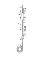
カテーテル10が持続注入腹膜透析に用いられる場合の、腹膜100におけるカテーテル10の一般的な配置を示す図5Aをこれより参照、説明する。ディフューザ30は腹膜38のすぐ遠位側に配置される。長内腔14のコイル状の遠位端領域22は、腹膜100の低位ダグラス腔92に配置される。使用時には、カテーテル10は透析液42の送達と戻しとを分離する。結果として、使用済みの透析液42の再循環は最小になる。使用時には、新鮮な透析液42はディフューザ30を通って腹膜100に入る。透析液42は、必要な生理的及び化学的なプロセスが生じ、新鮮な透析液を使用済み透析液に変える、腹膜100を通過する。血漿と継続的に再生される透析液溶液42との間で高い溶質濃度勾配を維持する為の高い透析液流量により、一定の腹膜組織内の容量が維持できる。使用済み透析液42は、腹膜100の外に長内腔14の少なくとも1つの開口部26を経て吸引されて戻される。
Reference is now made to FIG. 5A showing the general placement of the
長内腔14の遠位端領域22のコイル状の設計は、腹膜100の壁側板と臓側板とを分離するバルクチュービング(かさばるようにチューブを入れること)を増大させるので、使用済み透析液42の流出の為の少なくとも1つの遠位開口部26を壁側板と臓側板とが塞ぐことを防止できる。複数個の開口部26を用いることで流出量を増加することができる。長内腔14のコイル状の遠位端領域22を用いることは、直線状の内腔の先端を用いるよりは内臓に優しいことから、腹膜透析に好ましい。
The coiled design of the
カテーテル10、10’は、好ましくは、硬度測定計値の低いシリコンから作られる。しかしながら、ポリウレタン或いは当技術分野で既知の或いは今後開発される他の生体適合性の材料を用いても良い。硬度測定計値の低いシリコンは、その生体適合性及び、比較的柔軟な体組織である腹膜100での使用に有益な柔軟性の観点から、望ましい。更に、硬度測定計値の低いシリコンは、広範囲の温度状況において柔軟性があり、臨床上有害な浸出し得る可塑剤を有さない。
第1内腔12、第2内腔14、及び2つより多い内腔を有するカテーテル内の補助内腔、及びディフューザ30は、生体適合性の合成樹脂或いはエラストマー、より好ましくは生体適合性のエラストマーで作られても良い。適切な生体適合性の合成樹脂としては、例えば、ポリエチレン、エチレン酢酸ビニル共重合体等の酢酸ビニルの単独重合体(homopolymers)及び共重合体(copolymers)、ポリ塩化ビニル、ポリメタクリル酸メチル等のアクリレーツの単独重合体及び共重合体、ポリメタクリル酸エチル、ポリメタクリル酸塩、エチレングリコールジメタクリル酸塩、エチレンジメタクリル酸塩及びヒドロキシメチルメタクリル酸塩、ポリウレタン、ポリビニルピロリドン、2?ピロリドン、ポリアクリロニトリル系ブタジエン、ポリカーボネート、ポリアミド、ポリテトラフルオロエチレン及びポリ弗化ビニルの単独重合体及び共重合体等のフルオロポリマー、ポリスチレン、スチレンアクリロニトリルの単独重合体及び共重合体、酢酸セルロース、アクリロニトリルブタジエンスチレンの単独重合体及び共重合体、ポリメチルペンテン、ポリスルホン、ポリエステル、ポリイミド、ポリイソブチレン、ポリメチルスチレン及び当業者に既知の他の同様な化合物等の材料を含む。これらの可能性のある生体適合性のポリマーは例示目的で上記に含まれたのであって、制限事項と解釈されるべきではないことは言うまでもない。カテーテル10、10’を形成する為に生体適合性の高分子材料が用いられる場合、高分子材料がポリウレタン或いは、以下に指定されるように、なるべく柔軟な硬度測定計値を有するポリオレフィン高分子材料を含むことが最も好ましい。
The
カテーテル10、10’の形成に用いられるのに適切且つ好ましい生体適合性のエラストマーは、医療用級のシリコンゴム、ポリ塩化ビニル系エラストマー、ポリオレフィンの単独重合体及び共重合体系エラストマー、ウレタンベースのエラストマー、及び天然ゴム或いは他の合成ゴム等の生体適合性のエラストマーを含む。カテーテル10、10は、柔軟性に富み、耐久性があり、柔らかく、且つカテーテルを挿入する領域及び/或いは皮下領域の形状に容易に適合でき、血管壁への損傷の危険性を最小化できるようなエラストマー材料から作られても良い。カテーテル10、10’が血液透析用途に用いられる場合、ショアー押込硬度計の尺度で少なくとも約80−Aの硬さを有するソフトシリコンエラストマーで形成されても良い。このようなエラストマーは、ダウ・コーニング(Dow Corning)から入手可能であり、放射線不透過性を提供する為にエラストマーに20%硫酸バリウムを含むことができる。生体適合性のエラストマーを、特に血液透析に対して用いる場合、より高いショアー押込硬度計値を有するのが好ましいが、当発明の思想から逸脱することなく、より低いショアー押込硬度計値を有するエラストマーから装置を作ることも可能である。この開示に基づき、カテーテル10、10’はその意図される用途次第で更に放射線不透過性であっても良いことは言うまでもない。
Suitable and preferred biocompatible elastomers for use in forming the
随意であるハブ50を有する当発明を示す図2B、図2C、図2D、図3、図5C、図5D及び図6Aから図6Cをこれより参照、説明する。ハブ50が提供される場合、少なくとも2つの内腔12、14の近位端16、18はハブ50内に配置される。内腔12、14は、図2Bに見られるように、着脱不可能な状態でハブ50に取り付けられても良い。あるいは、内腔12、14は、図2Cに見られるように、着脱可能なハブ50’に取り付けられても良い。着脱可能なハブは、係属中の出願であり、「着脱可能なハブ」と題され、本願に引用して援用する米国仮出願整理番号第60/329,593号において開示されている。更に、図2D及び図3で図示されるように、当技術分野で現在既知の或いは今後発見される全てのハブ110を用いることは当発明の範囲内にある。しかしながら、図2Aで図示されるように、ハブは随意であり、例示目的で含まれたハブは制限事項と解釈されるべきではない。本発明のカテーテル10、10’がハブ50と一緒に用いられても、着脱可能なハブ50’と一緒に用いられても、ハブ無しでも、或いはハブ110、或いは当技術分野で現在既知の或いは今後発見される他のアタッチメント110と一緒に用いられても良いことを、当業者は正しく認識するであろう。
Reference is now made to FIGS. 2B, 2C, 2D, 3, 5C, 5D and 6A-6C illustrating the present invention with an
当発明の実施例において、図2B、図5C、図5D及び図6Aから図6Cに見られるように、取り外し不可能なハブ50を利用しても良い。これらの図に見られるように、少なくとも2つの内腔12、14の近位端16、18はハブ50内で終わる。更に、エキステンダ56、58の遠位端も同様にハブ50内で終わる。この実施例では、内腔12、14が「D」字形である場合、内腔12、14の近位端開口部102、104はそれぞれ「D」字形である。更に、図6Aから図6Cに図示される実施例に見られるように、エキステンダ56、58の遠位開口部106、108は、それぞれ円形を有していても良い。少なくとも2つの内腔12、14の延長遠位端開口部106、108及び近位端開口部102、104は、ハブ50に成形されたハブ通路52、54を媒介して相互間で液体を通すようにされる。ハブ50は、一端が円形で他端が「D」字形である取り外し可能な内部ピン(図示しない)の周囲に成形される。ハブ50と一緒に利用される内腔及びエキステンダの形状、サイズ及び数は例示であり、限定事項を意図するものではない。延長近位端(図示しない)は、好ましくはそれぞれのメス型ルアーロックに従来の方法で接続される。このように決定した場合、メス型ルアーロックは、いかなる好適な種類の簡易接続具類、フェルール接合具、挿通可能な接合具、或いはカテーテル10、10’を通した物質の流出入を達成する為の当技術分野で既知の或いは今後発見されるいかなる接続手段に取り替えても良い。エキステンダは、当技術分野で既知であるように、透析装置、他の液体移送器具、或いはカテーテル10、10’の目的を果たす為に必要な他の装置のそれぞれの液体吸引口及び流出口に液体を通すように接続されても良い。
In embodiments of the present invention, a
前述した様に、ハブ50、50’及びカテーテル10、10’とエキステンダ56、58は随意である。本発明のカテーテル10、10’は単に少なくとも2つの内腔12、14だけで形成することができる。ハブ或いは追加のエキステンダが無い内腔の近位端16、18にルアー或いは他の接合具を提供することによって、内腔の近位端16、18が透析装置或いは他の装置に接続可能となる。
As described above, the
カテーテル10、10’が着脱不可能なハブ50を有する場合、概して、ハブ50はカテーテルのユーザの体内の皮下層48を通過可能である。図5C及び図5Dに見られるように、近位端16、18、ハブ50及びエキステンダ56、58を、種々のトンネル技術を用いて体内の皮下層48の皮下トンネルに貫通させても良い。近位端16、18、ハブ50及びエキステンダ56、58は、トンネル入口切開部86に挿入され皮下層48をトンネル出口切開部88へと潜り抜けさせても良い。あるいは、内腔近位端16、18、ハブ50及びエキステンダ56、58は、カテーテル入口切開部40に挿入され皮下層48をトンネル出口切開部86へと潜り抜けさせても良い。同様な手法で、ハブを有さない或いは着脱可能なハブ50’を有するカテーテル10、10’では、内腔近位端16、18を皮下を潜り抜けさせても良い。
If the
随意である、少なくとも1つのカフ44を含むことを図示する図2Aから図2D、図3、図4及び図5Aから図5Dをこれより参照、説明する。更に、随意である第2カフ46も含んでも良い。当技術分野で既知のように、少なくとも1つのカフ44は、カテーテル10、10’をユーザの体に固定する為にカテーテルのユーザの組織がその上に成長し得る材料、概してポリエステル、から作られている。カフ44は、カテーテル10,10’が持続注入腹膜透析に用いられる場合、腹膜38のすぐ近位に配置される。カフ44は、腹膜38から0から5mmの間の近位に配置されても良い。カテーテル10、10’の切開場所で腹膜38が縫合される場合、縫合が引っ張られる際に薄膜38に皺壁を作る可能性がある為、付加的なゆとりが必要となる可能性がある。好ましくは、ディフューザ30とカフ44との間の空間は0.5から10mmの間の範囲にある。第1カフ44と第2カフ46との間の距離の範囲は、好ましくは10cmである。カフ44、46の寸法は、異なるカテーテルのサイズ、実施例、及びカテーテルのユーザ特有の異なる特徴によって変動し得ることは言うまでもない。列挙した寸法は限定事項を意図するものではなく、むしろ例示目的で含まれる。
Reference is now made to FIGS. 2A through 2D, 3, 4, and 5A through 5D, which illustrate the inclusion of at least one
図5Cに見られるように、第2カフ46はカテーテル10、10’の為の出口孔86からは遠位側に皮下に配置されても良い。
As seen in FIG. 5C, the second cuff 46 may be placed subcutaneously distally from the exit aperture 86 for the
本発明の持続注入腹膜透析方法のフローチャートである図7をこれより参照、説明する。この方法はユーザの体に切開部を作り腹膜に行きあたるまで生体組織層を分離すること62;腹膜に円形の縫合をすること64;流出内腔の中の半硬質のワイヤーに誘導されて腹膜のダグラス腔にカテーテルの遠位端を挿入し68、腹膜の円形縫合を締め付けることによりディフューザとカフとの間の壁側腹膜を締めつけること70を含む。また、この方法は、注射器で皮下から腹膜の表面まで麻酔をかけること60を含んでも良い。更に、この方法は、ユーザの皮膚に側方切開部を作ること72;皮膚トンネルとしても知られている皮下トンネルを作ること74;トンネルを掘る手段によって達成し得る、皮下トンネルを通って皮下にカテーテルの遠位端を貫通させること76;内腔に接続アタッチメントを接続すること78;及び皮膚の切開部を縫合すること80、も含んでも良い。
Reference is now made to FIG. 7 which is a flowchart of the continuous infusion peritoneal dialysis method of the present invention. This method makes an incision in the user's body and separates the biological tissue layer until it reaches the peritoneum 62; a circular suture on the
当方法はディフューザ30を有するカテーテル10を提供することも含んでも良い。
The method may also include providing a
ステップ62の切開部は長さ約3cmで、ステップ72の切開部は長さ約10cmであっても良い。切開部の寸法は異なるカテーテルのサイズ、実施例、及びカテーテルのユーザ特有の異なる特徴によって変動し得ることは言うまでもない。列挙した寸法は限定事項を意図するものではなく、むしろ例示目的で含まれる。 Incision of step 62 is about 3cm long, incision of Step 7 2 may be about 10cm long. Of course, the size of the incision may vary depending on different catheter sizes, embodiments, and different user-specific features of the catheter. The dimensions listed are not intended to be limiting, but rather are included for illustrative purposes.
当技術分野で一般に既知であるように、カテーテル10を体内に挿入する前にシース(図示しない)をディフューザに被せるように挿入しても良い。ディフューザ30は、好ましくは硬度測定計値の低いシリコンから作られている為、随意のシース内に容易に圧縮され得る。シースはディフューザ30の容量を漸減させ、この結果、シースを用いない場合に見込まれる大きさの切開部より小さい切開部を利用してディフューザ30を含むカテーテル10の挿入を可能にする。クイル・シース(Quill seath)が当技術分野では一般に既知であり、ハブを有さないカテーテル10で用いられても良い。カテーテル10が取り外し不可能なハブ50を有する場合、当技術分野で一般に既知であるはぎ取り式のシースを用いても良い。
As is generally known in the art, a sheath (not shown) may be inserted over the diffuser before inserting the
着脱不可能なハブ50を有するカテーテル10、10’が、皮膚トンネルを皮下を通って貫通した場合76、皮下層48はハブ50を通過可能にする為に引き延ばされなければならない。通常、皮下層48の弾力性は、ハブ50の通過後に皮下組織が内腔12、14を封入できる程度である。着脱可能なハブ50’がカテーテル10、10’で利用される場合、ハブ50’はカテーテルにアタッチメントを接続するステップ78中に、カテーテルに接続されるアタッチメントの一つである。
If a
当技術分野で既知のように、ルアーロックの開口端が、透析を開始する為に、透析装置或いは他の液体移送器具のそれぞれの吸引口及び流出口に液体を通すように接続されても良い。 As known in the art, the open end of the luer lock may be connected to allow liquid to pass through the respective suction and outlet ports of the dialysis machine or other liquid transfer device to initiate dialysis. .
本発明を種々の実施例によって説明且つ図示したが、あきらかに本発明の範囲内に収まる変更及び修整が可能なことは当業者に明らかであろう。従って、本発明は添付請求の範囲で定義される本発明の精神及び範囲内で広く保護を受けるものである。 While the invention has been described and illustrated by various embodiments, it will be apparent to those skilled in the art that changes and modifications may be made that fall within the scope of the invention. Accordingly, the invention is subject to broad protection within the spirit and scope of the invention as defined by the appended claims.
10 カテーテル
10’ カテーテル
12 第1内腔(短内腔)
14 第2内腔(長内腔)
16 近位端
18 近位端
20 遠位端領域
22 遠位端領域
24 開口部
26 開口部
30 ディフューザ
32 内側部分
34 外側部分
36 開口部
40 腹膜腔
42 物質
44 カフ
46 第2カフ
48 皮下層
50 ハブ
50’ ハブ
52 ハブ通路
54 ハブ通路
56 エキステンダ
58 エキステンダ
82 近位接着領域
84 遠位接着領域
86 トンネル入口切開部
88 トンネル出口切開部
90 内腔壁
92 低位ダグラス腔
96 遠位端
94 放射線不透過性の条片
98 側方
100 腹膜
102 近位端開口部
104 近位端開口部
106 遠位開口部
108 遠位開口部
110 ハブ
112 長手方向の内腔通路
10 Catheter 10 '
14 Second lumen (long lumen)
16
Claims (32)
Applications Claiming Priority (3)
| Application Number | Priority Date | Filing Date | Title |
|---|---|---|---|
| US32751501P | 2001-10-05 | 2001-10-05 | |
| US10/057,340 US6749580B2 (en) | 2001-10-05 | 2002-01-23 | Catheter |
| PCT/US2002/031720 WO2003030960A2 (en) | 2001-10-05 | 2002-10-04 | Catheter for peritoneal dialysis |
Related Child Applications (1)
| Application Number | Title | Priority Date | Filing Date |
|---|---|---|---|
| JP2009028732A Division JP4295355B2 (en) | 2001-10-05 | 2009-02-10 | Compressible diffuser |
Publications (3)
| Publication Number | Publication Date |
|---|---|
| JP2005505353A JP2005505353A (en) | 2005-02-24 |
| JP2005505353A5 JP2005505353A5 (en) | 2006-01-05 |
| JP4288165B2 true JP4288165B2 (en) | 2009-07-01 |
Family
ID=26736364
Family Applications (2)
| Application Number | Title | Priority Date | Filing Date |
|---|---|---|---|
| JP2003533991A Expired - Lifetime JP4288165B2 (en) | 2001-10-05 | 2002-10-04 | Peritoneal dialysis catheter |
| JP2009028732A Expired - Lifetime JP4295355B2 (en) | 2001-10-05 | 2009-02-10 | Compressible diffuser |
Family Applications After (1)
| Application Number | Title | Priority Date | Filing Date |
|---|---|---|---|
| JP2009028732A Expired - Lifetime JP4295355B2 (en) | 2001-10-05 | 2009-02-10 | Compressible diffuser |
Country Status (8)
| Country | Link |
|---|---|
| US (1) | US6749580B2 (en) |
| EP (3) | EP1432462B1 (en) |
| JP (2) | JP4288165B2 (en) |
| AT (1) | ATE509647T1 (en) |
| AU (1) | AU2002341967A1 (en) |
| ES (1) | ES2643217T3 (en) |
| PT (1) | PT2292285T (en) |
| WO (1) | WO2003030960A2 (en) |
Families Citing this family (81)
| Publication number | Priority date | Publication date | Assignee | Title |
|---|---|---|---|---|
| US6702789B1 (en) | 1997-03-11 | 2004-03-09 | Alcove Medical, Inc. | Catheter having insertion control mechanism and anti-bunching mechanism |
| US6976973B1 (en) * | 2000-10-12 | 2005-12-20 | Baxter International Inc. | Peritoneal dialysis catheters |
| US6911014B2 (en) * | 2001-10-05 | 2005-06-28 | Medical Components, Inc. | Continuous flow peritoneal dialysis catheter |
| US6758836B2 (en) | 2002-02-07 | 2004-07-06 | C. R. Bard, Inc. | Split tip dialysis catheter |
| US6893414B2 (en) * | 2002-08-12 | 2005-05-17 | Breg, Inc. | Integrated infusion and aspiration system and method |
| ATE391524T1 (en) * | 2002-11-15 | 2008-04-15 | Radius Int Lp | CATHETER |
| US7393339B2 (en) | 2003-02-21 | 2008-07-01 | C. R. Bard, Inc. | Multi-lumen catheter with separate distal tips |
| US20040243095A1 (en) | 2003-05-27 | 2004-12-02 | Shekhar Nimkar | Methods and apparatus for inserting multi-lumen spit-tip catheters into a blood vessel |
| EP1663375A4 (en) * | 2003-09-08 | 2007-04-04 | Ash Access Technology Inc | Anti-clotting indwelling catheter |
| US7594910B2 (en) | 2004-03-18 | 2009-09-29 | C. R. Bard, Inc. | Catheter connector |
| US8083728B2 (en) | 2004-03-18 | 2011-12-27 | C. R. Bard, Inc. | Multifunction adaptor for an open-ended catheter |
| US7594911B2 (en) | 2004-03-18 | 2009-09-29 | C. R. Bard, Inc. | Connector system for a proximally trimmable catheter |
| US7377915B2 (en) | 2004-04-01 | 2008-05-27 | C. R. Bard, Inc. | Catheter connector system |
| US8992454B2 (en) | 2004-06-09 | 2015-03-31 | Bard Access Systems, Inc. | Splitable tip catheter with bioresorbable adhesive |
| US20060004316A1 (en) | 2004-07-02 | 2006-01-05 | Difiore Attilio E | Reduction of recirculation in catheters |
| US7976518B2 (en) | 2005-01-13 | 2011-07-12 | Corpak Medsystems, Inc. | Tubing assembly and signal generator placement control device and method for use with catheter guidance systems |
| US9126011B2 (en) * | 2006-03-24 | 2015-09-08 | Merit Medical Systems, Inc. | Anti-clotting indwelling catheter |
| US7875019B2 (en) | 2005-06-20 | 2011-01-25 | C. R. Bard, Inc. | Connection system for multi-lumen catheter |
| US20070066964A1 (en) * | 2005-07-27 | 2007-03-22 | Atkins Joseph R | Catheter and Tunneling Device Therefor |
| US20070078478A1 (en) * | 2005-07-27 | 2007-04-05 | Atkins Joseph R | Catheter and tunneling device therefor |
| US8029457B2 (en) | 2006-03-24 | 2011-10-04 | Aat Catheter Technologies, Llc | Indwelling catheter with anti-clotting features |
| DE602007004718D1 (en) | 2006-03-31 | 2010-03-25 | Bard Inc C R | Catheter with arched transition area |
| US20080082079A1 (en) | 2006-09-28 | 2008-04-03 | Tyco Healthcare Group Lp | Low profile catheter assembly |
| US9168355B2 (en) * | 2006-09-29 | 2015-10-27 | Covidien Lp | Acute hemodialysis catheter assembly |
| EP2173412A4 (en) * | 2007-07-06 | 2011-07-27 | Allievion Medical Inc | Constrained fluid delivery device |
| US20090018493A1 (en) * | 2007-07-10 | 2009-01-15 | Ash Stephen R | Implantable catheter assembly |
| EP3124061B1 (en) * | 2007-07-27 | 2018-06-20 | Fresenius Medical Care Holdings, Inc. | Systems and methods for delivery of peritoneal dialysis (pd) solutions |
| WO2009051967A1 (en) | 2007-10-17 | 2009-04-23 | Spire Corporation | Manufacture of split tip catheters |
| US8292841B2 (en) | 2007-10-26 | 2012-10-23 | C. R. Bard, Inc. | Solid-body catheter including lateral distal openings |
| US8066660B2 (en) | 2007-10-26 | 2011-11-29 | C. R. Bard, Inc. | Split-tip catheter including lateral distal openings |
| JP5452498B2 (en) | 2007-11-01 | 2014-03-26 | シー・アール・バード・インコーポレーテッド | Catheter assembly including triple lumen end |
| US9579485B2 (en) | 2007-11-01 | 2017-02-28 | C. R. Bard, Inc. | Catheter assembly including a multi-lumen configuration |
| US8211053B2 (en) * | 2008-05-13 | 2012-07-03 | Equilibrate, Llc | Interosmolar fluid removal |
| JP2009273609A (en) | 2008-05-14 | 2009-11-26 | Nippon Sherwood Medical Industries Ltd | Catheter with valve |
| EP2123706A1 (en) * | 2008-05-19 | 2009-11-25 | Evonik Degussa GmbH | Thermoplastic elastomers |
| US9005154B2 (en) * | 2008-09-26 | 2015-04-14 | Covidien Lp | Valved hemodialysis catheter |
| WO2010151825A1 (en) | 2009-06-26 | 2010-12-29 | C. R. Bard, Inc. | Proximally trimmable catheter including pre-attached bifurcation and related methods |
| JP2011050420A (en) * | 2009-08-31 | 2011-03-17 | Nippon Sherwood Medical Industries Ltd | Valved catheter |
| CA2715857A1 (en) | 2009-09-30 | 2011-03-30 | Tyco Healthcare Group Lp | Medical catheter having a design providing low recirculation and reversibility |
| US9034191B2 (en) | 2010-02-24 | 2015-05-19 | The Regents Of The University Of Michigan | Vibration-assisted dialysis method |
| US9265913B2 (en) | 2010-09-22 | 2016-02-23 | Vital 5, Llc | Catheter assembly |
| US9446224B2 (en) | 2010-09-22 | 2016-09-20 | Vital 5, L.L.C. | Barrier catheter |
| US9717883B2 (en) | 2011-02-10 | 2017-08-01 | C. R. Bard, Inc. | Multi-lumen catheter with enhanced flow features |
| WO2012109462A2 (en) | 2011-02-10 | 2012-08-16 | C. R. Bard, Inc. | Multi-lumen catheter including an elliptical profile |
| JP5713732B2 (en) | 2011-03-08 | 2015-05-07 | 日本コヴィディエン株式会社 | Catheter with valve |
| US9861733B2 (en) | 2012-03-23 | 2018-01-09 | Nxstage Medical Inc. | Peritoneal dialysis systems, devices, and methods |
| CN103619372A (en) | 2011-03-23 | 2014-03-05 | 纳科斯达格医药股份有限公司 | Peritoneal dialysis system, device and method |
| US9028441B2 (en) | 2011-09-08 | 2015-05-12 | Corpak Medsystems, Inc. | Apparatus and method used with guidance system for feeding and suctioning |
| USD679804S1 (en) | 2011-09-22 | 2013-04-09 | Vital 5, Llc | Catheter |
| US8747343B2 (en) | 2011-09-30 | 2014-06-10 | Covidien Lp | Hemodialysis catheter with improved side opening design |
| US9072867B2 (en) | 2011-09-30 | 2015-07-07 | Covidien Lp | Catheter with external flow channel |
| US8845590B2 (en) * | 2012-05-01 | 2014-09-30 | Merit Medical Systems, Inc. | Catheter with distal diffuser |
| US10143822B2 (en) | 2012-07-05 | 2018-12-04 | Covidien Lp | Valved tip catheters |
| US10456518B2 (en) * | 2012-08-03 | 2019-10-29 | National University Of Singapore | Arterial cannula which allows perfusion along opposing directions within a cannulated vessel |
| US9155862B2 (en) | 2012-09-28 | 2015-10-13 | Covidien Lp | Symmetrical tip acute catheter |
| US10252023B2 (en) | 2013-01-11 | 2019-04-09 | C. R. Bard, Inc. | Curved catheter and methods for making same |
| US20140200402A1 (en) | 2013-01-16 | 2014-07-17 | Phillip Jack Snoke | Medical Device Introduction Systems and Methods |
| US20170055813A1 (en) | 2013-01-16 | 2017-03-02 | Uvision 360, Inc. | Medical device introduction and imaging system, and associated method |
| USD748252S1 (en) | 2013-02-08 | 2016-01-26 | C. R. Bard, Inc. | Multi-lumen catheter tip |
| CN103191478B (en) * | 2013-04-17 | 2015-07-29 | 江苏康进医疗器材有限公司 | The two bag peritoneal dialysis of doubly-linked is with two-tube |
| EP3132751B1 (en) * | 2014-05-08 | 2020-01-29 | Nikkiso Co., Ltd. | Suction apparatus for body cavity fluid perfusion system |
| WO2016011091A1 (en) | 2014-07-14 | 2016-01-21 | C. R. Bard, Inc. | Apparatuses, systems, and methods for inserting split tip catheters having enhanced stiffening and guiding features |
| EP3215211A4 (en) | 2014-11-07 | 2018-07-04 | C. R. Bard, Inc. | Connection system for tunneled catheters |
| CN104383620A (en) * | 2014-11-20 | 2015-03-04 | 上海交通大学医学院附属新华医院 | Novel dual-channel peritoneal dialysis catheter suitable for operation under endoscope |
| US10512713B2 (en) | 2015-07-20 | 2019-12-24 | Strataca Systems Limited | Method of removing excess fluid from a patient with hemodilution |
| US10918827B2 (en) | 2015-07-20 | 2021-02-16 | Strataca Systems Limited | Catheter device and method for inducing negative pressure in a patient's bladder |
| US11040172B2 (en) | 2015-07-20 | 2021-06-22 | Strataca Systems Limited | Ureteral and bladder catheters and methods of inducing negative pressure to increase renal perfusion |
| US11229771B2 (en) | 2015-07-20 | 2022-01-25 | Roivios Limited | Percutaneous ureteral catheter |
| RU2720403C2 (en) | 2015-07-20 | 2020-04-29 | Стратака Системз Лимитед, Мт | Ureteral catheter and urinary bladder and methods of creating negative pressure to increase renal perfusion |
| US11541205B2 (en) | 2015-07-20 | 2023-01-03 | Roivios Limited | Coated urinary catheter or ureteral stent and method |
| US10493232B2 (en) | 2015-07-20 | 2019-12-03 | Strataca Systems Limited | Ureteral catheters, bladder catheters, systems, kits and methods for inducing negative pressure to increase renal function |
| US11040180B2 (en) | 2015-07-20 | 2021-06-22 | Strataca Systems Limited | Systems, kits and methods for inducing negative pressure to increase renal function |
| US10926062B2 (en) | 2015-07-20 | 2021-02-23 | Strataca Systems Limited | Ureteral and bladder catheters and methods of inducing negative pressure to increase renal perfusion |
| US9861734B2 (en) * | 2016-03-21 | 2018-01-09 | King Saud University | Bifurcated peritoneal catheter |
| US10500331B2 (en) | 2017-08-18 | 2019-12-10 | Ayman H. Al-Jazaeri | Drainage catheter with retractable internal drains |
| US11896782B2 (en) | 2017-08-23 | 2024-02-13 | C. R. Bard, Inc. | Priming and tunneling system for a retrograde catheter assembly |
| US10758214B2 (en) | 2017-11-13 | 2020-09-01 | UVision360, Inc. | Biopsy device and method |
| AU2019228526B2 (en) | 2018-02-28 | 2021-11-25 | Nxstage Medical, Inc. | Fluid preparation and treatment devices, methods, and systems |
| US10863886B2 (en) | 2019-05-03 | 2020-12-15 | UVision360, Inc. | Rotatable introducers |
| US10765847B1 (en) | 2019-12-10 | 2020-09-08 | Ayman H. Al-Jazaeri | Single lumen drainage catheter with extendable and retractable drains |
| CN113877017B (en) * | 2021-11-05 | 2023-10-20 | 胡梦思 | Peritoneal dialysis puts tub fixing device |
Family Cites Families (27)
| Publication number | Priority date | Publication date | Assignee | Title |
|---|---|---|---|---|
| US3707967A (en) | 1970-10-01 | 1973-01-02 | Tecna Corp | Steady flow regenerative peritoneal dialysis system and method |
| US3981299A (en) * | 1971-03-15 | 1976-09-21 | Harry Elmer Murray | Urethral catheter |
| US4437856A (en) | 1981-02-09 | 1984-03-20 | Alberto Valli | Peritoneal catheter device for dialysis |
| US4671795A (en) | 1984-11-19 | 1987-06-09 | Mulchin William L | Permanent/retrievable ureteral catheter |
| US4941872A (en) | 1985-01-22 | 1990-07-17 | C. R. Bard, Inc. | Control handle for surgical irrigation and suction device |
| US4681564A (en) | 1985-10-21 | 1987-07-21 | Landreneau Michael D | Catheter assembly having balloon extended flow path |
| US4925452A (en) * | 1988-03-08 | 1990-05-15 | Uresil Corporation | Multiple conduit drainage device |
| US4935004A (en) | 1988-12-20 | 1990-06-19 | Henry Ford Health System | Peritoneal dialysis catheter |
| US5057075A (en) | 1989-12-13 | 1991-10-15 | Moncrief Jack W | Method for implanting a catheter |
| US5146916A (en) * | 1990-01-05 | 1992-09-15 | Catalani Angelo S | Endotracheal tube incorporating a drug-irrigation device |
| AU7253691A (en) * | 1990-01-08 | 1991-08-05 | Curators Of The University Of Missouri, The | Multiple lumen catheter for hemodialysis |
| US5322521A (en) * | 1990-05-30 | 1994-06-21 | Wilk Peter J | Plume evacuation method |
| US5143062A (en) | 1990-10-26 | 1992-09-01 | Mallinckrodt Medical, Inc. | Endotracheal tube having irrigation means |
| US5458582A (en) * | 1992-06-15 | 1995-10-17 | Nakao; Naomi L. | Postoperative anesthetic delivery device and associated method for the postoperative treatment of pain |
| JP3146332B2 (en) * | 1992-12-24 | 2001-03-12 | 允 石崎 | CAPD catheter |
| US5254084A (en) | 1993-03-26 | 1993-10-19 | Geary Gregory L | Peritoneal catheter device for dialysis |
| US5607462A (en) | 1993-09-24 | 1997-03-04 | Cardiac Pathways Corporation | Catheter assembly, catheter and multi-catheter introducer for use therewith |
| US5599304A (en) * | 1994-05-10 | 1997-02-04 | Mount Sinai School Of Medicine Of The City University Of New York | Sinonasal suction apparatus |
| FR2738154B1 (en) | 1995-09-05 | 1997-12-26 | Pourchez Thierry | MULTI-PIPE CATHETER, ESPECIALLY HEMODIALYSIS |
| NL1003226C2 (en) | 1996-05-29 | 1997-12-03 | Cordis Europ | Suction catheter with preformed end section. |
| WO1998017333A2 (en) | 1996-10-22 | 1998-04-30 | Hemocleanse, Inc. | Continuous flow-through peritoneal dialysis (cfpd) method with control of intraperitoneal pressure |
| US5776111A (en) | 1996-11-07 | 1998-07-07 | Medical Components, Inc. | Multiple catheter assembly |
| US6179827B1 (en) * | 1998-03-16 | 2001-01-30 | Chase Medical | Catheter having integral expandable/collapsible lumen |
| US6245039B1 (en) | 1998-10-05 | 2001-06-12 | Vasca, Inc. | Methods and apparatus for performing flow-through peritoneal dialysis |
| US6241710B1 (en) | 1999-12-20 | 2001-06-05 | Tricardia Llc | Hypodermic needle with weeping tip and method of use |
| US6497676B1 (en) * | 2000-02-10 | 2002-12-24 | Baxter International | Method and apparatus for monitoring and controlling peritoneal dialysis therapy |
| US6976973B1 (en) * | 2000-10-12 | 2005-12-20 | Baxter International Inc. | Peritoneal dialysis catheters |
-
2002
- 2002-01-23 US US10/057,340 patent/US6749580B2/en not_active Expired - Lifetime
- 2002-10-04 EP EP02776128A patent/EP1432462B1/en not_active Expired - Lifetime
- 2002-10-04 EP EP10010960.2A patent/EP2292285B1/en not_active Expired - Lifetime
- 2002-10-04 AT AT02776128T patent/ATE509647T1/en not_active IP Right Cessation
- 2002-10-04 WO PCT/US2002/031720 patent/WO2003030960A2/en active Application Filing
- 2002-10-04 AU AU2002341967A patent/AU2002341967A1/en not_active Abandoned
- 2002-10-04 JP JP2003533991A patent/JP4288165B2/en not_active Expired - Lifetime
- 2002-10-04 PT PT100109602T patent/PT2292285T/en unknown
- 2002-10-04 EP EP10010959A patent/EP2289576A1/en not_active Withdrawn
- 2002-10-04 ES ES10010960.2T patent/ES2643217T3/en not_active Expired - Lifetime
-
2009
- 2009-02-10 JP JP2009028732A patent/JP4295355B2/en not_active Expired - Lifetime
Also Published As
| Publication number | Publication date |
|---|---|
| JP4295355B2 (en) | 2009-07-15 |
| AU2002341967A1 (en) | 2003-04-22 |
| EP2289576A1 (en) | 2011-03-02 |
| EP1432462A4 (en) | 2007-07-11 |
| EP2292285B1 (en) | 2017-07-12 |
| ATE509647T1 (en) | 2011-06-15 |
| US20030069534A1 (en) | 2003-04-10 |
| EP2292285A1 (en) | 2011-03-09 |
| PT2292285T (en) | 2017-10-19 |
| EP1432462B1 (en) | 2011-05-18 |
| ES2643217T3 (en) | 2017-11-21 |
| WO2003030960A2 (en) | 2003-04-17 |
| EP1432462A2 (en) | 2004-06-30 |
| US6749580B2 (en) | 2004-06-15 |
| JP2005505353A (en) | 2005-02-24 |
| JP2009101207A (en) | 2009-05-14 |
| WO2003030960A3 (en) | 2004-03-11 |
Similar Documents
| Publication | Publication Date | Title |
|---|---|---|
| JP4288165B2 (en) | Peritoneal dialysis catheter | |
| JP4852533B2 (en) | Continuous flow peritoneal dialysis catheter | |
| AU2002240049B2 (en) | Multi-lumen catheter with attachable hub | |
| JP3189974B2 (en) | catheter | |
| US4626240A (en) | Dual lumen subclavian cannula | |
| US6074377A (en) | Method of installing vascular access device | |
| US5360397A (en) | Hemodiaylsis catheter and catheter assembly | |
| CA1267344A (en) | Medical tube device | |
| TW510804B (en) | Peritoneal dialysis catheters | |
| EP0691866B1 (en) | Balloon catheter and device for perfusion with the balloon catheter | |
| JP4979691B2 (en) | Extracorporeal treatment catheter port assembly | |
| US8137316B2 (en) | Sheathless insertion stylet system for catheter placement | |
| US20060271012A1 (en) | Catheter port assembly for extracorporeal treatment | |
| WO2004030738A1 (en) | Multi-lumen catheter with attachable hub | |
| WO2005016432A1 (en) | Catheter device | |
| JP2001513357A (en) | Separable multi-catheter assembly and method for inserting the same | |
| JP2022119950A (en) | Multi-lumen indwelling catheter | |
| JP4480919B2 (en) | Abdominal-venous shunt catheter | |
| US20210085844A1 (en) | Sterile connector and cannula assembly | |
| JPH02182270A (en) | Catheter |
Legal Events
| Date | Code | Title | Description |
|---|---|---|---|
| A072 | Dismissal of procedure [no reply to invitation to correct request for examination] |
Free format text: JAPANESE INTERMEDIATE CODE: A072 Effective date: 20041214 |
|
| A521 | Request for written amendment filed |
Free format text: JAPANESE INTERMEDIATE CODE: A523 Effective date: 20050921 |
|
| A621 | Written request for application examination |
Free format text: JAPANESE INTERMEDIATE CODE: A621 Effective date: 20050921 |
|
| RD12 | Notification of acceptance of power of sub attorney |
Free format text: JAPANESE INTERMEDIATE CODE: A7432 Effective date: 20050921 |
|
| A521 | Request for written amendment filed |
Free format text: JAPANESE INTERMEDIATE CODE: A821 Effective date: 20050921 |
|
| RD03 | Notification of appointment of power of attorney |
Free format text: JAPANESE INTERMEDIATE CODE: A7423 Effective date: 20070524 |
|
| A131 | Notification of reasons for refusal |
Free format text: JAPANESE INTERMEDIATE CODE: A131 Effective date: 20081111 |
|
| A521 | Request for written amendment filed |
Free format text: JAPANESE INTERMEDIATE CODE: A523 Effective date: 20090210 |
|
| TRDD | Decision of grant or rejection written | ||
| A01 | Written decision to grant a patent or to grant a registration (utility model) |
Free format text: JAPANESE INTERMEDIATE CODE: A01 Effective date: 20090310 |
|
| A01 | Written decision to grant a patent or to grant a registration (utility model) |
Free format text: JAPANESE INTERMEDIATE CODE: A01 |
|
| A61 | First payment of annual fees (during grant procedure) |
Free format text: JAPANESE INTERMEDIATE CODE: A61 Effective date: 20090330 |
|
| FPAY | Renewal fee payment (event date is renewal date of database) |
Free format text: PAYMENT UNTIL: 20120403 Year of fee payment: 3 |
|
| R150 | Certificate of patent or registration of utility model |
Free format text: JAPANESE INTERMEDIATE CODE: R150 |
|
| FPAY | Renewal fee payment (event date is renewal date of database) |
Free format text: PAYMENT UNTIL: 20120403 Year of fee payment: 3 |
|
| FPAY | Renewal fee payment (event date is renewal date of database) |
Free format text: PAYMENT UNTIL: 20130403 Year of fee payment: 4 |
|
| FPAY | Renewal fee payment (event date is renewal date of database) |
Free format text: PAYMENT UNTIL: 20130403 Year of fee payment: 4 |
|
| FPAY | Renewal fee payment (event date is renewal date of database) |
Free format text: PAYMENT UNTIL: 20140403 Year of fee payment: 5 |
|
| R250 | Receipt of annual fees |
Free format text: JAPANESE INTERMEDIATE CODE: R250 |
|
| R250 | Receipt of annual fees |
Free format text: JAPANESE INTERMEDIATE CODE: R250 |
|
| R250 | Receipt of annual fees |
Free format text: JAPANESE INTERMEDIATE CODE: R250 |
|
| R250 | Receipt of annual fees |
Free format text: JAPANESE INTERMEDIATE CODE: R250 |
|
| R250 | Receipt of annual fees |
Free format text: JAPANESE INTERMEDIATE CODE: R250 |
|
| R250 | Receipt of annual fees |
Free format text: JAPANESE INTERMEDIATE CODE: R250 |