JP4286940B2 - NC machining program creation method and apparatus for machine tools - Google Patents
NC machining program creation method and apparatus for machine tools Download PDFInfo
- Publication number
- JP4286940B2 JP4286940B2 JP33818298A JP33818298A JP4286940B2 JP 4286940 B2 JP4286940 B2 JP 4286940B2 JP 33818298 A JP33818298 A JP 33818298A JP 33818298 A JP33818298 A JP 33818298A JP 4286940 B2 JP4286940 B2 JP 4286940B2
- Authority
- JP
- Japan
- Prior art keywords
- tool
- machining
- turning
- program
- program creation
- Prior art date
- Legal status (The legal status is an assumption and is not a legal conclusion. Google has not performed a legal analysis and makes no representation as to the accuracy of the status listed.)
- Expired - Fee Related
Links
Images


Description
【0001】
【発明の属する技術分野】
本発明は、主軸先端のチャックに把持した工作物に対して、工作物を回転させて旋削工具により加工を行うこと、および、工具自体が回転する回転工具により加工を行うことが可能なターニングセンタ等の工作機械のためのNC加工プログラムの作成方法および装置に関するものである。
【0002】
【従来の技術】
主軸先端のチャックに把持した工作物に対して、工作物を回転させて旋削工具により加工を行うこと、および、工具自体が回転する回転工具により加工を行うことが可能なターニングセンタ等の工作機械は公知である。図1は、ターニングセンタの一例を示す斜視図である。
【0003】
ベッド1の上面には、後述する主軸19の軸線方向と平行なZ軸方向に2本のZ軸案内部材2が設けられている。ここでは、Z軸案内部材2は、工作機械が設置される床と平行な水平面内に配置されている。このZ軸案内部材2上には、往復台3がZ軸方向に移動可能に載置されている。往復台3のZ軸方向の移動は、Z軸モータ26によって駆動される。往復台3上には、Y軸送り台7がZ軸線と直交する方向であるY軸方向に移動可能に設けられている。ここでは、Y軸方向も水平面内に配置されている。
【0004】
Y軸送り台7上には、刃物台本体11がX軸方向(垂直方向)に移動可能に設けられている。刃物台本体11上には、複数の工具を円周上に配置したタレット16が設けられている。タレット16は、割り出し回転を行い、必要な工具を加工位置に位置決めする。また、Y軸送り台7上には、自動工具交換装置30が設けられている。さらに、Y軸送り台7上には、工具を貯蔵保管する工具マガジン40が搭載されている。
【0005】
Z軸方向と平行なベッド1の垂直面には、心押台17がZ軸方向に移動可能に設けられている。心押台17と対向する位置には、主軸台18が設けられている。主軸台18内には、主軸19が回転可能に支持されている。主軸19の一端には、チャック(図示せず)が設けられており、他端にはプーリ20が固定されている。一方、主軸駆動モータ23の出力軸には、プーリ22が固定されている。プーリ20とプーリ22との間にVベルト21が架け渡してあり、プーリ20はVベルト21を介して主軸駆動モータ23により回転駆動される。
【0006】
主軸19の回転角度位置は、C軸制御ユニット24により制御される。C軸制御ユニット24は、主軸台18上に載置固定されている。C軸制御ユニット24には、C軸制御モータ25が備えられており、このC軸制御モータ25の回転駆動力により歯車伝導機構を介して主軸19の角度位置を制御する。
【0007】
このようなターニングセンタによれば、主軸19先端のチャックに工作物を把持させて所定の回転数で連続回転させるとともに、タレット16の旋削工具を工作物に対してX,Z軸方向に相対移動させて旋削加工を行うことができる。また、主軸19をC軸方向に制御するとともに、タレット16に設けた回転工具を駆動モータ(図示せず)によって回転させ、工作物に対してX,Y,Z軸方向に相対移動させてミーリング加工、ドリル加工、タップ加工等の回転工具による加工(回転工具加工)を行うことができる。すなわち、工作物の1回のチャッキングで複数の加工工程を行うことができる。
【0008】
このようなターニングセンタにより加工を行うには、NC加工プログラムの作成が必要である。このNC加工プログラムの作成は、旋削加工と回転工具加工の両方のNC加工プログラムがわかる操作者でないと作成が困難であるため、NC加工プログラムを自動的に作成する自動プログラム作成装置あるいは自動プログラム作成機能を備えたNC(数値制御)装置を用いることが多い。
【0009】
このような自動プログラム作成機能には、旋削加工を行うためのNC旋盤用自動プログラム作成機能と、回転工具による加工を行うマシニングセンタ(以下、MCという)用自動プログラム作成機能がある。両者の自動プログラム作成機能では、仕上げ形状データ等の入力方法が異なる。NC加工プログラムそのものに関しても、工作物が回転して加工が行われるNC旋盤用のNC加工プログラムと工具が回転して加工を行うMC用のNC加工プログラムでは、NC指令の意味等も異なっている。
【0010】
【発明が解決しようとする課題】
以上のようなターニングセンタの自動プログラム作成機能によりNC加工プログラムを作成すると、まず旋削加工の部分工程が出力され、続いてミーリング等の回転工具加工の部分工程が出力される。しかしながら、旋削加工の一部の工程の前に、回転工具加工による工程を行ったほうがよい場合がある。図10、図11により、工程の入れ換えが必要な場合の一例を説明する。
【0011】
例えば、工作物Wの外周面に旋削加工を行い、さらに外周面にドリルによる穴開け加工を行う場合、自動プログラム作成機能では、図10のように(a)外径荒加工、(b)外径仕上加工、(c)ドリル加工の順に工程が並べられてNC加工プログラムが作成される。このように回転工具加工であるドリル加工が最後の工程となるため、このNC加工プログラムによってそのまま加工を行うと、図10(c)のように、工作物Wの外周面にバリBが最終的に残ってしまう。
【0012】
これを図11のように、(a)外径荒加工、(b)ドリル加工、(c)外径仕上加工の順に工程を入れ換えて加工を行うと、最後の外径仕上げ加工によってバリBが除去され、望ましい最終加工結果が得られる。このような場合には、自動作成されたNC加工プログラムを、操作者が自動プログラム作成装置あるいはNC装置側で編集して加工工程を入れ換えていたが、熟練者であっても編集操作は容易ではなく、編集ミスや修正もれにより工作機械が誤った加工動作を行ってしまうおそれがあった。
【0013】
そこで、本発明は、ターニングセンタ等の工作機械の自動プログラム作成機能において、自動作成されたNC加工プログラムの各加工工程の順番等を、必要に応じて操作者が簡単に変更することができる工作機械のNC加工プログラムの作成方法および装置を提供することを目的とする。
【0014】
【課題を解決するための手段】
上記目的を達成するために、本発明の工作機械のNC加工プログラム作成方法は、旋削工具による加工すなわち旋削加工と、回転工具による加工すなわち回転工具加工とが可能な工作機械のためのNC加工プログラム作成方法であって、加工を行う素材工作物の形状を入力する手順と、前記旋削加工による仕上げ形状を入力する手順と、前記回転工具加工による仕上げ形状を入力する手順と、前記旋削加工による仕上げ形状を形成するための部分工程である旋削部分工程を1つ以上作成するとともに、前記回転工具加工による仕上げ形状を形成するための部分工程である回転工具部分工程を1つ以上作成し、前記旋削部分工程および前記回転工具部分工程を表示する工程表示手順と、前記工程表示手順で表示した前記旋削部分工程および前記回転工具部分工程の順番の変更を可能とする編集手順と、前記旋削部分工程および前記回転工具部分工程を前記編集手順によって決定された順番に従って連結してNC加工プログラムを作成するとともに、前記旋削部分工程の後に前記回転工具部分工程が続く接続部分に前記旋削加工から前記回転工具加工に加工種類を変更するための複数のNC指令からなる第1の連結プログラムを挿入し、前記回転工具部分工程の後に前記旋削部分工程が続く接続部分に前記回転工具加工から前記旋削加工に加工種類を変更するための複数のNC指令からなる第2の連結プログラムを挿入するプログラム作成手順とを有するものである。
【0015】
また、上記の工作機械のNC加工プログラム作成方法において、前記プログラム作成手順は、前記第1の連結プログラムおよび前記第2の連結プログラムの先頭部に順次異なるシーケンス番号を付与して前記NC加工プログラム内に挿入するものであることが好ましい。
【0017】
また、上記の工作機械のNC加工プログラム作成方法において、前記工程表示手順は、前記旋削部分工程および前記回転工具部分工程に使用する工具を指定するためのタレット工具番号を表示するものであり、前記タレット工具番号を変更可能とする手順を有することが好ましい。
【0018】
また、上記の工作機械のNC加工プログラム作成方法において、前記タレット工具番号は、タレットの工具装着部を指定するタレット面番号と工具を指定する工具番号とを含むものであることが好ましい。
【0019】
また、本発明の工作機械のNC加工プログラム作成装置は、旋削工具による加工すなわち旋削加工と、回転工具による加工すなわち回転工具加工とが可能な工作機械のためのNC加工プログラム作成装置であって、文字または図形を表示可能な表示手段と、操作者がデータを入力するための入力手段と、加工を行う素材工作物の形状のデータを記憶する素材形状記憶手段と、前記旋削加工による仕上げ形状のデータを記憶する旋削工具仕上形状記憶手段と、前記回転工具加工による仕上げ形状のデータを記憶する回転工具仕上形状記憶手段と、前記旋削加工による仕上げ形状を形成するための部分工程である旋削部分工程を1つ以上作成するとともに、前記回転工具加工による仕上げ形状を形成するための部分工程である回転工具部分工程を1つ以上作成し、前記旋削部分工程および前記回転工具部分工程を前記表示手段に表示する工程表示手段と、前記工程表示手段により表示した前記旋削部分工程および前記回転工具部分工程の順番の変更を可能とする工程順序編集手段と、前記旋削部分工程および前記回転工具部分工程を前記工程順序編集手段によって決定された順番に従って連結してNC加工プログラムを作成するとともに、前記旋削部分工程の後に前記回転工具部分工程が続く接続部分に前記旋削加工から前記回転工具加工に加工種類を変更するための複数のNC指令からなる第1の連結プログラムを挿入し、前記回転工具部分工程の後に前記旋削部分工程が続く接続部分に前記回転工具加工から前記旋削加工に加工種類を変更するための複数のNC指令からなる第2の連結プログラムを挿入するプログラム作成手段と、前記第1の連結プログラムおよび前記第2の連結プログラムを記憶する連結プログラム記憶手段とを有するものである。
【0020】
また、上記の工作機械のNC加工プログラム作成装置において、前記プログラム作成手段は、前記第1の連結プログラムおよび前記第2の連結プログラムの先頭部に順次異なるシーケンス番号を付与して前記NC加工プログラム内に挿入するものであることが好ましい。
【0022】
また、上記の工作機械のNC加工プログラム作成装置において、前記工程表示手段は、前記旋削部分工程および前記回転工具部分工程に使用する工具を指定するためのタレット工具番号を表示するものであり、前記タレット工具番号を変更可能とする工具編集手段を有することが好ましい。
【0023】
また、上記の工作機械のNC加工プログラム作成装置において、前記タレット工具番号は、タレットの工具装着部を指定するタレット面番号と工具を指定する工具番号とを含むものであることが好ましい。
【0024】
【発明の実施の形態】
本発明の実施の形態について図面を参照して説明する。図1は、本発明を適用する工作機械としてのターニングセンタの斜視図である。各部材の説明、およびターニングセンタの動作は前述のとおりである。このターニングセンタは、NC装置50(図2参照)によって制御される。また、NC装置50には自動プログラム作成装置60が接続されている。
【0025】
図2は、自動プログラム作成装置60の構成を示すブロック図である。ここでは、自動プログラム作成装置60は、NC装置50と別体に設けられ、NC装置50に接続されるものとしているが、自動プログラム作成装置60をNC装置50内に組み込むようにしてもよい。自動プログラム作成装置60には、種々のデータ処理を行う情報処理手段としてのCPU61が設けられており、CPU61にはバス62を介して主記憶装置としてROM63およびRAM64が接続されている。
【0026】
CPU61は、ROM63に記憶されているシステムプログラムおよびデータと、RAM64にロード(メモリ中に読み込むこと)されたプログラムおよびデータに従って動作する。このようにRAM64にロードされるプログラムとしては、基本プログラムであるOS(オペレーティング・システム)や自動プログラム作成機能を実現するための自動プロ機能用プログラム641、自動プロ機能用プログラム641により作成された各部分工程の順番を変更したりタレット工具番号の編集を行うための結合工程編集プログラム642、表示手段69に対して文字や図形の表示を行う表示制御プログラム等がある。
【0027】
また、CPU61にはバス62を介してパラメータメモリ65が接続されている。パラメータメモリ65には、加工に必要な各種パラメータを記憶しておく。パラメータメモリ65は、不揮発メモリを使用することにより工作機械の電源をオフにしても記憶内容を保持しておくことができる。パラメータメモリ65には、旋削加工のNC加工プログラムと回転工具加工のNC加工プログラムとの間に挿入して各加工工程間の連結を可能とする連結プログラム651のデータが記憶されている。連結プログラム651には、後述するように連結処理Aと連結処理Bの2種類のデータがある。
【0028】
さらに、CPU61にはバス62を介して素材形状メモリ66、旋削工具仕上形状メモリ67、回転工具仕上形状メモリ68が接続されている。素材形状メモリ66には、操作者により入力された素材工作物の形状のデータが記憶される。旋削工具仕上形状メモリ67には、操作者により入力された旋削加工における仕上げ形状のデータが記憶される。回転工具仕上形状メモリ68には、操作者により入力された回転工具加工における仕上げ形状のデータが記憶される。これらの素材形状メモリ66、旋削工具仕上形状メモリ67、回転工具仕上形状メモリ68も、不揮発メモリを使用することにより工作機械の電源をオフにしても記憶内容を保持しておくことができる。
【0029】
CPU61にはバス62を介して入出力機器が接続されている。入出力機器としては、文字および図形を表示する表示手段69、操作者がデータを入力するための入力手段70がインターフェース回路を介してバス62に接続されている。表示手段69としてはCRT、EL表示パネルや液晶ディスプレイ等が使用でき、入力手段70としてはキーボード、表示手段69と一体に組み合わせたタッチパネル等が使用できる。
【0030】
また、CPU61にはバス62を介して補助記憶装置としての固定ディスク装置を接続するようにしてもよい。その場合、固定ディスク装置にはCPU61によって実行されるべき種々のプログラムやデータ等を記憶しておき、適宜、これらのプログラム等を固定ディスク装置からRAM64やその他のメモリにロードすればよい。
【0031】
切削条件データファイル71は、メモリまたは固定ディスク上に設けられ、多数の切削条件データを記憶しているデータファイルである。工具データファイル72は、同様にメモリまたは固定ディスク上に設けられ、多数の工具データ(工具種類、工具寸法等のデータ)を記憶しているデータファイルである。
【0032】
工程順データファイル73は、メモリまたは固定ディスク上に設けられ、複数の部分工程の順番を旋削工具による加工、回転工具による加工に各々対応して記憶しているデータファイルである。例えば、回転工具による加工の場合には、フライス加工荒加工工程、センタ加工工程、ドリル加工工程、ボーリング加工荒加工工程、面取り加工工程、タップ加工工程、・・・、ボーリング加工仕上げ工程、フライス加工仕上げ工程のような順番が記憶されている。また、旋削工具による加工の場合にも、荒加工工程から仕上げ工程に移行していく順番が記憶されている。
【0033】
自動プログラム作成装置60には、NC装置50がインターフェース回路を介して接続されている。自動プログラム作成装置60によって作成されたNC加工プログラムは、NC装置50に転送され、NC装置50内のメモリ等に記憶される。NC装置50は、NC加工プログラムに従ってターニングセンタの工具と工作物とのX,Y,Z軸方向の相対移動を制御し、また、主軸19の回転制御、C軸制御を行って加工を実行する。さらにNC装置50は、タレット16の割り出し制御を行い、所望の旋削工具または回転工具を加工位置に位置決めする。
【0034】
図3は、自動プログラム作成装置60の表示手段69に表示されるプログラム確認作成の画面表示を示す図である。この画面から旋削加工および回転工具加工のNC加工プログラムの自動作成を行う。F1キーを押すと、旋削加工のNC加工プログラムの作成画面に移行する。旋削加工のNC加工プログラムの作成画面では、素材工作物の形状の入力、旋削加工の仕上形状の入力を行い、NC加工プログラムを自動的に作成する。操作者が入力した素材工作物の形状のデータ、旋削加工の仕上形状のデータは、素材形状メモリ66、旋削工具仕上形状メモリ67に記憶される。
【0035】
図3のプログラム確認作成画面から、F3キーを押すと、回転工具加工のNC加工プログラムの作成画面に移行する。回転工具加工のNC加工プログラムの作成画面では、回転工具加工の仕上形状の入力を行い、NC加工プログラムを自動的に作成する。操作者が入力した回転工具加工の仕上形状のデータは、回転工具仕上形状メモリ68に記憶される。プログラム確認作成画面から、F5キーを押すと、図4の結合工程編集画面に移行する。また、F9キーを押すと、プログラム確認作成画面を終了して上位のメニュー画面に移行する。
【0036】
図4は、結合工程編集の画面表示を示す図である。この画面は、図3のプログラム確認作成画面から、F5キーを押すことにより呼び出される。画面左上部分には、プログラム確認作成画面で作成されたNC加工プログラムの各部分工程が順番に並べて工程表として表示されている。各部分工程の順番は、旋削加工の部分工程が先に並び、回転工具加工の部分工程が後になる。なお、ドリル工具は旋削加工に使用する固定工具としてのドリル工具と、回転工具加工に使用する回転工具としてのドリル工具とがあるが、工程番号2のドリル工具は固定工具としてのドリル工具であり、工程番号8の端面ドリル工具は回転工具としてのドリル工具である。工程表の右側には操作に関する指示が表示されている。
【0037】
この結合工程編集画面で、カーソルを工程表左端の工程番号欄の所望の工程番号に合わせてF3キーを押すと、部分工程ごとのNC加工プログラムの編集を行うことができる。なお、工程番号は、旋削加工では緑色で表示され、回転工具加工では白色で表示される。F4キーを押すと、工程の順番を入れ換えることができる。F4キーを押すと、工程表の下側の範囲1、範囲2の開始番号、終了番号が入力可能となる。ここに所望の工程番号を入力し、再度F4キーを押すと、範囲1の部分工程群と範囲2の部分工程群が入れ換えられる。
【0038】
F5キーを押すと、所望範囲の工程を所望位置に転送することができる。F5キーを押すと、工程表の下側の範囲1の開始番号、終了番号と転送先番号が入力可能となる。ここに所望の工程番号を入力し、再度F5キーを押すと、範囲1の部分工程群が転送先番号の部分工程の直上位置に転送される。F6キーを押すと、タレット工具番号の欄のデータを変更することができる。
【0039】
タレット工具番号欄の「Tmm nn」のデータは、「mm」がタレット面番号を指定するものであり、「nn」が工具番号を指定するものである。タレット16の10箇所の工具装着部には、それぞれタレット面番号1〜10が付与されており、タレット面番号を指定することにより所望の工具が装着された工具装着部を加工位置に割り出すことができる。また、指定したタレット面番号の工具装着部に指定した工具番号の工具が装着されていない場合は、自動工具交換装置30により指定した工具を指定した工具装着部に自動的に装着してから、指定した工具装着部を加工位置に割り出す。
【0040】
結合工程編集画面でF6キーを押すと、タレット工具番号の欄のデータ部にカーソルが表示されるので、カーソルキー、ページキーにより修正したいデータ上にカーソルを移動させ、タレット面番号、工具番号のデータを修正する。自動プロ機能用プログラム641により自動的に作成されたNC加工プログラムでは、連続して行われる一連の工程ごとに異なるタレット面番号が指定される。そのため、自動工具交換装置30による工具交換の回数が必要以上に増加してしまうおそれがある。そのような場合、タレット面番号、工具番号のデータを修正して、工具交換の回数を必要最小限とすることができる。
【0041】
結合工程編集画面でF8キーを押すと、カーソル行の工程プログラムから呼び出すサブプログラムの編集を行うことができる。また、所望の工程番号にカーソルを合わせて消去キー(図示せず)を押すと、その工程を消去することができる。以上の編集操作の後で、F1キーを押すと、編集結果を反映させた新しいNC加工プログラムが自動的に作成される。その際、旋削加工の部分工程の後に回転工具加工の部分工程が接続される箇所、および、回転工具加工の部分工程の後に旋削加工の部分工程が接続される箇所には、異種類の部分工程の連結を可能とする連結処理A,Bのプログラムが挿入される。
【0042】
また、結合工程編集画面でF2キーを押すと、作成されたNC加工プログラムの加工動作を画面上に動画表示することによって、NC加工プログラムのチェックを行うことができる。F9キーを押すと、結合工程編集画面を終了して、図3のプログラム確認作成画面に戻る。
【0043】
図5は、部分工程の入れ換えの一例を示す図である。図5(a)は、自動プロ機能用プログラム641により自動的に作成されたNC加工プログラムでの部分工程の順序を示すものである。工程番号1〜6の部分工程は旋削加工であり、工程番号7〜10の部分工程は回転工具加工である。このように自動プロ機能用プログラム641が出力するNC加工プログラムでは、旋削加工の部分工程が先に並び、回転工具加工の部分工程が後になる。図5(b)は、自動的に作成された工程順序を結合工程編集画面で編集して入れ換えた結果を示すものである。また、図5(b)では、工程順序の入れ換えだけでなく、タレット工具番号のデータも修正されている。
【0044】
図6は、図5のように工程の入れ換えを行った場合の、NC加工プログラムの構成の変化を示す図である。図5(a)の工程順序でのNC加工プログラムが図6(a)に示されており、図5(b)の工程順序でのNC加工プログラムが図6(b)に示されている。図6(a)、(b)の各行は、各部分工程を実行するNC加工プログラムの処理を示しており、左端の番号は図5(a)、(b)の工程番号に対応している。左端の番号が空白の行は、図5(a)、(b)には表示されていない、その他の自動作成されたプログラム部分である。
【0045】
旋削加工から回転工具加工に加工種類を変更するには、連結処理Aのプログラムを実行する必要があり、回転工具加工から旋削加工に加工種類を変更するには、連結処理Bのプログラムを実行する必要がある。図6(a)のNC加工プログラムでは、工程番号6の内径ねじ加工と工程番号7の端面もみつけ加工の間に連結処理Aが配置され、工程番号10の端面タップ加工の後に連結処理Bが配置されている。このようにNC加工プログラムの終了時には旋削加工のモードに戻すようにしている。
【0046】
結合工程編集画面において、図5(a)から図5(b)のように工程順序を入れ換えて、F1キーを押しNC加工プログラムを作成を指示すると、NC加工プログラムは図6(a)から図6(b)のように変更される。加工種類が旋削加工から回転工具加工に変更される箇所(工程番号1,2間、3,4間、5,6間、7,8間)には連結処理Aのプログラムが挿入され、加工種類が回転工具加工から旋削加工に変更される箇所(工程番号2,3間、4,5間、6,7間、8,9間)には連結処理Bのプログラムが自動的に挿入される。
【0047】
図7は、連結処理A,Bの例を示す図である。図7(a)は連結処理Aのプログラムを示し、図7(b)は連結処理Bのプログラムを示す。これらの連結処理A,Bは、自動プログラム作成装置60のパラメータメモリ65に連結プログラム651として記憶されている。
【0048】
図7(a)の連結処理Aの第1行の「N50000」はシーケンス番号であり、実際に連結処理AがNC加工プログラム中に挿入される場合には「N50000」、「N50001」というように、挿入されるごとに1ずつ増加される。「M09」は、切削油剤の供給を停止する指令である。第2行の「G80」は固定サイクルをキャンセルする指令、「M05」は主軸回転を停止する指令である。第3行の「G50S3000P2」は回転工具の回転数の制限値を設定する指令である。第4行の「M01」はオプショナルストップの指令である。
【0049】
図7(b)の連結処理Bの第1行の「N51000」はシーケンス番号であり、実際に連結処理BがNC加工プログラム中に挿入される場合には「N51000」、「N51001」というように、挿入されるごとに1ずつ増加される。「G18」は座標平面をZ−X平面に指定する指令、「G97」は主軸の周速一定制御をキャンセルする指令、「G99」は毎回転送りを指示する指令、「M41」は径補正をキャンセルする指令である。第2行の「M01」はオプショナルストップの指令である。
【0050】
連結処理A,Bはこれらの例に限らず、他の任意のNC指令を登録しておくことができる。また、連結処理Aでは先頭のシーケンス番号が「50000」から順次1ずつ増加されて付与され、連結処理Bでは先頭のシーケンス番号が「51000」から順次1ずつ増加されて付与されるため、これらの連結処理を検索する場合に便利である。例えば、NC加工プログラムの加工動作を中断し、その後NC加工プログラムを途中から再開させるような場合に操作が容易になる。
【0051】
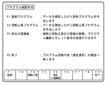
図8は、自動プログラム作成装置60によりNC加工プログラムを作成する手順を示すフローチャートである。操作者は、手順101で素材工作物の形状の入力を行う。次に、手順102で旋削加工の仕上げ形状を入力し、さらに手順103で回転工具加工の仕上げ形状を入力する。次に、手順104で工作物のインデックス位置の設定と、加工種類の設定を行う。そして、手順105でNC加工プログラムの自動作成を指示し、旋削加工と回転工具加工のNC加工プログラムを自動的に作成する。
【0052】
次に手順106で、図4の結合工程編集画面において、工程の順序の入れ換え、タレット工具番号の変更等の作業を行い、NC加工プログラムを変更して作成する。この際、図4のような画面により、工程の変更作業、タレット工具番号の変更作業等が簡単に行えるため、NC加工プログラムのコードを直接編集する必要がなく、編集作業を容易に行うことができ、また、編集ミス等も発生しにくくなる。
【0053】
そして、手順107で作成したNC加工プログラムの加工動作を画面上に動画表示することによって、NC加工プログラムのチェックを行う。加工動作に問題がなければ、手順108でNC加工プログラムをNC装置50に転送して、NC加工プログラムの作成作業を終了する。
【0054】
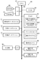
図9は、結合工程編集プログラム642の処理を示すフローチャートである。結合工程編集プログラム642は、自動プロ機能用プログラム641から呼び出され、図4の結合工程編集画面の処理を行うプログラムである。結合工程編集プログラム642が呼び出されると、まず処理201で、結合工程編集画面の表示を行う。次に、判断202でF1キーが押されているか否かを判断する。F1キーが押されていなければ判断203に進み、押されていれば処理210において現在のデータからNC加工プログラムを作成し、その後、判断202に戻る。
【0055】
判断203では、F2キーが押されているか否かを判断する。F2キーが押されていなければ判断204に進み、押されていれば処理211においてNC加工プログラムの動画チェック画面を表示し、動画チェックが終了すれば判断202に戻る。次の判断204では、F3キーが押されているか否かを判断する。F3キーが押されていなければ判断205に進み、押されていれば処理212においてNC加工プログラムの編集画面を表示し、編集が終了すれば判断202に戻る。
【0056】
判断205では、F4キーが押されているか否かを判断する。F4キーが押されていなければ判断206に進み、押されていれば処理213において操作者の指示に従って工程の入れ換え等の変更を行い、その後、判断202に戻る。次の判断206では、F5キーが押されているか否かを判断する。F5キーが押されていなければ判断207に進み、押されていれば処理214において操作者の指示に従って工程の転送移動を行い、その後、判断202に戻る。
【0057】
判断207では、F6キーが押されているか否かを判断する。F6キーが押されていなければ判断208に進み、押されていれば処理215においてタレット工具番号の変更を行い、その後、判断202に戻る。次の判断208では、F8キーが押されているか否かを判断する。F8キーが押されていなければ判断209に進み、押されていれば処理216においてサブプログラムの編集画面を表示し、編集が終了すれば判断202に戻る。最後の判断209では、F9キーが押されているか否かを判断する。F9キーが押されていなければ判断202に戻り、押されていれば結合工程編集プログラム642を終了して呼び出し元に戻る。
【0058】
以上のように、NC加工プログラム作成の際に部分工程間に連結処理A,Bが自動的に挿入されるため、自動プログラム作成装置により自動作成された部分工程の順番を、操作者が入れ換えて最適な順番とすることが容易に行える。このため、最小の工程数により加工結果を最良のものとすることができる。また、自動プログラム作成装置により自動作成されたタレット工具番号を簡単に変更できるようにしたので、工具交換回数を最小限の回数として能率よく加工を行うことができる。
【0059】
なお、以上の実施の形態においては、工作機械としてターニングセンタを例にとって説明したが、旋削工具による加工と回転工具による加工の両方が可能であればどのような工作機械にも本発明を適用できる。
【0060】
【発明の効果】
NC加工プログラム作成の際に部分工程間に連結プログラムを自動的に挿入するようにしたので、部分工程の順番を操作者が入れ換えて最適な順番とすることが容易に行える。このため、最小の工程数により加工結果を最良のものとすることができる。また、NC加工プログラムのコードを直接編集する必要がなく、工程順序の編集作業を容易に行うことができるため、編集ミス、修正もれ等も発生しにくくなる。
【0061】
連結プログラムの先頭部に順次異なるシーケンス番号を付与してNC加工プログラム内に挿入するようにしたので、部分工程の接続部分を検索する場合に便利である。特に、NC加工プログラムの加工動作を中断し、その後NC加工プログラムを途中から再開させるような場合に操作が容易になる。
【0062】
自動プログラム作成装置により自動作成されたタレット工具番号を簡単に変更できるようにしたので、工具交換回数を最小限の回数として能率よく加工を行うことができる。
【図面の簡単な説明】
【図1】図1は、本発明を適用するターニングセンタの斜視図である。
【図2】図2は、自動プログラム作成装置の構成を示すブロック図である。
【図3】図3は、プログラム確認作成の画面表示を示す図である。
【図4】図4は、結合工程編集の画面表示を示す図である。
【図5】図5は、工程の変更の一例を示す図である。
【図6】図6は、工程の変更を行った場合の、NC加工プログラムの構成の変化を示す図である。
【図7】図7は、連結処理の例を示す図である。
【図8】図8は、自動プログラム作成装置によりNC加工プログラムを作成する手順を示すフローチャートである。
【図9】図9は、結合工程編集プログラムの処理を示すフローチャートである。
【図10】図10は、工程の順序による加工結果の差異を示すための図である。
【図11】図11は、工程の順序を入れ換えた場合の加工結果を示す図である。
【符号の説明】
1…ベッド
2…Z軸案内部材
3…往復台
7…Y軸送り台
B…バリ
W…工作物
11…刃物台本体
16…タレット
17…心押台
18…主軸台
19…主軸
20…プーリ
22…プーリ
21…Vベルト
23…主軸駆動モータ
24…C軸制御ユニット
25…C軸制御モータ
26…Z軸モータ
30…自動工具交換装置
40…工具マガジン
50…NC装置
60…自動プログラム作成装置[0001]
BACKGROUND OF THE INVENTION
The present invention relates to a turning center capable of rotating a workpiece and processing it with a turning tool on a workpiece held by a chuck at the tip of a spindle, and performing processing with a rotating tool that rotates the tool itself. The present invention relates to a method and apparatus for creating an NC machining program for a machine tool.
[0002]
[Prior art]
Machine tools such as turning centers that can work with a turning tool by rotating the work on the work gripped by the chuck at the tip of the spindle and with a rotating tool that rotates the tool itself Is known. FIG. 1 is a perspective view showing an example of a turning center.
[0003]
On the upper surface of the
[0004]
A tool post body 11 is provided on the Y-
[0005]
A
[0006]
The rotational angle position of the
[0007]
According to such a turning center, the work piece is gripped by the chuck at the tip of the
[0008]
In order to perform machining by such a turning center, it is necessary to create an NC machining program. This NC machining program is difficult to create unless it is an operator who understands both NC machining programs for turning and rotary tool machining. Therefore, an automatic program creation device or automatic program creation for automatically creating NC machining programs is required. An NC (numerical control) device having a function is often used.
[0009]
Such an automatic program creation function includes an NC lathe automatic program creation function for performing turning and a machining center (hereinafter referred to as MC) automatic program creation function for performing machining with a rotating tool. In both automatic program creation functions, the input method of finishing shape data and the like is different. As for the NC machining program itself, the NC machining program for NC lathe, where the workpiece is rotated and machining is performed, and the NC machining program for MC, which is machined by rotating the tool, differ in the meaning of the NC command. .
[0010]
[Problems to be solved by the invention]
When an NC machining program is created by the automatic program creation function of the turning center as described above, a partial process of turning is first output, and then a partial process of rotating tool machining such as milling is output. However, there are cases where it is better to perform a process by rotating tool machining before a part of the process of turning. An example of the case where the process needs to be replaced will be described with reference to FIGS.
[0011]
For example, when turning the outer peripheral surface of the workpiece W and further drilling the outer peripheral surface with a drill, in the automatic program creation function, as shown in FIG. The NC machining program is created by arranging the steps in the order of diameter finishing and (c) drilling. Thus, since the drilling which is the rotary tool processing is the last step, when the machining is performed as it is by this NC machining program, the burrs B are finally formed on the outer peripheral surface of the workpiece W as shown in FIG. Will remain.
[0012]
As shown in FIG. 11, when the process is changed in the order of (a) outer diameter roughing, (b) drilling, and (c) outer diameter finishing, the burr B is formed by the final outer diameter finishing. Is removed and the desired final processing result is obtained. In such a case, the NC machining program that was automatically created was edited by the operator on the automatic program creation device or NC device side, and the machining process was changed. There is also a risk that the machine tool may perform an incorrect machining operation due to an editing mistake or a correction leak.
[0013]
Therefore, the present invention provides a machine tool that allows an operator to easily change the order of each machining step of an NC machining program that is automatically created, if necessary, in an automatic program creation function of a machine tool such as a turning center. It is an object of the present invention to provide a method and apparatus for creating an NC machining program for a machine.
[0014]
[Means for Solving the Problems]
In order to achieve the above object, an NC machining program creation method for a machine tool according to the present invention is an NC machining program for a machine tool capable of machining with a turning tool, that is, turning, and machining with a rotating tool, that is, rotating tool. A creation method, a procedure for inputting a shape of a material workpiece to be machined, a procedure for inputting a finished shape by the turning, a procedure for inputting a finished shape by the rotary tool machining, and a finishing by the turning One or more turning partial processes that are partial processes for forming a shape are created, and at least one rotary tool partial process that is a partial process for forming a finished shape by the rotary tool machining is created, and the turning A process display procedure for displaying the partial process and the rotary tool partial process; the turning partial process displayed in the process display procedure; An NC editing program is created by connecting an editing procedure that enables changing of the order of the turning tool partial process, the turning part process and the rotating tool partial process according to the order determined by the editing procedure, and the turning part For changing the machining type from the turning to the rotary tool machining in the connecting part where the rotary tool part process follows the process Consists of multiple NC commands Inserting a first connection program and changing the machining type from the rotary tool machining to the turning process in a connecting part where the turning part process follows the rotary tool partial process Consists of multiple NC commands And a program creation procedure for inserting the second linked program.
[0015]
In the NC machining program creation method of the machine tool, the program creation procedure includes: The first connection program and the second connection program It is preferable that different sequence numbers are sequentially assigned to the head of the NC machining program and inserted into the NC machining program.
[0017]
In the NC machining program creation method of the machine tool, the process display procedure displays a turret tool number for designating a tool to be used for the turning part process and the rotating tool part process, It is preferable to have a procedure that allows the turret tool number to be changed.
[0018]
In the NC machining program creation method for a machine tool, the turret tool number preferably includes a turret surface number that specifies a tool mounting portion of the turret and a tool number that specifies a tool.
[0019]
An NC machining program creation device for a machine tool of the present invention is an NC machining program creation device for a machine tool capable of machining with a turning tool, that is, turning, and machining with a rotating tool, that is, rotating tool. Display means capable of displaying characters or figures, input means for the operator to input data, material shape storage means for storing data of the shape of the material workpiece to be machined, and the finish shape by the turning Turning tool finishing shape storage means for storing data, rotating tool finishing shape storage means for storing finishing shape data by the rotary tool machining, and a turning partial process which is a partial process for forming the finishing shape by the turning process A rotary tool partial process that is a partial process for forming a finished shape by the rotary tool machining. It is possible to change the order of the turning part process and the rotating tool part process displayed by the process display means and the process display means which are created by displaying two or more of the turning part process and the rotating tool part process on the display means. The process sequence editing means, the turning partial process and the rotary tool partial process are connected according to the order determined by the process order editing means to create an NC machining program, and after the turning partial process, the rotary tool For changing the machining type from the turning to the rotary tool machining at the connection part where the partial process continues Consists of multiple NC commands Inserting a first connection program and changing the machining type from the rotary tool machining to the turning process in a connecting part where the turning part process follows the rotary tool partial process Consists of multiple NC commands It has program creation means for inserting a second linked program, and linked program storage means for storing the first linked program and the second linked program.
[0020]
In the NC machining program creation device for the machine tool, the program creation means includes: The first connection program and the second connection program It is preferable that different sequence numbers are sequentially assigned to the head of the NC machining program and inserted into the NC machining program.
[0022]
Further, in the NC machining program creation device of the machine tool, the process display means displays a turret tool number for designating a tool to be used for the turning part process and the rotating tool part process, It is preferable to have a tool editing means that can change the turret tool number.
[0023]
In the NC machining program creation device of the above machine tool, it is preferable that the turret tool number includes a turret surface number that specifies a tool mounting portion of the turret and a tool number that specifies a tool.
[0024]
DETAILED DESCRIPTION OF THE INVENTION
Embodiments of the present invention will be described with reference to the drawings. FIG. 1 is a perspective view of a turning center as a machine tool to which the present invention is applied. The description of each member and the operation of the turning center are as described above. This turning center is controlled by the NC device 50 (see FIG. 2). Further, an automatic
[0025]
FIG. 2 is a block diagram showing the configuration of the automatic
[0026]
The
[0027]
A
[0028]
Further, a
[0029]
Input / output devices are connected to the
[0030]
Further, a fixed disk device as an auxiliary storage device may be connected to the
[0031]
The cutting condition data file 71 is a data file that is provided on a memory or a fixed disk and stores a large number of cutting condition data. Similarly, the tool data file 72 is a data file which is provided on a memory or a fixed disk and stores a large number of tool data (data such as tool type and tool size).
[0032]
The process order data file 73 is a data file that is provided on a memory or a fixed disk and stores the order of a plurality of partial processes corresponding to machining with a turning tool and machining with a rotating tool. For example, in the case of machining with a rotating tool, milling roughing process, center machining process, drilling process, boring roughing process, chamfering process, tapping process, ..., boring finishing process, milling The order as in the finishing process is stored. Also, in the case of machining with a turning tool, the order of transition from the rough machining process to the finishing process is stored.
[0033]
An
[0034]
FIG. 3 is a diagram showing a screen display for creating a program confirmation displayed on the display means 69 of the automatic
[0035]
When the F3 key is pressed from the program confirmation creation screen of FIG. 3, the screen shifts to the NC machining program creation screen for rotary tool machining. On the NC machining program creation screen for rotary tool machining, the finish shape of the rotary tool machining is input and the NC machining program is automatically created. The rotary tool finishing shape data input by the operator is stored in the rotary tool finishing
[0036]
FIG. 4 is a diagram illustrating a screen display for the combination process editing. This screen is called by pressing the F5 key from the program confirmation creation screen of FIG. In the upper left part of the screen, the partial processes of the NC machining program created on the program confirmation creation screen are arranged in order and displayed as a process chart. As for the order of each partial process, the partial process of turning is arranged first, and the partial process of rotary tool processing is after. There are two types of drill tools: a drill tool as a fixed tool used for turning and a drill tool as a rotary tool used for rotary tool processing. The drill tool of
[0037]
On this combined process edit screen, the NC machining program for each partial process can be edited by moving the cursor to the desired process number in the process number column at the left end of the process table and pressing the F3 key. The process number is displayed in green in the turning process and is displayed in white in the rotary tool process. When the F4 key is pressed, the order of the processes can be changed. When the F4 key is pressed, the start number and end number of
[0038]
When the F5 key is pressed, a desired range of steps can be transferred to a desired position. When the F5 key is pressed, the start number, end number, and transfer destination number in the
[0039]
In the data of “Tmm nn” in the turret tool number column, “mm” designates the turret surface number, and “nn” designates the tool number.
[0040]
When the F6 key is pressed on the combined process edit screen, the cursor is displayed in the data section of the turret tool number column, and the cursor is moved to the data to be corrected by the cursor key and page key. Correct the data. In the NC machining program automatically created by the automatic
[0041]
When the F8 key is pressed on the combined process edit screen, the subprogram called from the process program in the cursor line can be edited. In addition, when a cursor is placed on a desired process number and an erase key (not shown) is pressed, the process can be erased. When the F1 key is pressed after the above editing operation, a new NC machining program reflecting the editing result is automatically created. At that time, different types of partial processes are required at the location where the rotary tool machining partial process is connected after the turning partial process, and at the location where the turning partial process is connected after the rotary tool machining partial process. The programs of the connection processes A and B that enable the connection are inserted.
[0042]
Further, when the F2 key is pressed on the coupling process edit screen, the machining operation of the created NC machining program is displayed as a moving image on the screen, whereby the NC machining program can be checked. When the F9 key is pressed, the joining process editing screen is terminated and the program confirmation creation screen shown in FIG. 3 is returned.
[0043]
FIG. 5 is a diagram illustrating an example of replacement of partial processes. FIG. 5A shows the order of the partial steps in the NC machining program automatically created by the automatic
[0044]
FIG. 6 is a diagram showing a change in the configuration of the NC machining program when the process is changed as shown in FIG. The NC machining program in the process sequence of FIG. 5A is shown in FIG. 6A, and the NC machining program in the process sequence of FIG. 5B is shown in FIG. 6B. Each line in FIGS. 6A and 6B shows the processing of the NC machining program for executing each partial process, and the leftmost number corresponds to the process number in FIGS. 5A and 5B. . Lines with blank numbers at the left end are other automatically created program parts that are not displayed in FIGS. 5 (a) and 5 (b).
[0045]
In order to change the machining type from turning to rotary tool machining, it is necessary to execute the program of the linkage process A. To change the machining type from rotary tool machining to turning, the program of the linkage process B is executed. There is a need. In the NC machining program of FIG. 6 (a), the connection process A is arranged between the inner threading process of
[0046]
In the combined process edit screen, when the order of processes is changed as shown in FIGS. 5A to 5B and the F1 key is pressed to instruct the creation of an NC machining program, the NC machining program is shown in FIG. 6A. 6 (b) is changed. The program of the connection process A is inserted in the place where the machining type is changed from turning to rotary tool machining (between
[0047]
FIG. 7 is a diagram illustrating an example of the connection processes A and B. FIG. 7A shows a program for the connection process A, and FIG. 7B shows a program for the connection process B. These connection processes A and B are stored as a
[0048]
“N50000” in the first line of the connection process A in FIG. 7A is a sequence number, and when the connection process A is actually inserted into the NC machining program, “N50000”, “N50001”, and so on. Each time it is inserted, it is incremented by one. “M09” is a command to stop the supply of the cutting fluid. “G80” in the second line is a command to cancel the fixed cycle, and “M05” is a command to stop the spindle rotation. “G50S3000P2” in the third line is a command for setting a limit value for the rotational speed of the rotary tool. “M01” on the fourth line is an optional stop command.
[0049]
“N51000” in the first line of the connection process B in FIG. 7B is a sequence number, and when the connection process B is actually inserted into the NC machining program, “N51000”, “N51001”, and so on. Each time it is inserted, it is incremented by one. “G18” is a command for designating the coordinate plane as the Z-X plane, “G97” is a command for canceling the constant peripheral speed control of the spindle, “G99” is a command for instructing a feed per revolution, and “M41” is a diameter correction. Command to cancel. “M01” in the second line is an optional stop command.
[0050]
The connection processes A and B are not limited to these examples, and other arbitrary NC commands can be registered. In the concatenation process A, the first sequence number is incremented by 1 sequentially from “50000”, and in the concatenation process B, the first sequence number is incremented by 1 sequentially from “51000”. This is convenient when searching for concatenation processing. For example, the operation is facilitated when the machining operation of the NC machining program is interrupted and then the NC machining program is resumed from the middle.
[0051]
FIG. 8 is a flowchart showing a procedure for creating an NC machining program by the automatic
[0052]
Next, in
[0053]
Then, the NC machining program is checked by displaying the machining operation of the NC machining program created in
[0054]
FIG. 9 is a flowchart showing the processing of the joining
[0055]
In
[0056]
In
[0057]
In
[0058]
As described above, since the connection processes A and B are automatically inserted between the partial processes when creating the NC machining program, the operator can change the order of the partial processes automatically created by the automatic program creation device. The optimal order can be easily achieved. For this reason, the processing result can be optimized with the minimum number of steps. Further, since the turret tool number automatically created by the automatic program creation device can be easily changed, machining can be efficiently performed with the minimum number of tool exchanges.
[0059]
In the above embodiment, the turning center has been described as an example of a machine tool. However, the present invention can be applied to any machine tool as long as both machining with a turning tool and machining with a rotary tool are possible. .
[0060]
【The invention's effect】
Since the connecting program is automatically inserted between the partial processes when creating the NC machining program, the operator can easily change the order of the partial processes to the optimum order. For this reason, the processing result can be optimized with the minimum number of steps. Further, it is not necessary to directly edit the NC machining program code, and the process sequence can be easily edited, so that editing errors and correction errors are less likely to occur.
[0061]
Since different sequence numbers are sequentially assigned to the head of the connection program and inserted into the NC machining program, it is convenient when searching for a connection part of a partial process. In particular, the operation is facilitated when the machining operation of the NC machining program is interrupted and then the NC machining program is resumed from the middle.
[0062]
Since the turret tool number automatically created by the automatic program creation device can be easily changed, machining can be efficiently performed with the minimum number of tool changes.
[Brief description of the drawings]
FIG. 1 is a perspective view of a turning center to which the present invention is applied.
FIG. 2 is a block diagram illustrating a configuration of an automatic program creation device.
FIG. 3 is a diagram showing a screen display for creating a program confirmation;
FIG. 4 is a diagram illustrating a screen display of a combination process editing.
FIG. 5 is a diagram illustrating an example of a process change.
FIG. 6 is a diagram showing a change in the configuration of an NC machining program when a process is changed.
FIG. 7 is a diagram illustrating an example of connection processing;
FIG. 8 is a flowchart showing a procedure for creating an NC machining program by an automatic program creation device.
FIG. 9 is a flowchart showing processing of a joining process editing program.
FIG. 10 is a diagram for illustrating a difference in processing results depending on the order of steps.
FIG. 11 is a diagram illustrating a processing result when the order of steps is changed.
[Explanation of symbols]
1 ... Bed
2 ... Z-axis guide member
3 ... round-trip
7 ... Y-axis feed base
B ... Bali
W ... Workpiece
11 ... Turret body
16 ... Turret
17 ... Tailstock
18 ... headstock
19 ... Spindle
20 ... pulley
22 ... Pulley
21 ... V belt
23 ... Spindle drive motor
24 ... C-axis control unit
25 ... C-axis control motor
26 ... Z-axis motor
30 ... Automatic tool changer
40 ... Tool magazine
50 ... NC device
60 ... Automatic program creation device
Claims (8)
加工を行う素材工作物の形状を入力する手順と、
前記旋削加工による仕上げ形状を入力する手順と、
前記回転工具加工による仕上げ形状を入力する手順と、
前記旋削加工による仕上げ形状を形成するための部分工程である旋削部分工程を1つ以上作成するとともに、前記回転工具加工による仕上げ形状を形成するための部分工程である回転工具部分工程を1つ以上作成し、前記旋削部分工程および前記回転工具部分工程を表示する工程表示手順と、
前記工程表示手順で表示した前記旋削部分工程および前記回転工具部分工程の順番の変更を可能とする編集手順と、
前記旋削部分工程および前記回転工具部分工程を前記編集手順によって決定された順番に従って連結してNC加工プログラムを作成するとともに、前記旋削部分工程の後に前記回転工具部分工程が続く接続部分に前記旋削加工から前記回転工具加工に加工種類を変更するための複数のNC指令からなる第1の連結プログラムを挿入し、前記回転工具部分工程の後に前記旋削部分工程が続く接続部分に前記回転工具加工から前記旋削加工に加工種類を変更するための複数のNC指令からなる第2の連結プログラムを挿入するプログラム作成手順とを有する工作機械のNC加工プログラム作成方法。An NC machining program creation method for a machine tool capable of machining with a turning tool, that is, turning and machining with a rotating tool, that is, rotating tool,
A procedure for entering the shape of the workpiece to be machined;
A procedure for inputting a finishing shape by the turning process;
A procedure for inputting a finishing shape by the rotary tool machining;
One or more turning partial processes, which are partial processes for forming the finished shape by the turning process, are created, and one or more rotating tool partial processes, which are partial processes for forming the finished shape by the rotating tool machining, are created. Creating and displaying the turning partial process and the rotating tool partial process;
An editing procedure that enables the change of the order of the turning part process and the rotating tool part process displayed in the process display procedure,
The turning part process and the rotating tool part process are connected in accordance with the order determined by the editing procedure to create an NC machining program, and the turning process is performed on a connecting part where the rotating tool part process follows the turning part process. To the rotary tool machining is inserted a first connection program consisting of a plurality of NC commands for changing the machining type, and from the rotary tool machining to the connecting part where the turning part process follows the rotary tool part process An NC machining program creation method for a machine tool, comprising: a program creation procedure for inserting a second connection program comprising a plurality of NC commands for changing the machining type for turning.
前記プログラム作成手順は、前記第1の連結プログラムおよび前記第2の連結プログラムの先頭部に順次異なるシーケンス番号を付与して前記NC加工プログラム内に挿入するものである工作機械のNC加工プログラム作成方法。An NC machining program creation method for a machine tool according to claim 1,
An NC machining program creation method for a machine tool, in which the program creation procedure is such that different sequence numbers are sequentially assigned to the heads of the first linkage program and the second linkage program and inserted into the NC machining program. .
前記工程表示手順は、前記旋削部分工程および前記回転工具部分工程に使用する工具を指定するためのタレット工具番号を表示するものであり、
前記タレット工具番号を変更可能とする手順を有する工作機械のNC加工プログラム作成方法。An NC machining program creation method for a machine tool according to any one of claims 1 and 2,
The process display procedure displays a turret tool number for designating a tool to be used for the turning partial process and the rotary tool partial process.
An NC machining program creation method for a machine tool, having a procedure for changing the turret tool number.
前記タレット工具番号は、タレットの工具装着部を指定するタレット面番号と工具を指定する工具番号とを含むものである工作機械のNC加工プログラム作成方法。An NC machining program creation method for a machine tool according to claim 3,
An NC machining program creation method for a machine tool, wherein the turret tool number includes a turret surface number for designating a tool mounting portion of the turret and a tool number for designating a tool.
文字または図形を表示可能な表示手段(69)と、
操作者がデータを入力するための入力手段(70)と、
加工を行う素材工作物の形状のデータを記憶する素材形状記憶手段(66)と、
前記旋削加工による仕上げ形状のデータを記憶する旋削工具仕上形状記憶手段(67)と、
前記回転工具加工による仕上げ形状のデータを記憶する回転工具仕上形状記憶手段(68)と、
前記旋削加工による仕上げ形状を形成するための部分工程である旋削部分工程を1つ以上作成するとともに、前記回転工具加工による仕上げ形状を形成するための部分工程である回転工具部分工程を1つ以上作成し、前記旋削部分工程および前記回転工具部分工程を前記表示手段(69)に表示する工程表示手段(642)と、
前記工程表示手段(642)により表示した前記旋削部分工程および前記回転工具部分工程の順番の変更を可能とする工程順序編集手段(642)と、
前記旋削部分工程および前記回転工具部分工程を前記工程順序編集手段(642)によって決定された順番に従って連結してNC加工プログラムを作成するとともに、前記旋削部分工程の後に前記回転工具部分工程が続く接続部分に前記旋削加工から前記回転工具加工に加工種類を変更するための複数のNC指令からなる第1の連結プログラムを挿入し、前記回転工具部分工程の後に前記旋削部分工程が続く接続部分に前記回転工具加工から前記旋削加工に加工種類を変更するための複数のNC指令からなる第2の連結プログラムを挿入するプログラム作成手段(642)と、
前記第1の連結プログラムおよび前記第2の連結プログラムを記憶する連結プログラム記憶手段(65)とを有する工作機械のNC加工プログラム作成装置。An NC machining program creation device for a machine tool capable of machining with a turning tool, that is, turning, and machining with a rotating tool, that is, rotating tool,
Display means (69) capable of displaying characters or figures;
An input means (70) for an operator to input data;
Material shape storage means (66) for storing data of the shape of the material workpiece to be processed;
Turning tool finishing shape storage means (67) for storing finishing shape data by the turning,
Rotary tool finish shape storage means (68) for storing data of the finished shape by the rotary tool processing;
One or more turning partial processes, which are partial processes for forming the finished shape by the turning process, are created, and one or more rotating tool partial processes, which are partial processes for forming the finished shape by the rotating tool machining, are created. Creating and displaying the turning partial process and the rotating tool partial process on the display means (69);
A process sequence editing means (642) that enables changing the order of the turning part process and the rotary tool part process displayed by the process display means (642);
The turning part process and the rotating tool part process are connected in accordance with the order determined by the process order editing means (642) to create an NC machining program, and the turning part process is followed by the rotating tool part process. A first connection program comprising a plurality of NC commands for changing the machining type from the turning to the rotary tool machining is inserted into the part, and the connecting part in which the turning part process follows the rotary tool part process is inserted into the connection part. A program creation means (642) for inserting a second connection program comprising a plurality of NC commands for changing the machining type from the rotary tool machining to the turning machining;
An NC machining program creation device for a machine tool, comprising connection program storage means (65) for storing the first connection program and the second connection program.
前記プログラム作成手段(642)は、前記第1の連結プログラムおよび前記第2の連結プログラムの先頭部に順次異なるシーケンス番号を付与して前記NC加工プログラム内に挿入するものである工作機械のNC加工プログラム作成装置。An NC machining program creation device for a machine tool according to claim 5,
The program creation means (642) assigns different sequence numbers to the heads of the first connection program and the second connection program and inserts them into the NC machining program. Program creation device.
前記工程表示手段(642)は、前記旋削部分工程および前記回転工具部分工程に使用する工具を指定するためのタレット工具番号を表示するものであり、
前記タレット工具番号を変更可能とする工具編集手段(642)を有する工作機械のNC加工プログラム作成装置。An NC machining program creation device for a machine tool according to any one of claims 5 and 6,
The process display means (642) displays a turret tool number for designating a tool used for the turning part process and the rotating tool part process,
An NC machining program creation device for a machine tool, having tool editing means (642) that allows the turret tool number to be changed.
前記タレット工具番号は、タレットの工具装着部を指定するタレット面番号と工具を指定する工具番号とを含むものである工作機械のNC加工プログラム作成装置。An NC machining program creation device for a machine tool according to claim 7,
The machine tool NC machining program creation device, wherein the turret tool number includes a turret surface number designating a tool mounting portion of the turret and a tool number designating a tool.
Priority Applications (1)
| Application Number | Priority Date | Filing Date | Title |
|---|---|---|---|
| JP33818298A JP4286940B2 (en) | 1998-11-27 | 1998-11-27 | NC machining program creation method and apparatus for machine tools |
Applications Claiming Priority (1)
| Application Number | Priority Date | Filing Date | Title |
|---|---|---|---|
| JP33818298A JP4286940B2 (en) | 1998-11-27 | 1998-11-27 | NC machining program creation method and apparatus for machine tools |
Publications (2)
| Publication Number | Publication Date |
|---|---|
| JP2000158290A JP2000158290A (en) | 2000-06-13 |
| JP4286940B2 true JP4286940B2 (en) | 2009-07-01 |
Family
ID=18315706
Family Applications (1)
| Application Number | Title | Priority Date | Filing Date |
|---|---|---|---|
| JP33818298A Expired - Fee Related JP4286940B2 (en) | 1998-11-27 | 1998-11-27 | NC machining program creation method and apparatus for machine tools |
Country Status (1)
| Country | Link |
|---|---|
| JP (1) | JP4286940B2 (en) |
Families Citing this family (3)
| Publication number | Priority date | Publication date | Assignee | Title |
|---|---|---|---|---|
| JP3995558B2 (en) * | 2002-08-20 | 2007-10-24 | シチズンホールディングス株式会社 | Control method and control device for tool selection operation of turret tool post |
| JP5418108B2 (en) * | 2009-09-24 | 2014-02-19 | 村田機械株式会社 | NC program editing device and processing machine control device |
| WO2014168152A1 (en) * | 2013-04-11 | 2014-10-16 | シチズンホールディングス株式会社 | Offset number setting device |
-
1998
- 1998-11-27 JP JP33818298A patent/JP4286940B2/en not_active Expired - Fee Related
Also Published As
| Publication number | Publication date |
|---|---|
| JP2000158290A (en) | 2000-06-13 |
Similar Documents
| Publication | Publication Date | Title |
|---|---|---|
| US4547854A (en) | Method of controlling lineup of tools in numerical control machine tool | |
| KR940007132B1 (en) | Automatic programming system | |
| US4739488A (en) | Machine tool with tool selection and work sequence determination | |
| US4604705A (en) | Numerical control machining method and system therefor | |
| JP4011372B2 (en) | Machining program check method and check apparatus for numerically controlled machine tool, and numerically controlled machine tool provided with the same | |
| JPH0375887B2 (en) | ||
| EP0223857B1 (en) | Method of compiling nc programs for a four-axes lathe | |
| JPH0248378B2 (en) | ||
| JPH028855B2 (en) | ||
| JP3517403B2 (en) | Multi-task machine tools | |
| JP4580142B2 (en) | Numerical control lathe, control device used in numerical control lathe, control method of numerical control lathe, and machining program description method of control device in numerical control lathe | |
| WO2004011193A1 (en) | Tool selection method for machine tool, control devcie, and numerically controlled lathe | |
| JP2001328002A (en) | Machine tool | |
| US5058029A (en) | Setting control method of machining coordinate system in a machine tool | |
| JP4059411B2 (en) | NC machine tool controller | |
| JP4286940B2 (en) | NC machining program creation method and apparatus for machine tools | |
| JP2002079401A (en) | Composite working machine tool | |
| TW201924847A (en) | Automatic tool changing system and method | |
| JPH05305540A (en) | Tool exchange method for working device | |
| KR20020000527A (en) | Complex machining machine tool | |
| JPH0623640A (en) | Method and device for exchanging tool for numerically controlled machine tool | |
| WO2022113223A1 (en) | Machine tool | |
| JPH06155103A (en) | Machining controlling method for two opposed spindle lathe | |
| JPH01205954A (en) | Automatic determination device for tool route of machine tool | |
| JP2764012B2 (en) | Grinding equipment |
Legal Events
| Date | Code | Title | Description |
|---|---|---|---|
| A625 | Written request for application examination (by other person) |
Free format text: JAPANESE INTERMEDIATE CODE: A625 Effective date: 20051024 |
|
| A977 | Report on retrieval |
Free format text: JAPANESE INTERMEDIATE CODE: A971007 Effective date: 20070628 |
|
| A131 | Notification of reasons for refusal |
Free format text: JAPANESE INTERMEDIATE CODE: A131 Effective date: 20070629 |
|
| A521 | Written amendment |
Free format text: JAPANESE INTERMEDIATE CODE: A523 Effective date: 20070821 |
|
| A02 | Decision of refusal |
Free format text: JAPANESE INTERMEDIATE CODE: A02 Effective date: 20071115 |
|
| A521 | Written amendment |
Free format text: JAPANESE INTERMEDIATE CODE: A523 Effective date: 20080111 |
|
| A911 | Transfer of reconsideration by examiner before appeal (zenchi) |
Free format text: JAPANESE INTERMEDIATE CODE: A911 Effective date: 20080124 |
|
| A912 | Removal of reconsideration by examiner before appeal (zenchi) |
Free format text: JAPANESE INTERMEDIATE CODE: A912 Effective date: 20080215 |
|
| A01 | Written decision to grant a patent or to grant a registration (utility model) |
Free format text: JAPANESE INTERMEDIATE CODE: A01 |
|
| A61 | First payment of annual fees (during grant procedure) |
Free format text: JAPANESE INTERMEDIATE CODE: A61 Effective date: 20090326 |
|
| FPAY | Renewal fee payment (event date is renewal date of database) |
Free format text: PAYMENT UNTIL: 20120403 Year of fee payment: 3 |
|
| R150 | Certificate of patent or registration of utility model |
Free format text: JAPANESE INTERMEDIATE CODE: R150 |
|
| FPAY | Renewal fee payment (event date is renewal date of database) |
Free format text: PAYMENT UNTIL: 20150403 Year of fee payment: 6 |
|
| R250 | Receipt of annual fees |
Free format text: JAPANESE INTERMEDIATE CODE: R250 |
|
| LAPS | Cancellation because of no payment of annual fees |