JP4286637B2 - Microphone device and playback device - Google Patents
Microphone device and playback device Download PDFInfo
- Publication number
- JP4286637B2 JP4286637B2 JP2003385375A JP2003385375A JP4286637B2 JP 4286637 B2 JP4286637 B2 JP 4286637B2 JP 2003385375 A JP2003385375 A JP 2003385375A JP 2003385375 A JP2003385375 A JP 2003385375A JP 4286637 B2 JP4286637 B2 JP 4286637B2
- Authority
- JP
- Japan
- Prior art keywords
- signal
- unit
- microphone
- target sound
- noise
- Prior art date
- Legal status (The legal status is an assumption and is not a legal conclusion. Google has not performed a legal analysis and makes no representation as to the accuracy of the status listed.)
- Expired - Fee Related
Links
Images


Landscapes
- Circuit For Audible Band Transducer (AREA)
Abstract
Description
本発明は、マイクロホン装置および音声再生装置に関し、より特定的には、所定の方向から到来する音を雑音を抑圧して検出するマイクロホン装置および音声再生装置である。 The present invention relates to a microphone device and a sound reproduction device, and more specifically, a microphone device and a sound reproduction device that detect noise coming from a predetermined direction while suppressing noise.
従来のマイクロホン装置の構成について図24から図26を用いて説明する。
図24は、従来例1のマイクロホン装置の構成を示す図である。図24において、マイクロホン装置は、第1のマイクロホンユニット1010と、第2のマイクロホンユニット1020と、信号加算部1030と、第1の信号減算部1031と、信号増幅部1050と、適応フィルタ部1060と、第2の信号減算部1062とを備えている。各マイクロホンユニット1010および1020は、ともに正面方向(図24では左方向)を向くように配置される。信号加算部1030は、第1のマイクロホンユニット1010から出力される信号と第2のマイクロホンユニット1020から出力される信号とを加算する。第1の信号減算部1031は、第1のマイクロホンユニット1010から出力される信号から、第2のマイクロホンユニット1020から出力される信号を減算する。信号増幅部1050は、信号加算部1030から出力される信号を1/2倍する。適応フィルタ部1060は、第1の信号減算部1031から出力される信号を入力とし、適応フィルタによってフィルタリングを行った信号を出力する。第2の信号減算部1062は、信号増幅部1050から出力される信号から、適応フィルタ部1060から出力される信号を減算する。第2の信号減算部1062からの出力が、マイクロホン装置の出力となる。適応フィルタ部1060は、第2の信号減算部1062から出力される信号と第1の信号減算部1031から出力される信号とに基づいて、フィルタ係数の学習を行う。
A configuration of a conventional microphone device will be described with reference to FIGS.
FIG. 24 is a diagram showing a configuration of the microphone device of the first conventional example. In FIG. 24, the microphone device includes a
次に、従来例1のマイクロホン装置の動作について説明する。正面方向から到来する音を検出する場合、各マイクロホンユニット1010および1020はほぼ等しい信号を出力する。また、正面方向以外の方向から到来する音を検出する場合、各マイクロホンユニット1010および1020は位相の異なる信号を出力する。各マイクロホンユニット1010および1020からの出力信号は信号加算部1030によって加算される。加算された信号は、信号増幅部1050によってレベルが正規化される、すなわち、振幅が1/2倍される。以上によって、正面方向から到来する音の成分を有する主信号を得ることができる。一方、第1の信号減算部1031からの出力によって、正面方向に対して指向性主軸が90度方向に向き、かつ、正面方向が指向性の死角となる(すなわち、正面方向が指向性の最小感度方向となる)ような指向性特性を得ることができる。つまり、第1の信号減算部1031から出力される信号は、正面方向から到来する音の成分を含まない雑音参照信号となる。適応フィルタ部1060は、信号増幅部1050から出力される主信号と第1の信号減算部1031から出力される雑音参照信号とを用いることによって、適応指向性を実現する。すなわち、正面方向以外から到来するある一方向の雑音源に対して自動的に指向性の死角を形成する。
Next, the operation of the microphone device of Conventional Example 1 will be described. When detecting sound coming from the front direction, the
図25は、従来例2のマイクロホン装置の構成を示す図である。図25において、マイクロホン装置は、第1のマイクロホンユニット1010と、第2のマイクロホンユニット1020と、第1の適応フィルタ部1040と、第1の信号遅延部1041と、第1の信号減算部1042と、第2の適応フィルタ部1060と、第2の信号遅延部1061と、第2の信号減算部1062とを備えている。
FIG. 25 is a diagram showing a configuration of a microphone device of Conventional Example 2. In FIG. 25, the microphone device includes a
第1の適応フィルタ部1040は、第2のマイクロホンユニット1020からの出力信号を入力として適応フィルタによるフィルタリング結果を出力する。第1の信号遅延部1041は、第1のマイクロホンユニット1010から出力される信号を遅延させる。第1の信号減算部1042は、第1の信号遅延部1041から出力される信号から、第1の適応フィルタ部1040から出力される信号を減算する。第1の適応フィルタ部1040は、第1の信号減算部1042から出力される信号と、第2のマイクロホンユニット1020から出力される信号とに基づいて、フィルタ係数の学習を行う。第2の信号遅延部1061は、第1の信号遅延部1041から出力される信号に対して遅延を与える。第2の適応フィルタ部1060は、第1の信号減算部1042から出力される信号を入力として適応フィルタによるフィルタリング結果を出力する。第2の信号減算部1062は、第2の信号遅延部1061から出力される信号から、第2の適応フィルタ部から出力される信号を減算してマイクロホン装置の出力とする。第2の適応フィルタ部1060は、第2の信号減算部1062から出力される信号と、第1の信号減算部から出力される信号とに基づいて、フィルタ係数の学習を行う。
The first
以下、従来例2のマイクロホン装置の動作を説明する。従来例2における第1の適応フィルタ部1040、第1の信号遅延部1041、および第1の信号減算部1042は、各マイクロホンユニット1010および1020に到来した音波に対してキャンセル動作を行うものである。すなわち、第1の信号減算部1042から出力される信号は、第2の適応フィルタ部1060に対する雑音参照信号となる。また、第1の信号減算部1042から出力される信号は、図24に示す第1の信号減算部1031から出力される信号と同様の目的の信号である。ただし、従来例1が固定指向性であるのに対して、従来例2では適応フィルタを用いることによって指向性を変化させることができる点で異なっている。
The operation of the microphone device of Conventional Example 2 will be described below. The first
図26は、従来例3のマイクロホン装置の構成を示す図である。図26に示すマイクロホン装置は、第1の単一指向性マイクロホンユニット1011と、第2の単一指向性マイクロホンユニット1012と、第1のFFT部1070と、第2のFFT部1080と、2入力型スペクトルサブトラクション部1090と、音声認識部2000とを備えている。
FIG. 26 is a diagram showing a configuration of a microphone device of Conventional Example 3. 26 includes a first
図26において、第1の単一指向性マイクロホンユニット1011は、指向性主軸が正面方向を向くように配置される。第2の単一指向性マイクロホンユニット1012は、指向性主軸が背面方向を向くように配置される。第1のFFT部1070は、第1の単一指向性マイクロホンユニット1011から出力される信号を入力として周波数スペクトルを求める。第2のFFT部1080は、第2の単一指向性マイクロホンユニット1012から出力される信号を入力として周波数スペクトルを求める。2入力型スペクトルサブトラクション部1090は、各FFT部1070および1080から出力される信号を入力として、第1のFFT部1070によって導出される信号スペクトルから、第2のFFT部1080によって導出される信号スペクトルをパワスペクトル領域で減算することによって、目的信号のスペクトルを出力する。音声認識部2000は、2入力型スペクトルサブトラクション部1090から出力される目的信号のスペクトルを入力として音声認識を行う。
In FIG. 26, the first
以下、従来例3のマイクロホン装置について動作を説明する。従来例3において、第1の単一指向性マイクロホンユニット1011は、正面方向の目的音を収音する指向特性を有する。また、第2の単一指向性マイクロホンユニット1012は、主として雑音を収音する指向特性を有する。この結果、第1の単一指向性マイクロホンユニット1011から主信号m1が得られ、第2の単一指向性マイクロホンユニット1012から雑音参照信号m2が得られる。各FFT部1070および1080においては、主信号m1および雑音参照信号m2のスペクトルが求められる。2入力型スペクトルサブトラクション部1090においては、主信号のパワスペクトルから雑音参照信号のパワスペクトルが減算されることによって、信号成分のパワスペクトルが推定される。なお、1入力型のスペクトルサブトラクション法では、目的音が到来していない時間区間に雑音が定常であることを仮定して雑音スペクトルを推定している。従って、1入力型のスペクトルサブトラクション法では、定常雑音の抑圧のみを行うことができる。これに対して、2入力型のスペクトルサブトラクション法を採用する従来例3の構成によれば、第2の単一指向性マイクロホンユニット1012によって雑音参照信号のスペクトルを常に得ることができるので、非定常な雑音の抑圧を行うことが可能になる。以上のように、従来例3のマイクロホン装置によれば、定常な雑音だけでなく非定常な雑音をも抑圧することによって、後段の音声認識部2000の音声認識率を改善することができる。なお、図26に示す装置は音声認識を用途としている。ここで、最終段でIFFTを行うことによってスペクトルを時間信号に戻し、フレームオーバーラップをさせながら波形信号にすることによって、マイクロホン装置とすることも可能である。
上記の従来例1の構成では、ある一方向から騒音が到来する環境下においては大きな雑音抑圧効果を得ることができる。しかし、従来例1の装置は、複数の方向から到来する騒音には対応することができない。従って、様々な方向に騒音源が同時に存在する実際の騒音環境下においては、従来例1の構成では、従来から用いられている単一指向性のマイクロホン装置の性能と同等の雑音抑圧効果しか得ることができない。 In the configuration of the conventional example 1 described above, a large noise suppression effect can be obtained in an environment where noise comes from one direction. However, the device of Conventional Example 1 cannot cope with noise coming from a plurality of directions. Therefore, in an actual noise environment in which noise sources are simultaneously present in various directions, the configuration of the conventional example 1 obtains only a noise suppression effect equivalent to the performance of a conventionally used unidirectional microphone device. I can't.
また、従来例2の構成では、第1の適応フィルタを用いることによって雑音参照信号を得ている。ここで、実環境において第1の適応フィルタを安定に動作させるためには、話者からの音声が周囲の騒音より十分に大きなときにのみ第1の適応フィルタを学習させる必要がある。従って、従来例2の構成では、フィルタの収束が完了するまで騒音抑圧効果を得ることができない。また、騒音環境下ではフィルタの収束が困難となる。さらに、従来例1と同様、従来例2の構成では、複数の騒音源に対応することができない。また、従来例2の装置は、ユニット信号の間に相関性のない風雑音を抑圧する目的で発明されているので、目的音の方向を限定することができない。すなわち、到来する音の内、最も大きな音が目的音となってしまい、特定の方向の音を強調して収音することができない。 In the configuration of Conventional Example 2, the noise reference signal is obtained by using the first adaptive filter. Here, in order to stably operate the first adaptive filter in the actual environment, it is necessary to learn the first adaptive filter only when the voice from the speaker is sufficiently louder than the surrounding noise. Therefore, with the configuration of Conventional Example 2, the noise suppression effect cannot be obtained until the convergence of the filter is completed. In addition, it is difficult to converge the filter in a noisy environment. Further, like the conventional example 1, the configuration of the conventional example 2 cannot cope with a plurality of noise sources. Further, since the device of the conventional example 2 is invented for the purpose of suppressing wind noise having no correlation between unit signals, the direction of the target sound cannot be limited. That is, the loudest sound among the arriving sounds becomes the target sound, and the sound in a specific direction cannot be emphasized and collected.
また、従来例3の構成は、主信号と雑音参照信号とをスペクトルに変換し、パワスペクトルにおいてスペクトル減算法を用いて雑音を抑圧する方式である。この方法は、複数方向の雑音源が存在する場合でも同時に雑音を抑圧することが可能な方法である。しかし、この方法は、雑音参照信号の方に目的音が微小に混入しただけでも、処理後の音声に音質面で大きな問題が発生したり、目的音自体が打ち消されたりするという課題がある。また、実際の音場では、単一指向性マイクロホンユニットの指向性死角を目的音方向に向けても、反射波が回り込んで混入することが考えられる。さらに、通常のマイクロホンユニットは、指向性の死角が無限大の減衰量ではなく、10〜15db程度の減衰量であるので、目的音の直接波が除去しきれずに雑音参照信号に混入するおそれがある。また、スペクトル減算法の場合、フレーム処理による処理遅延が発生するので、同時通話や拡声等の用途には利用できないという課題があった。 The configuration of Conventional Example 3 is a system that converts a main signal and a noise reference signal into a spectrum and suppresses noise using a spectrum subtraction method in a power spectrum. This method is a method capable of simultaneously suppressing noise even when there are noise sources in a plurality of directions. However, this method has a problem that even if the target sound is mixed into the noise reference signal, a large problem occurs in the sound quality of the processed sound, or the target sound itself is canceled. Further, in an actual sound field, it is conceivable that reflected waves wrap around and enter even when the directional blind spot of the unidirectional microphone unit is directed to the target sound direction. Furthermore, since a normal microphone unit is not an infinite attenuation of directivity but an attenuation of about 10 to 15 db, the direct wave of the target sound may not be completely removed and may be mixed into the noise reference signal. is there. In addition, in the case of the spectrum subtraction method, a processing delay due to frame processing occurs, so that there is a problem that it cannot be used for applications such as simultaneous calls and loudspeakers.
また、上記の従来例は、目的音とは別の騒音である加法性雑音の抑圧に主眼を置いている。上記の従来例では、目的音が壁、机や床などの反射面に反射してから到達する乗法性雑音を除去することができない。従って、マイクロホン装置を実際に使用する音場における反射等の影響によって、目的音の周波数特性が歪んでしまうおそれがあった。そのため、特に音声認識などの用途では、認識時のマッチングに不整合を発生するという誤認識の問題を解決することができなかった。 Further, the above-described conventional example focuses on suppressing additive noise, which is noise different from the target sound. In the conventional example described above, multiplicative noise that arrives after the target sound is reflected on a reflecting surface such as a wall, desk, or floor cannot be removed. Therefore, the frequency characteristics of the target sound may be distorted due to the influence of reflection or the like in the sound field where the microphone device is actually used. For this reason, particularly in applications such as speech recognition, it has not been possible to solve the problem of misrecognition that causes inconsistency in matching during recognition.
それ故、本発明の目的は、実使用環境の複数の騒音下でも安定に動作するとともに、高S/Nを実現することができるマイクロホン装置を提供することである。 SUMMARY OF THE INVENTION Therefore, an object of the present invention is to provide a microphone device that can stably operate even under a plurality of noises in an actual use environment and can realize a high S / N.
また、本発明の他の目的は、目的音の反射波等に起因する乗法性雑音と、騒音に起因する加法性雑音をともに抑圧するマイクロホン装置を提供することである。 Another object of the present invention is to provide a microphone device that suppresses both multiplicative noise caused by reflected waves of the target sound and additive noise caused by noise.
また、本発明の他の目的は、雑音を抑圧する処理において用いられる主信号および雑音参照信号を簡易な方法で生成することである。 Another object of the present invention is to generate a main signal and a noise reference signal used in a process for suppressing noise by a simple method.
上記の目的を達成するために、本発明は以下の構成を採用した。すなわち、第1の発明は、目的音方向から到来する目的音を検出するマイクロホン装置である。マイクロホン装置は、信号生成部と、判定部と、適応フィルタ部と、減算部と、雑音抑圧部とを備えている。信号生成部は、目的音方向に対して感度を有して検出した結果を示す主信号と、目的音方向に対して感度死角を向けて検出した結果を示す雑音参照信号とを生成する。判定部は、信号生成部によって生成された雑音参照信号の信号レベルに対する主信号の信号レベルの割合を示すレベル比が所定の値よりも大きいか否かを判定する。適応フィルタ部は、信号生成部によって生成された主信号を適応フィルタでフィルタリングすることによって、信号生成部によって生成された雑音参照信号に含まれる目的音の信号成分を示す信号を生成するとともに、判定部によってレベル比が所定の値よりも大きいと判定された場合のみ、フィルタ係数の学習を行う。減算部は、雑音参照信号から、適応フィルタ部によって生成された、雑音参照信号に含まれる目的音の信号成分を示す信号を減算する。雑音抑圧部は、主信号と、減算部による減算後の雑音参照信号とを用いて、主信号に含まれる雑音の信号成分を抑圧する。この雑音抑圧部は、雑音抑圧フィルタ係数算出部と、時変係数フィルタ部とを含んでいる。雑音抑圧フィルタ係数算出部は、主信号と減算部による減算後の雑音参照信号とに基づいて、主信号から目的音の信号以外の信号成分を抑圧するための雑音抑圧フィルタのフィルタ係数を算出する。時変係数フィルタ部は、雑音抑圧フィルタ係数算出部によって算出されたフィルタ係数を反映して、主信号に対してフィルタリングを行う。 In order to achieve the above object, the present invention employs the following configuration. That is, the first invention is a microphone device that detects a target sound coming from a target sound direction. The microphone device includes a signal generation unit, a determination unit, an adaptive filter unit, a subtraction unit, and a noise suppression unit. The signal generation unit generates a main signal indicating a result detected with sensitivity to the target sound direction , and a noise reference signal indicating a result detected with the sensitivity blind spot directed toward the target sound direction. The determination unit determines whether or not a level ratio indicating a ratio of the signal level of the main signal to the signal level of the noise reference signal generated by the signal generation unit is greater than a predetermined value. The adaptive filter unit generates a signal indicating the signal component of the target sound included in the noise reference signal generated by the signal generation unit by filtering the main signal generated by the signal generation unit with an adaptive filter, and determines Only when it is determined by the unit that the level ratio is larger than a predetermined value, the filter coefficient is learned. Subtraction unit, the noise reference signal, generated by the adaptive filter subtracts the signal indicating the signal components of the target sound included in the noise reference signal. The noise suppression unit suppresses a signal component of noise included in the main signal using the main signal and the noise reference signal after subtraction by the subtraction unit. The noise suppression unit includes a noise suppression filter coefficient calculation unit and a time-varying coefficient filter unit. The noise suppression filter coefficient calculation unit calculates a filter coefficient of a noise suppression filter for suppressing signal components other than the target sound signal from the main signal based on the main signal and the noise reference signal after subtraction by the subtraction unit. . The time-varying coefficient filter unit performs filtering on the main signal, reflecting the filter coefficient calculated by the noise suppression filter coefficient calculation unit.
なお、「目的音方向に対して感度を有して検出した結果を示す主信号」とは、マイクロホンユニットから出力された信号そのもののみならず、マイクロホンユニットによって検出された信号に所定の加工を加えた結果得られる信号をも含む意味である。つまり、上記主信号は、目的音方向に指向性主軸が向けられたマイクロホンユニットから出力された信号そのものであってもよいし、マイクロホンユニット(無指向性であってもよいし、所定の方向に指向性主軸が向けられていてもよい)から出力された信号を加工することによって得られた信号であってもよい。これと同様に、「他の方向から到来する音を目的音よりも高い感度で検出した結果を示す雑音参照信号」とは、マイクロホンユニットから出力された信号そのものであってもよいし、マイクロホンユニットから出力された信号を加工することによって得られた信号であってもよい。 The “main signal indicating the result of detection with sensitivity to the target sound direction” is not only the signal itself output from the microphone unit, but also a predetermined process applied to the signal detected by the microphone unit. This also includes the signal obtained as a result. That is, the main signal may be a signal itself output from a microphone unit having a directional main axis directed to the target sound direction, or may be a microphone unit (which may be omnidirectional or in a predetermined direction). It may be a signal obtained by processing a signal output from a directivity main axis may be directed. Similarly, the “noise reference signal indicating the result of detecting the sound coming from other directions with higher sensitivity than the target sound” may be the signal itself output from the microphone unit or the microphone unit. It may be a signal obtained by processing the signal output from.
第2の発明は、目的音方向から到来する目的音を検出するマイクロホン装置である。マイクロホン装置は、信号生成部と、判定部と、適応フィルタ部と、減算部と、反射情報算出部と、反射補正部とを備えている。信号生成部は、目的音方向に対して感度を有して検出した結果を示す主信号と、目的音方向に対して感度死角を向けて検出した結果を示す雑音参照信号とを生成する。判定部は、信号生成部によって生成された雑音参照信号の信号レベルに対する主信号の信号レベルの割合を示すレベル比が所定の値よりも大きいか否かを判定する。適応フィルタ部は、信号生成部によって生成された主信号を適応フィルタでフィルタリングすることによって、信号生成部によって生成された雑音参照信号に含まれる目的音の信号成分を示す信号を生成するとともに、判定部によってレベル比が所定の値よりも大きいと判定された場合のみ、フィルタ係数の学習を行う。減算部は、雑音参照信号から、適応フィルタ部によって生成された、雑音参照信号に含まれる目的音の信号成分を示す信号を減算する。反射情報算出部は、適応フィルタ部のフィルタ係数に基づいて、目的音の直接波と反射波との到達時間差に関する情報を算出する。反射補正部は、反射情報算出部によって算出された情報に基づいて、目的音の反射波によって主信号に生じる周波数特性の歪を補正する。 The second invention is a microphone device for detecting a target sound coming from a target sound direction. The microphone device includes a signal generation unit, a determination unit, an adaptive filter unit, a subtraction unit, a reflection information calculation unit, and a reflection correction unit. The signal generation unit generates a main signal indicating a result detected with sensitivity to the target sound direction , and a noise reference signal indicating a result detected with the sensitivity blind spot directed toward the target sound direction. The determination unit determines whether or not a level ratio indicating a ratio of the signal level of the main signal to the signal level of the noise reference signal generated by the signal generation unit is greater than a predetermined value. The adaptive filter unit generates a signal indicating the signal component of the target sound included in the noise reference signal generated by the signal generation unit by filtering the main signal generated by the signal generation unit with an adaptive filter, and determines Only when it is determined by the unit that the level ratio is larger than a predetermined value, the filter coefficient is learned. Subtraction unit, the noise reference signal, generated by the adaptive filter subtracts the signal indicating the signal components of the target sound included in the noise reference signal. The reflection information calculation unit calculates information related to the arrival time difference between the direct wave and the reflected wave of the target sound based on the filter coefficient of the adaptive filter unit. The reflection correction unit corrects the distortion of the frequency characteristics generated in the main signal due to the reflected wave of the target sound based on the information calculated by the reflection information calculation unit.
また、第3の発明では、信号生成部は、第1のマイクロホンユニットと、第2のマイクロホンユニットとを含んでいる。第1のマイクロホンユニットは、指向性主軸が目的音方向に向けられて配置される。第2のマイクロホンユニットは、指向性の死角方向が目的音方向に向けられて配置される。第1のマイクロホンユニットからの出力信号を主信号、第2のマイクロホンユニットからの出力信号を雑音参照信号とする。 In the third invention, the signal generation unit includes a first microphone unit and a second microphone unit. The first microphone unit is arranged with the directional main axis directed in the target sound direction. The second microphone unit is arranged with the directional blind spot direction directed to the target sound direction. The output signal from the first microphone unit is the main signal, and the output signal from the second microphone unit is the noise reference signal.
また、第4の発明では、マイクロホン装置は、信号遅延部をさらに備える。信号遅延部は、信号生成部における雑音参照信号の出力端と減算部との間に設けられ、適応フィルタ部の適応フィルタの収束条件を満たすように当該雑音参照信号を遅延させる。 In the fourth invention, the microphone device further includes a signal delay unit. The signal delay unit is provided between the output end of the noise reference signal in the signal generation unit and the subtraction unit, and delays the noise reference signal so as to satisfy the convergence condition of the adaptive filter of the adaptive filter unit.
また、第5の発明では、所定の値は変更可能である。 In the fifth invention, the predetermined value can be changed.
また、第6の発明では、信号生成部は、第1のマイクロホンユニットと、第2のマイクロホンユニットと、遅延部と、増幅部と、第1の減算部と、第2の減算部とを含む。第2のマイクロホンユニットは、第1のマイクロホンユニットと同一の特性を有する。遅延部は、第1のマイクロホンユニットから出力される信号を所定の遅延量だけ遅延させて出力する。増幅部は、遅延部から出力された信号を増幅する。第1の減算部は、第2のマイクロホンユニットから出力される信号から、増幅部によって増幅された信号を減算することによって、主信号を生成する。第2の減算部は、第2のマイクロホンユニットから出力される信号から、遅延部から出力された信号を減算することによって、雑音参照信号を生成する。また、所定の遅延量は、第2の減算部から出力される雑音参照信号が持つ指向特性の死角方向が目的音方向に向くように設定される。増幅部における増幅率は、雑音参照信号より主信号のほうが目的音方向の感度が高くなるように設定される。 In the sixth invention, the signal generation unit includes a first microphone unit, a second microphone unit, a delay unit, an amplification unit, a first subtraction unit, and a second subtraction unit. . The second microphone unit has the same characteristics as the first microphone unit. The delay unit delays and outputs the signal output from the first microphone unit by a predetermined delay amount. The amplification unit amplifies the signal output from the delay unit. The first subtracting unit generates a main signal by subtracting the signal amplified by the amplifying unit from the signal output from the second microphone unit. The second subtracting unit generates a noise reference signal by subtracting the signal output from the delay unit from the signal output from the second microphone unit. The delay amount of Jo Tokoro is dead angle directivity characteristic noise reference signal output from the second subtracting unit has is set to face the target sound direction. The amplification factor in the amplification unit is set so that the main signal has higher sensitivity in the target sound direction than the noise reference signal .
また、第7の発明では、マイクロホン装置は、遅延部において設定される所定の遅延量を変化させる設定部をさらに備えている。 In the seventh invention, the microphone device further includes a setting unit that changes a predetermined delay amount set in the delay unit.
また、第8の発明では、信号生成部は、第1のマイクロホンユニットと、第2のマイクロホンユニットと、合成部とを含んでいる。第2のマイクロホンユニットは、第1のマイクロホンユニットと同一の特性を有する。合成部は、第1および第2のマイクロホンユニットから出力される各信号に基づいて、目的音方向に対して感度を有するように主信号を生成するとともに、目的音方向の感度が最小となるように雑音の信号成分を生成する。 In the eighth invention, the signal generation unit includes a first microphone unit, a second microphone unit, and a synthesis unit. The second microphone unit has the same characteristics as the first microphone unit. The synthesizer generates a main signal based on the signals output from the first and second microphone units so as to be sensitive to the target sound direction, and minimizes the sensitivity in the target sound direction. A noise signal component is generated.
また、第9の発明では、信号生成部は、第1のマイクロホンユニットと、第2のマイクロホンユニットと、信号加算部と、信号減算部とを含んでいる。
第2のマイクロホンユニットは、第1のマイクロホンユニットとは異なる方向に指向性主軸が向けられて配置される。信号加算部は、第1のマイクロホンユニットから出力される信号と、第2のマイクロホンユニットから出力される信号とを加算することによって主信号を生成する。信号減算部は、第1のマイクロホンユニットから出力される信号、および第2のマイクロホンユニットから出力される信号のいずれか一方から他方を減算することによって雑音参照信号を生成する。
In the ninth invention, the signal generation unit includes a first microphone unit, a second microphone unit, a signal addition unit, and a signal subtraction unit.
The second microphone unit is arranged with the directional main axis directed in a direction different from that of the first microphone unit. The signal adding unit generates a main signal by adding the signal output from the first microphone unit and the signal output from the second microphone unit. The signal subtracting unit generates a noise reference signal by subtracting the other from one of the signal output from the first microphone unit and the signal output from the second microphone unit.
また、第10の発明では、信号生成部は、第1のマイクロホンユニットと、第2のマイクロホンユニットと、ステレオ信号生成部と、逆合成部と、合成部とを含んでいる。第2のマイクロホンユニットは、第1のマイクロホンユニットと同一の特性を有する。ステレオ信号生成部は、第1および第2のマイクロホンユニットに基づいて、右チャンネル信号と左チャンネル信号とからなるステレオ信号を生成する。逆合成部は、ステレオ信号に基づいて、各マイクロホンユニットから出力される各信号を生成する。合成部は、逆合成部によって生成された各信号に基づいて、目的音方向に対して感度を有して検出した結果を示す主信号と、目的音方向以外の他の方向から到来する音を目的音よりも高い感度で検出した結果を示す雑音参照信号とを生成する。 In the tenth invention, the signal generation unit includes a first microphone unit, a second microphone unit, a stereo signal generation unit, an inverse synthesis unit, and a synthesis unit. The second microphone unit has the same characteristics as the first microphone unit. The stereo signal generation unit generates a stereo signal including a right channel signal and a left channel signal based on the first and second microphone units. The inverse synthesizer generates each signal output from each microphone unit based on the stereo signal. Based on each signal generated by the inverse synthesizer, the synthesizer outputs a main signal indicating a result detected with sensitivity to the target sound direction and a sound arriving from a direction other than the target sound direction. A noise reference signal indicating the detection result with higher sensitivity than the target sound is generated.
また、第11の発明では、信号生成部は、第1のマイクロホンユニットと、第2のマイクロホンユニットと、ステレオ信号生成部と、信号加算部と、信号減算部とを含んでいる。第2のマイクロホンユニットは、第1のマイクロホンユニットと同一の特性を有する。ステレオ信号生成部は、第1および第2のマイクロホンユニットに基づいて、右チャンネル信号と左チャンネル信号とからなるステレオ信号を生成する。信号加算部は、ステレオ信号の右チャンネル信号と左チャンネル信号とを加算することによって主信号を生成する。信号減算部は、ステレオ信号の右チャンネル信号および左チャンネル信号のいずれか一方から他方を減算することによって雑音参照信号を生成する。 In the eleventh aspect of the invention, the signal generation unit includes a first microphone unit, a second microphone unit, a stereo signal generation unit, a signal addition unit, and a signal subtraction unit. The second microphone unit has the same characteristics as the first microphone unit. The stereo signal generation unit generates a stereo signal including a right channel signal and a left channel signal based on the first and second microphone units. The signal adder generates a main signal by adding the right channel signal and the left channel signal of the stereo signal. The signal subtracting unit generates a noise reference signal by subtracting the other from one of the right channel signal and the left channel signal of the stereo signal.
また、第12の発明では、マイクロホン装置は、反射情報算出部と、反射補正部とをさらに備えている。反射情報算出部は、適応フィルタ部のフィルタ係数に基づいて、目的音の直接波と反射波との到達時間差に関する情報を算出する。反射補正部は、反射情報算出部によって算出された情報に基づいて、目的音の反射波によって主信号に生じる周波数特性の歪を補正する。また、雑音抑圧部は、反射補正部による補正後の主信号と、減算部による減算後の雑音参照信号とを用いて、主信号に含まれる雑音の信号成分を抑圧する。 In the twelfth aspect, the microphone device further includes a reflection information calculation unit and a reflection correction unit. The reflection information calculation unit calculates information related to the arrival time difference between the direct wave and the reflected wave of the target sound based on the filter coefficient of the adaptive filter unit. The reflection correction unit corrects the distortion of the frequency characteristics generated in the main signal due to the reflected wave of the target sound based on the information calculated by the reflection information calculation unit. The noise suppression unit suppresses the signal component of the noise included in the main signal using the main signal after correction by the reflection correction unit and the noise reference signal after subtraction by the subtraction unit.
また、第13の発明では、雑音抑圧フィルタ係数算出部は、第1の周波数分析部と、第2の周波数分析部と、パワスペクトル比演算部と、乗算部と、する係数算出部とを含んでいる。第1の周波数分析部は、主信号のパワスペクトルを算出する。第2の周波数分析部は、減算部による減算後の雑音参照信号のパワスペクトルを算出する。パワスペクトル比演算部は、判定部によってレベル比が所定の値よりも小さいと判定された場合にのみ、第1の周波数分析部によって算出されたパワスペクトルと、第2の周波数分析部によって算出されたパワスペクトルとのパワスペクトル比の時間平均を算出する。乗算部は、パワスペクトル比演算部によって算出されたパワスペクトル比の時間平均と、第2の周波数分析部によって算出されたパワスペクトルとを乗算する。係数算出部は、第1の周波数分析部によって算出されたパワスペクトルと、乗算部による乗算結果とに基づいて、雑音抑圧フィルタのフィルタ係数を算出する。 In the thirteenth invention, the noise suppression filter coefficient calculation unit includes a first frequency analysis unit, a second frequency analysis unit, a power spectrum ratio calculation unit, a multiplication unit, and a coefficient calculation unit. It is out. The first frequency analysis unit calculates a power spectrum of the main signal. The second frequency analysis unit calculates a power spectrum of the noise reference signal after subtraction by the subtraction unit. The power spectrum ratio calculation unit is calculated by the power spectrum calculated by the first frequency analysis unit and the second frequency analysis unit only when the determination unit determines that the level ratio is smaller than a predetermined value. The time average of the power spectrum ratio to the power spectrum is calculated. The multiplication unit multiplies the time average of the power spectrum ratio calculated by the power spectrum ratio calculation unit and the power spectrum calculated by the second frequency analysis unit. The coefficient calculation unit calculates a filter coefficient of the noise suppression filter based on the power spectrum calculated by the first frequency analysis unit and the multiplication result by the multiplication unit.
また、第14の発明の音声再生装置は、音声記録部と、信号生成部と、判定部と、適応フィルタ部と、減算部と、雑音抑圧部と、再生部とを備えている。音声記録部は、少なくとも2種類のチャンネルの音声信号を記録する。信号生成部は、記録部に記録されている音声信号に基づいて、目的音方向に対して感度を有して検出した結果を示す主信号と、目的音方向に対して感度死角を向けて検出した結果を示す雑音参照信号とを生成する。判定部は、信号生成部によって生成された雑音参照信号の信号レベルに対する主信号の信号レベルの割合を示すレベル比が所定の値よりも大きいか否かを判定する。適応フィルタ部は、信号生成部によって生成された主信号を適応フィルタでフィルタリングすることによって、信号生成部によって生成された雑音参照信号に含まれる目的音の信号成分を示す信号を生成するとともに、判定部によってレベル比が所定の値よりも大きいと判定された場合のみ、フィルタ係数の学習を行う。減算部は、雑音参照信号から、適応フィルタ部によって生成された、雑音参照信号に含まれる目的音の信号成分を示す信号を減算する。雑音抑圧部は、主信号と、減算部による減算後の雑音参照信号とを用いて、主信号に含まれる雑音の信号成分を抑圧する。再生部は、雑音抑圧部によって雑音信号成分が抑圧された主信号を再生する。雑音抑圧部は、雑音抑圧フィルタ係数算出部と、時変係数フィルタ部とを含んでいる。雑音抑圧フィルタ係数算出部は、主信号と減算部による減算後の雑音参照信号とに基づいて、主信号から目的音の信号以外の信号成分を抑圧するための雑音抑圧フィルタのフィルタ係数を算出する。時変係数フィルタ部は、雑音抑圧フィルタ係数算出部によって算出されたフィルタ係数を反映して、主信号に対してフィルタリングを行う。 In addition, an audio reproduction device according to a fourteenth aspect includes an audio recording unit, a signal generation unit, a determination unit, an adaptive filter unit, a subtraction unit, a noise suppression unit, and a reproduction unit. The audio recording unit records audio signals of at least two types of channels. Based on the audio signal recorded in the recording unit, the signal generator detects the main signal indicating the detection result with sensitivity to the target sound direction and the sensitivity blind angle toward the target sound direction . A noise reference signal indicating the result is generated. The determination unit determines whether or not a level ratio indicating a ratio of the signal level of the main signal to the signal level of the noise reference signal generated by the signal generation unit is greater than a predetermined value. The adaptive filter unit generates a signal indicating the signal component of the target sound included in the noise reference signal generated by the signal generation unit by filtering the main signal generated by the signal generation unit with an adaptive filter, and determines Only when it is determined by the unit that the level ratio is larger than a predetermined value, the filter coefficient is learned. Subtraction unit, the noise reference signal, generated by the adaptive filter subtracts the signal indicating the signal components of the target sound included in the noise reference signal. The noise suppression unit suppresses a signal component of noise included in the main signal using the main signal and the noise reference signal after subtraction by the subtraction unit. The reproduction unit reproduces the main signal in which the noise signal component is suppressed by the noise suppression unit. The noise suppression unit includes a noise suppression filter coefficient calculation unit and a time-varying coefficient filter unit. The noise suppression filter coefficient calculation unit calculates a filter coefficient of a noise suppression filter for suppressing signal components other than the target sound signal from the main signal based on the main signal and the noise reference signal after subtraction by the subtraction unit. . The time-varying coefficient filter unit performs filtering on the main signal, reflecting the filter coefficient calculated by the noise suppression filter coefficient calculation unit.
また、第15の発明では、音声再生装置は、音声記録部に記録されている音声信号に関連する映像信号を記録する映像記録部と、映像記録部に記録されている映像信号を再生する映像再生部と、音を強調すべき方向の入力をユーザから受け付ける方向受付部とをさらに備えている。このとき、信号生成部は、方向受付部によって受け付けられた方向を
目的音方向として主信号および雑音参照信号を生成する。
In the fifteenth aspect of the invention, the audio reproduction device includes a video recording unit that records a video signal related to the audio signal recorded in the audio recording unit, and a video that reproduces the video signal recorded in the video recording unit. A playback unit and a direction receiving unit that receives an input of a direction in which the sound should be emphasized from a user are further provided. At this time, the signal generation unit generates the main signal and the noise reference signal with the direction received by the direction reception unit as the target sound direction.
第1の発明によれば、雑音参照信号に含まれる目的音の信号成分が当該雑音参照信号から除去され、その後、主信号と雑音参照信号とに基づいて雑音の抑圧処理が行われる。従って、理想的な雑音参照信号を用いて雑音の抑圧処理を行うことができるので、高S/Nを実現することができる。また、第1の発明によれば、目的音以外の音はすべて雑音として抑圧することができる。従って、ある一方向の騒音だけでなく、全方向の雑音に対応することができる。 According to the first aspect, the signal component of the target sound included in the noise reference signal is removed from the noise reference signal, and then noise suppression processing is performed based on the main signal and the noise reference signal. Therefore, since noise suppression processing can be performed using an ideal noise reference signal, high S / N can be realized. According to the first invention, all sounds other than the target sound can be suppressed as noise. Therefore, not only noise in one direction but also noise in all directions can be handled.
また、第2の発明によれば、主信号に与える反射波の影響を補正することができるので、マイクロホン装置の周囲の音場に左右されずに安定した感度対周波数特性を有するマイクロホン装置を実現することができる。また、反射物による音質の変化がないので、特に音声認識用途では、認識率の改善効果が大きい。 In addition, according to the second invention, since the influence of the reflected wave on the main signal can be corrected, a microphone device having stable sensitivity vs. frequency characteristics can be realized without being influenced by the sound field around the microphone device. can do. In addition, since there is no change in sound quality due to the reflector, the effect of improving the recognition rate is great particularly in speech recognition applications.
また、第3の発明によれば、主信号および雑音参照信号を容易に生成することができる。さらに、2つのマイクロホンユニットは互いに接触させるまで近接して配置できるので、マイクロホン装置を小型化することができる。 Further, according to the third invention, the main signal and the noise reference signal can be easily generated. Furthermore, since the two microphone units can be arranged close to each other until they come into contact with each other, the microphone device can be miniaturized.
また、第5の発明によれば、マイクロホン装置の収音範囲を目的音方向を中心として左右何度まで収音可能にするかを制御することができるようになる。従って、目的に応じた収音角度幅の設定を行ったり、ズームマイクの様に収音角度幅を可変にしたりすることができるようになる。 Further, according to the fifth aspect, it is possible to control how many times the sound collection range of the microphone device can be collected left and right with the target sound direction as the center. Therefore, it is possible to set the sound collection angle width according to the purpose, or to make the sound collection angle width variable like a zoom microphone.
また、第6の発明によれば、主信号と雑音参照信号との感度特性が、目的音方向以外の方向でほぼ一致する指向性パターンが得られる。従って、後段の雑音抑圧処理における整合性が高まり、処理後の音声品質が改善される。 Further, according to the sixth aspect, a directivity pattern in which the sensitivity characteristics of the main signal and the noise reference signal substantially match in directions other than the target sound direction can be obtained. Therefore, consistency in the subsequent noise suppression process is improved, and the voice quality after the process is improved.
また、第7の発明によれば、遅延時間を変化させることによって、収音方向を制御することができる。 According to the seventh aspect, the sound collection direction can be controlled by changing the delay time.
また、第9の発明によれば、例えばワンポイントステレオマイクロホンから出力される信号を利用して、主信号および雑音参照信号を得ることができる。 According to the ninth aspect, the main signal and the noise reference signal can be obtained using, for example, a signal output from a one-point stereo microphone.
また、第10および第11の発明によれば、ステレオ信号を用いて主信号および雑音参照信号を得ることができる。 According to the tenth and eleventh aspects, the main signal and the noise reference signal can be obtained using the stereo signal.
また、第12の発明によれば、加法性雑音である騒音と、乗法性雑音である反射波との双方を同時に抑圧することができる。従って、音場の影響を受けず、高S/Nでかつ常に平坦なマイクロホン周波数特性を実現することができる。 Further, according to the twelfth aspect, it is possible to simultaneously suppress both noise that is additive noise and reflected wave that is multiplicative noise. Therefore, it is possible to realize a microphone frequency characteristic that is always free from the influence of the sound field and has a high S / N ratio.
(実施の形態1)
まず、本発明の実施の形態1に係るマイクロホン装置について、図1〜図7を用いて説明する。図1は、実施の形態1に係るマイクロホン装置の構成を示すブロック図である。図1において、マイクロホン装置は、第1のマイクロホンユニット1と、第2のマイクロホンユニット2と、判定部10と、適応フィルタ部20と、信号減算部30と、雑音抑圧フィルタ係数算出部40と、時変係数フィルタ部50とを備えている。
(Embodiment 1)
First, the microphone device according to
図1において、第1のマイクロホンユニット1は、単一指向性マイクロホンユニットである。第1のマイクロホンユニット1の指向性主軸は、正面方向に向けられている。第2のマイクロホンユニット2は、双指向性マイクロホンユニットである。第2のマイクロホンユニット2の指向性主軸は、正面方向に直角な方向に向けられている。なお、マイクロホン装置は、所望の方向から到来する音を検出するものであり、以下においては、検出すべき音を目的音と呼び、当該所望の方向を目的音方向と呼ぶ。実施の形態1では、正面方向が目的音方向である。
In FIG. 1, the
判定部10は、第1のマイクロホンユニット1から出力される信号m1と、第2のマイクロホンユニット2から出力される信号m2とを入力信号として、入力信号間のレベル比に従って目的音の到来の有無を判定する。適応フィルタ部20は、フィルタ係数によって信号m1をフィルタリングした信号を出力する。信号減算部30は、適応フィルタ部20から出力される信号を信号m2から減算する。
The
雑音抑圧フィルタ係数算出部40は、信号m1を主信号として入力し、第1の信号減算部30から出力される信号m3を雑音参照信号として入力する。雑音抑圧フィルタ係数算出部40は、当該主信号および当該雑音参照信号を用いて雑音抑圧のためのフィルタ特性を示すフィルタ係数を計算する。計算されたフィルタ係数は、時変係数フィルタ部50へ出力される。時変係数フィルタ部50は、信号m1を入力する。そして、入力した信号を、雑音抑圧フィルタ係数算出部40によって計算されたフィルタ係数に従ってフィルタリングして出力する。
The noise suppression filter
以上のように構成されたマイクロホン装置の動作について説明する。なお、以下の説明においては、特に説明がない場合は、目的音が到来する方向は正面方向であるとする。 The operation of the microphone device configured as described above will be described. In the following description, the direction in which the target sound arrives is the front direction unless otherwise specified.
図1において、第1のマイクロホンユニット1は、第2のマイクロホンユニット2に近接して配置される。各マイクロホンユニット1および2を近接して配置することによって、第2のマイクロホンユニット2は、第1のマイクロホンユニット1とほぼ同一位置で、目的音以外の音(すなわち騒音)を収音することができる。実施の形態1に係るマイクロホン装置は、第1のマイクロホンユニット1に混入する騒音を時変係数フィルタ部50によって抑圧することによって、高S/Nの収音を実現するものである。その際に、信号m2は雑音参照信号として用いられる。従って、各マイクロホンユニット1および2は、同一場所の音場の収音を行うことが理想的である。つまり、各マイクロホンユニット1および2の配置は、各マイクロホンユニット1および2の指向性の形成に互いに影響を与えないことを条件として、各マイクロホンユニット1および2を接触させて配置することが望ましい。そのため、実施の形態1では、各マイクロホンユニット1および2を互いに近接して配置しているのである。
In FIG. 1, the
また、実施の形態1では、マイクロホン装置の後段(雑音抑圧フィルタ係数算出部40および時変係数フィルタ部50)において、時変係数フィルタを用いた雑音抑圧処理方式を採用している。第2のマイクロホンユニット2に目的音が混入すると、当該方式の性質上、処理後の音声に歪みやレベル低下等の悪影響が発生する。従って、当該方式を用いる場合には、雑音参照信号への目的音の混入を如何に除去するかが課題となる。そこで、実施の形態1では、雑音参照信号への目的音の混入をできるだけ少なくすることを目的として、第2のマイクロホンユニット2の指向性の死角が正面方向を向くように構成している。なお、第2のマイクロホンユニット2として双指向性マイクロホンユニットを用いている理由は、双指向性マイクロホンユニットは、死角の方向や感度減衰量等の特性に関する製造のばらつきが単一指向性ユニット等他のマイクロホンユニットと比較して少ないという特徴があるからである。
In the first embodiment, a noise suppression processing method using a time-varying coefficient filter is employed in the subsequent stage (noise suppression filter
なお、第2のマイクロホンユニット2を上記のように構成することによって、雑音参照信号への目的音の混入を抑えることができるが、雑音参照信号への目的音の混入を完全になくすことはできない。なぜなら、実際の使用環境では、マイクロホンユニットが取り付けられる筐体や、マイクロホン装置の周囲にある反射物等の音響的な影響によって、目的音の反射波が第2のマイクロホンユニット2によって検出されてしまうからである。また、目的音の反射波による影響の他、第2のマイクロホンユニット2の指向性の死角を正面方向に向けても、目的音の直接波がわずかながら検出されてしまう(目的音の消し残りがある)からである。以上のような理由で、信号m2には目的音の成分が混入してしまう。そこで、実施の形態1では、判定部10、適応フィルタ部20、および第1の信号減算部30によってキャンセラを構成する。このキャンセラによって、雑音参照信号へ混入する目的音の成分を除去する。これによって、理想的な雑音参照信号、すなわち、目的音が混入していない雑音参照信号を得ることができる。
In addition, although the
また、図1において、第1のマイクロホンユニット1から出力される信号は、雑音の成分よりも目的音の成分の割合が高い。実施の形態1に係るマイクロホン装置は、上記キャンセラにおける波形の等化処理において、信号m2に混入する目的音成分の信号に信号m1を適応等化させる。つまり、雑音参照信号に含まれる目的音成分の信号に主信号を等化させる。これによって、キャンセラを精度よく動作させることができる。
In FIG. 1, the signal output from the
さらに、実施の形態1では、上記キャンセラの適応フィルタ部20は、目的音が十分大きく発生している場合にのみ、適応フィルタの学習動作を行う。具体的には、目的音が騒音よりも大きいか否かが判定部10によって検出される。適応フィルタ部20は、判定部10の検出結果に応じて、適応フィルタの学習動作を行う。これによって、適応フィルタ部20のフィルタ係数を安定に収束させることができる。なお、判定部10は、音の到来方向およびレベルの双方を検出する必要がある。判定部10の詳細な構成については後述する(図2参照)。
Further, in the first embodiment, the
次に、マイクロホン装置の各構成要素の詳細な構成とともに動作の詳細について説明する。図2は、図1に示す判定部の構成を示す図である。図2において、判定部10は、第1の信号レベル算出部11と、第2の信号レベル算出部12と、信号除算部13と、目的音到来判定部14とを備えている。
Next, the details of the operation together with the detailed configuration of each component of the microphone device will be described. FIG. 2 is a diagram illustrating a configuration of the determination unit illustrated in FIG. 1. In FIG. 2, the
図2において、第1の信号レベル算出部11は、信号m1を入力として、信号m1の信号レベルの短時間平均を算出し、第1の信号レベルx1aを出力する。第2の信号レベル算出部12は、信号m2を入力として、信号m2の信号レベルの短時間平均を算出し、第2の信号レベルx2aを出力する。信号除算部13は、第1の信号レベルx1aと第2の信号レベルx2aとの信号比率(レベル比)を求める。具体的には、信号除算部13は、Va=x1a/x2aの除算をすることによって信号比率Vaを出力する。目的音到来判定部14は、信号除算部13からの出力に基づいて、目的音が十分大きく発生しているか否か、すなわち、目的音が騒音よりも大きいか否かを判定する。具体的には、目的音到来判定部14は、信号比率Vaと所定のしきい値th1との大小関係を比べ、当該大小関係を示す判定結果Vxを出力する。より具体的には、Vxは、信号比率Vaが所定のしきい値th1よりも大きいことを示す値(ここでは、“1”とする)と、信号比率Vaが所定のしきい値th1以下であることを示す値(ここでは、“0”とする)という2値の値をとる。
In FIG. 2, the first signal level calculation unit 11 receives the signal m1 as an input, calculates the short-time average of the signal level of the signal m1, and outputs the first signal level x1a. The second signal
図2において、まず、θ0方向(正面方向)から到来する音が支配的である場合を考える。ここで、「θ0方向からの音が支配的である」とは、θ0方向から到来する音が他の方向から到来する音に比べて非常に大きく、他の方向から到来する音が無視できるほど小さいことを意味する。この場合、正面方向に一致するθ0方向は、第1のマイクロホンユニット1の最大感度方向であり、第2のマイクロホンユニットの最小感度の方向である。従って、第1の信号レベルx1aの値は(後述する場合と比べて相対的に)大きく、第2の信号レベルx2aの値は(後述する場合と比べて相対的に)小さくなる。従って、この場合、信号比率Va(=x1a/x2a)は(後述する場合と比べて相対的に)大きな値となる。
In FIG. 2, first, consider a case where the sound coming from the θ0 direction (front direction) is dominant. Here, “the sound from the θ0 direction is dominant” means that the sound coming from the θ0 direction is much louder than the sound coming from the other direction, and the sound coming from the other direction can be ignored. Mean small. In this case, the θ0 direction coinciding with the front direction is the maximum sensitivity direction of the
次に、θ1方向から到来する音が支配的である場合を考える。ここで、第1のマイクロホン1の指向特性は、指向性主軸がθ0方向に向けられた単一指向性である。また、第2のマイクロホン2の指向特性は、指向性主軸がθ2方向に向けられた双指向性である。従って、θ1方向から到来する音が支配的である場合、θ0方向から到来する音が支配的である場合に比べて、第1の信号レベルx1aの値は減少し、第2の信号レベルx2aの値は増加する。その結果、信号比率Vaは、θ0方向から到来する音が支配的である場合に比べて小さくなる。また、支配的である音の方向がθ1方向からθ2方向へと移った場合、第1の信号レベルx1aの値はさらに減少し、第2の信号レベルx2aの値はさらに増加する。その結果、信号比率Vaは、θ0方向から到来する音が支配的である場合に比べて小さくなる。
Next, consider the case where the sound coming from the θ1 direction is dominant. Here, the directivity characteristic of the
次に、θ3方向から到来する音が支配的である場合を考える。ここで、双方のマイクロホンユニット1および2についてθ3方向は指向性の死角となる方向である。第1の信号レベルx1aおよび第2の信号レベルx2aともに小さくなり、その結果、信号比率Vaは大きな値にはならない。
Next, consider the case where the sound coming from the θ3 direction is dominant. Here, with respect to both
図3は、支配的である音の方向がθ1〜θ3方向である場合における音声検出の状態の例を示す図である。第1の信号レベルx1a、第2の信号レベルx2a、および信号比率Vaの波形は、図3に示す信号波形となる。ここで、しきい値th1を図3に示すレベルに設定することによって、θ0方向の音が支配的であることを判定結果Vxとして検出することができる。すなわち、しきい値th1を図3に示すレベルに設定すると、θ0方向の音が支配的である場合のみ、判定結果Vxの値が“1”となる。実施の形態1では、正面方向(θ0方向)から到来する音を目的音とするので、目的音が支配的であることをVxの値によって検出することができる。なお、θ0方向から到来する音のみならず、θ1方向から到来する音も目的音とする場合には、しきい値を図3に示すth2とすればよい。しきい値をth2とすれば、θ0方向の音だけでなく、θ1方向の音が支配的である場合にも、Vxの値が“1”となる。
FIG. 3 is a diagram illustrating an example of a sound detection state in a case where the dominant sound direction is the θ1 to θ3 direction. The waveforms of the first signal level x1a, the second signal level x2a, and the signal ratio Va are the signal waveforms shown in FIG. Here, by setting the threshold th1 to the level shown in FIG. 3, it is possible to detect that the sound in the θ0 direction is dominant as the determination result Vx. That is, when the threshold value th1 is set to the level shown in FIG. 3, the value of the determination result Vx is “1” only when the sound in the θ0 direction is dominant. In
次に、適応フィルタ部20および信号減算部30において、雑音参照信号(信号m2)に混入する目的音を除去する動作について説明する。適応フィルタ部20は、適応フィルタによって、信号m2に含まれる目的音成分の信号に信号m1を等化させる。つまり、適応フィルタ部20は、信号m2に含まれる目的音成分の信号を信号m1から生成する。なお、適応フィルタの方式としては、例えばLMS法(学習同定法)等を用いることができる。信号減算部30は、適応フィルタ部20によって生成された信号を信号m2から減算する。その結果、信号m3は、目的音成分が除去された雑音参照信号となる。
Next, an operation of removing the target sound mixed in the noise reference signal (signal m2) in the
ここで、適応フィルタ部20は、判定部10による判定結果Vxに応じて、フィルタ係数の学習を行うか否かを決定する。具体的には、判定部10によって目的音が支配的であると判定された場合、すなわち、判定結果Vxが“1”を示す場合、適応フィルタ部20は学習を行う。一方、判定部10によって目的音が支配的でないと判定された場合、すなわち、判定結果Vxが“0”を示す場合、適応フィルタ部20は学習を行わない。
Here, the
まず、目的音が支配的である場合を考える。この場合、適応フィルタ部20は学習を行う。ここで、目的音が支配的である場合、雑音は無視することができるので、第2のマイクロホンユニット2は雑音を検出せず、目的音の成分(目的音の反射波や、目的音の直接波の消し残り等の成分)のみを検出するとみなすことができる。つまり、信号m2は、騒音の成分を含まず、目的音の成分のみを含むとみなすことができる。この場合においては、適応フィルタ部20は、信号m1をフィルタリングした結果として信号m2を出力すればよい。つまり、信号m3が0となるようにフィルタ係数の学習を行えばよい。この学習の結果、適応フィルタ部20は、信号m1に基づいて信号m2に含まれる目的音成分の信号を生成するためのフィルタ係数を高い精度で得ることができる。
First, consider the case where the target sound is dominant. In this case, the
一方、目的音が支配的でない場合を考える。この場合、信号m2は、目的音の成分に加えて、無視できない大きさの雑音成分を含むことになる。従って、この場合、適応フィルタ部20は、信号m3が0となるようにフィルタ係数の学習を行っても、適切なフィルタ係数を得ることができない。すなわち、信号m1に基づいて信号m2に含まれる目的音成分の信号を生成するためのフィルタ係数を得ることができない。さらに、このような場合に学習を行うと、フィルタ係数が発散してしまうおそれもある。以上の理由から、適応フィルタ部20は、フィルタ係数の学習を行うべきでない。そこで、適応フィルタ部20は、目的音が支配的でない場合には学習を行わないようにするのである。
On the other hand, consider the case where the target sound is not dominant. In this case, the signal m2 includes a noise component having a magnitude that cannot be ignored in addition to the target sound component. Therefore, in this case, the
以上のように、適応フィルタの学習は、判定部10の判定結果を用いることによって、目的音の大きさが周囲の騒音に比較して大きな場合にのみ行われる。これによって、適応フィルタ部20は、フィルタ係数を安定に収束させることができる。
As described above, adaptive filter learning is performed only when the target sound is louder than surrounding noise by using the determination result of the
以上のように、実施の形態1に係るマイクロホン装置は、まず、各マイクロホンユニット1および2の指向特性を利用した前処理として、目的音と騒音とをある程度分離する。その上で、上記キャンセラを利用することによって、各マイクロホンユニット1および2を利用した構成では抑圧しきれない、騒音参照信号へ混入した目的音成分を除去する。以上によって、実施の形態1に係るマイクロホン装置は、理想的な雑音参照信号を得ることができる。
As described above, the microphone device according to
なお、仮に、各マイクロホンユニット1および2の指向特性を利用した前処理を行わずに、キャンセラの構成のみによって雑音参照信号を得ようとする場合には、次のような短所がある。騒音が発生している環境下では目的音の検出が困難となることから、学習制御の精度が悪くなるという短所がある。また、マイクロホンユニットの指向性を用いた目的音の強調が行われないことから、学習信号(目的音)の相関が低下し、フィルタ係数の収束が困難になるといった短所がある。
If a noise reference signal is to be obtained only by the configuration of the canceller without performing preprocessing using the directivity characteristics of the
次に、雑音抑圧フィルタ係数算出部40および時変係数フィルタ部50によって、主信号(信号m1)から騒音成分を抑圧する動作について説明する。なお、2入力型のスペクトル減算法を行う構成によっても、雑音抑圧フィルタ係数算出部40および時変係数フィルタ部50と同様の騒音抑圧効果が得られる。しかし、スペクトル減算法を行う場合には、スペクトルを最終的に波形信号に戻すためのフレーム処理が必要となるので、処理遅延が発生してしまう。なお、フレーム処理における信号遅延を小さくするための方法として、フレーム長を短くすることや、フレームオーバーラップを多くすること等が考えられる。しかし、前者は周波数分解能が低下する点で、また、後者は処理量が増大する点で現実的でない。そこで、実施の形態1では、処理遅延の少ない方法である、時変係数フィルタを用いた構成を採用している。
Next, the operation of suppressing the noise component from the main signal (signal m1) by the noise suppression filter
図4は、雑音抑圧フィルタ係数算出部40の構成例を示す図である。図4において、雑音抑圧フィルタ係数算出部40は、第1の周波数分析部41と、第2の周波数分析部42と、スペクトル比演算部43と、信号平均部44と、信号乗算部45と、フィルタ伝達特性推定部46と、インパルス応答設計部47とを備えている。
FIG. 4 is a diagram illustrating a configuration example of the noise suppression filter
図4において、第1の周波数分析部41は、主信号である信号m1のパワスペクトルX(ω)を算出する。第2の周波数分析部42は、雑音参照信号である信号m3のパワスペクトルN1(ω)を算出する。ここで、各周波数分析部41および42は、FFT、フィルタバンク、ウェーブレット変換やDCT等、周波数成分のパワーを導出することができる既知の手法を用いることで実現できる。
In FIG. 4, the first frequency analysis unit 41 calculates the power spectrum X (ω) of the signal m1, which is the main signal. The second
スペクトル比演算部43は、第1の周波数分析部41によって算出されるパワスペクトルX(ω)と、第2の周波数分析部42によって算出されるパワスペクトルN1(ω)とを入力とし、スペクトル比H(ω)=X(ω)/N1(ω)を導出する。信号平均部44は、スペクトル比演算部43によって導出されるスペクトル比H(ω)と、判定部10による判定結果Vxとを入力とする。そして、目的音より周囲騒音が支配的である場合(すなわち、Vxの値が“0”である場合)における周波数成分毎の時間平均Ha(ω)を算出する。信号乗算部45は、第2の周波数分析部42によって算出されるパワスペクトルN1(ω)と、信号平均部44によって算出される時間平均Ha(ω)とを周波数成分毎に乗算する。そして、乗算結果をNx(ω)として出力する。なお、指向性パターンが異なることやマイクロホンユニットの特性等の原因で、主信号のスペクトルX(ω)に含まれる目的音成分以外の騒音成分のスペクトルの形状やレベルは、雑音参照信号のスペクトルN1(ω)の形状やレベルと必ずしも等しくならない。以上に述べたスペクトル比演算部43、信号平均部44、および信号乗算部45は、主信号のスペクトルX(ω)に含まれる目的音成分以外の騒音成分のスペクトルと、雑音参照信号のスペクトルN1(ω)とを一致させるための構成である。従って、信号乗算部45の乗算結果として得られるNx(ω)は、主信号のスペクトルX(ω)の中に含まれる雑音成分となる。従って、このNx(ω)を、推定雑音スペクトルNx(ω)と呼ぶ。
The spectrum ratio calculation unit 43 receives the power spectrum X (ω) calculated by the first frequency analysis unit 41 and the power spectrum N1 (ω) calculated by the second
フィルタ伝達特性推定部46は、第1の周波数分析部41によって算出されるパワスペクトルX(ω)と、信号乗算部45によって算出される推定雑音スペクトルNx(ω)とを入力として、雑音抑圧フィルタの伝達特性Hw(ω)を算出する。雑音抑圧フィルタの伝達特性Hw(ω)は、例えばウィナーフィルタ法に基づき、Hw(ω)=(X(ω)−Nx(ω))/X(ω)等によって求めることができる。
The filter transfer
インパルス応答設計部47は、フィルタ伝達特性推定部46によって算出される伝達特性Hw(ω)を目標特性とし、目標特性に対して毎サンプル漸近していくようにフィルタ係数hw(n)を出力する。
The impulse response design unit 47 uses the transfer characteristic Hw (ω) calculated by the filter transfer
時変係数フィルタ部50は、インパルス応答設計部47から出力されるフィルタ係数hw(n)に従って、信号m1に対してフィルタリングを行い、マイクロホン装置の出力信号yを生成する。以下、図5および図6を用いて、時変係数フィルタ部50の具体的な構成例を説明する。
The time-varying
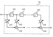
図5は、時変係数フィルタ部50の構成例を示す図である。図5において、時変係数フィルタ部50は、n個の信号遅延部と、n+1個の信号増幅部と、n個の信号加算部とを備えている。なお、図5においては、第1の信号遅延部501、第2の信号遅延部502、第nの信号遅延部503、第1の信号増幅部504、第2の信号増幅部505、第nの信号増幅部506、第1の信号加算部508、および第nの信号加算部509のみを示す。
FIG. 5 is a diagram illustrating a configuration example of the time varying
図5において、各信号遅延部は、従属に接続され、入力した信号を1サンプル遅延させる。各信号増幅部は、入力した信号を増幅して出力する。第1の信号増幅部504は、時変係数フィルタ部50に入力される信号m1を増幅する。第2の信号増幅部505は、第1の信号遅延部501から出力される信号を増幅する。以降、第2の信号増幅部505よりも後段の信号増幅部も第2の信号増幅部505と同様の動作を行う。すなわち、第i+1の信号増幅部は、第iの信号遅延部から出力される信号を増幅する(iは、1からnまでの整数)。第1の信号加算部508は、第1の信号増幅部504から出力される信号と第2の信号増幅部505から出力される信号とを加算する。第2の信号加算部(図示していない)は、第1の信号加算部508から出力される信号と、第3の信号増幅部(図示していない)から出力される信号とを加算する。以降、第2の信号加算部(図示していない)よりも後段の信号加算部も第2の信号加算部と同様の動作を行う。すなわち、第jの信号加算部は、第j−1の信号加算部から出力される信号と、第i+1の信号増幅部から出力される信号とを加算する(jは、2からnまでの整数)。そして、第nの信号加算部509から出力される信号が、出力信号yとなる。なお、図5に示す構成は、一般的なFIR型フィルタの構成であり、第1から第n+1の信号増幅部の各係数は、インパルス応答設計部47からのフィルタ係数hw(n)に従って変化する。
In FIG. 5, each signal delay unit is connected to each other and delays an input signal by one sample. Each signal amplifying unit amplifies and outputs the input signal. The first
図6は、時変係数フィルタ部50の他の構成例を示す図である。図6において、時変係数フィルタ部50は、n個のバンドパスフィルタと、n個の信号増幅部と、信号加算部517とを備えている。なお、図6においては、第1のバンドパスフィルタ511、第2のバンドパスフィルタ512、第nのバンドパスフィルタ513、第1の信号増幅部514、第2の信号増幅部515、第nの信号増幅部516、および信号加算部517のみを示している。
FIG. 6 is a diagram illustrating another configuration example of the time-varying
図6において、各バンドパスフィルタは、入力信号後段に並列に設けられ、時変係数フィルタ部50に入力される信号m1の帯域をn個に分割して出力する。各信号増幅部は、各バンドパスフィルタから出力される信号に対してそれぞれ増幅を行う。信号加算部517は、各信号増幅部から出力される信号を加算し、加算した結果を出力信号yとして出力する。なお、各信号増幅部の増幅率は、フィルタ伝達特性推定部46から出力される伝達関数Hw(ω)をもとに決定することができる。以上の構成によっても、図5と同様の効果を得ることができる。
In FIG. 6, each bandpass filter is provided in parallel in the subsequent stage of the input signal, and divides the band of the signal m <b> 1 input to the time-varying
図7は、図1に示す各信号の具体例を示す図である。具体的には、第1のマイクロホンユニット1から出力される信号m1、第2のマイクロホンユニット2から出力される信号m2、第1の信号減算部30から出力される信号m3、および時変係数フィルタ部50から出力される出力信号yの具体例を示す。図7に示すように、信号m3は、信号m2から反射音等の影響が除去され、目的音以外の成分のみ、すなわち、騒音の成分のみを含む信号となっている。さらに、時変係数フィルタ部50において主信号m1と雑音参照信号m3とを用いてフィルタ処理を行うことによって、出力信号yとして目的音のみを取り出すことができる。従来の指向性マイクロホンユニットの出力であるm1と、実施の形態1のマイクロホン装置の出力信号yとを比較すると明らかなように、実施の形態1のマイクロホン装置によれば、目的音が発生している状態であるか目的音が発生していない状態であるかを問わず、周囲の騒音を大幅に抑圧することができる。
FIG. 7 is a diagram showing a specific example of each signal shown in FIG. Specifically, the signal m1 output from the
なお、第1のマイクロホンユニット1と第2のマイクロホンユニット2との位置関係や、各マイクロホンユニット1および2の後段に設けられる各構成の回路によっては、適応フィルタ収束のための因果律を満たすことを目的として、信号減算部30と第2のマイクロホンユニット2との間に信号遅延部を設ける構成としてもよい。この信号遅延部における遅延量は、各マイクロホンユニット1および2の間の距離を音速で割った量以上とすることを目安として決定される。
Note that, depending on the positional relationship between the
また、実施の形態1では、第1のマイクロホンユニット1として単一指向性マイクロホンユニットを用いることとしたが、無指向性マイクロホンや超指向性マイクロホンを用いてもよい。
In the first embodiment, a unidirectional microphone unit is used as the
なお、上記においては、判定部10は判定結果Vxとして2値で表現される数値を出力した。ここで、判定部10は、多値で表現される信号比率Vaを出力としてもよい。さらに、この場合、適応フィルタ部20は、判定結果(信号比率Va)に応じて学習のスピードを変化させる。具体的には、信号比率Vaがしきい値よりも大きい場合、適応フィルタ部20は、信号比率Vaが大きくなるほど学習のスピードを上げる。より具体的には、適応フィルタ部20は、信号比率Vaが大きくなるほど、ステップゲインパラメータの値を0.5に近づける。一方、信号比率Vaがしきい値以下である場合、適応フィルタ部20は学習を行わない。より具体的には、ステップゲインパラメータの値を0にする。
In the above description, the
以上のように、実施の形態1に係るマイクロホン装置は、騒音環境下および反射音場においても理想的な雑音参照信号を得ることができる。従って、主信号と雑音参照信号とを利用した雑音抑圧部によって、従来の指向性マイクロホンに比較して大幅に収音S/Nを改善することができる。さらに、実施の形態1に係るマイクロホン装置は、雑音抑圧方式として時変係数フィルタを用いた方法を採用することによって、スペクトル減算法を用いる場合に比べて処理遅延を低減することができる。従って、実施の形態1に係るマイクロホン装置は、拡声用途や通話用途等、遅延の少ない処理が要求される用途にも適用することができる。
As described above, the microphone device according to
(実施の形態2)
次に、実施の形態2に係るマイクロホン装置について、図8と図9を用いて説明する。なお、実施の形態1に係るマイクロホン装置は、目的音を検出する際に混入する騒音を抑制することを目的とするものであった。実施の形態2に係るマイクロホン装置は、目的音の反射波が検出されることによる目的音の周波数特性歪みを補正することを目的とするものである。
(Embodiment 2)
Next, a microphone device according to
図8において、マイクロホン装置は、第1のマイクロホンユニット1と、第2のマイクロホンユニット2と、判定部10と、適応フィルタ部20と、信号減算部30と、反射情報算出部60と、反射補正部70とを備えている。なお、図8において、実施の形態1と同様の構成要素については、図1と同じ参照符号を付し、詳細な説明を省略する。
In FIG. 8, the microphone device includes a
図8において、反射情報算出部60には、適応フィルタ部20のフィルタ係数が入力される。反射情報算出部60は、入力されたフィルタ係数を用いて、反射物の有無や、距離、影響度を推定する。反射補正部70は、信号m1を入力として、反射情報算出部60の推定結果に基づいて、目的音の反射の影響によって信号m1に生じている周波数特性歪みを補正する。
In FIG. 8, the filter information of the
以下、実施の形態2に係るマイクロホン装置について動作を説明する。
Hereinafter, the operation of the microphone device according to
図8に示すマイクロホン装置においては、信号m1が主信号となる。ここで、第1のマイクロホンユニット1の指向性が単一指向性である場合、第1のマイクロホンユニット1の指向性は、目的音の反射波を除去できるほど鋭くない。従って、反射物がマイクロホン装置の近傍に存在した場合、目的音の直接波以外に反射波が同時に収音されるので、検出される音の周波数特性が目的音の直接波と反射波との干渉によって乱れることになる。実施の形態2に係るマイクロホン装置は、反射波の情報が適応フィルタ部20のフィルタ係数に表れることを利用して、目的音の反射の影響によって歪んだ周波数特性を補正する。これによって、検出される音の周波数特性の自動補正が可能となる。
In the microphone device shown in FIG. 8, the signal m1 is the main signal. Here, when the directivity of the
前述のように、適応フィルタ部20は、信号m2に混入する目的音成分、すなわち、不完全な指向性による目的音の消し残り成分、および、目的音の反射波成分の信号を生成する。つまり、目的音の直接波の成分を多く含む信号m1から、目的音の反射波の成分を多く含む信号m2への伝達特性(インパルス応答)は、適応フィルタ部20のフィルタ係数に表現されていることになる。従って、このフィルタ係数からその係数のピークを検出することによって、マイクロホンユニットの位置における目的音の直接波が到来する時刻と反射波が到来する時刻との時間差dt(sec)や、反射波を表すピークレベルLrや、反射の強さがわかる。さらに、時間差dtから、目的音の反射波が到来する経路と、直接波が到来する経路との距離差dt×c(ただし、cは音速)がわかる。
As described above, the
ここで、波長が当該距離差と等しくなる(波長λがλ=dt×cの関係を満たす)周波数の音については、直接波と反射波とが同位相で加算されるので、マイクロホンユニットで検出される音圧レベルが上がる。逆に、波長が当該距離差の1/2と等しくなる(波長λがλ/2=dt×cの関係を満たす)周波数の音については、直接波と反射波とが逆位相となるので、マイクロホンユニットで検出される音圧レベルが下がり、主信号の周波数特性においてディップが発生する。また、反射面で完全反射が起こっているとすれば、第1のマイクロホンユニット1から出力される信号には、fa(=c/λ=1/dt)を基本周波数とする高調波部分が強調される、くし型フィルタ状の周波数特性が現れる。
Here, for the sound of the frequency whose wavelength is equal to the distance difference (wavelength λ satisfies the relationship of λ = dt × c), the direct wave and the reflected wave are added in the same phase, and therefore detected by the microphone unit. Increased sound pressure level. Conversely, for a sound having a frequency whose wavelength is equal to 1/2 of the distance difference (wavelength λ satisfies the relationship of λ / 2 = dt × c), the direct wave and the reflected wave are in opposite phases. The sound pressure level detected by the microphone unit decreases, and a dip occurs in the frequency characteristics of the main signal. If complete reflection occurs on the reflecting surface, the signal output from the
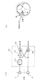
図9は、反射物がある場合と反射物がない場合とにおけるマイクロホン装置の内部状態の相違を説明する図である。図9においては、反射物がある場合と反射物がない場合について、マイクロホンユニット、目的音源(話者)、および反射物の位置関係と、適応フィルタ部20における適応フィルタ係数hadf(n)の値と、信号m1の周波数特性とが示されている。
FIG. 9 is a diagram for explaining the difference in the internal state of the microphone device when there is a reflector and when there is no reflector. In FIG. 9, the positional relationship between the microphone unit, the target sound source (speaker), and the reflector, and the value of the adaptive filter coefficient hadf (n) in the
図9において、(a1)に示すような話者およびマイクロホンユニットの近傍に反射物がない状態においては、(a2)に示すように、適応フィルタ部20のフィルタ係数には、反射波の影響は現れない。さらに、(a3)に示すように、主信号の周波数特性の形状は、比較的平坦になる。一方、(b1)に示すような話者およびマイクロホンの近傍に反射物がある状態においては、(b2)に示すように、適応フィルタ部20のフィルタ係数は、上記時間差dtの部分の値が大きくなる。さらに、(b3)に示すように、主信号の周波数特性に関しても、マイクロホン、目的音源、および反射物の位置関係に応じた周波数特性の歪みが生じている。
In FIG. 9, in the state where there are no reflectors in the vicinity of the speaker and the microphone unit as shown in (a1), as shown in (a2), the influence of the reflected wave on the filter coefficient of the
以上より、適応フィルタの係数ピークから、上記時間差dtや影響度Lrを算出することができる。さらに、これらを用いて、反射波の影響で歪んだ周波数特性の補正量を推定することができる。なお、実際には、特に高音域では、反射面で完全反射が起こっているとみなすことはできない。反射面で完全反射が起こっているとみなすことができない場合には、反射面の反射特性を仮定して、デコンボリューションのフィルタ設計を行うことが考えられる。また、簡易的に低域特性のみに着目して、1波長が距離差に等しい周波数(fa=1/dt)や、1/2波長が距離差に等しい周波数(fb=1/2dt)等の周波数に対して、例えば、以下の式で補正ゲインを算出する。
中心周波数fa:補正ゲイン=−β1・20log(1+α1・Lr)(dB)
中心周波数fb:補正ゲイン=+β2・20log(1−α2・Lr)(dB)
この場合、反射情報算出部60からの情報に基づいて中心周波数とバンド幅とゲインとを調整することが可能なイコライザによって、反射補正部70の補正特性Hr(ω)を実現できる。
As described above, the time difference dt and the influence level Lr can be calculated from the coefficient peak of the adaptive filter. Furthermore, the correction amount of the frequency characteristic distorted by the influence of the reflected wave can be estimated using these. Actually, it cannot be considered that complete reflection occurs on the reflecting surface particularly in a high sound range. In the case where it is not possible to assume that complete reflection occurs on the reflection surface, it is conceivable to perform deconvolution filter design assuming the reflection characteristics of the reflection surface. Further, focusing attention only on the low frequency characteristics, a frequency where one wavelength is equal to the distance difference (fa = 1 / dt), a frequency where the half wavelength is equal to the distance difference (fb = 1/2 dt), etc. For the frequency, for example, the correction gain is calculated by the following equation.
Center frequency fa: correction gain = −β1 · 20 log (1 + α1 · Lr) (dB)
Center frequency fb: correction gain = + β2 · 20 log (1−α2 · Lr) (dB)
In this case, the correction characteristic Hr (ω) of the
なお、例えばカーナビゲーションの音声認識用途でマイクロホン装置を使用する場合等、使用環境が限定できる場合、適応フィルタ部20のフィルタ係数の検出精度を高めることができる。具体的には、初期反射成分のみを対象とし、反射面位置から算出した反射波遅延量に基づいてフィルタ係数の最大値の探索範囲を限定する。
Note that, when the use environment can be limited, for example, when a microphone device is used for voice recognition for car navigation, the detection accuracy of the filter coefficient of the
また、フィルタ係数の最大値は、マイクロホンユニットの指向性タイプによっては、指向性ローブの極性によって、反射波によるピークが正負のどちらに発生するかが反射波の到来方向に依存する場合がある。その様な構成のときには係数の絶対値に対して最大値を探索する必要がある。 In addition, depending on the directivity type of the microphone unit, the maximum value of the filter coefficient may depend on whether the peak due to the reflected wave is positive or negative depending on the direction of the reflected wave depending on the polarity of the directivity lobe. In such a configuration, it is necessary to search for the maximum value with respect to the absolute value of the coefficient.
以上のように、実施の形態2によれば、目的音の反射波の影響で歪む周波数特性を補正することができる。それ故、どの様な使用環境(音場)においても安定して平坦な音圧感度対周波数特性が得られるマイクロホン装置を実現することができる。従って、実施の形態2によれば、通話や拡声においては音質改善を図ることができる。また、特に音声認識用途では反射波が及ぼす周波数特性歪みが誤認識の要因の一つであったが、実施の形態2の構成によって、近傍の反射物の在り無しにかかわらず安定して高い音声認識率を実現することができるようになる。 As described above, according to the second embodiment, it is possible to correct the frequency characteristics that are distorted by the influence of the reflected wave of the target sound. Therefore, it is possible to realize a microphone device that can obtain a stable and flat sound pressure sensitivity versus frequency characteristic in any use environment (sound field). Therefore, according to the second embodiment, it is possible to improve the sound quality in a telephone call or voice expansion. In particular, in frequency recognition applications, frequency characteristic distortion caused by reflected waves was one of the causes of misrecognition. However, the configuration of the second embodiment enables stable and high voice regardless of the presence or absence of nearby reflectors. The recognition rate can be realized.
(実施の形態3)
次に、実施の形態3に係るマイクロホン装置について、図10および図11を用いて説明する。実施の形態3に係るマイクロホン装置は、実施の形態1の構成と実施の形態2の構成とを結合した構成である。
(Embodiment 3)
Next, a microphone device according to
図10は、実施の形態3に係るマイクロホン装置の構成を示すブロック図である。図10において、マイクロホン装置は、第1のマイクロホンユニット1と、第2のマイクロホンユニット2と、判定部10と、適応フィルタ部20と、信号減算部30と、雑音抑圧フィルタ係数算出部40と、時変係数フィルタ部50と、反射情報算出部60と、反射補正部70とを備えている。なお、図10において、実施の形態1または2と同様の構成要素については、図1または図8と同じ参照符号を付し、詳細な説明を省略する。
FIG. 10 is a block diagram showing a configuration of the microphone device according to
図10に示す構成と図8に示す構成との相違点は、図8に示す構成の後段に、図1に示す雑音抑圧フィルタ係数算出部40および時変係数フィルタ部50を設けた点である。これによって、図10に示すマイクロホン装置は、反射波による周波数特性の歪みを補正するとともに、雑音抑圧を行うことが可能である。
The difference between the configuration shown in FIG. 10 and the configuration shown in FIG. 8 is that the noise suppression filter
図11は、実施の形態3に係るマイクロホン装置の他の構成を示すブロック図である。図11において、マイクロホン装置は、第1のマイクロホンユニット1と、第2のマイクロホンユニット2と、判定部10と、適応フィルタ部20と、信号減算部30と、時変係数フィルタ部50と、反射情報算出部60と、反射補正部70と、雑音抑圧かつ反射逆特性フィルタ係数推定部80とを備えている。図11に示す構成は、反射補正部70の特性を時変係数フィルタ部50の特性に重畳させることによって処理量の削減を行う構成である。
FIG. 11 is a block diagram showing another configuration of the microphone device according to
図11に示す構成の動作が図10に示す構成の動作と異なる点は、雑音抑圧かつ反射逆特性フィルタ係数推定部80の動作である。雑音抑圧かつ反射逆特性フィルタ係数推定部80は、信号m1(主信号)と、信号m3(雑音参照信号)と、反射情報算出部60から出力される信号を入力とする。そして、これらの信号に基づいて、雑音抑圧フィルタ特性Hw(ω)=(X(ω)−Nx(ω))/X(ω)と、反射逆特性Hr(ω)を算出する。さらに、{Hw(ω)・Hr(ω)}を目標特性とするフィルタ係数を時変係数フィルタ部50に出力する。これによって、反射波による周波数特性の歪みの補正処理と、雑音抑圧処理とを同時に処理することが可能となる。
The operation of the configuration shown in FIG. 11 is different from the operation of the configuration shown in FIG. 10 in the operation of the noise suppression and reflection inverse characteristic filter
以上のように、実施の形態3によれば、実施の形態1と同様、目的音を除去した理想的な雑音参照信号を得ることができる。また、実施の形態2と同様、主信号と雑音参照信号とを用いた2入力型の雑音抑圧処理と、反射波の影響による周波数特性歪みの補正処理とを同時に行うことができる。その結果、周囲の環境が騒音環境下であっても反射音場であっても、高S/Nでかつ平坦な周波数特性を得ることでき、通話や拡声の音声品質が改善するという効果や、音声認識の認識率が改善するという効果が得られる。 As described above, according to the third embodiment, as in the first embodiment, an ideal noise reference signal from which the target sound is removed can be obtained. Similarly to the second embodiment, the two-input type noise suppression process using the main signal and the noise reference signal and the correction process of the frequency characteristic distortion due to the influence of the reflected wave can be performed simultaneously. As a result, even if the surrounding environment is a noisy environment or a reflected sound field, it is possible to obtain a flat frequency characteristic with a high S / N, and the effect of improving the voice quality of calls and loudspeakers, The effect of improving the recognition rate of voice recognition can be obtained.
(実施の形態4)
次に、実施の形態4に係るマイクロホン装置について、図12および図13を用いて説明する。実施の形態4では、マイクロホン装置に到来する全方向の音の内、目的音とみなす方向を変化させる。
(Embodiment 4)
Next, a microphone device according to
図12は、実施の形態4に係るマイクロホン装置の構成を示すブロック図である。図12において、マイクロホン装置は、図11に示す構成に加え、検出閾値設定部90をさらに備えている。なお、図12において、実施の形態3と同様の構成要素については、図11と同じ参照符号を付し、詳細な説明を省略する。
FIG. 12 is a block diagram showing a configuration of the microphone device according to
検出閾値設定部90は、判定部10において用いられる閾値の値を設定する。つまり、実施の形態4の構成が実施の形態3の構成と異なる点は、判定部10において設定される閾値を制御可能にした点である。
The detection threshold setting unit 90 sets a threshold value used in the
図12においては、判定部10において設定される閾値を変化させることができる。この閾値を変化させることで、目的音とみなす音が到来する方向を、正面方向から左右両側にどの角度まで含めるかを変化させることができる。つまり、この閾値を変化させることで、目的音として収音することが可能な角度の範囲を制御することできる。
In FIG. 12, the threshold set in the
例えば、検出閾値設定部90によって上記閾値をth1と設定した場合(図3参照)を考える。この場合、θ1方向(図2および図3参照)から到来する音は目的音とみなされない。すなわち、θ1方向から到来する音は雑音とみなされ、雑音参照信号である信号m3にはθ1方向から到来する音の成分が含まれることとなる。その結果、最終的な出力においては、θ1方向から到来する音は抑圧されることになる。 For example, consider the case where the detection threshold value setting unit 90 sets the threshold value as th1 (see FIG. 3). In this case, the sound coming from the θ1 direction (see FIGS. 2 and 3) is not regarded as the target sound. That is, the sound coming from the θ1 direction is regarded as noise, and the signal m3 that is the noise reference signal includes a sound component coming from the θ1 direction. As a result, in the final output, the sound coming from the θ1 direction is suppressed.
一方、閾値をth2と設定した場合(図3参照)、θ1方向から到来する音は目的音とみなされる。この場合、雑音参照信号である信号m3にはθ1方向から到来する音の成分が含まれない。その結果、最終的な出力においては、θ1方向から到来する音は目的音として出力されることになる。 On the other hand, when the threshold is set to th2 (see FIG. 3), the sound coming from the θ1 direction is regarded as the target sound. In this case, the signal m3, which is a noise reference signal, does not include a sound component coming from the θ1 direction. As a result, in the final output, the sound arriving from the θ1 direction is output as the target sound.
以上のように、判定部10の閾値を制御することによって、マイクロホン装置が収音可能な角度範囲を制御することが可能となる。ただし、当該角度範囲は、第2のマイクロホンユニット2の指向性死角方向、すなわち正面方向に対してある程度の角度範囲に限られる。
As described above, by controlling the threshold value of the
図13は、マイクロホン装置の指向性パターンを示す図である。図13(a)は、信号m1の指向性パターンを示す図である。図13(b)は、閾値をth2に設定した場合のマイクロホン装置の出力信号yの指向性パターンを示す図である。図13(c)は、閾値をth1に設定した場合のマイクロホン装置の出力信号yの指向性パターンを示す図である。図13(b)においては、マイクロホン装置の収音可能な角度範囲が、図13(c)に比べて広くなる。例えば、しきい値をth2とする場合、角度θ1から到来する音は目的音と判定される。また、当該範囲を外れた部分では大きく感度が減衰している。一方、図13(c)においては、マイクロホン装置の収音可能な角度範囲が狭く、非常に鋭い指向特性が実現されている。この場合、角度θ1から到来する音は目的音と判定されない。 FIG. 13 is a diagram illustrating a directivity pattern of the microphone device. FIG. 13A shows a directivity pattern of the signal m1. FIG. 13B is a diagram showing a directivity pattern of the output signal y of the microphone device when the threshold is set to th2. FIG. 13C is a diagram showing a directivity pattern of the output signal y of the microphone device when the threshold is set to th1. In FIG. 13B, the angle range in which the microphone device can collect sound is wider than that in FIG. For example, when the threshold is set to th2, the sound coming from the angle θ1 is determined as the target sound. In addition, the sensitivity is greatly attenuated at portions outside the range. On the other hand, in FIG. 13C, the angle range in which the microphone device can collect sound is narrow, and a very sharp directional characteristic is realized. In this case, the sound coming from the angle θ1 is not determined as the target sound.
以上のように、実施の形態4によれば、判定部10のしきい値を変化させることによって、マイクロホン装置の指向性の鋭さを変化させることができる。一般的に、マイクロホンの指向性は、鋭い死角を形成するよりも鋭い主ビームを形成するほうが困難であるが、実施の形態4によれば、従来にはない鋭い指向性を有するマイクロホン装置を実現することができる。
As described above, according to the fourth embodiment, the sharpness of the directivity of the microphone device can be changed by changing the threshold value of the
ここで、実使用上では、指向性の鋭さとマイクロホン装置を使用の使いやすさとは相反するものである。ユーザは、鋭い指向性のマイクロホン装置を使用する場合、正面方向を強く意識して用いなければならない。従って、使いやすさと雑音抑圧性能とを両立するためには、マイクロホン装置は、正面からある角度範囲までは一定の感度特性を持ち、それ以外の方向に対する感度減衰が大きくなるような指向特性を有することが望ましい。また、収音可能な角度範囲は、マイクロホン装置の用途や収音状況に応じて自由に設定できることが望ましい。実施の形態4によれば、マイクロホン装置の指向性は図13に示すように変化する。図13から明らかなように、実施の形態4に係るマイクロホン装置は、マイクロホン装置としての使いやすさと、雑音除去能力の高さとを両立することができることがわかる。
Here, in actual use, the sharpness of directivity is contrary to the ease of use of the microphone device. When using a microphone device with a sharp directivity, the user must use it with a strong awareness of the front direction. Therefore, in order to achieve both ease of use and noise suppression performance, the microphone device has a certain sensitivity characteristic from the front to a certain angle range, and a directivity characteristic that increases the sensitivity attenuation in other directions. It is desirable. In addition, it is desirable that the angle range in which sound can be collected can be freely set according to the use of the microphone device and the sound collecting situation. According to the fourth embodiment, the directivity of the microphone device changes as shown in FIG. As can be seen from FIG. 13, the microphone device according to
(実施の形態5)
次に、実施の形態5に係るマイクロホン装置について図14を用いて説明する。なお、実施の形態1〜4に係るマイクロホン装置は、単一指向性マイクロホンユニットと双指向性マイクロホンユニットとを近接して配置し、各マイクロホンユニットから出力される信号を主信号および雑音参照信号とする構成であった。この構成のメリットは、小型化が可能である点、および指向性合成等の処理が不要であるので安価に実現可能である点である。
(Embodiment 5)
Next, a microphone device according to Embodiment 5 will be described with reference to FIG. In the microphone devices according to the first to fourth embodiments, the unidirectional microphone unit and the bidirectional microphone unit are arranged close to each other, and the signals output from the microphone units are the main signal and the noise reference signal. It was the composition to do. The merit of this configuration is that it can be miniaturized and can be realized at low cost because processing such as directivity synthesis is unnecessary.
一方、ビデオムービーやその他の収音機能を有する機器は、実装面の問題や性能面の問題で、しばしば無指向性または同一特性の指向性を持つ複数のマイクロホンユニットが用いられ、これらのマイクロホンユニットから出力される信号の合成によって指向性を形成する場合がある。複数のマイクロホンユニットからの信号に対して指向性合成を行う処理においては、回路雑音等の問題から、マイクロホンユニット間の間隔としてはある程度(通常1cm〜5cm)の間隔が必要とされる。そのため、当該処理を行う方法は、上述した実施の形態1〜4より小型化の面では不利である。しかし、当該処理を行う方法は、指向性の設計自由度が高い点や、デジタル処理を用いた可変特性を利用可能である点等、実装面でメリットがある。 On the other hand, video movies and other devices with sound collection functions often have multiple microphone units with omnidirectionality or directivity with the same characteristics due to mounting problems and performance problems. In some cases, directivity is formed by synthesizing signals output from the. In the process of performing directivity synthesis on signals from a plurality of microphone units, a certain distance (usually 1 cm to 5 cm) is required as a distance between the microphone units due to problems such as circuit noise. Therefore, the method of performing the process is disadvantageous in terms of downsizing compared to the above-described first to fourth embodiments. However, the method of performing the processing has advantages in terms of mounting, such as a high degree of freedom in design of directivity and the ability to use variable characteristics using digital processing.
そこで、実施の形態5においては、同一の指向特性を持つ複数のマイクロホンユニット(実施の形態5では2個)と、指向性合成部100とを用いて、上記信号m1に相当する主信号と、上記信号m2に相当する雑音参照信号とを得る構成を採用する。
Therefore, in the fifth embodiment, using a plurality of microphone units having the same directivity characteristics (two in the fifth embodiment) and the
図14は、実施の形態5に係るマイクロホン装置の構成の一部を示す図である。図14において、マイクロホン装置は、第3のマイクロホンユニット3と、第4のマイクロホンユニット4と、指向性合成部100とを備えている。なお、信号m1および信号m2を得た後の構成は、実施の形態1〜4のいずれかの構成が用いられる。
FIG. 14 is a diagram showing a part of the configuration of the microphone device according to Embodiment 5. In FIG. In FIG. 14, the microphone device includes a
図14において、各マイクロホンユニット3および4は、正面方向を向く軸(図14に示す一点鎖線)上に配置される。各マイクロホンユニット3および4の間の距離はdである。各マイクロホンユニット3および4は、その指向性主軸が正面方向を向くように配置される。
In FIG. 14, each of the
また、指向性合成部100は、第1の信号遅延部101と、第1の信号減算部103と、第2の信号遅延部102と、第2の信号減算部104とを備えている。第1の信号遅延部101は、第4のマイクロホンユニット4から出力される信号を遅延させる。第2の信号遅延部102は、第3のマイクロホンユニット3から出力される信号を遅延させる。第1の信号減算部103は、第3のマイクロホンユニット3から出力される信号から、第1の信号遅延部101から出力される信号を減算する。これによって信号m1が得られる。第2の信号減算部104は、第4のマイクロホンユニット4から出力される信号から、第2の信号遅延部102から出力される信号を減算する。これによって、信号m2が得られる。
The
また、第1の信号遅延部101の遅延量τ1を0≦τ1≦d/c(ただし、cは音速)とすることによって、指向性主軸が正面方向となる2次音圧傾度型の超指向性特性を信号m1として得ることができる。また、第2の信号遅延部102の信号遅延量τ2をτ2=d/cとすることによって、正面方向に指向性の死角が形成される信号(正面方向に指向性の死角が形成されるマイクロホンユニットからの結果として得られる信号)m2を得ることができる。
Further, by setting the delay amount τ1 of the first
以上の構成により、信号m1の特性に予め超指向性を実現することで、後段の雑音抑圧処理と組み合わせ、従来の超指向性マイクロホンを大幅に上回る鋭い指向性と雑音抑圧性能を実現することができる。 With the above configuration, by realizing superdirectivity in advance in the characteristics of the signal m1, it is possible to realize sharp directivity and noise suppression performance that greatly exceed conventional superdirective microphones in combination with subsequent noise suppression processing. it can.
(実施の形態6)
次に、実施の形態6に係るマイクロホン装置について図15を用いて説明する。実施の形態6は、実施の形態5と同様、同一の指向特性を持つ複数のマイクロホンユニットを用いて、主信号と雑音参照信号とを得る構成を採用するものである。
(Embodiment 6)
Next, a microphone device according to Embodiment 6 will be described with reference to FIG. As in the fifth embodiment, the sixth embodiment employs a configuration in which a main signal and a noise reference signal are obtained using a plurality of microphone units having the same directivity characteristics.
図15は、実施の形態6に係るマイクロホン装置の構成の一部を示す図である。マイクロホン装置は、第3のマイクロホンユニット3と、第4のマイクロホンユニット4と、指向性合成部100とを備えている。各マイクロホンユニット3および4は、正面方向を向く直線(図15に示す点線)に垂直な軸(図15に示す一点鎖線)上に配置される。各マイクロホンユニット3および4は、その指向性主軸が正面方向を向くように配置される。なお、信号m1および信号m2を得た後の構成は、実施の形態1〜4のいずれかの構成が用いられる。
FIG. 15 is a diagram showing a part of the configuration of the microphone device according to Embodiment 6. In FIG. The microphone device includes a
図15において、指向性合成部100は、第1の信号加算部105と、第2の信号減算部104とを備えている。第1の信号加算部105は、各マイクロホンユニット3および4から出力される信号を加算する。これによって主信号である信号m1を得ることができる。第2の信号減算部104は、第4のマイクロホンユニット4から出力される信号から第3のマイクロホンユニット3から出力される信号を減算する。これによって、雑音参照信号である信号m2を得ることができる。
In FIG. 15, the
図15において、各マイクロホンユニット3および4の間隔がある程度狭い場合、信号m1の指向特性は、マイクロホンユニット単体の場合(実施の形態1〜4)と高域特性を除いてあまり変わらない。従って、図15に示す構成では、図14に示す構成と比較して鋭い指向性を得ることはできないが、その半面、振動雑音や回路雑音の低減効果が得られる。また、正面方向から到来した音は各マイクロホンユニット3および4で同位相で検出されるので、正面方向に指向性の死角が形成された信号m2を得ることができる。
In FIG. 15, when the distance between the
(実施の形態7)
次に、実施の形態7に係るマイクロホン装置について図16を用いて説明する。実施の形態7は、実施の形態5と同様、同一の指向特性を持つ複数のマイクロホンユニットを用いて、主信号と雑音参照信号とを得る構成を採用するものである。
(Embodiment 7)
Next, a microphone device according to Embodiment 7 will be described with reference to FIG. As in the fifth embodiment, the seventh embodiment employs a configuration in which a main signal and a noise reference signal are obtained using a plurality of microphone units having the same directivity characteristics.
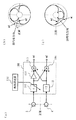
図16(a)は、実施の形態7に係るマイクロホン装置の構成の一部を示す図である。マイクロホン装置は、第3のマイクロホンユニット3と、第4のマイクロホンユニット4と、指向性合成部100とを備えている。各マイクロホンユニット3および4の配置は、図15に示す配置と同様である。なお、信号m1および信号m2を得た後の構成は、実施の形態1〜4のいずれかの構成が用いられる。
FIG. 16A shows a part of the configuration of the microphone device according to the seventh embodiment. The microphone device includes a
図16(a)において、指向性合成部100は、信号遅延部111と、第2の信号減算部104と、信号増幅部150と、第1の信号減算部103とを備えている。信号遅延部111は、第3のマイクロホンユニット3から出力される信号を入力として信号を遅延させる。第2の信号減算部104は、第4のマイクロホンユニット4から出力される信号から、信号遅延部111から出力される信号を減算する。これによって雑音参照信号である信号m2を得ることができる。信号増幅部150は、信号遅延部111から出力される信号を定数倍する。第1の信号減算部103は、第4のマイクロホンユニット4から出力される信号から、信号増幅部150から出力される信号を減算する。これによって、主信号である信号m1を得ることができる。
In FIG. 16A, the
図16(a)において、信号m1を得る過程と信号m2を得る過程との違いは、信号m1を得る過程には信号増幅部150が存在することである。信号m1および信号m2における指向性の死角方向は、信号遅延部111の遅延量τ1によって決まる。例えば、τ1=0である場合、指向性の死角は正面方向となり、τ1=d/cである場合、指向性の死角は正面方向に垂直な方向となる。ここでは、目的音の方向に死角ができるように遅延量τ1を設定する。これによって、信号m1および信号m2には、目的音方向以外の他の方向から到来する音の成分が目的音の成分よりも多く含まれることになる。
In FIG. 16A, the difference between the process of obtaining the signal m1 and the process of obtaining the signal m2 is that the
ここで、指向性合成部100で形成される指向性パターンは、目的音の方向については、信号m1と信号m2との間で感度差が大きいことが好ましい。一方、目的音の方向以外の方向については、信号m1と信号m2との間で感度特性に差がないことが好ましい。これは、複数方向から同時に騒音が到来している状況で、雑音参照信号をもとに主信号に混入する雑音成分を抑圧するためには、図4に示すスペクトル比演算部43の出力が、雑音が到来する方向にかかわらず一定となる必要があるからである。すなわち、スペクトル比演算部43の出力が雑音の到来方向によって変化すると、ある特定の方向の推定雑音スペクトルNx(ω)しか正確に求まらないことになるからである。従って、信号m1と信号m2との指向性パターンは、指向性の死角部分のみにおいて形状が異なり、他の部分では形状が同じになることが好ましい。
Here, the directivity pattern formed by the
ここで、各マイクロホンユニット3および4からの信号を減算するときに第3のマイクロホンユニット3と第4のマイクロホンユニット4との感度のバランスを崩すと、最も精度が必要な零点、すなわち指向性の死角の部分の感度が上昇する。この性質を利用して、信号m1側に信号増幅部150を設け、信号増幅率を0.85程度に設定することによって、図16(b)に示すような指向性パターンを得ることができる。図16(b)は、図16(a)における信号m1および信号m2における指向性パターンを示す図である。図16(b)に示すように、実施の形態7においては、指向性の死角部分のみにおいて形状が異なり、他の部分では形状がほぼ同じになる指向性パターンを得ることができる。
Here, if the balance of sensitivity between the
以上のように、実施の形態7によれば、目的音方向に関してのみ感度特性が異なる信号m1および信号m2を得ることができる。そのため、後段の雑音抑圧処理において良好な抑圧効果を得ることができるようになる。 As described above, according to the seventh embodiment, it is possible to obtain the signal m1 and the signal m2 having different sensitivity characteristics only with respect to the target sound direction. Therefore, a good suppression effect can be obtained in the subsequent noise suppression processing.
(実施の形態8)
次に、実施の形態8に係るマイクロホン装置について図17を用いて説明する。実施の形態8は、実施の形態5と同様、同一の指向特性を持つ複数のマイクロホンユニットを用いて、主信号と雑音参照信号とを得る構成を採用するものである。
(Embodiment 8)
Next, a microphone device according to
図17(a)は、実施の形態8に係るマイクロホン装置の構成の一部を示す図である。図17(a)において、指向性合成部100は、図16(a)に示す構成に加え、角度設定部160と、第2の信号遅延部112をさらに備えている。なお、信号m1および信号m2を得た後の構成は、実施の形態1〜4のいずれかの構成が用いられる。
FIG. 17A shows a part of the configuration of the microphone device according to
図17(a)に示す構成は、角度設定部160をさらに設けるとともに、第4のマイクロホンユニット4の後段に第2の信号遅延部112を設けた点で図16(a)に示す構成と異なる。なお、図17(a)における基本的な動作は図16(a)と同様なので省略する。図17(a)における動作のうち図16(a)における動作と異なる点は、角度設定部160によって、目的音方向を変化させることができるようにした点である。
The configuration shown in FIG. 17A is different from the configuration shown in FIG. 16A in that an
角度設定部160は、第1の信号遅延部111の信号遅延量τ1を、0≦τ1≦2d/c(ただし、dはマイクロホンユニットの間隔、cは音速)の範囲で変化させることができるものとする。ここで、第2の信号遅延部112がない場合、第1の信号遅延部111の信号遅延量τ1を上記の範囲で変化させても、正面方向に対して0°から+90°までの範囲でしか目的音方向を変化させることができない。そこで、第2の信号遅延部112を設け、その信号遅延量τ2をτ2=d/cとすることによって、正面方向に対して±90°の範囲で目的音方向を変化させることとしている。
The
以上のように、実施の形態8においては、マイクロホン装置の収音方向(目的音方向)を可変にすることが可能となる。例えば、図17(b)に示す指向性パターンを実現することも可能であるし、信号遅延部の信号遅延量を変化させることによって、図17(c)に示す指向性パターンを実現することも可能である。なお、可変遅延特性は、信号遅延部をオールパスフィルタH(ω)=(A+z−1)/(1+A・z−1)で構成し、係数Aを0≦A<1とすることによって簡単に実現することができる。信号遅延量を変化させる際には、角度設定部160によってこの係数Aを変化させる。なお、大きな遅延量や、遅延周波数特性の直線性が必要なときには、2次オールパスフィルタおよび/またはオールパスフィルタを従属接続すればよい。
As described above, in the eighth embodiment, the sound collection direction (target sound direction) of the microphone device can be made variable. For example, the directivity pattern shown in FIG. 17B can be realized, or the directivity pattern shown in FIG. 17C can be realized by changing the signal delay amount of the signal delay unit. Is possible. The variable delay characteristic is easily realized by configuring the signal delay unit with an all-pass filter H (ω) = (A + z−1) / (1 + A · z−1) and setting the coefficient A to 0 ≦ A <1. can do. When changing the signal delay amount, the coefficient A is changed by the
(実施の形態9)
次に、実施の形態9に係るマイクロホン装置について図18を用いて説明する。実施の形態9は、実施の形態5と同様、同一の指向特性を持つ複数のマイクロホンユニットを用いて、主信号と雑音参照信号とを得る構成を採用するものである。
(Embodiment 9)
Next, a microphone device according to Embodiment 9 will be described with reference to FIG. As in the fifth embodiment, the ninth embodiment employs a configuration in which a main signal and a noise reference signal are obtained using a plurality of microphone units having the same directivity characteristics.
図18(a)は、実施の形態9に係るマイクロホン装置の構成の一部を示す図である。マイクロホン装置は、第3のマイクロホンユニット3と、第4のマイクロホンユニット4と、指向性合成部100と、角度設定部160とを備えている。各マイクロホンユニット3および4の配置は、図15に示す配置と同様である。なお、信号m1および信号m2を得た後の構成は、実施の形態1〜4のいずれかの構成が用いられる。
FIG. 18A illustrates a part of the configuration of the microphone device according to the ninth embodiment. The microphone device includes a
図18(a)において、指向性合成部100は、第3の信号遅延部121と、第1の信号遅延部101と、第4の信号遅延部122と、第2の信号遅延部102と、第1の信号減算部103と、第2の信号減算部104とを備えている。第3の信号遅延部121は、第3のマイクロホンユニット3から出力される信号を遅延させる。第1の信号遅延部101は、第4のマイクロホンユニット4から出力される信号を遅延させる。第1の信号減算部103は、第3の信号遅延部121から出力される信号から、第1の信号遅延部101から出力される信号を減算する。これによって、主信号である信号m1を得ることができる。第4の信号遅延部122は、第4のマイクロホンユニット4から出力される信号を遅延させる。第2の信号遅延部102は、第3のマイクロホンユニット3から出力される信号を遅延させる。第2の信号減算部104は、第4の信号遅延部122から出力される信号から、第2の信号遅延部102から出力される信号を減算する。これによって、雑音参照信号である信号m2を得ることができる。角度設定部160は、第1の信号遅延部101の信号遅延量と、第2の信号遅延部102の信号遅延量とを独立して制御する。
18A, the
図18(a)において、信号m1側の構成は、信号m2側の構成に対して対称的に構成される。これによって、信号m1の指向性パタンと信号m2の指向性パターンとは独立に制御されるので、信号m1および信号m2の指向性パターンを、目的音方向の感度に重点を置く設計とすることができる。具体的には、信号m1の指向性パターンを図18(b)に示すように、目的音方向でできるだけ感度が高く、かつ雑音抑圧効果が得られる指向性とする。さらに、信号m2の指向性パターンを図18(c)に示すように、指向性の死角方向を目的音方向に一致させるように形成する。 In FIG. 18A, the configuration on the signal m1 side is configured symmetrically with respect to the configuration on the signal m2 side. As a result, the directivity pattern of the signal m1 and the directivity pattern of the signal m2 are controlled independently. Therefore, the directivity patterns of the signal m1 and the signal m2 may be designed to emphasize the sensitivity in the target sound direction. it can. Specifically, as shown in FIG. 18B, the directivity pattern of the signal m1 has a directivity that is as sensitive as possible in the target sound direction and that provides a noise suppression effect. Further, as shown in FIG. 18C, the directivity pattern of the signal m2 is formed so that the blind spot direction of directivity coincides with the target sound direction.
以上のように、実施の形態9では、後段の雑音抑圧処理を補助的に用い、前段の指向性合成によって雑音を積極的に抑圧する。そのため、実施の形態9では信号m1の指向性パターンを優先して形成する。ここで、指向性合成は線形処理であるので、音声波形歪などを起こしにくいという特徴がある。一方、雑音抑圧処理は、フィルタ係数が時間的に変化する非線形処理であるので、雑音スペクトル等様々な推定部の誤差によって、音声波形歪を生じる場合がある。このように観点から、図17(b)および(c)に示す指向性パターンを採用するか、図18(b)および(c)に示す指向性パターンを採用するかについては、使用環境(目的音の大きさ、周囲騒音レベル、反射、残響等)や、用途(通話、音声認識、録音等)や、必要とする雑音抑圧量等によって、適宜選択することが好ましい。 As described above, in the ninth embodiment, the noise suppression process at the subsequent stage is supplementarily used, and noise is positively suppressed by the directivity synthesis at the previous stage. Therefore, in the ninth embodiment, the directivity pattern of the signal m1 is formed with priority. Here, since the directivity synthesis is a linear process, there is a feature that speech waveform distortion or the like hardly occurs. On the other hand, the noise suppression process is a non-linear process in which the filter coefficient changes with time, so that there are cases where speech waveform distortion occurs due to errors of various estimation units such as a noise spectrum. From this point of view, whether to use the directivity pattern shown in FIGS. 17B and 17C or the directivity pattern shown in FIGS. 18B and 18C depends on the usage environment (purpose It is preferable to select appropriately according to the volume of sound, ambient noise level, reflection, reverberation, etc.), application (calling, voice recognition, recording, etc.), required noise suppression amount, and the like.
(実施の形態10)
次に、実施の形態10に係るマイクロホン装置について図19を用いて説明する。実施の形態10では、2つのマイクロホンユニットの指向性主軸が異なる方向を向いて設けられている機器において、本発明の雑音抑制処理に必要な主信号および雑音参照信号を得ることを目的とする。
(Embodiment 10)
Next, a microphone device according to
図19は、実施の形態10に係るマイクロホン装置の構成の一部を示す図である。マイクロホン装置は、第3のマイクロホンユニット3と、第4のマイクロホンユニット4と、指向性再合成部200とを備えている。なお、信号m1および信号m2を得た後の構成は、実施の形態1〜4のいずれかの構成が用いられる。
FIG. 19 is a diagram illustrating a part of the configuration of the microphone device according to the tenth embodiment. The microphone device includes a
図19において、各マイクロホンユニット3および4が配置される位置は、図15に示す位置と同様である。ただし、図19においては、第3のマイクロホンユニット3は、正面方向に対して所定の角度だけ回転した方向に指向性主軸が向けられている。第4のマイクロホンユニット4は、正面方向に対して所定の角度だけ回転(第3のマイクロホンユニット3とは逆の回転方向)した方向に指向性主軸が向けられている。ここで、第3のマイクロホンユニット3から出力される信号を右チャンネル信号と呼び、第4のマイクロホンユニット4から出力される信号を左チャンネル信号と呼ぶ。
In FIG. 19, the positions where the
また、図19において、指向性再合成部200は、信号加算部205と、信号減算部204とを備えている。信号加算部205は、右チャンネル信号と左チャンネル信号とを加算する。これによって主信号である信号m1を得ることができる。信号減算部204は、左チャンネル信号から右チャンネル信号を減算する。これによって雑音参照信号である信号m2を得ることができる。
In FIG. 19, the
なお、図19の構成は、例えばビデオムービーの様にワンポイントステレオマイクロホンが用いられている機器に本発明を適用することを想定している。例えば、この機器では、通常はステレオ収音を行い、目的音として正面方向のみを強調する場合には以下に説明するような指向性の再合成を行うようにしてもよい。 Note that the configuration of FIG. 19 assumes that the present invention is applied to a device in which a one-point stereo microphone is used, such as a video movie. For example, in this device, stereo sound collection is usually performed, and when only the front direction is emphasized as the target sound, re-synthesis of directivity as described below may be performed.
通常のワンポイントステレオマイクロホンでは、再生時の音像定位を考慮に入れて、中央(図19に示す正面方向)から到来する音の位相が左右のマイクロホンユニットにおいて同位相となるように、左右のマイクロホンユニットの振幅および位相特性は同一のものが用いられる。また、上述したように、各マイクロホンユニット3および4の指向性の角度は、左右のマイクロホンユニットで等しい角度に設定される。従って、信号加算部205において右チャンネル信号と左チャンネル信号とを加算することによって、正面方向に指向性がある信号m1が得られる。また、信号減算部204において、左チャンネル信号から右チャンネル信号を減算することによって、正面方向に指向性死角を持つ信号m2が得られる。以上のように、指向性再合成部200によって生成される信号m1および信号m2は、それぞれ、実施の形態1の信号m1および信号m2と同様の信号となる。従って、信号m1および信号m2を用いて雑音抑圧処理や反射特性歪みの補正処理を行うことが可能である。
In a normal one-point stereo microphone, the left and right microphones are arranged so that the sound coming from the center (front direction shown in FIG. 19) has the same phase in the left and right microphone units, taking into account the sound image localization during playback. The unit has the same amplitude and phase characteristics. Further, as described above, the directivity angles of the
以上のようにして、実施の形態10によれば、ワンポイントステレオマイクロホンから出力される信号を利用して、目的音方向の音を強調することができる。従って、ワンポイントステレオマイクロホンを有する機器を例えばズームマイクロホンとして機能させることが可能となる。また、実施の形態10では、ステレオ信号をもとにして指向性の再合成を行うので、ステレオ信号と正面方向の信号とが同時に得られるマルチチャンネル収音にも応用が可能となる。なお、ステレオマイクはアナログ回路であっても、上記と同様の効果を得ることができる。
As described above, according to the tenth embodiment, the sound in the target sound direction can be enhanced using the signal output from the one-point stereo microphone. Therefore, a device having a one-point stereo microphone can function as a zoom microphone, for example. In
(実施の形態11)
次に、実施の形態11に係るマイクロホン装置について図20を用いて説明する。実施の形態11では、ステレオ信号が生成される機器において、本発明の雑音抑制処理に必要な主信号および雑音参照信号を得ることを目的とする。
(Embodiment 11)
Next, a microphone device according to Embodiment 11 will be described with reference to FIG. The object of the eleventh embodiment is to obtain a main signal and a noise reference signal necessary for noise suppression processing of the present invention in a device that generates a stereo signal.
図20は、実施の形態11に係るマイクロホン装置の構成を示す図である。図20において、マイクロホン装置は、第5のマイクロホンユニット5と、第6のマイクロホンユニット6と、指向性合成部500と、指向性再合成部200とを備えている。各マイクロホンユニット5および6は、同一特性の無指向性マイクロホンユニットである。各マイクロホンユニット5および6の配置位置は、図15に示す配置と同様である。指向性合成部500は、各マイクロホンユニット5および6から出力される信号を入力として、右チャンネル信号Rchおよび左チャンネル信号Lchを出力する。指向性再合成部200は、右チャンネル信号Rchおよび左チャンネル信号Lchを入力として、目的音方向に感度を持つ主信号である信号m1と、目的音方向に指向性死角を持つ雑音参照信号である信号m2とを出力する。なお、目的音方向は、正面方向以外の方向も設定可能とする。
FIG. 20 is a diagram showing a configuration of the microphone device according to Embodiment 11. In FIG. 20, the microphone device includes a fifth microphone unit 5, a sixth microphone unit 6, a
また、図20において、指向性再合成部200は、逆指向性合成部250と、指向性合成部100とを備えている。逆指向性合成部250は、指向性合成部500から出力される信号(右チャンネル信号Rchおよび左チャンネル信号Lch)を入力とする。逆指向性合成部250は、右チャンネル信号Rchおよび左チャンネル信号Lchから、無指向性の信号を生成する。指向性合成部100は、実施の形態5において示したものと同様である。ただし、ここでは、角度設定部160は設けられていない構成とする。また、図20では、指向性合成部100を図18(a)に示す構成としたが、指向性合成部100は、図15、図16(a)、および図17(a)に示す構成であってもよい。
In FIG. 20, the
実施の形態11では、指向性合成部500によって得られたステレオ信号(右チャンネル信号Rchおよび左チャンネル信号Lch)が、逆指向性合成部250によって各マイクロホンユニット5および6から出力された信号に再変換される。つまり、ステレオ信号は、2つの無指向性の信号に再変換される。さらに、再変換によって得られた無指向性の信号は、指向性合成部100によって所定の方向から到来する目的音を検出するための主信号および雑音参照信号に変換される。
In the eleventh embodiment, the stereo signals (right channel signal Rch and left channel signal Lch) obtained by
ここで、ステレオ信号を出力するための指向性合成部500は、第1の信号遅延部501と、第1の信号減算部521と、第2の信号遅延部502と、第2の信号減算部522とから構成される。第1の信号遅延部501は、第6のマイクロホンユニット6から出力される信号を遅延して出力する。第1の信号減算部521は、第5のマイクロホンユニット5から出力される信号から、第1の信号遅延部501から出力される信号を減算し、減算の結果得られた信号Rchを出力する。第2の信号遅延部502は、第5のマイクロホンユニット5から出力される信号を遅延して出力する。第2の信号減算部522は、第6のマイクロホンユニット6から出力される信号から、第2の信号遅延部502から出力される信号を減算し、減算の結果得られた信号Lchを出力する。以上に述べた指向性合成部500の動作を数式で表現すると、次のようになる。

以上のように、実施の形態11では、ワンポイントステレオマイクロホンから出力される信号を利用する。この場合でも、実施の形態10と同様の効果を得ることができる。すなわち、正面方向から到来する目的音の強調、および反射による周波数歪みの補正を行うことができる。また、実施の形態11では、任意の方向から到来する目的音に対応することができる。 As described above, in the eleventh embodiment, a signal output from the one-point stereo microphone is used. Even in this case, an effect similar to that of the tenth embodiment can be obtained. That is, the target sound coming from the front direction can be emphasized and frequency distortion due to reflection can be corrected. In the eleventh embodiment, it is possible to deal with a target sound coming from an arbitrary direction.
実施の形態11は、特に、マイクロホンユニットから出力される信号が得られず、ステレオ化された信号のみが入手可能な状態で有効である。換言すれば、実施の形態11によれば、ステレオ化された信号が生成される機器においても、目的音の主信号および理想的な雑音参照信号を得るための構成を実現することができる。 The eleventh embodiment is particularly effective when a signal output from the microphone unit cannot be obtained and only a stereo signal is available. In other words, according to the eleventh embodiment, a configuration for obtaining a main signal of an objective sound and an ideal noise reference signal can be realized even in a device that generates a stereo signal.
図21は、実施の形態11の応用例を示す図である。図21は、音声記録装置801と、音声再生装置802とからなるシステムを示す図である。音声記録装置801は、第5および第6のマイクロホンユニット5および6と、指向性合成部500とを備えている。また、記録部803は、音声記録装置801および音声再生装置802に着脱可能な記録媒体である。音声再生装置802は、指向性再合成部200とを備えている。また、図示していないが、音声再生装置802は、実施の形態1〜4のいずれかのマイクロホン装置の構成を備えている。
FIG. 21 is a diagram illustrating an application example of the eleventh embodiment. FIG. 21 is a diagram showing a system including an
図21において、音声記録装置801の記録部803には、信号Rchおよび信号Lchが記録される。これによって、記録部803に音声情報が記録されたことになる。音声情報が記録された記録部803が音声再生装置802に装着されると、音声再生装置802は、記録部803に記録されている情報を読み出す。具体的には、信号Rchおよび信号Lchが指向性再合成部200に読みとられる。指向性再合成部200は、読みとった信号Rchおよび信号Lchから、主信号および雑音参照信号を生成する。主信号および雑音参照信号を用いることによって、目的音に対する雑音抑圧処理を行うことができる。
In FIG. 21, a signal Rch and a signal Lch are recorded in the
以上のように、音声記録装置801と音声再生装置802とが別体である場合でも、実施の形態11の構成を実現することができる。すなわち、ビデオムービー等の記録部803に一度記録された信号に対して、再生時に雑音抑圧処理を行うようにすることも可能である。
As described above, even when the
図22は、図21に示す音声再生装置の応用例を示す図である。図22においては、音声再生装置802は、図21において説明した構成に加え、画像表示部900および角度設定部160を備えている。すなわち、図22に示す音声再生装置802は画像表示機能を備えており、例えば、デジタルビデオカメラ等によって実現される。
FIG. 22 is a diagram illustrating an application example of the audio reproduction device illustrated in FIG. 21. In FIG. 22, the
図22においては、記録部803には、図21において説明した音声情報の他、画像表示部に表示すべき画像情報を記録している。この音声情報および画像情報は、例えばデジタルビデオカメラで同時に記録された画像(映像)および音声の情報のように、互いに関連する情報である。この音声情報および画像情報は、音声再生装置802において同時に再生される。ここで、音声情報および画像情報の再生中において、ユーザは角度設定部160を用いて角度を指示する。このとき、ユーザは、画像表示部に表示された画像を見ながら角度を決定する。例えば、画像表示部の画面中央に被写体が表示されているならば、ユーザは、画面中央に対応する方向(すなわち、正面方向)を示す角度を指示する。これによって、ユーザは、正面方向から到来する音を目的音として抽出して聞くことができる。
In FIG. 22, the
なお、他の実施の形態においては、次のような構成も考えられる。図23は、他の実施の形態におけるマイクロホン装置の構成の一部を示す図である。図23において、第5のマイクロホンユニット5、第6のマイクロホンユニット6、および指向性合成部500については、図20に示す構成と同様である。また、指向性再合成部200については、図19に示す構成と同様である。図23に示す構成によっても、上記と同様の効果を得ることができる。なお、信号m1および信号m2を得た後の構成は実施の形態1〜4のいずれかの構成が用いられる。
In other embodiments, the following configuration is also conceivable. FIG. 23 is a diagram illustrating a part of the configuration of a microphone device according to another embodiment. In FIG. 23, the fifth microphone unit 5, the sixth microphone unit 6, and the
以上のように、本発明によれば、目的音方向に向けた指向性マイクロホン出力に対して、目的音方向以外の方向について定常および非定常雑音を抑圧することで、小型でありながら超指向性を持つマイクロホンを得ることができる。また、同時にマイクロホン装置が受ける反射波の周波数特性への影響を除去することができる。このように効果から、加法性雑音である騒音と、乗法性雑音である反射波との両方を同時に抑圧可能となり、音場の影響を受けず高S/Nでかつ常に平坦なマイクロホン周波数特性を実現することができる。また雑音抑圧処理部においては、処理遅延を少なくする構成を実現することで、大きな遅延が許されない拡声や通話への応用を可能とする。また、前処理となる指向性合成、逆指向性合成、指向性再合成などの組み合わせにより様々な方向の音を抽出したり再生装置側での同様の効果も得られる。 As described above, according to the present invention, with respect to the directional microphone output directed toward the target sound direction, the stationary and non-stationary noises are suppressed in directions other than the target sound direction. A microphone with can be obtained. At the same time, the influence on the frequency characteristic of the reflected wave received by the microphone device can be removed. In this way, both additive noise and multiplicative noise reflected waves can be suppressed simultaneously, and high S / N and always flat microphone frequency characteristics are not affected by the sound field. Can be realized. In addition, the noise suppression processing unit realizes a configuration that reduces a processing delay, thereby enabling application to a loud voice or a call that does not allow a large delay. In addition, sound in various directions can be extracted by combining combinations of directivity synthesis, reverse directivity synthesis, and directivity resynthesis, which are preprocessing, and similar effects can be obtained on the playback device side.
以上のように、本発明のマイクロホン装置および再生装置は、実使用環境の複数の騒音下でも安定に動作するとともに、高S/Nを実現すること等を目的として利用することが可能である。 As described above, the microphone device and the playback device of the present invention can be used for the purpose of stably operating even under a plurality of noises in an actual use environment and realizing a high S / N.
1 第1のマイクロホンユニット
2 第2のマイクロホンユニット
3 第3のマイクロホンユニット
4 第4のマイクロホンユニット
10 判定部
20 適応フィルタ部
30 信号減算部
40 雑音抑圧フィルタ係数算出部
50 時変係数フィルタ部
60 反射情報算出部
70 反射補正部
90 検出閾値設定部
DESCRIPTION OF
Claims (15)
目的音方向に対して感度を有して検出した結果を示す主信号と、目的音方向に対して感度死角を向けて検出した結果を示す雑音参照信号とを生成する信号生成部と、
前記信号生成部によって生成された雑音参照信号の信号レベルに対する前記主信号の信号レベルの割合を示すレベル比が所定の値よりも大きいか否かを判定する判定部と、
前記信号生成部によって生成された主信号を適応フィルタでフィルタリングすることによって、前記信号生成部によって生成された雑音参照信号に含まれる目的音の信号成分を示す信号を生成するとともに、前記判定部によって前記レベル比が所定の値よりも大きいと判定された場合のみ、フィルタ係数の学習を行う適応フィルタ部と、
前記雑音参照信号から、前記適応フィルタ部によって生成された、前記雑音参照信号に含まれる目的音の信号成分を示す信号を減算する減算部と、
前記主信号と、前記減算部による減算後の雑音参照信号とを用いて、主信号に含まれる雑音の信号成分を抑圧する雑音抑圧部を備え、
前記雑音抑圧部は、前記主信号と前記減算部による減算後の雑音参照信号とに基づいて、前記主信号から目的音の信号以外の信号成分を抑圧するための雑音抑圧フィルタのフィルタ係数を算出する雑音抑圧フィルタ係数算出部と、
前記雑音抑圧フィルタ係数算出部によって算出されたフィルタ係数を反映して、前記主信号に対してフィルタリングを行う時変係数フィルタ部とを含む、マイクロホン装置。 A microphone device for detecting a target sound coming from a target sound direction,
A signal generation unit that generates a main signal indicating a result detected with sensitivity to the target sound direction , and a noise reference signal indicating a result detected by directing the sensitivity blind angle with respect to the target sound direction;
A determination unit that determines whether a level ratio indicating a ratio of the signal level of the main signal to the signal level of the noise reference signal generated by the signal generation unit is greater than a predetermined value;
The main signal generated by the signal generation unit is filtered by an adaptive filter to generate a signal indicating the signal component of the target sound included in the noise reference signal generated by the signal generation unit, and by the determination unit An adaptive filter unit that learns filter coefficients only when the level ratio is determined to be greater than a predetermined value;
Before Kizatsu sound reference signal, the generated by the adaptive filter section, and a subtraction unit for subtracting a signal indicating the signal components of the target sound included in the noise reference signal,
Using the main signal and a noise reference signal after subtraction by the subtraction unit, a noise suppression unit that suppresses a signal component of noise included in the main signal ,
The noise suppression unit calculates a filter coefficient of a noise suppression filter for suppressing signal components other than the target sound signal from the main signal based on the main signal and the noise reference signal after subtraction by the subtraction unit. A noise suppression filter coefficient calculation unit for
A microphone device , comprising: a time-varying coefficient filter unit that performs filtering on the main signal, reflecting the filter coefficient calculated by the noise suppression filter coefficient calculation unit .
目的音方向に対して感度を有して検出した結果を示す主信号と、目的音方向に対して感度死角を向けて検出した結果を示す雑音参照信号とを生成する信号生成部と、
前記信号生成部によって生成された雑音参照信号の信号レベルに対する前記主信号の信号レベルの割合を示すレベル比が所定の値よりも大きいか否かを判定する判定部と、
前記信号生成部によって生成された主信号を適応フィルタでフィルタリングすることによって、前記信号生成部によって生成された雑音参照信号に含まれる目的音の信号成分を示す信号を生成するとともに、前記判定部によって前記レベル比が所定の値よりも大きいと判定された場合のみ、フィルタ係数の学習を行う適応フィルタ部と、
前記雑音参照信号から、前記適応フィルタ部によって生成された、前記雑音参照信号に含まれる目的音の信号成分を示す信号を減算する減算部と、
前記適応フィルタ部のフィルタ係数に基づいて、目的音の直接波と反射波との到達時間差に関する情報を算出する反射情報算出部と、
前記反射情報算出部によって算出された情報に基づいて、目的音の反射波によって主信号に生じる周波数特性の歪を補正する反射補正部とを備える、マイクロホン装置。 A microphone device for detecting a target sound coming from a target sound direction,
A signal generation unit that generates a main signal indicating a result detected with sensitivity to the target sound direction , and a noise reference signal indicating a result detected by directing the sensitivity blind angle with respect to the target sound direction;
A determination unit that determines whether a level ratio indicating a ratio of the signal level of the main signal to the signal level of the noise reference signal generated by the signal generation unit is greater than a predetermined value;
The main signal generated by the signal generation unit is filtered by an adaptive filter to generate a signal indicating the signal component of the target sound included in the noise reference signal generated by the signal generation unit, and by the determination unit An adaptive filter unit that learns filter coefficients only when the level ratio is determined to be greater than a predetermined value;
Before Kizatsu sound reference signal, the generated by the adaptive filter section, and a subtraction unit for subtracting a signal indicating the signal components of the target sound included in the noise reference signal,
Based on the filter coefficient of the adaptive filter unit, a reflection information calculation unit that calculates information on the arrival time difference between the direct wave and the reflected wave of the target sound;
A microphone device comprising: a reflection correction unit that corrects a distortion of a frequency characteristic generated in a main signal due to a reflected wave of a target sound based on information calculated by the reflection information calculation unit.
指向性主軸が目的音方向に向けられて配置される第1のマイクロホンユニットと、
指向性の死角方向が目的音方向に向けられて配置される第2のマイクロホンユニットとを含み、
第1のマイクロホンユニットからの出力信号を前記主信号、第2のマイクロホンユニットからの出力信号を前記雑音参照信号とする、請求項1または請求項2に記載のマイクロホン装置。 The signal generator is
A first microphone unit arranged such that a directional main axis is directed to a target sound direction;
Directivity dead angle direction viewed contains a second microphone unit is arranged directed to the target sound direction,
The microphone device according to claim 1 or 2, wherein an output signal from the first microphone unit is the main signal, and an output signal from the second microphone unit is the noise reference signal .
第1のマイクロホンユニットと、
前記第1のマイクロホンユニットと同一の特性を有する第2のマイクロホンユニットと、
前記第1のマイクロホンユニットから出力される信号を所定の遅延量だけ遅延させて出力する遅延部と、
前記遅延部から出力された信号を増幅する増幅部と、
前記第2のマイクロホンユニットから出力される信号から、前記増幅部によって増幅された信号を減算することによって、主信号を生成する第1の減算部と、
前記第2のマイクロホンユニットから出力される信号から、前記遅延部から出力された信号を減算することによって、雑音参照信号を生成する第2の減算部とを含み、
前記所定の遅延量は、前記第2の減算部から出力される雑音参照信号が持つ指向特性の死角方向が目的音方向に向くように設定され、
前記増幅部における増幅率は、前記雑音参照信号より前記主信号のほうが目的音方向の感度が高くなるように設定される、請求項1または請求項2に記載のマイクロホン装置。 The signal generator is
A first microphone unit;
A second microphone unit having the same characteristics as the first microphone unit;
A delay unit that delays a signal output from the first microphone unit by a predetermined delay amount;
An amplifier for amplifying the signal output from the delay unit;
A first subtraction unit that generates a main signal by subtracting the signal amplified by the amplification unit from the signal output from the second microphone unit;
A second subtracting unit that generates a noise reference signal by subtracting the signal output from the delay unit from the signal output from the second microphone unit ;
Before SL predetermined delay amount, the blind spot direction of the directional characteristic noise reference signal output from the second subtracting unit has is set to face the target sound direction,
The microphone device according to claim 1 or 2, wherein an amplification factor in the amplification unit is set such that the main signal has higher sensitivity in the target sound direction than the noise reference signal .
第1のマイクロホンユニットと、
前記第1のマイクロホンユニットと同一の特性を有する第2のマイクロホンユニットと、
前記第1および第2のマイクロホンユニットから出力される各信号に基づいて、目的音方向に対して感度を有するように主信号を生成するとともに、目的音方向の感度が最小となるように雑音信号を生成する合成部とを含む、請求項1または請求項2に記載のマイクロホン装置。 The signal generator is
A first microphone unit;
A second microphone unit having the same characteristics as the first microphone unit;
Based on the signals output from the first and second microphone units, a main signal is generated so as to be sensitive to the target sound direction, and a noise signal is used so that the sensitivity in the target sound direction is minimized. The microphone device according to claim 1, further comprising: a synthesis unit that generates
第1のマイクロホンユニットと、
前記第1のマイクロホンユニットとは異なる方向に指向性主軸が向けられて配置された第2のマイクロホンユニットと、
前記第1のマイクロホンユニットから出力される信号と、前記第2のマイクロホンユニットから出力される信号とを加算することによって主信号を生成する信号加算部と、
前記第1のマイクロホンユニットから出力される信号、および前記第2のマイクロホンユニットから出力される信号のいずれか一方から他方を減算することによって雑音参照信号を生成する信号減算部とを含む、請求項1または請求項2に記載のマイクロホン装置。 The signal generator is
A first microphone unit;
A second microphone unit disposed with a directional main axis directed in a direction different from the first microphone unit;
A signal adder that generates a main signal by adding a signal output from the first microphone unit and a signal output from the second microphone unit;
And a signal subtracting unit that generates a noise reference signal by subtracting the other from one of the signal output from the first microphone unit and the signal output from the second microphone unit. The microphone device according to claim 1 or 2.
第1のマイクロホンユニットと、
第1のマイクロホンユニットと同一の特性を有する第2のマイクロホンユニットと、
前記第1および第2のマイクロホンユニットに基づいて、右チャンネル信号と左チャンネル信号とからなるステレオ信号を生成するステレオ信号生成部と、
前記ステレオ信号に基づいて、各マイクロホンユニットから出力される各信号を生成する逆合成部と、
前記逆合成部によって生成された各信号に基づいて、目的音方向に対して感度を有して検出した結果を示す主信号と、目的音方向以外の他の方向から到来する音を目的音よりも高い感度で検出した結果を示す雑音参照信号とを生成する合成部とを含む、請求項1または請求項2に記載のマイクロホン装置。 The signal generator is
A first microphone unit;
A second microphone unit having the same characteristics as the first microphone unit;
A stereo signal generator for generating a stereo signal composed of a right channel signal and a left channel signal based on the first and second microphone units;
Based on the stereo signal, an inverse synthesis unit that generates each signal output from each microphone unit;
Based on each signal generated by the inverse synthesizing unit, a main signal indicating a result detected with sensitivity to the target sound direction and a sound arriving from a direction other than the target sound direction from the target sound. The microphone device according to claim 1, further comprising: a synthesizing unit that generates a noise reference signal indicating a detection result with high sensitivity.
第1のマイクロホンユニットと、
第1のマイクロホンユニットと同一の特性を有する第2のマイクロホンユニットと、
前記第1および第2のマイクロホンユニットに基づいて、右チャンネル信号と左チャンネル信号とからなるステレオ信号を生成するステレオ信号生成部と、
前記ステレオ信号の右チャンネル信号と前記左チャンネル信号とを加算することによって主信号を生成する信号加算部と、
前記ステレオ信号の右チャンネル信号および左チャンネル信号のいずれか一方から他方を減算することによって雑音参照信号を生成する信号減算部とを含む、請求項1または請求項2に記載のマイクロホン装置。 The signal generator is
A first microphone unit;
A second microphone unit having the same characteristics as the first microphone unit;
A stereo signal generator for generating a stereo signal composed of a right channel signal and a left channel signal based on the first and second microphone units;
A signal adding unit that generates a main signal by adding the right channel signal and the left channel signal of the stereo signal;
The microphone device according to claim 1, further comprising: a signal subtracting unit that generates a noise reference signal by subtracting the other from one of the right channel signal and the left channel signal of the stereo signal.
前記反射情報算出部によって算出された情報に基づいて、目的音の反射波によって主信号に生じる周波数特性の歪を補正する反射補正部とをさらに備え、
前記雑音抑圧部は、前記反射補正部による補正後の主信号と、前記減算部による減算後の雑音参照信号とを用いて、主信号に含まれる雑音の信号成分を抑圧する、請求項1に記載のマイクロホン装置。 Based on the filter coefficient of the adaptive filter unit, a reflection information calculation unit that calculates information on the arrival time difference between the direct wave and the reflected wave of the target sound;
Based on the information calculated by the reflection information calculation unit, further comprising a reflection correction unit that corrects distortion of the frequency characteristics generated in the main signal by the reflected wave of the target sound,
The noise suppression unit suppresses a signal component of noise included in the main signal by using the main signal after correction by the reflection correction unit and the noise reference signal after subtraction by the subtraction unit. The microphone device described.
前記主信号のパワスペクトルを算出する第1の周波数分析部と、
前記減算部による減算後の雑音参照信号のパワスペクトルを算出する第2の周波数分析部と、
前記判定部によって前記レベル比が所定の値よりも小さいと判定された場合にのみ、前記第1の周波数分析部によって算出されたパワスペクトルと、前記第2の周波数分析部によって算出されたパワスペクトルとのパワスペクトル比の時間平均を算出するパワスペクトル比演算部と、
パワスペクトル比演算部によって算出されたパワスペクトル比の時間平均と、前記第2の周波数分析部によって算出されたパワスペクトルとを乗算する乗算部と、
前記第1の周波数分析部によって算出されたパワスペクトルと、前記乗算部による乗算結果とに基づいて、前記雑音抑圧フィルタのフィルタ係数を算出する係数算出部とを含む、請求項1に記載のマイクロホン装置。 The noise suppression filter coefficient calculation unit is
A first frequency analysis unit for calculating a power spectrum of the main signal;
A second frequency analysis unit that calculates a power spectrum of the noise reference signal after subtraction by the subtraction unit;
Wherein the determination unit only when the level ratio is determined the Most smaller than a predetermined value, said the power spectrum calculated by the first frequency analysis unit, the power spectrum calculated by the second frequency analysis unit A power spectrum ratio calculation unit for calculating a time average of the power spectrum ratio with
A multiplier that multiplies the time average of the power spectrum ratio calculated by the power spectrum ratio calculator by the power spectrum calculated by the second frequency analyzer;
The microphone according to claim 1 , further comprising: a coefficient calculation unit that calculates a filter coefficient of the noise suppression filter based on a power spectrum calculated by the first frequency analysis unit and a multiplication result by the multiplication unit. apparatus.
前記記録部に記録されている音声信号に基づいて、目的音方向に対して感度を有して検出した結果を示す主信号と、目的音方向に対して感度死角を向けて検出した結果を示す雑音参照信号とを生成する信号生成部と、
前記信号生成部によって生成された雑音参照信号の信号レベルに対する前記主信号の信号レベルの割合を示すレベル比が所定の値よりも大きいか否かを判定する判定部と、
前記信号生成部によって生成された主信号を適応フィルタでフィルタリングすることによって、前記信号生成部によって生成された雑音参照信号に含まれる目的音の信号成分を示す信号を生成するとともに、前記判定部によって前記レベル比が所定の値よりも大きいと判定された場合のみ、フィルタ係数の学習を行う適応フィルタ部と、
前記雑音参照信号から、前記適応フィルタ部によって生成された、前記雑音参照信号に含まれる目的音の信号成分を示す信号を減算する減算部と、
前記主信号と、前記減算部による減算後の雑音参照信号とを用いて、主信号に含まれる雑音の信号成分を抑圧する雑音抑圧部と、
前記雑音抑圧部によって雑音信号成分が抑圧された主信号を再生する再生部とを備え、
前記雑音抑圧部は、前記主信号と前記減算部による減算後の雑音参照信号とに基づいて、前記主信号から目的音の信号以外の信号成分を抑圧するための雑音抑圧フィルタのフィルタ係数を算出する雑音抑圧フィルタ係数算出部と、
前記雑音抑圧フィルタ係数算出部によって算出されたフィルタ係数を反映して、前記主信号に対してフィルタリングを行う時変係数フィルタ部とを含む、音声再生装置。 An audio recording unit for recording audio signals of at least two types of channels;
Based on the audio signal recorded in the recording unit, the main signal indicating the detection result with sensitivity to the target sound direction, and the detection result with the sensitivity dead angle directed to the target sound direction are shown. A signal generator for generating a noise reference signal;
A determination unit that determines whether a level ratio indicating a ratio of the signal level of the main signal to the signal level of the noise reference signal generated by the signal generation unit is greater than a predetermined value;
The main signal generated by the signal generation unit is filtered by an adaptive filter to generate a signal indicating the signal component of the target sound included in the noise reference signal generated by the signal generation unit, and by the determination unit An adaptive filter unit that learns filter coefficients only when the level ratio is determined to be greater than a predetermined value;
Before Kizatsu sound reference signal, the generated by the adaptive filter section, and a subtraction unit for subtracting a signal indicating the signal components of the target sound included in the noise reference signal,
Using the main signal and the noise reference signal after subtraction by the subtraction unit, a noise suppression unit that suppresses a signal component of noise included in the main signal;
A reproducing unit that reproduces a main signal in which a noise signal component is suppressed by the noise suppressing unit ;
The noise suppression unit calculates a filter coefficient of a noise suppression filter for suppressing signal components other than the target sound signal from the main signal based on the main signal and the noise reference signal after subtraction by the subtraction unit. A noise suppression filter coefficient calculation unit for
An audio reproduction device comprising: a time-varying coefficient filter unit that performs filtering on the main signal, reflecting the filter coefficient calculated by the noise suppression filter coefficient calculation unit .
前記映像記録部に記録されている映像信号を再生する映像再生部と、
音を強調すべき方向の入力をユーザから受け付ける方向受付部とをさらに備え、
前記信号生成部は、前記方向受付部によって受け付けられた方向を目的音方向として主信号および雑音参照信号を生成する、請求項14に記載の音声再生装置。 A video recording unit for recording a video signal related to the audio signal recorded in the audio recording unit;
A video reproduction unit for reproducing the video signal recorded in the video recording unit;
A direction receiving unit that receives an input of a direction in which the sound should be emphasized from a user,
The audio reproduction device according to claim 14 , wherein the signal generation unit generates a main signal and a noise reference signal with a direction received by the direction reception unit as a target sound direction.
Priority Applications (1)
| Application Number | Priority Date | Filing Date | Title |
|---|---|---|---|
| JP2003385375A JP4286637B2 (en) | 2002-11-18 | 2003-11-14 | Microphone device and playback device |
Applications Claiming Priority (2)
| Application Number | Priority Date | Filing Date | Title |
|---|---|---|---|
| JP2002333390 | 2002-11-18 | ||
| JP2003385375A JP4286637B2 (en) | 2002-11-18 | 2003-11-14 | Microphone device and playback device |
Publications (3)
| Publication Number | Publication Date |
|---|---|
| JP2004187283A JP2004187283A (en) | 2004-07-02 |
| JP2004187283A5 JP2004187283A5 (en) | 2006-12-07 |
| JP4286637B2 true JP4286637B2 (en) | 2009-07-01 |
Family
ID=32774565
Family Applications (1)
| Application Number | Title | Priority Date | Filing Date |
|---|---|---|---|
| JP2003385375A Expired - Fee Related JP4286637B2 (en) | 2002-11-18 | 2003-11-14 | Microphone device and playback device |
Country Status (1)
| Country | Link |
|---|---|
| JP (1) | JP4286637B2 (en) |
Cited By (2)
| Publication number | Priority date | Publication date | Assignee | Title |
|---|---|---|---|---|
| WO2014097637A1 (en) | 2012-12-21 | 2014-06-26 | パナソニック株式会社 | Directional microphone device, audio signal processing method and program |
| CN107903435B (en) * | 2017-11-07 | 2021-06-04 | 东莞市富颖电子材料有限公司 | Electromagnetic radiation prevention waterproof breathable film material and preparation method and application thereof |
Families Citing this family (39)
| Publication number | Priority date | Publication date | Assignee | Title |
|---|---|---|---|---|
| WO2007018293A1 (en) * | 2005-08-11 | 2007-02-15 | Asahi Kasei Kabushiki Kaisha | Sound source separating device, speech recognizing device, portable telephone, and sound source separating method, and program |
| US8189806B2 (en) | 2005-11-01 | 2012-05-29 | Panasonic Corporation | Sound collection apparatus |
| JP2007129373A (en) * | 2005-11-01 | 2007-05-24 | Univ Waseda | Method and system for adjusting sensitivity of microphone |
| JP2007158516A (en) * | 2005-12-01 | 2007-06-21 | Matsushita Electric Ind Co Ltd | Microphone apparatus |
| JP2007180896A (en) * | 2005-12-28 | 2007-07-12 | Kenwood Corp | Voice signal processor and voice signal processing method |
| US8744844B2 (en) * | 2007-07-06 | 2014-06-03 | Audience, Inc. | System and method for adaptive intelligent noise suppression |
| JP4473829B2 (en) * | 2006-02-28 | 2010-06-02 | 日本電信電話株式会社 | Sound collecting device, program, and recording medium recording the same |
| US8949120B1 (en) | 2006-05-25 | 2015-02-03 | Audience, Inc. | Adaptive noise cancelation |
| US8369555B2 (en) | 2006-10-27 | 2013-02-05 | Avago Technologies Wireless Ip (Singapore) Pte. Ltd. | Piezoelectric microphones |
| JP5190859B2 (en) * | 2006-11-17 | 2013-04-24 | 学校法人早稲田大学 | Sound source separation device, sound source separation method, sound source separation program, and recording medium |
| EP2101514A4 (en) | 2006-11-22 | 2011-09-28 | Funai Eaa Tech Res Inst Inc | Voice input device, its manufacturing method and information processing system |
| US8731693B2 (en) | 2006-11-22 | 2014-05-20 | Funai Electric Advanced Applied Technology Research Institute Inc. | Voice input device, method of producing the same, and information processing system |
| JP4893317B2 (en) * | 2007-01-09 | 2012-03-07 | 株式会社Jvcケンウッド | Audio signal processing apparatus, audio signal processing method, and audio signal processing program |
| JP4886616B2 (en) * | 2007-06-25 | 2012-02-29 | 日本電信電話株式会社 | Sound collection device, sound collection method, sound collection program using the method, and recording medium |
| WO2009019748A1 (en) * | 2007-08-03 | 2009-02-12 | Fujitsu Limited | Sound receiving device, directional characteristic deriving method, directional characteristic deriving apparatus and computer program |
| US8340316B2 (en) | 2007-08-22 | 2012-12-25 | Panasonic Corporation | Directional microphone device |
| JP5555987B2 (en) | 2008-07-11 | 2014-07-23 | 富士通株式会社 | Noise suppression device, mobile phone, noise suppression method, and computer program |
| JP5231139B2 (en) * | 2008-08-27 | 2013-07-10 | 株式会社日立製作所 | Sound source extraction device |
| JP5228903B2 (en) * | 2008-12-26 | 2013-07-03 | 株式会社安川電機 | Signal processing apparatus and method |
| WO2010089976A1 (en) | 2009-02-09 | 2010-08-12 | パナソニック株式会社 | Hearing aid |
| KR101587844B1 (en) | 2009-08-26 | 2016-01-22 | 삼성전자주식회사 | Microphone signal compensation apparatus and method of the same |
| DE102009052992B3 (en) * | 2009-11-12 | 2011-03-17 | Institut für Rundfunktechnik GmbH | Method for mixing microphone signals of a multi-microphone sound recording |
| US9558755B1 (en) | 2010-05-20 | 2017-01-31 | Knowles Electronics, Llc | Noise suppression assisted automatic speech recognition |
| US8824700B2 (en) | 2010-07-26 | 2014-09-02 | Panasonic Corporation | Multi-input noise suppression device, multi-input noise suppression method, program thereof, and integrated circuit thereof |
| CN105792071B (en) | 2011-02-10 | 2019-07-05 | 杜比实验室特许公司 | The system and method for detecting and inhibiting for wind |
| WO2013094103A1 (en) * | 2011-12-20 | 2013-06-27 | パナソニック株式会社 | Sound processing device, and sound processing method |
| US9640194B1 (en) | 2012-10-04 | 2017-05-02 | Knowles Electronics, Llc | Noise suppression for speech processing based on machine-learning mask estimation |
| WO2014168021A1 (en) * | 2013-04-11 | 2014-10-16 | 日本電気株式会社 | Signal processing device, signal processing method, and signal processing program |
| US9536540B2 (en) | 2013-07-19 | 2017-01-03 | Knowles Electronics, Llc | Speech signal separation and synthesis based on auditory scene analysis and speech modeling |
| JP6206003B2 (en) * | 2013-08-30 | 2017-10-04 | 沖電気工業株式会社 | Sound source separation device, sound source separation program, sound collection device, and sound collection program |
| DE112015003945T5 (en) | 2014-08-28 | 2017-05-11 | Knowles Electronics, Llc | Multi-source noise reduction |
| KR102409536B1 (en) | 2015-08-07 | 2022-06-17 | 시러스 로직 인터내셔널 세미컨덕터 리미티드 | Event detection for playback management on audio devices |
| KR20180113415A (en) * | 2017-04-06 | 2018-10-16 | 김금철 | System and Method to Analyze the Sound in Adaptively Amplify the Sound |
| JP6943120B2 (en) * | 2017-09-28 | 2021-09-29 | 沖電気工業株式会社 | Sound collectors, programs and methods |
| JP7210926B2 (en) * | 2018-08-02 | 2023-01-24 | 日本電信電話株式会社 | sound collector |
| JP2021135311A (en) * | 2020-02-21 | 2021-09-13 | パナソニックIpマネジメント株式会社 | Voice processing device and voice processing method |
| US11410671B2 (en) | 2020-02-21 | 2022-08-09 | Panasonic Intellectual Property Management Co., Ltd. | Speech processing device and speech processing meihod |
| JP7493158B2 (en) * | 2020-02-21 | 2024-05-31 | パナソニックIpマネジメント株式会社 | Audio processing device and audio processing method |
| CN115881151B (en) * | 2023-01-04 | 2023-05-12 | 广州市森锐科技股份有限公司 | Bidirectional pickup noise elimination method, device, equipment and medium based on high-speed shooting instrument |
-
2003
- 2003-11-14 JP JP2003385375A patent/JP4286637B2/en not_active Expired - Fee Related
Cited By (3)
| Publication number | Priority date | Publication date | Assignee | Title |
|---|---|---|---|---|
| WO2014097637A1 (en) | 2012-12-21 | 2014-06-26 | パナソニック株式会社 | Directional microphone device, audio signal processing method and program |
| US9264797B2 (en) | 2012-12-21 | 2016-02-16 | Panasonic Intellectual Property Management Co., Ltd. | Directional microphone device, acoustic signal processing method, and program |
| CN107903435B (en) * | 2017-11-07 | 2021-06-04 | 东莞市富颖电子材料有限公司 | Electromagnetic radiation prevention waterproof breathable film material and preparation method and application thereof |
Also Published As
| Publication number | Publication date |
|---|---|
| JP2004187283A (en) | 2004-07-02 |
Similar Documents
| Publication | Publication Date | Title |
|---|---|---|
| JP4286637B2 (en) | Microphone device and playback device | |
| Van Waterschoot et al. | Fifty years of acoustic feedback control: State of the art and future challenges | |
| US7577262B2 (en) | Microphone device and audio player | |
| CA2560034C (en) | System for selectively extracting components of an audio input signal | |
| KR101449433B1 (en) | Noise cancelling method and apparatus from the sound signal through the microphone | |
| EP2936830B1 (en) | Filter and method for informed spatial filtering using multiple instantaneous direction-of-arrivial estimates | |
| JP4588966B2 (en) | Method for noise reduction | |
| JP5762956B2 (en) | System and method for providing noise suppression utilizing nulling denoising | |
| US8811627B2 (en) | Echo suppressing method and apparatus | |
| US8433074B2 (en) | Echo suppressing method and apparatus | |
| JP5060631B1 (en) | Signal processing apparatus and signal processing method | |
| US20160066088A1 (en) | Utilizing level differences for speech enhancement | |
| CN110249637B (en) | Audio capture apparatus and method using beamforming | |
| US8462962B2 (en) | Sound processor, sound processing method and recording medium storing sound processing program | |
| Schmidt et al. | Signal processing for in-car communication systems | |
| US20130016854A1 (en) | Microphone array processing system | |
| EP2752848B1 (en) | Method and apparatus for generating a noise reduced audio signal using a microphone array | |
| JP2001309483A (en) | Sound pickup method and sound pickup device | |
| WO2020020247A1 (en) | Signal processing method and device, and computer storage medium | |
| US10297245B1 (en) | Wind noise reduction with beamforming | |
| TWI465121B (en) | System and method for utilizing omni-directional microphones for speech enhancement | |
| JP2003533110A (en) | Audio system | |
| JP2002062900A (en) | Sound collecting device and signal receiving device | |
| EP4404548A1 (en) | Acoustic echo cancellation | |
| JP2002261659A (en) | Multi-channel echo cancellation method, its apparatus, its program, and its storage medium |
Legal Events
| Date | Code | Title | Description |
|---|---|---|---|
| A521 | Request for written amendment filed |
Free format text: JAPANESE INTERMEDIATE CODE: A523 Effective date: 20061018 |
|
| A621 | Written request for application examination |
Free format text: JAPANESE INTERMEDIATE CODE: A621 Effective date: 20061018 |
|
| A977 | Report on retrieval |
Free format text: JAPANESE INTERMEDIATE CODE: A971007 Effective date: 20081009 |
|
| A131 | Notification of reasons for refusal |
Free format text: JAPANESE INTERMEDIATE CODE: A131 Effective date: 20081106 |
|
| A521 | Request for written amendment filed |
Free format text: JAPANESE INTERMEDIATE CODE: A523 Effective date: 20081226 |
|
| TRDD | Decision of grant or rejection written | ||
| A01 | Written decision to grant a patent or to grant a registration (utility model) |
Free format text: JAPANESE INTERMEDIATE CODE: A01 Effective date: 20090303 |
|
| A01 | Written decision to grant a patent or to grant a registration (utility model) |
Free format text: JAPANESE INTERMEDIATE CODE: A01 |
|
| A61 | First payment of annual fees (during grant procedure) |
Free format text: JAPANESE INTERMEDIATE CODE: A61 Effective date: 20090325 |
|
| FPAY | Renewal fee payment (event date is renewal date of database) |
Free format text: PAYMENT UNTIL: 20120403 Year of fee payment: 3 |
|
| R150 | Certificate of patent or registration of utility model |
Ref document number: 4286637 Country of ref document: JP Free format text: JAPANESE INTERMEDIATE CODE: R150 Free format text: JAPANESE INTERMEDIATE CODE: R150 |
|
| FPAY | Renewal fee payment (event date is renewal date of database) |
Free format text: PAYMENT UNTIL: 20130403 Year of fee payment: 4 |
|
| FPAY | Renewal fee payment (event date is renewal date of database) |
Free format text: PAYMENT UNTIL: 20130403 Year of fee payment: 4 |
|
| FPAY | Renewal fee payment (event date is renewal date of database) |
Free format text: PAYMENT UNTIL: 20140403 Year of fee payment: 5 |
|
| LAPS | Cancellation because of no payment of annual fees |