JP4278298B2 - Extended nip press - Google Patents
Extended nip press Download PDFInfo
- Publication number
- JP4278298B2 JP4278298B2 JP2000516105A JP2000516105A JP4278298B2 JP 4278298 B2 JP4278298 B2 JP 4278298B2 JP 2000516105 A JP2000516105 A JP 2000516105A JP 2000516105 A JP2000516105 A JP 2000516105A JP 4278298 B2 JP4278298 B2 JP 4278298B2
- Authority
- JP
- Japan
- Prior art keywords
- extended nip
- press
- nip press
- convex
- flexible jacket
- Prior art date
- Legal status (The legal status is an assumption and is not a legal conclusion. Google has not performed a legal analysis and makes no representation as to the accuracy of the status listed.)
- Expired - Fee Related
Links
Images


Classifications
-
- D—TEXTILES; PAPER
- D21—PAPER-MAKING; PRODUCTION OF CELLULOSE
- D21F—PAPER-MAKING MACHINES; METHODS OF PRODUCING PAPER THEREON
- D21F3/00—Press section of machines for making continuous webs of paper
- D21F3/02—Wet presses
- D21F3/0209—Wet presses with extended press nip
- D21F3/0218—Shoe presses
Landscapes
- Paper (AREA)
- Friction Gearing (AREA)
- Press Drives And Press Lines (AREA)
Abstract
Description
【0001】
【発明の属する技術分野】
本発明は製紙機械に関し、特に、繊維状ウェブ(fibrous web)が製紙機械を通過するときに繊維状ウェブから水を除去するための拡張ニッププレスに関する。
【0002】
【従来の技術】
製紙技術では、拡張ニッププレス(長いニッププレス又は幅広ニッププレスとも呼ばれる)が、従来のロールニッププレスの脱水容量よりも非常に大きな脱水容量を有するので、製紙機械のプレスセクションにおいて拡張ニッププレスが非常に一般的になってきた。今日、幾多の製造者によって市販されている拡張ニッププレスは、典型的にはシュープレスと呼ばれる種類のものであるが、拡張したニップ(extended nip)を達成する他の方法は知られていない。
【0003】
【発明が解決しようとする課題】
典型的なシュープレスユニットが、全体的に凹面のシューと、シューの周りにループを為して走る回転可能可撓性筒状ジャケットと、シューを支持する静止した支持ビームと、ジャケットの内面に対してシューを押付けるための、支持ビームに設けられた少なくとも1つ(通常は幾つかの)アクチュエーターと、円筒カウンターロールとを有する。シューはしばしば、筒状ジャケットの内面で摩耗しないように潤滑される。凹面シュー及び円筒カウンターロールは、繊維状ウェブが圧縮される拡張したニップをそれらの間に構成する。
【0004】
従来のロールプレスと比較すると、シュープレスの主たる利点は、ロールプレスにおけるよりも高い直線荷重を使用できることである。プレスニップで起る脱水の量は、I=L/Sとして計算することができる圧縮推進力(press impulse)に大きな度合いで依存する。ここで、Iは圧縮推進力、Lは圧縮の直線荷重(横方向(cross machine direction)の単位長さ当りの力)、Sはニップを通る紙ウェブの速度である。理論的には、圧縮推進力は縦方向(machine direction)即ち、加工品が走行する方向のニップの長さには依存しない。しかしながら、プレスニップで付与することのできる最大直線荷重は、ウェブが受けることのできる圧力によって制限される。
【0005】
従来のロールプレスでは、ニップ領域は非常に小さく、比較的低い直線荷重でさえも、ニップを通る繊維状ウェブに対しては明らかに高すぎる圧力をもたらす。長いニップで、大きなニップ領域を有するシュープレスは非常に大きな直線荷重を使用することができ、それでも繊維状ウェブの破砕が起るニップの圧力の高いレベルに達しない。このことは、大量の生産物を得ることを望む製紙業者には非常に重要なことである。シュープレスは繊維状ウェブに高圧をかけることなく高い直線荷重を使用することができるので、大量の生産物を得ることができる。従って、シュープレスの第1の商業的使用は、ボール紙製造機のような大量の製品を作るための機械におけるものである。近年、シュープレスは異なるグレードの紙(paper grade)にも採用されてきている。
【0006】
しかしながら、高い脱水容量は、常にプレスユニットの単なる所望の特性であるわけではない。例えば、最終製品がスコットボンド(Scott Bond)によって高い強度を持つことも望まれるかもしれない。スコットボンドによる高い強度の紙を得るためには、繊維状ウェブがプレスユニットを通過するとき、高い圧力を受けるべきである。高い圧力をニップ内で得るのに簡単な方法は、従来のロールプレスユニットを使用することである。しかしながら、ロールニップは、前記のように、高脱水容量のための要求に適合しない。その上、ニップ内の高圧は不十分な量の製品をもたらすだろう。
【0007】
別の解決方法が、シュープレスを使用し、通常よりも高い直線荷重を付与することである。しかしながら、シュープレスは比較的低い圧力をもたらすように設計されており、高い直線荷重でさえも、非常に高い圧力のレベルを得るのは難しい。その上、シュープレスニップ内の圧力レベルを上昇させると、可撓性ジャケットとプレスシューとの間で発生した摩擦熱が、シューを潤滑したとしても非常に重大な問題になる。発生した摩擦熱がシューの変形を引起こし、そして可撓性ジャケットの過熱のような、発生した熱を消散させることに関連した他の問題を引起こす。摩擦熱は、製紙機械を25m/s又はそれ以上のような高速で運転した場合、特に重大になる。
【0008】
シュープレスニップ内で発生した摩擦熱の問題を解決するために、米国特許第4,643,802号(シーエル(Schiel))において、シューの上部分と下部分との間に熱絶縁層を使用することが示唆されている。しかしながら、かかる解決法はシューをより複雑にし、シューの製造を高価にする。その上、熱絶縁層の使用は、熱が機械の他の部品に伝導するのを妨げるだけで、筒状ジャケットに伝達される熱の量を減じない。
【0009】
拡張ニップ内で発生する摩擦熱の量は、ニップ圧力、機械速度、及び、潤滑装置のような多数のパラメータに依存する。潤滑のために、シュープレスを流体力学の潤滑(hydrodynamic lubrication)がなされ、又は、流体静力学の潤滑(hydrostatic lubrication)がなされることができる。流体力学の潤滑がなされるシューでは、潤滑油は、例えば、米国特許第5,167,768号(クロニエン(Cronin)他)に開示されたように、シュープレスの可撓性ジャケットとシュー自体の前縁との間の境界にスプレーするのが良い。流体静力学の潤滑がなされるシューでは、潤滑油をシューのコンジットを経てシューの面に設けられた潤滑ポケットに送る。かかる潤滑装置は、例えば、米国特許第5,262,011号(イルマリネン(Ilmarinen))に開示されている。流体静力学の潤滑がなされるシューは、普通、少なくとも流体静力学の潤滑の前縁、及び/又は、後縁に隣接して、1又はそれ以上の流体力学の潤滑の領域又は帯域も有する。イルマリネンの特許は、両方とも凹面で、カウンターロールの曲率半径に対応した曲率半径を有する前陸面(leading land surface)及び後陸面(trailing land surface)を開示し、それにより、流体力学の潤滑がなされ、及び、流体静力学の潤滑がなされるシューを作ることを開示している。
【0010】
シュープレスニップ内の摩擦熱は多くの部分が流体力学の潤滑帯域で発生する。従って、摩擦熱の問題は完全に流体静力学の潤滑がなされるシューを使用することによって理論的には克服することができる。それは、全体的に流体力学の潤滑を排除した、例えば、シュルザーエッシャーバイス(Sulzer Escher-Wyss GmbH)の独国特許DE 35 03 819号に示唆されている。独国特許DE 35 03 819号は殆ど全体的に流体静力学のポケットからなる種類のプレスシューを開示する。理論的には、かかるシューは非常に少ない量の摩擦熱を発生するだけで、高い機械速度と組合せた高いニップ圧力に適合できる。しかしながら、独国特許DE 35 03 819号に開示されたシューは、流体静力学のポケットからポケットの端壁まで鋭い移行部を有する。移行領域では、可撓性ジャケットは応力及び摩耗を受け、相当程度の熱を発生するだろう。
【0011】
発明者は、木質を含有する原料から作られた繊維状ウェブは圧力に鈍感であり、量の重大な損失なく、高圧を加えることができることを発見した。かかる紙グレード、例えば、スーパー仕上げ紙(SC)、又は軽量コート紙(LWC)について、ウェブが高度の脱水及び高ニップ圧力のプレスユニットで圧縮されるならば、有利である。発明者は、ウェブを従来のシュープレスよりも高い(だが、依然としてローラープレスよりも低い)圧力を採用したシュープレスユニットによって圧縮すれば、これが最良に達成されることも認識している。しかしながら、従来のシュープレスユニットが所望の脱水及びスコットボンド強度に要求される大きさの高圧を採用するならば、プレスニップ内で発生する過度の摩擦熱が問題になるだろう。
【0012】
従って、所望のレベルの脱水及びスコットボンド強度を得るために、高速で高ニップ圧力を採用することができるシュープレスに対する要望がある。しかしながら、かかるシュープレスはシュー又はジャケットの過熱があってはならず、早い摩耗特性を持ってもならない。
【0013】
【課題を解決するための手段】
これらの、そして他の目的及び利点は、侵入陸面(inrunning land surface)と、侵入陸面の下流の潤滑ポケットと、有利には、カウンターロールのような向い合う凸面プレス要素の曲率半径よりも大きい曲率半径を有する、潤滑ポケットの下流の逃げ陸面(outrunning land surface)と、を含む本発明によるニッププレスシューによってかなえられる。特に、凸面プレス要素の曲率半径に実質的に対応する曲率半径の凹面逃げ陸面を有する従来のプレスシューの設計よりも非常に小さい、可撓性ジャケットとの細くなった流体力学の潤滑領域を生じさせるように、逃げ陸面は有利には平面である。細くなった流体力学の領域のために、発生する摩擦熱の量は著しく減少し、機械を、より高い速度、より高いシュー圧力で運転することができ、かくして、生産性を改善する。
【0014】
拡張ニッププレスは又、本発明によって、繊維状ウェブが縦方向にプレスを通過するとき繊維状ウェブを脱水するために与えられる。少なくとも1つの不透水性の面を有する可撓性ジャケットが繊維状ウェブを向い合う凸面プレス要素に対して押付けるために備えられ、それにより繊維状ウェブを脱水する。可撓性ジャケットは筒状であり、ジャケットに対して凸面プレス要素の反対側にある横方向に延びる支持ビームの周りを一周する。概ね凸面プレス要素の方向に圧縮力を生じさせるために、少なくとも1つのアクチュエーターが支持ビームによって支持される。
【0015】
本発明によるプレスシューは、アクチュエーターに取り付けられ、可撓性ジャケット及び繊維状ウェブを凸面プレス要素に対して押付けてウェブを脱水する。上記のように、シューは、拡張ニッププレスの上流端で可撓性ジャケットを凸面プレス要素に対して係合させるための侵入陸面を含む面を有する。1つの実施形態による侵入陸面は平面であり、流体静力学の潤滑ポケットの上流に細くなった流体力学の潤滑領域を生じさせる。他の実施形態によれば、侵入陸面は僅かに長い侵入の流体力学の領域を生じさせる凹面である。発明者は、摩擦熱の多くの部分は下流の流体力学の領域で発生し、従って、僅かに長い上流の流体力学の領域が本発明の好ましさを減じないことを発見した。
【0016】
少なくとも1つの潤滑ポケットを侵入陸面の下流に設け、複数の分離したポケットを横方向に隣り合わせて配置するのが良い。潤滑ポケット各々は潤滑剤を維持するキャビティを構成し、可撓性ジャケットと共に流体静力学の潤滑領域を生じさせる。各ポケットは下流方向に可撓性ジャケットの方に収斂する底面を有する。1つの実施形態では、ポケットの底面は平面である。
【0017】
潤滑ポケットの下流の逃げ陸面は、拡張ニッププレスの下流端で可撓性ジャケットを凸面プレス要素に対して係合させる。上記のように、逃げ陸面は、有利にも、可撓性ジャケットと共に細くなった流体力学の潤滑領域を生じさせる、凸面プレス要素の曲率半径よりも大きな正の曲率半径を有する。1つの実施形態では、逃げ陸面は平面であり、潤滑ポケットの底面と共通の平面であるのが良い。他の実施形態では、逃げ陸面は凹面であるが、凸面プレス要素よりも大きい曲率半径を有する。逃げ陸面は凸面であっても良い。かかるシューは流体静力学のポケットの下流の非常に短い流体力学の潤滑の帯域を有し、従って、流体静力学のポケットの下流で非常に僅かの摩擦熱しか発生しない。目的及び利点の幾つかが記載された、他の目的及び利点は添付図面を考慮して説明を進めれば明らかになるだろう。なお、図面は一定比率で描かれていない。
【0018】
【発明の実施の形態】
ここで、本発明を、その好ましい実施形態の図面を参照して以下に、より完全に説明する。しかしながら、本発明は多くの異なる形態で具体化することができ、ここに記載する実施形態に限定して解釈されるべきではない。むしろ、これらの実施形態は、この説明が全体に亘り、完全であり、当業者に本発明の範囲を完全に伝えるために提供される。類似の参照番号は、全体に亘り類似の要素を引用する。
【0019】
図1を参照して、拡張ニッププレスを示す。図1に示す拡張ニッププレス10は回転可能かつ不透水性の筒状可撓性ジャケット11を含む。ジャケット11は内面12及び外面13を有し、ジャケット11が横方向に延びていることを理解すべきである。
拡張ニッププレス10はジャケット11の中に軸線方向に延びる静的非回転支持ビーム14を有する。ジャケット11の中に、支持ビーム14によって支持されたプレスシュー15がある。シュー15は筒状可撓性ジャケット11に係合する外面16を有する。シュー15は横方向に延び、縦方向の長さを有する。
【0020】
シュー15の外面16がジャケット11の内面12に押付けられるようにプレスシュー15を上げるための少なくとも1つのアクチュエータ17が支持ビーム14に設けられる。普通、たった1つではないアクチュエータ17が使用され、典型的には一列のアクチュエータが支持ビーム14に沿って横方向に延びる。或いは、図1に示すように2列のアクチュエータ17を使用する。アクチュエータ17及び支持ビーム14は米国特許第5,262,011号(イルマリネン)に開示された形態に相当する形態を為して図1に示される。しかしながら、アクチュエータ及び支持ビームは当業者に周知であるような他の多くの均等な形態及び構成を取ることができることは理解されるべきである。
【0021】
拡張ニッププレス10はシュー15と向かい合うプレス要素20を更に含む。プレス要素20は凸面であり、繊維状ウェブを圧縮する実質的に剛体でかつ非圧縮性の面を備える。シュー15及びプレス要素20は繊維状ウェブ21が通過する拡張ニップをシュー15とプレス要素20との間に形成する。繊維状ウェブ21がニップを通過したとき、ウェブはニップ内でウェブに与えられる圧力によって脱水される。一対の水受けフェルト22も、ウェブからしぼられた水を吸収するのに良く知られた仕方で、ウェブ21に隣接してニップを通過する。
【0022】
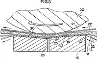
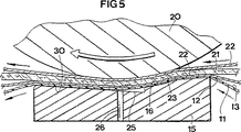
本発明の幾つかの利点は、プレスシュー15の外面16の形態にある。図6及び図7で最も良く分かるように、プレスシュー15の面16は、拡張ニッププレス10の上流端で向い合う凸面プレス要素20に対抗して可撓性ジャケット11と係合する侵入陸面23を含む。図6の実施形態では、侵入陸面23は平面であるのに対して、図7の実施形態では、侵入陸面は、全体的に凹面であり、凸面プレス要素20の曲率半径に対応した曲率半径を有する。凹面侵入陸面は長い流体力学の潤滑領域を生じさせるが、熱の大部分は以下に説明する下流の潤滑領域で発生するので、過度の熱発生の問題はない。
【0023】
侵入陸面23のすぐ下流は潤滑ポケット24である。潤滑ポケット24は、可撓性ジャケット11と共に流体静力学の潤滑領域を生じさせる潤滑剤の溜りを保持するキャビティを構成する。ポケット24は下流方向に可撓性ジャケット11の方に向かって収斂する底面25を有する。従って、ポケット24の深さは、深さが縦方向に減少する。これはポケット24の流体静力学の潤滑領域からの滑らかな移行をもたらす。図2及び図4に示すように、いくつかの潤滑ポケット24を並べて配置し、横方向に亘るようにしても良い。
【0024】
潤滑剤供給導管26が潤滑剤を潤滑剤供給源27からポケット24へ差し向ける。図面に示す実施形態では、潤滑剤供給導管26はシュー15の底面25に通じているが、侵入陸面23と底面25との間の段に通じさせることもできる。
逃げ陸面30が潤滑ポケット24から下流へ延び、拡張ニッププレス10の下流端で向い合う凸面プレス要素20に対抗して、可撓性ジャケット11と係合する。有利には、逃げ陸面30は凸面プレス要素20の曲率半径よりも大きな曲率半径を有する。詳細には、逃げ陸面30は図3及び図5に示すように平面である。ポケット24の平面の底面25は、逃げ陸面30と共通面であっても良いし、ジャケット11に面する175乃至179度の狭角(included angle)を構成するように逃げ陸面に対して1乃至5度傾斜しても良い。
【0025】
逃げ陸面30は凸面プレス要素20と相互適合する凹面−凸面関係ではないので、圧力ポケット24の下流に流体力学の潤滑の領域はほとんどできない。逃げ陸面30はカウンタープレス要素20よりも大きい曲率半径を有するので、逃げ陸面とカウンタープレス要素とは、繊維状ウェブ21、フェルト22及びジャケット11を取り除いたならば、線接触のみで係合する。換言すれば、本発明の縦方向の係合の長さは、イルマリネンの米国特許第5,262,011号に示されるような逃げ陸面及びカウンタープレス要素が実質的に等しい曲率半径(ウェブ、フェルト及びジャケットの有限の厚さに起因する少しの相違を除く)を有する従来の設計よりも短い。
【0026】
従って、プレスシュー15と凸面プレス要素20との間の、凸面プレス要素のほんの下流に小さい隙間があるので、流体力学の潤滑(及び熱の発生)は潤滑圧力ポケット(流体静力学の潤滑ポケット)のすぐ下流の小さい領域で起る。しかしながら、この領域は(凸面プレス要素20がプレスシュー15から離れるように急激に湾曲するので)小さく、従来の拡張ニッププレスと比較して、ほんの僅かしか摩擦熱が発生しない。本発明が、摩擦熱を除去するというよりもむしろ、摩擦熱を減じるということは理解されるべきである。
【0027】
逃げ陸面30が凸面プレス要素20と凹面−凸面相互適合関係を形成せず、かつ拡張した下流の流体力学の領域を回避する任意の輪郭のものである場合でも、本発明の利点は一般的に実現することができることも理解すべきである。例えば、逃げ陸面30は凹面であっても良いが、凸面プレス要素20よりも大きな曲率半径を有する。逃げ陸面30は又、図示した平面形態のような非凹面にするのが良く、凸面であっても良い。
【0028】
本発明の上記の特徴によって、拡張ニッププレス10は流体静力学のポケット24の下流に流体力学の潤滑の領域をほとんどもたない。その結果、プレスが高い直線荷重を与えられ、高い機械速度で運転されたとしても、拡張ニッププレス10の運転中、ほんの僅かの摩擦熱しか発生しない。従って、生産性の大きな改良が実現できる。
【0029】
以上の説明及び関連した図面によって与えられた教示の利益を有する本発明に関する本発明の多くの変更及び他の実施形態が当業者には思い付くだろう。従って、本発明は開示された特定の実施形態に限定されず、かつ変更及び他の実施形態を請求の範囲の範囲内に含むことを意図していることは理解されるべきである。ここでは特定の用語が採用されたが、それらは包括的かつ説明的な使用であり、限定目的のものではない。従って、拡張ニッププレスの記載は、脱水操作ばかりでなく、カレンダー(calendering)操作も含むことが意図されている。
【図面の簡単な説明】
【図1】 図1は拡張ニッププレスユニットの断面図である。
【図2】 図2は本発明による拡張ニッププレスシューの第1の実施形態の斜視図である。
【図3】 図3は図2のプレスシューの拡大断面図である。
【図4】 図4は本発明による拡張ニッププレスシューの第2の実施形態の斜視図である。
【図5】 図5は図4のプレスシューの拡大断面図である。
【図6】 図6はニッププレスに隣接したプレスの他の構成要素を指示しない、第1のニッププレスシューの拡大断面図である。
【図7】 図7はニッププレスに隣接したプレスの他の構成要素を指示しない、第2のニッププレスシューの拡大断面図である。[0001]
BACKGROUND OF THE INVENTION
The present invention relates to a papermaking machine, and more particularly to an extended nip press for removing water from a fibrous web as the fibrous web passes through the papermaking machine.
[0002]
[Prior art]
In papermaking technology, extended nip presses (also called long nip presses or wide nip presses) have a much larger dewatering capacity than that of conventional roll nip presses, so extended nip presses are very popular in the press section of papermaking machines. Has become more common. Today, extended nip presses marketed by a number of manufacturers are of the type typically referred to as shoe presses, but no other way to achieve an extended nip is known.
[0003]
[Problems to be solved by the invention]
A typical shoe press unit has a generally concave shoe, a rotatable flexible tubular jacket that runs in a loop around the shoe, a stationary support beam that supports the shoe, and an inner surface of the jacket. It has at least one (usually several) actuators provided on the support beam for pressing the shoe against, and a cylindrical counter roll. The shoe is often lubricated to avoid wear on the inner surface of the cylindrical jacket. The concave shoe and the cylindrical counter roll constitute an expanded nip between which the fibrous web is compressed.
[0004]
Compared to conventional roll presses, the main advantage of shoe presses is that higher linear loads can be used than in roll presses. The amount of dewatering that occurs at the press nip depends to a large extent on the compression impulse that can be calculated as I = L / S. Where I is the compression driving force, L is the linear load of compression (force per unit length in the cross machine direction), and S is the speed of the paper web through the nip. Theoretically, the compressive thrust is independent of the machine direction, i.e. the length of the nip in the direction in which the workpiece travels. However, the maximum linear load that can be applied at the press nip is limited by the pressure that the web can receive.
[0005]
In conventional roll presses, the nip area is very small, and even relatively low linear loads result in pressures that are clearly too high for the fibrous web through the nip. With a long nip, a shoe press with a large nip area can use very large linear loads and still does not reach the high level of nip pressure at which fibrous web crushing occurs. This is very important for papermakers who want to obtain large quantities of product. The shoe press can use a high linear load without applying high pressure to the fibrous web, so that a large amount of product can be obtained. Thus, the first commercial use of shoe presses is in machines for making large quantities of products, such as cardboard making machines. In recent years, shoe presses have been adopted for different grades of paper (paper grade).
[0006]
However, a high dewatering capacity is not always just a desired property of a press unit. For example, it may be desirable for the final product to have high strength due to Scott Bond. In order to obtain high strength paper with Scott Bond, the fibrous web should be subjected to high pressure as it passes through the press unit. A simple way to obtain high pressure in the nip is to use a conventional roll press unit. However, the roll nip does not meet the requirements for high dewatering capacity as described above. Moreover, the high pressure in the nip will result in an insufficient amount of product.
[0007]
Another solution is to use a shoe press and apply a higher than normal linear load. However, shoe presses are designed to provide a relatively low pressure and it is difficult to obtain very high pressure levels even with high linear loads. In addition, when the pressure level in the shoe press nip is increased, the frictional heat generated between the flexible jacket and the press shoe becomes a very serious problem even if the shoe is lubricated. The generated frictional heat causes shoe deformation and other problems associated with dissipating the generated heat, such as overheating of the flexible jacket. Frictional heat becomes particularly significant when the papermaking machine is operated at high speeds such as 25 m / s or higher.
[0008]
In order to solve the problem of frictional heat generated in the shoe press nip, US Pat. No. 4,643,802 (Schiel) suggests using a thermal insulation layer between the upper and lower portions of the shoe Has been. However, such a solution makes the shoe more complex and expensive to manufacture. Moreover, the use of a thermal insulation layer only prevents the heat from conducting to other parts of the machine and does not reduce the amount of heat transferred to the cylindrical jacket.
[0009]
The amount of frictional heat generated within the extended nip, nip pressure, machine speed, and depends on a number of parameters, such as lubricating device. For lubrication, a shoe press lubricating hydrodynamic (hydrodynamic Lubrication) is made, or can be lubricated hydrostatic (hydrostatic Lubrication) is made. In a hydrodynamically lubricated shoe, the lubricating oil can be applied between the flexible jacket of the shoe press and the front edge of the shoe itself, as disclosed, for example, in US Pat. No. 5,167,768 (Cronin et al.). It is better to spray on the boundary between. In a shoe that is hydrostatically lubricated , lubricating oil is sent through a conduit of the shoe to a lubrication pocket provided on the surface of the shoe. Such a lubrication device is disclosed, for example, in US Pat. No. 5,262,011 (Ilmarinen). Shoe lubrication hydrostatic is made has usually leading edge of at least hydrostatic lubrication, and / or, adjacent the trailing edge, also the area or zone of one or more hydrodynamic lubrication. The Ilmarinen patent discloses a leading and trailing land surface, both concave and having a radius of curvature corresponding to the radius of curvature of the counter roll, thereby providing hydrodynamic lubrication. And making a shoe that is hydrostatically lubricated .
[0010]
Most of the frictional heat in the shoe press nip is generated in the hydrodynamic lubrication zone. Thus, the problem of frictional heat can theoretically be overcome by using a shoe that is fully hydrostatically lubricated . It is suggested, for example, in German Patent DE 35 03 819 of Sulzer Escher-Wyss GmbH, which totally eliminated hydrodynamic lubrication. German patent DE 35 03 819 discloses a press shoe of the kind consisting almost entirely of hydrostatic pockets. Theoretically, such a shoe generates only a very small amount of frictional heat and can accommodate a high nip pressure combined with a high machine speed. However, the shoe disclosed in DE 35 03 819 has a sharp transition from the hydrostatic pocket to the end wall of the pocket. In the transition region, the flexible jacket will be stressed and worn and will generate a significant amount of heat.
[0011]
The inventor has discovered that fibrous webs made from wood-containing raw materials are insensitive to pressure and can be pressurized without significant loss of quantity. For such paper grades, such as super-finished paper (SC), or light coated paper (LWC), it is advantageous if the web is compressed in a high dewatering and high nip pressure press unit. The inventor has also recognized that this is best achieved if the web is compressed by a shoe press unit that employs a higher pressure than a conventional shoe press (but still lower than a roller press). However, if the conventional shoe press unit employs the high pressure required for the desired dewatering and Scott bond strength, excessive frictional heat generated within the press nip will be a problem.
[0012]
Accordingly, there is a need for a shoe press that can employ high nip pressure at high speeds to obtain the desired level of dewatering and Scott bond strength. However, such shoe presses must not overheat the shoe or jacket and must not have fast wear characteristics.
[0013]
[Means for Solving the Problems]
These and other objects and advantages are greater than the radius of curvature of the inrunning land surface, the lubrication pockets downstream of the intrusion land surface, and advantageously facing convex press elements such as counter rolls. Provided by a nip press shoe according to the present invention comprising an outrunning land surface downstream of the lubrication pocket having a large radius of curvature. In particular, the reduced hydrodynamic lubrication area with the flexible jacket is much smaller than the design of conventional press shoes with a concave relief surface with a radius of curvature substantially corresponding to the radius of curvature of the convex press element. As will occur, the run-off surface is advantageously a flat surface. For the narrowed hydrodynamic region, the amount of the frictional heat generated is considerably reduced, the machine can be operated at higher speeds, higher shoe pressures, thus improving productivity.
[0014]
An extended nip press is also provided by the present invention to dewater the fibrous web as it passes through the press in the machine direction. A flexible jacket having at least one impermeable surface is provided for pressing the fibrous web against a convex pressing element facing it, thereby dewatering the fibrous web. The flexible jacket is cylindrical and goes around a transversely extending support beam on the opposite side of the convex pressing element from the jacket. At least one actuator is supported by the support beam to generate a compressive force generally in the direction of the convex pressing element.
[0015]
The press shoe according to the invention is attached to an actuator and depresses the flexible jacket and the fibrous web against the convex pressing element to dehydrate the web. As described above, the shoe has a surface that includes an intrusive land surface for engaging the flexible jacket against the convex press element at the upstream end of the extended nip press. The intrusion land surface according to one embodiment is planar, creating a hydrodynamic lubrication region that narrows upstream of the hydrostatic lubrication pocket. According to another embodiment, the intrusion land surface is a concave surface that creates a slightly longer intrusion hydrodynamic region. The inventor has discovered that much of the frictional heat occurs in the downstream hydrodynamic region, and thus a slightly longer upstream hydrodynamic region does not diminish the preference of the present invention.
[0016]
Preferably, at least one lubrication pocket is provided downstream of the intrusion land surface and a plurality of separated pockets are arranged side by side in the lateral direction. Each lubrication pocket constitutes a cavity that holds the lubricant and, together with the flexible jacket, creates a hydrostatic lubrication region. Each pocket has a bottom surface that converges toward the flexible jacket in the downstream direction. In one embodiment, the bottom surface of the pocket is a plane.
[0017]
A run-off surface downstream of the lubrication pocket engages the flexible jacket against the convex press element at the downstream end of the expansion nip press. As noted above, the clearance surface advantageously has a positive radius of curvature that is greater than the radius of curvature of the convex press element, resulting in a hydrodynamic lubrication region that narrows with the flexible jacket. In one embodiment, the run-off surface is a flat surface and may be a common plane with the bottom surface of the lubrication pocket. In other embodiments, the escape surface is concave but has a larger radius of curvature than the convex press element. The escape surface may be convex. Such shoe has a bandwidth of lubrication of very short fluid dynamics downstream of the hydrostatic pocket, therefore, very little frictional heat downstream of the hydrostatic pocket only occur. Some of the objects and advantages have been described, other objects and advantages will become apparent when the description proceeds with reference to the accompanying drawings. The drawings are not drawn at a fixed ratio.
[0018]
DETAILED DESCRIPTION OF THE INVENTION
The present invention will now be described more fully hereinafter with reference to the drawings of preferred embodiments thereof. However, the present invention can be embodied in many different forms and should not be construed as limited to the embodiments set forth herein. Rather, these embodiments are provided so that this description will be thorough and complete, and will fully convey the scope of the invention to those skilled in the art. Like reference numerals refer to like elements throughout.
[0019]
With reference to FIG. 1, an extended nip press is shown. The
The
[0020]
At least one
[0021]
The
[0022]
Some advantages of the present invention are in the form of the
[0023]
Immediately downstream of the intruding
[0024]
A
[0025]
Since the
[0026]
Thus, there is a small gap between the
[0027]
The advantages of the present invention are general even when the
[0028]
Due to the above features of the present invention, the expanded nip
[0029]
Many modifications and other embodiments of the invention will occur to those skilled in the art having the benefit of the teachings provided by the foregoing description and the associated drawings. Therefore, it should be understood that the invention is not limited to the specific embodiments disclosed, and that modifications and other embodiments are intended to be included within the scope of the claims. Although specific terms have been employed herein, they are for comprehensive and descriptive use and are not intended to be limiting. Accordingly, the description of an extended nip press is intended to include not only a dewatering operation, but also a calendaring operation.
[Brief description of the drawings]
FIG. 1 is a cross-sectional view of an extended nip press unit.
FIG. 2 is a perspective view of a first embodiment of an extended nip press shoe according to the present invention.
FIG. 3 is an enlarged cross-sectional view of the press shoe of FIG.
FIG. 4 is a perspective view of a second embodiment of an extended nip press shoe according to the present invention.
FIG. 5 is an enlarged cross-sectional view of the press shoe of FIG.
FIG. 6 is an enlarged cross-sectional view of the first nip press shoe without indicating other components of the press adjacent to the nip press.
FIG. 7 is an enlarged cross-sectional view of a second nip press shoe that does not indicate other components of the press adjacent to the nip press.
Claims (16)
凸面プレス面を有する凸面プレス要素(20)と、
繊維状ウェブを前記プレス要素に対して押付け、それにより繊維状ウェブを脱水する少なくとも1つの不透水性面を有する可撓性ジャケット(11)と、
前記ジャケットに対して前記凸面プレス要素の反対側に設けられた、横方向に延びる支持ビーム(14)と、
概ね前記凸面プレス要素の方向に圧縮力を生じさせるために、前記支持ビームによって支持された少なくとも1つのアクチュエーター(17)と、
前記可撓性ジャケット及び繊維状ウェブを前記凸面プレス要素に対して押付けるために前記アクチュエーターに取り付けられたシュー(15)とを有しており、
前記シュー(15)は、
拡張ニッププレスの上流端で前記可撓性ジャケット(11)を前記凸面プレス要素(20)に押付けるための侵入陸面(23)と、
前記侵入陸面(23)の下流の少なくとも1つの潤滑ポケット(24)とを含む面(16)を有しており、前記潤滑ポケットが前記可撓性ジャケットと共に流体静力学の潤滑領域を生じさせるために潤滑剤を維持するキャビティを構成し、前記ポケットが下流方向に前記可撓性ジャケット(11)の方へ収斂する底面(25)を有しており、
前記面(16)は、更に、拡張ニッププレスの下流端で前記可撓性ジャケット(11)を前記凸面プレス要素(20)に押付けるための、前記潤滑ポケット(24)の下流の逃げ陸面(30)を含んでおり、
前記可撓性ジャケット(11)と共に流体力学の潤滑領域を生じさせるために、前記逃げ陸面(30)は、平面であるか、或いは、凸面である、
ことを特徴とする、拡張ニッププレス。An extended nip press (10) for dewatering the fibrous web as it passes through the press in the machine direction,
A convex pressing element (20) having a convex pressing surface;
A flexible jacket (11) having at least one impermeable surface for pressing a fibrous web against said pressing element, thereby dewatering the fibrous web;
A transversely extending support beam (14) provided on the opposite side of the convex pressing element to the jacket;
At least one actuator (17) supported by the support beam to generate a compressive force generally in the direction of the convex pressing element;
A shoe (15) attached to the actuator for pressing the flexible jacket and fibrous web against the convex pressing element;
The shoe (15)
Intrusion land surface for pressing the flexible jacket at the upstream end of the extended nip press (11) to said convex press element (20) and (23),
Having a surface (16) including at least one lubrication pocket (24) downstream of the intrusion land surface (23), the lubrication pocket creating a hydrostatic lubrication region with the flexible jacket. For forming a cavity for retaining the lubricant, the pocket having a bottom surface (25) converging in the downstream direction towards the flexible jacket (11),
Said face (16) is further for pressing the flexible jacket at the downstream end of the extended nip press (11) to said convex press element (20), downstream of the relief land surface of the lubricating pocket (24) (30)
In order to create a hydrodynamic lubrication region with the flexible jacket (11) , the escape surface (30) is flat or convex.
An extended nip press characterized by that.
拡張ニッププレスの上流端で可撓性ジャケット(11)を向い合う凸面プレス要素に押付けるための侵入陸面(23)と、
前記侵入陸面(23)の下流の少なくとも1つの潤滑ポケット(24)とを含む面(16)を有しており、前記潤滑ポケットが可撓性ジャケットと共に流体静力学の潤滑領域を生じさせるために潤滑剤を維持するキャビティを構成し、前記ポケットが下流方向に前記可撓性ジャケット(11)の方へ収斂する底面(25)を有しており、
前記面(16)は、更に、拡張ニッププレスの下流端で可撓性ジャケット(11)を向い合う凸面プレス要素(20)に押付けるための、前記潤滑ポケット(24)の下流の逃げ陸面(30)を含んでおり、
前記可撓性ジャケット(11)と共に流体力学の潤滑領域を生じさせるために、前記逃げ陸面(30)は、平面であるか、或いは、凸面である、
ことを特徴とする、拡張ニッププレスシュー。A extended nip press shoe for pressing the flexible jacket (11) facing the convex press element which moves in the longitudinal direction (20),
Intrusion land surface for pressing the convex press element facing the flexible jacket (11) at the upstream end of the extended nip press (23),
A surface (16) including at least one lubrication pocket (24) downstream of the intrusion land surface (23), the lubrication pocket together with a flexible jacket creating a hydrostatic lubrication region And a bottom surface (25) for converging in the downstream direction toward the flexible jacket (11),
It said face (16) is further for pressing the convex press element (20) facing the flexible jacket (11) at the downstream end of the extended nip press, the downstream flank land surface of the lubricating pocket (24) (30)
In order to create a hydrodynamic lubrication region with the flexible jacket (11) , the escape surface (30) is flat or convex.
An extended nip press shoe.
Applications Claiming Priority (3)
| Application Number | Priority Date | Filing Date | Title |
|---|---|---|---|
| SE9703766A SE511203C2 (en) | 1997-10-14 | 1997-10-14 | Long nip press and long nip press shoes for the same |
| SE9703766-7 | 1997-10-14 | ||
| PCT/IB1998/001612 WO1999019562A1 (en) | 1997-10-14 | 1998-10-13 | An extended nip press |
Publications (3)
| Publication Number | Publication Date |
|---|---|
| JP2001520330A JP2001520330A (en) | 2001-10-30 |
| JP2001520330A5 JP2001520330A5 (en) | 2009-03-05 |
| JP4278298B2 true JP4278298B2 (en) | 2009-06-10 |
Family
ID=20408629
Family Applications (1)
| Application Number | Title | Priority Date | Filing Date |
|---|---|---|---|
| JP2000516105A Expired - Fee Related JP4278298B2 (en) | 1997-10-14 | 1998-10-13 | Extended nip press |
Country Status (7)
| Country | Link |
|---|---|
| US (1) | US5997695A (en) |
| EP (1) | EP1060307B1 (en) |
| JP (1) | JP4278298B2 (en) |
| AT (1) | ATE266765T1 (en) |
| DE (1) | DE69823883T2 (en) |
| SE (1) | SE511203C2 (en) |
| WO (1) | WO1999019562A1 (en) |
Families Citing this family (15)
| Publication number | Priority date | Publication date | Assignee | Title |
|---|---|---|---|---|
| US6139691A (en) * | 1997-09-30 | 2000-10-31 | Valmet-Karlstad Ab | Shoe press |
| SE516706C2 (en) * | 1998-12-07 | 2002-02-12 | Metso Paper Karlstad Ab | Shoe press in a wire section of a cardboard or paper machine as well as a wire section |
| US6558510B1 (en) | 2000-08-21 | 2003-05-06 | Fort James Corporation | Wet-crepe process utilizing narrow crepe shelf for making absorbent sheet |
| DE10042906A1 (en) * | 2000-08-31 | 2002-03-14 | Voith Paper Patent Gmbh | Press arrangement |
| FI116405B (en) * | 2001-04-02 | 2005-11-15 | Metso Paper Inc | Arrangement for profiling a fibrous web |
| JP3875898B2 (en) * | 2002-02-06 | 2007-01-31 | イチカワ株式会社 | Shoe press device for paper machine |
| SE527236C2 (en) * | 2004-05-26 | 2006-01-24 | Metso Paper Karlstad Ab | Press, method at a press and press elements for a press |
| JP2013535786A (en) | 2010-07-29 | 2013-09-12 | フェデラル−モーグル・イグニション・カンパニー | Electrode material for use with spark plugs |
| US8471451B2 (en) | 2011-01-05 | 2013-06-25 | Federal-Mogul Ignition Company | Ruthenium-based electrode material for a spark plug |
| WO2012102994A2 (en) | 2011-01-27 | 2012-08-02 | Federal-Mogul Ignition Company | Electrode material for a spark plug |
| DE112012000947B4 (en) | 2011-02-22 | 2018-03-22 | Federal-Mogul Ignition Company | Method for producing an electrode material for a spark plug |
| DE112012002699B4 (en) | 2011-06-28 | 2018-12-13 | Federal-Mogul Ignition Company | Spark plug and method of manufacturing an electrode of a spark plug |
| US10044172B2 (en) | 2012-04-27 | 2018-08-07 | Federal-Mogul Ignition Company | Electrode for spark plug comprising ruthenium-based material |
| US8890399B2 (en) | 2012-05-22 | 2014-11-18 | Federal-Mogul Ignition Company | Method of making ruthenium-based material for spark plug electrode |
| US8979606B2 (en) | 2012-06-26 | 2015-03-17 | Federal-Mogul Ignition Company | Method of manufacturing a ruthenium-based spark plug electrode material into a desired form and a ruthenium-based material for use in a spark plug |
Family Cites Families (15)
| Publication number | Priority date | Publication date | Assignee | Title |
|---|---|---|---|---|
| US4427492A (en) * | 1981-05-26 | 1984-01-24 | Beloit Corporation | Extended nip shoe for a nip in a papermaking machine |
| FI71979B (en) * | 1981-06-24 | 1986-11-28 | Escher Wyss Ag | PRESSVALS |
| FI70272C (en) * | 1982-06-14 | 1986-09-15 | Tampella Oy Ab | LAONGZONSPRESS FOER PAPER MACHINE |
| FI76608C (en) * | 1982-07-13 | 1988-11-10 | Ahlstroem Valmet | Long nip press |
| DE3408118A1 (en) * | 1984-02-06 | 1985-08-14 | Sulzer-Escher Wyss GmbH, 7980 Ravensburg | WET PRESS FOR DRAINING A FIBER TRAIN |
| DE3503819A1 (en) * | 1984-12-21 | 1986-06-26 | Sulzer-Escher Wyss GmbH, 7980 Ravensburg | Hydraulic press shoe and its use and operation |
| DE3503240A1 (en) * | 1985-01-31 | 1986-08-07 | J.M. Voith Gmbh, 7920 Heidenheim | WET PRESS FOR DRAINING A FIBER TRAIN |
| US5167768A (en) * | 1991-11-07 | 1992-12-01 | Beloit Corporation | Wide nip web press and method using a press shoe with two pivots |
| SE469600B (en) * | 1991-12-23 | 1993-08-02 | Valmet Karlstad Ab | pressure shoe |
| FI94267C (en) * | 1992-12-30 | 1995-08-10 | Valmet Paper Machinery Inc | Long nip press shoe |
| US5441604A (en) * | 1994-02-17 | 1995-08-15 | Beloit Technologies, Inc. | Extended nip press apparatus |
| DE4409316C1 (en) * | 1994-03-18 | 1995-06-29 | Escher Wyss Gmbh | Long gap press assembly for fibre web |
| DE4415645A1 (en) * | 1994-05-04 | 1995-11-09 | Voith Sulzer Papiermasch Gmbh | Bending roller for a papermaking machine |
| DE29521610U1 (en) * | 1995-03-09 | 1997-11-20 | Voith Sulzer Finishing Gmbh | Calender for the treatment of a paper web |
| DE19544979B4 (en) * | 1995-12-01 | 2006-08-03 | Voith Paper Patent Gmbh | Device for compressing, smoothing and / or dewatering a fibrous web |
-
1997
- 1997-10-14 SE SE9703766A patent/SE511203C2/en not_active IP Right Cessation
- 1997-12-19 US US08/994,398 patent/US5997695A/en not_active Expired - Fee Related
-
1998
- 1998-10-13 DE DE69823883T patent/DE69823883T2/en not_active Expired - Lifetime
- 1998-10-13 EP EP98945504A patent/EP1060307B1/en not_active Expired - Lifetime
- 1998-10-13 JP JP2000516105A patent/JP4278298B2/en not_active Expired - Fee Related
- 1998-10-13 AT AT98945504T patent/ATE266765T1/en active
- 1998-10-13 WO PCT/IB1998/001612 patent/WO1999019562A1/en active IP Right Grant
Also Published As
| Publication number | Publication date |
|---|---|
| SE511203C2 (en) | 1999-08-23 |
| JP2001520330A (en) | 2001-10-30 |
| SE9703766D0 (en) | 1997-10-14 |
| DE69823883T2 (en) | 2005-05-19 |
| EP1060307A1 (en) | 2000-12-20 |
| SE9703766L (en) | 1999-04-15 |
| US5997695A (en) | 1999-12-07 |
| ATE266765T1 (en) | 2004-05-15 |
| EP1060307B1 (en) | 2004-05-12 |
| WO1999019562A1 (en) | 1999-04-22 |
| DE69823883D1 (en) | 2004-06-17 |
Similar Documents
| Publication | Publication Date | Title |
|---|---|---|
| JP4278298B2 (en) | Extended nip press | |
| US4576682A (en) | Long-nip press for a paper making machine | |
| US5626723A (en) | Surface contoured press jacket for a shoe press | |
| CA2032785C (en) | A press with extended press zone in a paper machine | |
| US3783097A (en) | Hydrodynamically loaded web press with slipper bearing shoes | |
| US5167768A (en) | Wide nip web press and method using a press shoe with two pivots | |
| EP0718434B1 (en) | Press section of paper machine, in particular for printing paper qualities | |
| CA1166499A (en) | Extended nip shoe | |
| EP0239570A1 (en) | A bearing blanket for an extended nip press. | |
| JP2001520330A5 (en) | ||
| US6197156B1 (en) | Press section of a paper machine, in particular for printing paper qualities | |
| JP4602344B2 (en) | Support body, holding device for the support body, apparatus for processing a web equipped with such a body, method of forming an extended nip in the apparatus, and method of controlling the load at the nip | |
| JP2752790B2 (en) | Press shoe | |
| US6083349A (en) | Machine and method for manufacturing a creped fibrous pulp web, with a shoe pre-press and a main shoe press | |
| JP4779564B2 (en) | Shoe press apparatus for paper machine and paper manufacturing method | |
| CA1235012A (en) | Extended nip press | |
| EP1373636B1 (en) | Arrangement for profiling a fibre web | |
| WO2000019010A1 (en) | Lubricating arrangement and method when impulse-pressing a fibre web | |
| CA2338244A1 (en) | A long nip press | |
| US20020053415A1 (en) | Shoe press | |
| WO2022048877A1 (en) | Shoe press for paper and related method | |
| WO2008046960A1 (en) | Pressing arrangement in the processing apparatus of a paper/board machine or finishing machine with a metal belt loop | |
| WO2008068381A1 (en) | Loading element for a fibre-web machine | |
| WO2001051704A1 (en) | Method for pressing a paper web and a press device for a paper web |
Legal Events
| Date | Code | Title | Description |
|---|---|---|---|
| A621 | Written request for application examination |
Free format text: JAPANESE INTERMEDIATE CODE: A621 Effective date: 20050811 |
|
| A977 | Report on retrieval |
Free format text: JAPANESE INTERMEDIATE CODE: A971007 Effective date: 20080428 |
|
| A131 | Notification of reasons for refusal |
Free format text: JAPANESE INTERMEDIATE CODE: A131 Effective date: 20080507 |
|
| A521 | Request for written amendment filed |
Free format text: JAPANESE INTERMEDIATE CODE: A523 Effective date: 20080806 |
|
| A131 | Notification of reasons for refusal |
Free format text: JAPANESE INTERMEDIATE CODE: A131 Effective date: 20080922 |
|
| A524 | Written submission of copy of amendment under article 19 pct |
Free format text: JAPANESE INTERMEDIATE CODE: A524 Effective date: 20081222 |
|
| TRDD | Decision of grant or rejection written | ||
| A01 | Written decision to grant a patent or to grant a registration (utility model) |
Free format text: JAPANESE INTERMEDIATE CODE: A01 Effective date: 20090216 |
|
| A01 | Written decision to grant a patent or to grant a registration (utility model) |
Free format text: JAPANESE INTERMEDIATE CODE: A01 |
|
| A61 | First payment of annual fees (during grant procedure) |
Free format text: JAPANESE INTERMEDIATE CODE: A61 Effective date: 20090310 |
|
| FPAY | Renewal fee payment (event date is renewal date of database) |
Free format text: PAYMENT UNTIL: 20120319 Year of fee payment: 3 |
|
| R150 | Certificate of patent or registration of utility model |
Free format text: JAPANESE INTERMEDIATE CODE: R150 |
|
| LAPS | Cancellation because of no payment of annual fees |