JP4276704B2 - Virtual environment viewpoint control - Google Patents
Virtual environment viewpoint control Download PDFInfo
- Publication number
- JP4276704B2 JP4276704B2 JP53588999A JP53588999A JP4276704B2 JP 4276704 B2 JP4276704 B2 JP 4276704B2 JP 53588999 A JP53588999 A JP 53588999A JP 53588999 A JP53588999 A JP 53588999A JP 4276704 B2 JP4276704 B2 JP 4276704B2
- Authority
- JP
- Japan
- Prior art keywords
- user
- virtual environment
- zone
- cursor
- character
- Prior art date
- Legal status (The legal status is an assumption and is not a legal conclusion. Google has not performed a legal analysis and makes no representation as to the accuracy of the status listed.)
- Expired - Fee Related
Links
Images


Classifications
-
- A—HUMAN NECESSITIES
- A63—SPORTS; GAMES; AMUSEMENTS
- A63F—CARD, BOARD, OR ROULETTE GAMES; INDOOR GAMES USING SMALL MOVING PLAYING BODIES; VIDEO GAMES; GAMES NOT OTHERWISE PROVIDED FOR
- A63F13/00—Video games, i.e. games using an electronically generated display having two or more dimensions
- A63F13/50—Controlling the output signals based on the game progress
- A63F13/52—Controlling the output signals based on the game progress involving aspects of the displayed game scene
- A63F13/525—Changing parameters of virtual cameras
- A63F13/5258—Changing parameters of virtual cameras by dynamically adapting the position of the virtual camera to keep a game object or game character in its viewing frustum, e.g. for tracking a character or a ball
-
- A63F13/12—
-
- A—HUMAN NECESSITIES
- A63—SPORTS; GAMES; AMUSEMENTS
- A63F—CARD, BOARD, OR ROULETTE GAMES; INDOOR GAMES USING SMALL MOVING PLAYING BODIES; VIDEO GAMES; GAMES NOT OTHERWISE PROVIDED FOR
- A63F13/00—Video games, i.e. games using an electronically generated display having two or more dimensions
- A63F13/30—Interconnection arrangements between game servers and game devices; Interconnection arrangements between game devices; Interconnection arrangements between game servers
-
- G—PHYSICS
- G06—COMPUTING; CALCULATING OR COUNTING
- G06F—ELECTRIC DIGITAL DATA PROCESSING
- G06F16/00—Information retrieval; Database structures therefor; File system structures therefor
- G06F16/40—Information retrieval; Database structures therefor; File system structures therefor of multimedia data, e.g. slideshows comprising image and additional audio data
-
- A—HUMAN NECESSITIES
- A63—SPORTS; GAMES; AMUSEMENTS
- A63F—CARD, BOARD, OR ROULETTE GAMES; INDOOR GAMES USING SMALL MOVING PLAYING BODIES; VIDEO GAMES; GAMES NOT OTHERWISE PROVIDED FOR
- A63F2300/00—Features of games using an electronically generated display having two or more dimensions, e.g. on a television screen, showing representations related to the game
- A63F2300/40—Features of games using an electronically generated display having two or more dimensions, e.g. on a television screen, showing representations related to the game characterised by details of platform network
- A63F2300/407—Data transfer via internet
-
- A—HUMAN NECESSITIES
- A63—SPORTS; GAMES; AMUSEMENTS
- A63F—CARD, BOARD, OR ROULETTE GAMES; INDOOR GAMES USING SMALL MOVING PLAYING BODIES; VIDEO GAMES; GAMES NOT OTHERWISE PROVIDED FOR
- A63F2300/00—Features of games using an electronically generated display having two or more dimensions, e.g. on a television screen, showing representations related to the game
- A63F2300/50—Features of games using an electronically generated display having two or more dimensions, e.g. on a television screen, showing representations related to the game characterized by details of game servers
-
- A—HUMAN NECESSITIES
- A63—SPORTS; GAMES; AMUSEMENTS
- A63F—CARD, BOARD, OR ROULETTE GAMES; INDOOR GAMES USING SMALL MOVING PLAYING BODIES; VIDEO GAMES; GAMES NOT OTHERWISE PROVIDED FOR
- A63F2300/00—Features of games using an electronically generated display having two or more dimensions, e.g. on a television screen, showing representations related to the game
- A63F2300/60—Methods for processing data by generating or executing the game program
- A63F2300/66—Methods for processing data by generating or executing the game program for rendering three dimensional images
- A63F2300/6653—Methods for processing data by generating or executing the game program for rendering three dimensional images for altering the visibility of an object, e.g. preventing the occlusion of an object, partially hiding an object
-
- A—HUMAN NECESSITIES
- A63—SPORTS; GAMES; AMUSEMENTS
- A63F—CARD, BOARD, OR ROULETTE GAMES; INDOOR GAMES USING SMALL MOVING PLAYING BODIES; VIDEO GAMES; GAMES NOT OTHERWISE PROVIDED FOR
- A63F2300/00—Features of games using an electronically generated display having two or more dimensions, e.g. on a television screen, showing representations related to the game
- A63F2300/60—Methods for processing data by generating or executing the game program
- A63F2300/66—Methods for processing data by generating or executing the game program for rendering three dimensional images
- A63F2300/6661—Methods for processing data by generating or executing the game program for rendering three dimensional images for changing the position of the virtual camera
- A63F2300/6684—Methods for processing data by generating or executing the game program for rendering three dimensional images for changing the position of the virtual camera by dynamically adapting its position to keep a game object in its viewing frustrum, e.g. for tracking a character or a ball
-
- A—HUMAN NECESSITIES
- A63—SPORTS; GAMES; AMUSEMENTS
- A63F—CARD, BOARD, OR ROULETTE GAMES; INDOOR GAMES USING SMALL MOVING PLAYING BODIES; VIDEO GAMES; GAMES NOT OTHERWISE PROVIDED FOR
- A63F2300/00—Features of games using an electronically generated display having two or more dimensions, e.g. on a television screen, showing representations related to the game
- A63F2300/80—Features of games using an electronically generated display having two or more dimensions, e.g. on a television screen, showing representations related to the game specially adapted for executing a specific type of game
- A63F2300/8082—Virtual reality
Description
技術分野
本発明は、ユーザのコンピュータが発生させる仮想存在が現れ、そして同様な他のユーザの仮想存在と、さらにオプションとして環境それ自身の特徴と、対話できる仮想世界の視点を、一人また複数のユーザに提供する熱中できるゲームおよび仮想現実または共有仮想(マルチユーザ)仮想環境システムのような対話型環境システムに関する。本発明は、特に、(ユーザに提供される)環境のイメージの視点を制御可能に変化させる手段を有するこのようなシステムに関する。(以下、この特徴を「仮想カメラ」制御と称する。)
背景技術
遠隔のユーザが、アクセスできる仮想環境(またはサイバースペース)を提供しているシステムは、ヨーロッパ特許出願EP-A-0 697 613(ソニー(株))に記載されている。ここに記載されているシステムは、仮想現実スペースを提供するサーバーと、(オプティカルファイバー等を使用した)高速通信ネットワークを介してサーバーに接続されているユーザ端末とを含む。動作中、サーバーは、数多くの仮想環境を維持し、そして情報オブジェクトとユーザオブジェクトとの間の変換オブジェクトの使用によって、多くの異なった端末タイプをサポートする。ここで、変換オブジェクトは、端末の各タイプとサポートされる仮想環境の各構成との間の相互通信に専用の翻訳を個別に提供する。
各ユーザ端末で、ユーザには、その時点で見ているユーザと同じ仮想環境の領域にいる他の全てのユーザのコンピュータ生成の表示と共に、三次元の環境内でそれら自身の特定の視点位置から見る三次元の仮想環境の二次元の視点が与えられる。そのユーザが見ているイメージ内の見ているユーザの全部または一部を表示させるよりはむしろ、EP-A-0 697 613のシステムは、第一人称の視点(すなわち、そのイメージが、ユーザのコンピュータが発生するキャラクタの「目」を通して見るイメージ)をとる。そして、このシステムは、提供された環境の二次元のイメージ内でのカーソルの上下左右の動きによって、または2人のユーザ間の会話または他の対話を開始するために、別のユーザの仮想キャラクタをクリックすることによって、ユーザが、仮想環境内から項目を示すまたは選ぶために利用できる単純な矢形のカーソルを提供する。このテクニックは、EP-A-0 697 613の場合、ユーザに表示されるキャラクタが、ユーザに提示されるイメージの中心に常に現れる従来技術システムに対する改良として、ユーザが、仮想環境内でそれらの表示を第三者の視点で見ることが出来るように使用されている。
第一人称の視点による描画は、ユーザが仮想環境内に浸る感覚を強化することにはなるが、第三者の視点が対話のためのコンテキストでより多くの情報をユーザに提供する、他のユーザの仮想表示と対話する場合には、第一人称の視点による描画は、満足行くものではないことが判る。自分自身の表示に関する視点(仮想カメラの位置)を選ぶことが出来ることは、利点ではあるが、毎回視点を選択しなければならないことは面倒なことである。
発明の開示
本発明の目的は、例えば、とりわけ、ユーザの仮想存在と他のユーザの表示との間の対話が行われているか否かに応じて、適切な視点を提供するために、自動的に仮想カメラの位置を調整するように構成されているシステムを提供することである。本発明の第一態様に従うマルチユーザ対話型仮想環境システムは、仮想環境を規定しているデータを含んでいる第一データ記憶部と、複数のキャラクタの外観を規定しているデータを含んでいる第二データ記憶部と、複数の別々のユーザから入力命令を受信するために結合されていて、前記第一および第二の記憶部にアクセスするように構成され、そして各々のユーザに対し前記仮想環境とそこの有るキャラクタの各イメージを生成する、プロセッサとを有し、前記ユーザが割り当てたキャラクタのユーザが指示した動きによって、少なくとも部分的に決定される前記仮想環境内の位置およびオリエンテーションでの各視点から、その個々のユーザに固有の割り当てられたキャラクタを含む、マルチユーザ対話型仮想環境システムにおいて、対話ゾーン生成手段が、各キャラクタに対する現在の仮想環境位置についての既定のサイズおよび形状の各ゾーンに対して、アップデートされた座標を維持するように構成されていて、そして、モニター手段が、前記ゾーン生成手段に結合されていて、かついつ、2つ以上のユーザが割り当てたキャラクタの各対話ゾーンが重なり、かつそれを当該プロセッサに合図するかを決定するように構成されていて、このような各ユーザが割り当てたキャラクタに対する各視点位置およびオリエンテーションの決定が、前記重なりが有る限り、前記プロセッサにより適用される既定の組のルールに少なくとも部分的に基づいていることを特徴とする。
ユーザの仮想カメラ位置を切替えるために、対話ゾーン(これは、ユーザには見えないのが好ましい)によるトリガメカニズムが設けられている。例にて後述されるように、対話がない(ゾーン重複がない)場合、仮想カメラは、「その肩越しに」効果的に見通せる位置でそのキャラクタに単に追随するのみであるが、対話がある場合、2つの対話している表示のより有益な視点を与えるために第三者の視点に移行する。
複雑なユーザ仮想存在を実行するために利用できるパワーが増加するにつれて、仮想世界の同じ部分を同時に訪問できるユーザの数は増大するので、仮想存在が組み入れられる仮想世界のサイズおよび/または複雑さは増大する。この結果、小さい領域で大規模な重なりが発生し、カメラの位置を計算する際、プロセッサに容認できない負荷が掛かることがある。この潜在的な問題を避けるために、プロセッサは、仮想環境内のいかなる特定キャラクタからも独立している、少なくとも一つの別の対話ゾーンを、仮想環境内の固定位置で適切に維持する。仮想環境内の人気があるおよび/または混雑した位置にこれらの固定されたゾーンを設けると、個々にカメラ位置を計算すること無く、カメラ位置を決定している規則の特定の組により、その領域をカバーしているグローバルカメラの視点を、その領域の中の全てのキャラクタに対して指定することが出来る。この特徴は、仮想環境内の特定の位置に対し(その位置のキャラクタ/カーソルの数に関係なく)前もって設定させておくことができるし、または、例えば、5つ以上のキャラクタの対話ゾーンが重ねっていると決定された位置には動的に適用させることもできる。
改良例の場合、キャラクタ対話ゾーンが外側の部分的なゾーンのみと重るときには、これらの固定された対話ゾーンを、プロセッサにより適用されている規則の組の一部のみを有する少なくとも2つの部分的なゾーンの同心の配列から形成することができる。換言すれば、各キャラクタのカメラの動きの程度は、(グローバルなカメラ位置決めを有する)内側の部分的なゾーンに接近する際のキャラクタの動きの減少により決定される。
本発明の他の特徴および効果は、添付の図面を参照して、例としてのみ記載されている本発明の好適な実施例の以下の記述から明らかになるであろう。
【図面の簡単な説明】
第1図は、本発明の態様を具体化するユーザ端末の構成に適しているデータ処理装置のブロック略図である。
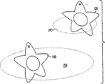
第2図は、星型のユーザ表示またはカーソルの肩越しに仮想環境のユーザ視点を表す。
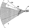
第3図は、第2図のカーソルの指示されたアテンションが強調表示されている視線-コーンを示す。
第4図は、カーソルおよび仮想カメラの1つの可能な相対位置、およびカメラ視点のスクリーンフィールドの分割を示す。
第5図は、仮想カメラがカーソルの回転運動を追跡するテクニックを示す。
第6図は、静止しているカーソルと動いているカーソルのスクリーン上のディスプレイ位置の相違を示す。
第7図は、それぞれ対話ゾーンを有する一対のカーソルを示す。
第8図は、第7図の一対の対話ゾーンの重なりを表す。
第9図は、カーソルの外側の多くの離散的なゾーンへの名目分割を示す。
第10および11図は、視線コーンによって、対話を始める一対のカーソルを示す。
第12〜15図は、2つおよび3つのカーソル対話に対する仮想カメラの動きを示す。
第16図は、2つまたは3つの個別のグループ内で対話している仮想環境内の複数のカーソルを表す。
第17図は、対話しているカーソルのより大きなカーソルを提供する固定された対話ゾーンを示す。
発明を実施するための最良の形態
第1図は、仮想環境を規定しているデータのブラウザとしてそれを構成するソフトウェアユーティリティに対するホストとして機能する、ユーザデータ処理システム2(例えば、パソコン)を含むネットワーク仮想環境システムを示す。データは、ネットワーク8の接続を介して遠隔のソース4と、ソース4に同様に接続されている類似したデータ処理システムを有する他のユーザ6とから得られる。。ユーザシステム2は、アドレスおよびデータバス12を介して、ランダムアクセス(RAM)とリードオンリーメモリ(ROM)装置14、16に、連結されている中央処理ユニット(CPU)10を有する。これらのメモリ装置の容量は、追加のメモリ装置、例えばCD-ROM(図示せず)から読み込む手段をシステムに加えることによって、増大させることが出来る。
また、キーボードおよびカーソル制御および選択装置(例えば、マウスまたはトラックボール)を適切に有することができる第一および第二のユーザ入力装置18、20が、バス12を介してCPU10に連結されている。システムからの音声出力は、音声処理段24により駆動されるヘッドホンまたは一つ以上のスピーカ22に与えられる。増幅することに加えて、この音声処理段は、CPU10の制御の下に既存の音声データにエコーのような音処理を加える信号の処理能力も与えるように、構成させることが好ましい。ユーザシステムの能力とソース4から供給されるデータのフォーマットとに応じて、システムからのビデオ出力は、ディスプレイドライバ段28により駆動される表示画面26上に一連の二次元イメージとして、または自動立体的な(autostereoscopic)ディスプレイまたは立体的なヘッドマウント式のディスプレイ(図示せず)上に一連の三次元イメージとして表示させることができる。
上述のごとく、システムのデータの別のソースは、仮想環境を規定しているデータの、ソースおよびそのデータのコントローラとして機能するサーバー4を含む、例えば、インターネットを介する、遠隔サイトへのオンラインリンクである。このために、システムには、バス12を介してCPU10に結合されているネットワークインタフェース30が設けられている。インタフェース構成は、システムが結合されるデータネットワーク8のタイプに依存する。例えば、システムが個人のホームユーザにより使用される場合、データリンクは、ローカルサービスプロバイダへの電話接続であろう。このような場合、インタフェース30には適切なモデムが組み込まれるであろう。しかしながら、インタフェースの厳密な構成は、本発明の重要な特徴ではない。他の種類のデータリンク(例えば、ISDN接続)に対しては、インタフェースはそれに対応させて設定される。
動作中、仮想環境のユーザの視点は、他の動き命令がない場合、コンピュータ生成のキャラクタまたはユーザの仮想存在を表しているカーソル100の後の位置(ほとんど第一人称の視点を提供する、その表示の僅か上または横にある(実質的に、その「肩」越しに見とおしている)位置)に在るものと仮定される仮想カメラにより生成される。以下の実施例では、ユーザのコンピュータが生成するキャラクタおよび同じ環境内の他のユーザのキャラクタは、ユーザに対する仮想存在として機能するのみならず、ユーザに、(他のユーザの)このようなカーソルのみならず、仮想環境内で提供することができる他の特徴およびオブジェクトとも対話する手段を提供するカーソルとして機能する、星型のシンボル形状である。これらのシンボルまたはキャラクタを、以下、カーソルと称する。
上述されかつ第2図に示されるように、カメラの基本的視点は、ユーザのオリエンテーションが判るように最低限の存在を保持して、ユーザに、仮想環境102の妨げられない視点を与える、カーソル100の「肩」越しの視点である。カメラ位置、ズーミングおよびレンズ選択のような他の効果は、UID(第1図の18、20)演算によって、ユーザがカメラを直接制御せずにカーソルの動き、動作およびプロフィール開示から、(後述するように)、自動的に決定される。
第3図に示されるように、カーソル100は、そのアテンションを指示する「視線コーン」104を有する。視線フィールドは、90°の角度でカーソルに設けけられていて、視線コーンの長軸106は、一般に平らなカーソルに対し垂直に延在すると言える。動作中、環境イメージを生成するグラフィックスは、環境に対する視線コーンの位置関係をユーザに表示し、そして、アテンションのカーソルポイントが直観的に判るように、それらの環境の特徴が視線コーン内でそれらの外部に比べてより詳細に現れるようにさせる。
仮想カメラからの視点(第1図のスクリーン26上でユーザに提示される視点)は、スクリーンフィールドに分割される。これらのフィールドは、ユーザには見えない。(後述するように)異なったスクリーンフィールド内の視線コーンの位置により、カメラの自動的な再位置決めが行われる。第4図は、異なったスクリーンフィールド(A.1、B.1、...E.5)に分割されている仮想カメラからの視点を示している指し込み図112を伴う、仮想カメラ110およびカーソル100の平面図である。視線のカーソル方向が、上下左右に移動すると、カメラ110は視線方向とともに動く。実際、カーソル100が、例えば、左の方へその視線を回し続けると、カメラおよびカーソルは、両方とも円上に進行し、最後に仮想環境の本来の部分が見える状態に戻る。第5図は、3つのステップ(A、B、C)において、視線コーンが回転することによって、中央スクリーンフィールド(この立面図の2、3および4)の外に移動したときに、カメラ110が、どのようにして、カーソル100がフォーカスしている方向(視線コーン長軸106)が再び描かれた視点方向を含むようにそれ自体を再配置させるかを示している。このようにカメラと視線コーンとを分離したことにより、ユーザによる動き制御の不安定な動作に対応したものであろうカーソルの小きざみの動きが、仮想カメラからのイメージに不安定な動きを発生させることなく、吸収される。
第6A図に示されるように、カーソル100の肩越しのフレーミングは、仮想環境内で静止しているカーソルの安定した位置を表す。カーソル100が移動すると、カメラ位置は、自動的に変わり、(例えば、ナビゲーション命令の基礎を形成するより大きい環境のコンテキストをユーザに提供するように)第三者の視点をより多く与える。静止しているカーソルの場合、カーソルの部分的に見える部分は、表示されたイメージの端に現れる。(第6B図の視点の矢印114により示される方向に)移動する際、カーソルの速度が速ければ速いほど、カーソルは、イメージの中心により近く現れる。視線コーンの方向を回転により移動させると、回転の方向およびその範囲によって決る傾きで、カーソルは第三者の視点(すなわちスクリーン内で完全に見えるカーソル)により表示される。
第7図に示されるように、異なったユーザのカーソル間の対話については、カーソル100は、アクションまたは対話のゾーンのサークル200を有し、そしてマルチユーザの環境では、各カーソル100,120は、それぞれ対話ゾーン200、220を有する。三次元の仮想環境の場合、カーソルを囲んでいるゾーンは、球形とするか、またはその量の大部分がカーソルの前部に配置される、一般に視線コーンの長軸(第3図の106)に整列されている卵形のように、一つ以上の方向に伸長された形状とすることができる。対話ゾーン200のサイズは、カーソル100が他のカーソルと対話するであろう範囲を決定する。何故ならば、対話ゾーンが第8図に示されるように合体または重なるとき、対話は、カーソルの対またはグループ間でのみ起こるからである。2つ以上の対話ゾーンの合体または重なりは、後述されるように、有効なゾーンの各カーソルに対するカメラ制御に影響を与える。
ユーザは、自分自身のプロフィール開示の個人の要素(異なったアクセス必要条件で入れ子にされた形式の情報を有するデータ構造)を作成したり、またはそれに影響を与えることができる。プロフィール開示の情報の量および種類は、好適な実施例の場合、対話ゾーンのサイズを決定することが出来る。例えば、そのプロフィール開示の外側の(公共の)レイヤに大量の情報を保持しているカーソルは、対話する可能性が大である(それゆえ、大きい対話ゾーンを有する)と考えられる。
カーソルのユーザプロフィール開示の情報は、カーソルユーザプロフィール情報が見えるようになるように視線コーン(その視線は、スキャンされたカーソルにより検出される)により他のカーソルの外側をスキャンすることにより、他のカーソルによってアクセスすることができる。第9図に示されるように、カーソルの外側は、ユーザの基本的詳細情報およびユーザの好みのようなプロフィール開示の公共のレイヤからのデータが、既定の配列で分布している多くのゾーン121-125に分割される。中心ゾーン126は、カーソルユーザのより個人的で私的なデータを有している。これらのゾーン(特に外側のゾーン121-125)は、より「敏感である」。すなわち、他のカーソルによるスキャンに応じて、他のゾーンよりもそれらの内容を与える用意がある。例えば、中心ゾーン126の個人的なデータは、自動的に与えることはできず、その代わりに、ユーザに明確な開錠を要求させおよび/またはそれが誰のカーソルであるかをユーザが送ることを要求させることが出来る。ゾーンの感度が、スキャンしているカーソルを追跡しているカメラにより適用されるズームの範囲を決定する。例えば、保持されているまたはスキャンされるゾーンの情報が、スキャンしているカーソルにより検索される情報の何れかに対応する場合、マッチしたことが確認されると、スキャンしているカーソルを追跡しているカメラはマッチした情報のソースにズームインするであろう。ズームを制御するための別の方法は、潜在的にスキャンされるカーソルがそのゾーンの特定の一つを潜在的にスキャンするカーソルに移動させ、ゾーンへのアプローチにより、カーソルカメラをズームインさせることである。
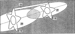
対話ゾーンが重ならない場合でも、カーソルは、視線コーンによって対話することが可能である。2つのカーソルが視線コーンを互いに向け合うと、一方向の通信チャネルが開かれる。一方向の通信チャネルにより、カーソルは、それらの公開ユーザプロフィールの開示から、データ(音部分、イメージ等)を送ることが可能となる。第10図は、他のカーソル上にそれらの各視線コーン104、134を有するが、それらの対話ゾーン200、230は分離されていて、一方向のチャネルのみがそれらの間に存在する一対のカーソル100、130を示す。2つのカーソルが互いに近づくにつれて、第11図に示されるように、それらの対話ゾーンは重なり、2つのカーソル100、130の間のリンクは一方向から双方向の通信リンク150に変換され、スキャンしているカーソルは、外側の公共のレイヤよりむしろスキャンされたカーソルのより深いプロフィールレイヤからデータを得ることができるようになる。
重なり合う対話ゾーンの機構は、更に第12〜15図に示されている。遭遇時のユーザ視点を作るカメラ位置は、合体された対話ゾーンにより規定される。両方のカーソルを示すいかなるカメラ位置も、第12図に示されかつ合体された対話ゾーンにより規定される領域160(この領域は180°スペースとして映画撮影技術から公知である)の半分の中に有る。カーソル100、130で描かれる何れのカメラ位置も、この180°スペースにより規定される。これの厳密な適用により、視点がカーソルの一方から他方に切替わるとき、これが適用されないときに起こる方向感覚が失われる効果を避けることが出来る。
合体された対話ゾーンから180°スペース160が規定され、次いでスペースは(ライン162の何れかの側で)2つの四半分に分割される。各カーソルからの仮想カメラは、各四半分内の位置しか取り上げることが出来ない。各カーソルは、そのカメラの位置決めに割り当てられている四半分の中に、それ自身のカメラ移動曲線を有する。第13図は、カーソル100に対する図の左にあるカメラ110の位置の概要を示す。カメラは、四半分の境界でスムーズに移動曲線を移動できる。移動曲線全体に渡り、カメラは、Cでの第三者の視点から、Bでのオフセット肩越しの視点を介して、Aでの第一人称の視点に移ることができる。ある実施例の場合、第一人称の視点において、それら自身のカーソルのユーザ視点を、対話しているカーソルの視点が不明瞭になることを避けるために描かれたイメージから消すことができることに留意すべきである。
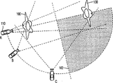
2つのカーソル100、130が出会うと、それらのカメラ移動曲線は、上述したように互いに対向するであろう。第14図に示されるように、180°スペースの外側の第3のカーソル170は、最初、他の2つのカーソルに対し何の効果も与えずに受動的である。しかしながら、第15図に示されるように、第3のカーソル170が第一のカーソル100または第二のカーソル130カーソルの何れかと対話すると、180°スペース160は、3つのカーソルからシフトして、対話している対100、170を取り囲み、(何れも、動いていなかったと仮定して)カーソル100、130の本来の対がそれらの対話を再び始めると、その本来の位置に戻る。
他のユーザとの(またはオプションとして仮想環境の他の特徴との)単純な遭遇に加えて、ユーザプロフィールの開示からマテリアルをまたはカーソルボディの「柔らかい」部分(第9図の中心ゾーン126)に含まれるより個人的な材料を交換することも、カメラ位置を移動させることになろう。大量の情報が2つのカーソルの間で転送されている場合、それらのそれぞれのカメラ位置を、徐々にまたは素早く第一人称のつまり肩越しの視点から第三者の視点まで移るように制御させることが出来る。1つのカーソルの受動性により、カメラの視点を変化させることもできる。双方向通信リンクが、一対のカーソルの間に存在するが、一方のカーソルのみが、データを送ることおよび/またはデータを読み込めるようにすることにアクティブである場合、受動的なカーソルを追跡しているカメラは、そのアクティブなカーソルにズームインするように適切に設定させることも出来よう。
仮想環境内に多くのカーソルがある場合、それらの各カメラ位置は、重なっている対話ゾーンおよび/または目的の視線コーンが存在するか否かを参照して、一般に上述のように制御されるであろう。しかしながら、実際的な条件では、処理により規定される同時に対話するカーソルの数と、システムが利用できる速度パワーには制限が有る。例えば、ゾーンを合体するために必要となる計算が、ユーザに受容出来なくなる状態までシステムを遅くしないように、同時に起こる重なり合う対話ゾーンの数を5つに制限することが出来る。しかしながら、第16図に示されるように、単一環境内では、合体されたカーソルの組および三つ組みのいくつかのグループは、適応させることができる。
ユーザが利用できる仮想環境が多くある場合、(それらのカーソルを介して)大量のユーザを引きつけ、そしてこのような領域が、あまりに多くのカーソルが一時に対話しようとして、「固まってしまう」ことのないように、ある種の緩和策が必要となるような環境は起こり得る。これは、カメラ制御を統治するそれら自身のプロトコルをこのような領域に設けることにより達成される。実際、この領域は、カーソルに取り付けられていない固定された対話ゾーンである。カメラ振付け、カット、ディゾルブ、リズム、色およびストロボの効果は、カーソルが領域の中のどの部分にいるかに応じて、自動的に割り当てることができる。第17図は、外側のゾーンCでの2つか3つのカーソル対話に対する上記したような完全制御から、視点生成が全ての含まれるカーソルに対し単一領域メカニズムにより取り扱われている個々の制御が無い内側のゾーンAの状態まで、各々のゾーンのカーソルに割り当てられる個々のカメラ制御のレベルを決定している、同心のゾーンA、B、Cがあるこのようなスペースを示す。ユーザの唯一の制御オプションは、領域の中心に残るかまたはそこから去るかである。
内側のゾーンAのユーザプロフィール情報の表示と交換の場合、プロトコルは、全てのカーソルがそれらの公共のレイヤ(それらの内部データ記憶構造の、アクセスがより容易な外側のレイヤ)から、適切に何らかの情報を「リークする」ようにさせる。そして、そのリークされた情報は、それが他のカーソルにとって重要な場合、その領域内の他のカーソルが拾うことができる。一旦情報が拾われると、それをリークしたカーソルは通知され、そして2つのカーソル302、304は、例えば、2つのカーソルの間の交換にある程度のプライバシーを与えるために、肩越しの視点描画での対話がサポートされている第一境界領域Bに移る。この交換に基づいて、2つのカーソルがより私的な詳細を交換することを望むと決定されると、それらは、ゾーンBを越えて、カーソル306および308で示されるように、カメラ制御または対話ゾーンの合体に対して領域についての制約がない領域Cに移動する。
これまでの例は仮想カメラの自動的な位置決めについて述べられたが、前述のテクニックの多くが、仮想環境のオーディオを取り扱う際にも適用させることができることは、当業者には容易に理解されるであろう。二次元または三次元の音声スケープ(scape)を生成してシステム音声段(第1図の24)へ供給するために、仮想カメラの位置とオリエンテーションを、仮想マイクロホンまたはステレオのマイクロホンの対により置換する。
仮想環境の他のユーザまたは特徴との(カーソルによる)ユーザ対話から直接得られる音に加えて、例えば、別のナビゲーションのキューまたはコンテキスト情報をユーザに提供する、目的のソースからのバックグラウンドノイズが有る場合もある。例えば、大量のバックグラウンドノイズが出ている仮想環境の領域に接近することは、その位置が多数の他のユーザが対話しているカーソルを含むキューをユーザに提供する。バックグラウンドノイズから拾った認識可能なコンポーネントに基づいて、ユーザは、また、環境のこのセクションのタイプまたは目的を決定し、そしてそれがユーザの好みに合わない場合には、多分それを避けることを決定することが出来る。(仮想環境内で、個々のソースは、モノでなければならず、そしてカーソルからのそれらの距離に依存して音量を変えなければならない)カーソルの視点から少なくとも立体的音声を取り扱うことにより、ユーザが、仮想環境をナビゲートして、聞こえるが、最初は見えない領域に到達することが可能となる。
ることが可能となる。
本出願において、請求項は、特徴の特定の組合せについて記載されているが、本出願の開示の範囲は、本発明の請求項の何れかと同じ発明であるか否かに拘わらず、そしてそれが、本発明の請求項の発明と同じ技術的問題の全てまたは一部を解決しているか否かに拘わらず、明示的であれ暗示的であれここで開示された新規ないかなる特徴またはそれらの組合せを含むことは、理解されるべきである。本出願人は、本出願の審査の間、このような特徴および/またはこのような特徴の組合せについて新しい請求項が形成され、また本出願から別の出願が派生する可能性があることをここに述べておく。Technical field
The present invention presents a virtual presence generated by a user's computer, and also presents the virtual presence of other similar users, and optionally the features of the environment itself, and the perspective of the virtual world that can be interacted to one or more users. The present invention relates to an interactive environment system such as an enthusiastic game and virtual reality or shared virtual (multi-user) virtual environment system. The invention particularly relates to such a system comprising means for controllably changing the viewpoint of the image of the environment (provided to the user). (Hereinafter, this feature is referred to as “virtual camera” control.)
Background art
A system providing a virtual environment (or cyberspace) that can be accessed by a remote user is described in European patent application EP-A-0 697 613 (Sony Corporation). The system described herein includes a server that provides a virtual reality space and a user terminal that is connected to the server via a high-speed communication network (using optical fiber or the like). In operation, the server maintains a number of virtual environments and supports many different terminal types through the use of transformation objects between information objects and user objects. Here, the translation object individually provides translations dedicated to intercommunication between each type of terminal and each supported virtual environment configuration.
At each user terminal, the user can view their own specific viewpoint position within the three-dimensional environment, along with a computer-generated display of all other users in the same virtual environment area as the user currently viewing. A two-dimensional perspective of the three-dimensional virtual environment to be viewed is given. Rather than displaying all or part of the viewing user in the image that the user is viewing, the system of EP-A-0 697 613 is the first person view (ie, the image is displayed on the user's computer). The image seen through the “eyes” of the character where the The system then uses another user's virtual character to move up or down, left or right in a two-dimensional image of the provided environment, or to initiate a conversation or other interaction between two users. Clicking provides a simple arrow-shaped cursor that the user can use to show or select items from within the virtual environment. This technique, in the case of EP-A-0 697 613, is an improvement over prior art systems where the characters displayed to the user always appear in the center of the image presented to the user. Is used so that it can be seen from the perspective of a third party.
Drawing from a first-person perspective enhances the user's feeling of being immersed in a virtual environment, but other users whose third-party perspective provides users with more information in the context of the conversation When interacting with the virtual display, it can be seen that the drawing from the viewpoint of the first person is not satisfactory. Although it is an advantage to be able to choose a viewpoint (virtual camera position) regarding its own display, it is troublesome to select a viewpoint every time.
Disclosure of the invention
It is an object of the present invention to automatically generate a virtual camera, for example, to provide an appropriate viewpoint, depending on, for example, whether or not an interaction between a user's virtual presence and another user's display is taking place. Providing a system configured to adjust the position of the. The multi-user interactive virtual environment system according to the first aspect of the present invention includes a first data storage unit including data defining a virtual environment and data defining the appearances of a plurality of characters. A second data storage unit coupled to receive input instructions from a plurality of separate users, configured to access the first and second storage units, and for each user the virtual A processor for generating each image of the environment and its character, and a position and orientation in the virtual environment determined at least in part by a user-instructed movement of the character assigned by the user In a multi-user interactive virtual environment system that includes assigned characters unique to each individual user from each viewpoint, The talking zone generating means is configured to maintain updated coordinates for each zone of a default size and shape for the current virtual environment position for each character, and the monitoring means is said zone Coupled to the generating means and configured to determine when each dialogue zone of two or more user-assigned characters overlaps and signals it to the processor, Each viewpoint position and orientation determination for a user-assigned character is based at least in part on a predetermined set of rules applied by the processor as long as the overlap exists.
In order to switch the user's virtual camera position, a trigger mechanism is provided by an interaction zone (which is preferably not visible to the user). As described below in the example, if there is no interaction (no zone overlap), the virtual camera will simply follow the character at a position that is effectively "beyond its shoulders", but there is interaction. Transition to a third party perspective to give a more useful perspective of the two interactive displays.
As the power available to run a complex user virtual presence increases, the number of users who can visit the same part of the virtual world simultaneously increases, so the size and / or complexity of the virtual world into which the virtual presence is incorporated Increase. As a result, large overlaps occur in small areas, which can place an unacceptable load on the processor when calculating the camera position. To avoid this potential problem, the processor appropriately maintains at least one other interaction zone that is independent of any particular character in the virtual environment at a fixed location in the virtual environment. Providing these fixed zones at popular and / or crowded locations in the virtual environment allows that region to be determined by a specific set of rules that determine the camera location without having to calculate the camera location individually. Can be specified for all characters in the area. This feature can be preset for a specific location in the virtual environment (regardless of the number of characters / cursors at that location), or, for example, an interaction zone of 5 or more characters can be overlaid. It can also be applied dynamically to locations determined to be.
In the case of the refinement, when the character dialogue zones overlap only with the outer partial zones, these fixed dialogue zones are at least two partial having only part of the set of rules applied by the processor. Can be formed from a concentric array of zones. In other words, the degree of camera movement for each character is determined by the reduction in character movement as it approaches the inner partial zone (with global camera positioning).
Other features and advantages of the present invention will become apparent from the following description of preferred embodiments of the invention, given by way of example only, with reference to the accompanying drawings, in which:
[Brief description of the drawings]
FIG. 1 is a block schematic diagram of a data processing apparatus suitable for a user terminal configuration embodying aspects of the present invention.
FIG. 2 shows a user view of the virtual environment over a star-shaped user display or over the shoulder of the cursor.
FIG. 3 shows a line of sight-cone in which the attention indicated by the cursor of FIG. 2 is highlighted.
FIG. 4 shows one possible relative position of the cursor and virtual camera, and the division of the screen field of the camera viewpoint.
FIG. 5 shows a technique in which the virtual camera tracks the rotational movement of the cursor.
FIG. 6 shows the difference in display position on the screen between a stationary cursor and a moving cursor.
FIG. 7 shows a pair of cursors each having an interaction zone.
FIG. 8 represents the overlap of the pair of interaction zones of FIG.
FIG. 9 shows the nominal division into many discrete zones outside the cursor.
FIGS. 10 and 11 show a pair of cursors that initiate a dialogue with a line-of-sight cone.
FIGS. 12-15 show the virtual camera movement for two and three cursor interactions.
FIG. 16 represents multiple cursors in a virtual environment interacting within two or three separate groups.
FIG. 17 shows a fixed interaction zone that provides a larger cursor for the interacting cursor.
BEST MODE FOR CARRYING OUT THE INVENTION
FIG. 1 shows a network virtual environment system including a user data processing system 2 (for example, a personal computer) which functions as a host for a software utility constituting the data browser defining the virtual environment. Data is obtained from a
Also coupled to the
As mentioned above, another source of data for the system includes an online link to a remote site, for example via the Internet, including the
In operation, the user's viewpoint in the virtual environment is the position after the
As described above and shown in FIG. 2, the camera's basic viewpoint retains a minimal presence so that the user's orientation is known, giving the user an unobstructed viewpoint of the
As shown in FIG. 3, the
The viewpoint from the virtual camera (the viewpoint presented to the user on the
As shown in FIG. 6A, the framing of the
As shown in FIG. 7, for interaction between different user cursors, the
Users can create or influence personal elements of their profile disclosure (data structures with information in a form nested with different access requirements). The amount and type of information in the profile disclosure can determine the size of the interaction zone in the preferred embodiment. For example, a cursor holding a large amount of information in the (public) layer outside its profile disclosure is likely to interact (and therefore has a large interaction zone).
The user profile disclosure information of the cursor is obtained by scanning the outside of the other cursor with a line of sight cone (the line of sight is detected by the scanned cursor) so that the cursor user profile information becomes visible. Can be accessed by cursor. As shown in FIG. 9, the outside of the cursor is a number of
Even if the dialogue zones do not overlap, the cursor can interact with the viewing cone. When the two cursors point the line of sight toward each other, a one-way communication channel is opened. A one-way communication channel allows cursors to send data (sounds, images, etc.) from their public user profile disclosure. FIG. 10 shows a pair of cursors having their
The mechanism of overlapping dialogue zones is further illustrated in FIGS. 12-15. The camera position that creates the user viewpoint at the time of encounter is defined by the combined dialogue zone. Any camera position showing both cursors is in half of the
A 180 °
When two
In addition to simple encounters with other users (or optionally with other features of the virtual environment), the material from the user profile disclosure or the “soft” part of the cursor body (
If there are many cursors in the virtual environment, their respective camera positions can generally be controlled as described above, with reference to whether there are overlapping interaction zones and / or target viewing cones. I will. However, under practical conditions, there are limits on the number of simultaneously interacting cursors defined by the process and the speed power available to the system. For example, the number of simultaneous overlapping interaction zones can be limited to five so that the computations required to merge the zones do not slow down the system until it becomes unacceptable to the user. However, as shown in FIG. 16, within a single environment, merged cursor sets and several groups of triplets can be accommodated.
If there are many virtual environments available to the user, it will attract a large number of users (through their cursors) and this area will “set up” when too many cursors try to interact at once There may be circumstances where some kind of mitigation is needed. This is accomplished by providing these areas with their own protocol to govern camera control. In fact, this area is a fixed interaction zone that is not attached to the cursor. The effects of camera choreography, cuts, dissolves, rhythms, colors and strobes can be automatically assigned depending on where in the area the cursor is. Figure 17 shows that from full control as described above for two or three cursor interactions in outer zone C, there is no individual control where view generation is handled by a single-region mechanism for all included cursors. Shown are such spaces with concentric zones A, B, C that determine the level of individual camera control assigned to the cursor of each zone, up to the state of inner zone A. The user's only control option is to stay in or leave the center of the area.
In the case of displaying and exchanging user profile information in the inner zone A, the protocol ensures that all cursors are appropriately somehow out of their public layer (the outer layer of their internal data storage structure, which is easier to access). Make information "leak". The leaked information can then be picked up by other cursors in the area if it is important to other cursors. Once the information has been picked up, the cursor that leaked it is notified and the two
While the previous examples have been described with respect to automatic positioning of virtual cameras, those skilled in the art will readily appreciate that many of the techniques described above can also be applied when dealing with audio in a virtual environment. Will. To generate a 2D or 3D audio scape and supply it to the system audio stage (24 in FIG. 1), the position and orientation of the virtual camera is replaced by a pair of virtual or stereo microphones .
In addition to the sound obtained directly from user interaction (with the cursor) with other users or features of the virtual environment, for example, background noise from the source of interest that provides the user with other navigational cues or contextual information. There may be. For example, approaching an area of a virtual environment where there is a lot of background noise provides the user with a cue that includes a cursor whose location is interacting with many other users. Based on recognizable components picked up from background noise, the user can also determine the type or purpose of this section of the environment and possibly avoid it if it does not meet the user's preference. Can be determined. (In a virtual environment, individual sources must be mono and must change volume depending on their distance from the cursor) by handling at least three-dimensional audio from the cursor's viewpoint However, it is possible to navigate the virtual environment and reach an area that is audible but not initially visible.
It is possible to
In this application, the claims are set forth for a particular combination of features, but the scope of disclosure of this application, whether or not it is the same invention as any of the claims of this invention, and Any novel feature or combination thereof disclosed herein, whether express or implied, whether or not all or part of the same technical problem as the claimed invention is solved It should be understood that The applicant hereby acknowledges that during the examination of this application, new claims may be formed for such features and / or combinations of such features and other applications may be derived from this application. I will tell you.
Claims (4)
複数の別々のユーザから入力命令を受信するために結合されていて、前記第一および第二の記憶部にアクセスするように構成され、そして各々のユーザに対し前記仮想環境とそこに有るキャラクタの各イメージを生成する、プロセッサとを有し、前記ユーザが割り当てたキャラクタのユーザが指示した動きによって、少なくとも部分的に決定される前記仮想環境内の位置およびオリエンテーションでの各視点から、その個々のユーザに固有の割り当てられたキャラクタを含む、マルチユーザ対話型仮想環境システムにおいて、
対話ゾーン生成手段が、各キャラクタに対する現在の仮想環境位置についての既定のサイズおよび形状の各ゾーンに対して、アップデートされた座標を維持するように構成されていて、そして、
モニター手段が、前記ゾーン生成手段に結合されていて、かついつ、2つ以上のユーザが割り当てたキャラクタの各対話ゾーンが重なり、かつそれを当該プロセッサに合図するかを決定するように構成されていて、このような各ユーザが割り当てたキャラクタに対する各視点位置およびオリエンテーションの決定が、前記重なりが有る限り、前記プロセッサにより適用される既定の組のルールに少なくとも部分的に基づいていて、
前記プロセッサが、前記仮想環境の固定位置でゾーン内に少なくとも一つの別の対話ゾーンを維持し、当該固定された1つまたは複数の対話ゾーンが、前記仮想環境内のいかなる特定のキャラクタからも独立しているマルチユーザ対話型仮想環境システム。A first data storage unit containing data defining a virtual environment, a second data storage unit containing data defining the appearance of a plurality of characters,
Be coupled to receive an input command from a plurality of different users, it is configured to access the first and second storage unit, and for each of the user of the character there there with the virtual environment A processor for generating each image, from each viewpoint in position and orientation in the virtual environment determined at least in part by a user-instructed movement of the user-assigned character In a multi-user interactive virtual environment system that includes user-specific assigned characters,
A dialogue zone generator is configured to maintain updated coordinates for each zone of a default size and shape for the current virtual environment position for each character; and
A monitoring means is coupled to the zone generating means and configured to determine when each interactive zone of characters assigned by two or more users overlaps and signals it to the processor. Thus, each viewpoint position and orientation determination for such user-assigned characters is based at least in part on a predetermined set of rules applied by the processor as long as there is overlap .
The processor maintains at least one other interactive zone in the zone at a fixed location in the virtual environment, the fixed one or more interactive zones being independent of any particular character in the virtual environment. multi-user interactive virtual environment system that you are.
Applications Claiming Priority (3)
| Application Number | Priority Date | Filing Date | Title |
|---|---|---|---|
| GBGB9800397.3A GB9800397D0 (en) | 1998-01-09 | 1998-01-09 | Virtual environment viewpoint control |
| GB9800397.3 | 1998-01-09 | ||
| PCT/IB1999/000006 WO1999035597A2 (en) | 1998-01-09 | 1999-01-07 | Virtual environment viewpoint control |
Publications (2)
| Publication Number | Publication Date |
|---|---|
| JP2001515630A JP2001515630A (en) | 2001-09-18 |
| JP4276704B2 true JP4276704B2 (en) | 2009-06-10 |
Family
ID=10825017
Family Applications (1)
| Application Number | Title | Priority Date | Filing Date |
|---|---|---|---|
| JP53588999A Expired - Fee Related JP4276704B2 (en) | 1998-01-09 | 1999-01-07 | Virtual environment viewpoint control |
Country Status (7)
| Country | Link |
|---|---|
| US (1) | US6241609B1 (en) |
| EP (1) | EP0966716A2 (en) |
| JP (1) | JP4276704B2 (en) |
| KR (1) | KR100597329B1 (en) |
| CN (1) | CN1132117C (en) |
| GB (1) | GB9800397D0 (en) |
| WO (1) | WO1999035597A2 (en) |
Families Citing this family (112)
| Publication number | Priority date | Publication date | Assignee | Title |
|---|---|---|---|---|
| JPH11128533A (en) * | 1997-10-30 | 1999-05-18 | Nintendo Co Ltd | Video game device and memory media for the same |
| AU5012600A (en) * | 1999-05-14 | 2000-12-05 | Graphic Gems | Method and apparatus for a multi-owner, three-dimensional virtual world |
| US6947044B1 (en) * | 1999-05-21 | 2005-09-20 | Kulas Charles J | Creation and playback of computer-generated productions using script-controlled rendering engines |
| JP2001149640A (en) * | 1999-09-16 | 2001-06-05 | Sega Corp | Game machine, game processing method, and recording medium recording program |
| KR20010065751A (en) * | 1999-12-30 | 2001-07-11 | 박영신 | An education method,which makes use of AVATA,in 3D internet space |
| EP1269754A4 (en) * | 2000-03-14 | 2009-03-11 | Joseph Robert Marchese | Digital video system using networked cameras |
| US6672961B1 (en) * | 2000-03-16 | 2004-01-06 | Sony Computer Entertainment America Inc. | Computer system and method of displaying images |
| US7353274B1 (en) * | 2000-05-09 | 2008-04-01 | Medisys/Rjb Consulting, Inc. | Method, apparatus, and system for determining whether a computer is within a particular location |
| US6837790B1 (en) * | 2000-07-26 | 2005-01-04 | Igt | Gaming device with moving screen simulation |
| WO2002020111A2 (en) * | 2000-09-07 | 2002-03-14 | Omnisky Corporation | Coexistent interaction between a virtual character and the real world |
| US20050206610A1 (en) * | 2000-09-29 | 2005-09-22 | Gary Gerard Cordelli | Computer-"reflected" (avatar) mirror |
| FR2814891B1 (en) * | 2000-10-04 | 2003-04-04 | Thomson Multimedia Sa | AUDIO LEVEL ADJUSTMENT METHOD FROM MULTIPLE CHANNELS AND ADJUSTMENT DEVICE |
| CA2328795A1 (en) | 2000-12-19 | 2002-06-19 | Advanced Numerical Methods Ltd. | Applications and performance enhancements for detail-in-context viewing technology |
| JP3699660B2 (en) * | 2001-03-30 | 2005-09-28 | コナミ株式会社 | Game device and network game system |
| US20030035013A1 (en) * | 2001-04-13 | 2003-02-20 | Johnson Edward M. | Personalized electronic cursor system and method of distributing the same |
| US8416266B2 (en) | 2001-05-03 | 2013-04-09 | Noregin Assetts N.V., L.L.C. | Interacting with detail-in-context presentations |
| CA2345803A1 (en) | 2001-05-03 | 2002-11-03 | Idelix Software Inc. | User interface elements for pliable display technology implementations |
| US7213214B2 (en) | 2001-06-12 | 2007-05-01 | Idelix Software Inc. | Graphical user interface with zoom for detail-in-context presentations |
| US9760235B2 (en) | 2001-06-12 | 2017-09-12 | Callahan Cellular L.L.C. | Lens-defined adjustment of displays |
| US7084886B2 (en) | 2002-07-16 | 2006-08-01 | Idelix Software Inc. | Using detail-in-context lenses for accurate digital image cropping and measurement |
| JP3482602B2 (en) * | 2001-08-21 | 2003-12-22 | コナミ株式会社 | Competitive game program |
| CA2361341A1 (en) | 2001-11-07 | 2003-05-07 | Idelix Software Inc. | Use of detail-in-context presentation on stereoscopically paired images |
| US7050050B2 (en) * | 2001-12-07 | 2006-05-23 | The United States Of America As Represented By The Secretary Of The Army | Method for as-needed, pseudo-random, computer-generated environments |
| CA2370752A1 (en) * | 2002-02-05 | 2003-08-05 | Idelix Software Inc. | Fast rendering of pyramid lens distorted raster images |
| US6990639B2 (en) * | 2002-02-07 | 2006-01-24 | Microsoft Corporation | System and process for controlling electronic components in a ubiquitous computing environment using multimodal integration |
| US6982697B2 (en) * | 2002-02-07 | 2006-01-03 | Microsoft Corporation | System and process for selecting objects in a ubiquitous computing environment |
| US6917370B2 (en) * | 2002-05-13 | 2005-07-12 | Charles Benton | Interacting augmented reality and virtual reality |
| WO2004004350A1 (en) * | 2002-06-28 | 2004-01-08 | Sharp Kabushiki Kaisha | Image data delivery system, image data transmitting device thereof, and image data receiving device thereof |
| US8120624B2 (en) | 2002-07-16 | 2012-02-21 | Noregin Assets N.V. L.L.C. | Detail-in-context lenses for digital image cropping, measurement and online maps |
| CA2393887A1 (en) | 2002-07-17 | 2004-01-17 | Idelix Software Inc. | Enhancements to user interface for detail-in-context data presentation |
| CA2406047A1 (en) | 2002-09-30 | 2004-03-30 | Ali Solehdin | A graphical user interface for digital media and network portals using detail-in-context lenses |
| JP3744002B2 (en) * | 2002-10-04 | 2006-02-08 | ソニー株式会社 | Display device, imaging device, and imaging / display system |
| CA2449888A1 (en) | 2003-11-17 | 2005-05-17 | Idelix Software Inc. | Navigating large images using detail-in-context fisheye rendering techniques |
| US20070097109A1 (en) * | 2005-10-18 | 2007-05-03 | Idelix Software Inc. | Method and system for generating detail-in-context presentations in client/server systems |
| CA2411898A1 (en) | 2002-11-15 | 2004-05-15 | Idelix Software Inc. | A method and system for controlling access to detail-in-context presentations |
| JP3669587B2 (en) * | 2003-01-14 | 2005-07-06 | コナミ株式会社 | Game progress synchronization control server, terminal device and program |
| WO2004107763A1 (en) * | 2003-05-28 | 2004-12-09 | Sanyo Electric Co., Ltd. | 3-dimensional video display device and program |
| EP1640046A4 (en) * | 2003-06-11 | 2011-09-07 | Sony Computer Entertainment Inc | Video display device, video display method, and video display system |
| US7355593B2 (en) * | 2004-01-02 | 2008-04-08 | Smart Technologies, Inc. | Pointer tracking across multiple overlapping coordinate input sub-regions defining a generally contiguous input region |
| US7667700B1 (en) * | 2004-03-05 | 2010-02-23 | Hrl Laboratories, Llc | System and method for navigating operating in a virtual environment |
| WO2005098516A2 (en) * | 2004-04-05 | 2005-10-20 | Vesely Michael A | Horizontal perspective hand-on simulator |
| US20050248566A1 (en) * | 2004-04-05 | 2005-11-10 | Vesely Michael A | Horizontal perspective hands-on simulator |
| US7486302B2 (en) | 2004-04-14 | 2009-02-03 | Noregin Assets N.V., L.L.C. | Fisheye lens graphical user interfaces |
| US7787009B2 (en) * | 2004-05-10 | 2010-08-31 | University Of Southern California | Three dimensional interaction with autostereoscopic displays |
| JP4474640B2 (en) * | 2004-05-11 | 2010-06-09 | 株式会社セガ | Image processing program, game processing program, and game information processing apparatus |
| US8106927B2 (en) | 2004-05-28 | 2012-01-31 | Noregin Assets N.V., L.L.C. | Graphical user interfaces and occlusion prevention for fisheye lenses with line segment foci |
| EP1759379A2 (en) | 2004-06-01 | 2007-03-07 | Michael A. Vesely | Horizontal perspective display |
| US9317945B2 (en) * | 2004-06-23 | 2016-04-19 | Callahan Cellular L.L.C. | Detail-in-context lenses for navigation |
| US7714859B2 (en) | 2004-09-03 | 2010-05-11 | Shoemaker Garth B D | Occlusion reduction and magnification for multidimensional data presentations |
| US20080214273A1 (en) * | 2004-09-21 | 2008-09-04 | Snoddy Jon H | System, method and handheld controller for multi-player gaming |
| CA2580239C (en) | 2004-09-21 | 2016-04-26 | Timeplay Entertainment Corporation | System, method and handheld controller for multi-player gaming |
| US7995078B2 (en) | 2004-09-29 | 2011-08-09 | Noregin Assets, N.V., L.L.C. | Compound lenses for multi-source data presentation |
| US20060126925A1 (en) * | 2004-11-30 | 2006-06-15 | Vesely Michael A | Horizontal perspective representation |
| US7580036B2 (en) | 2005-04-13 | 2009-08-25 | Catherine Montagnese | Detail-in-context terrain displacement algorithm with optimizations |
| US20060244831A1 (en) * | 2005-04-28 | 2006-11-02 | Kraft Clifford H | System and method for supplying and receiving a custom image |
| US8717423B2 (en) | 2005-05-09 | 2014-05-06 | Zspace, Inc. | Modifying perspective of stereoscopic images based on changes in user viewpoint |
| US20060250391A1 (en) * | 2005-05-09 | 2006-11-09 | Vesely Michael A | Three dimensional horizontal perspective workstation |
| US20060252978A1 (en) * | 2005-05-09 | 2006-11-09 | Vesely Michael A | Biofeedback eyewear system |
| JP4312737B2 (en) * | 2005-05-13 | 2009-08-12 | 任天堂株式会社 | GAME PROGRAM AND GAME DEVICE |
| US7875132B2 (en) * | 2005-05-31 | 2011-01-25 | United Technologies Corporation | High temperature aluminum alloys |
| CN100355272C (en) * | 2005-06-24 | 2007-12-12 | 清华大学 | Synthesis method of virtual viewpoint in interactive multi-viewpoint video system |
| US7375678B2 (en) * | 2005-06-29 | 2008-05-20 | Honeywell International, Inc. | Displaying obstacles in perspective view |
| US20070043466A1 (en) * | 2005-08-18 | 2007-02-22 | Vesely Michael A | Stereoscopic display using polarized eyewear |
| US20070040905A1 (en) * | 2005-08-18 | 2007-02-22 | Vesely Michael A | Stereoscopic display using polarized eyewear |
| WO2007033201A2 (en) * | 2005-09-13 | 2007-03-22 | Multimedia Games, Inc. | System for presenting gaming results employing a gaming display interactive character |
| US8031206B2 (en) | 2005-10-12 | 2011-10-04 | Noregin Assets N.V., L.L.C. | Method and system for generating pyramid fisheye lens detail-in-context presentations |
| US9166883B2 (en) | 2006-04-05 | 2015-10-20 | Joseph Robert Marchese | Network device detection, identification, and management |
| US7983473B2 (en) | 2006-04-11 | 2011-07-19 | Noregin Assets, N.V., L.L.C. | Transparency adjustment of a presentation |
| US9327191B2 (en) * | 2006-05-08 | 2016-05-03 | Nintendo Co., Ltd. | Method and apparatus for enhanced virtual camera control within 3D video games or other computer graphics presentations providing intelligent automatic 3D-assist for third person viewpoints |
| US8187092B2 (en) * | 2006-06-14 | 2012-05-29 | Dixon Donald F | Wagering game with multiple viewpoint display feature |
| JP4125762B2 (en) * | 2006-07-06 | 2008-07-30 | 株式会社スクウェア・エニックス | Online video game control server |
| JP5013773B2 (en) * | 2006-08-18 | 2012-08-29 | パナソニック株式会社 | In-vehicle image processing apparatus and viewpoint conversion information generation method thereof |
| US8277316B2 (en) | 2006-09-14 | 2012-10-02 | Nintendo Co., Ltd. | Method and apparatus for using a common pointing input to control 3D viewpoint and object targeting |
| US20080215994A1 (en) * | 2007-03-01 | 2008-09-04 | Phil Harrison | Virtual world avatar control, interactivity and communication interactive messaging |
| US8882594B2 (en) * | 2007-04-05 | 2014-11-11 | Microsoft Corporation | Control scheme for real time strategy game |
| NZ582133A (en) * | 2007-05-18 | 2012-12-21 | Uab Research Foundation | Virtual reality system that reders common view to multiple users for medical image manipulation |
| US9026938B2 (en) | 2007-07-26 | 2015-05-05 | Noregin Assets N.V., L.L.C. | Dynamic detail-in-context user interface for application access and content access on electronic displays |
| US8834245B2 (en) * | 2007-08-17 | 2014-09-16 | Nintendo Co., Ltd. | System and method for lock on target tracking with free targeting capability |
| JP5390093B2 (en) * | 2007-12-21 | 2014-01-15 | 任天堂株式会社 | GAME PROGRAM AND GAME DEVICE |
| WO2009101663A1 (en) * | 2008-02-15 | 2009-08-20 | Sony Computer Entertainment Inc. | Game device, game control method, and game control program |
| EP2279497B1 (en) * | 2008-04-14 | 2016-02-10 | Google, Inc. | Swoop navigation |
| US8649554B2 (en) | 2009-05-01 | 2014-02-11 | Microsoft Corporation | Method to control perspective for a camera-controlled computer |
| US8303387B2 (en) * | 2009-05-27 | 2012-11-06 | Zambala Lllp | System and method of simulated objects and applications thereof |
| US20100306825A1 (en) | 2009-05-27 | 2010-12-02 | Lucid Ventures, Inc. | System and method for facilitating user interaction with a simulated object associated with a physical location |
| US8717360B2 (en) * | 2010-01-29 | 2014-05-06 | Zspace, Inc. | Presenting a view within a three dimensional scene |
| JP5573426B2 (en) * | 2010-06-30 | 2014-08-20 | ソニー株式会社 | Audio processing apparatus, audio processing method, and program |
| JP5656514B2 (en) * | 2010-08-27 | 2015-01-21 | キヤノン株式会社 | Information processing apparatus and method |
| JP5102868B2 (en) * | 2010-09-09 | 2012-12-19 | 株式会社コナミデジタルエンタテインメント | Game system |
| AU2012212356B2 (en) | 2011-02-01 | 2016-10-06 | Timeplay Inc. | Systems and methods for interactive experiences and controllers therefor |
| US8786529B1 (en) | 2011-05-18 | 2014-07-22 | Zspace, Inc. | Liquid crystal variable drive voltage |
| US9770661B2 (en) * | 2011-08-03 | 2017-09-26 | Disney Enterprises, Inc. | Zone-based positioning for virtual worlds |
| US9886552B2 (en) | 2011-08-12 | 2018-02-06 | Help Lighting, Inc. | System and method for image registration of multiple video streams |
| JP5586545B2 (en) * | 2011-09-09 | 2014-09-10 | 任天堂株式会社 | GAME SYSTEM, PORTABLE GAME DEVICE, INFORMATION PROCESSOR CONTROL METHOD, AND INFORMATION PROCESSOR CONTROL PROGRAM |
| US20130297460A1 (en) | 2012-05-01 | 2013-11-07 | Zambala Lllp | System and method for facilitating transactions of a physical product or real life service via an augmented reality environment |
| US9020203B2 (en) | 2012-05-21 | 2015-04-28 | Vipaar, Llc | System and method for managing spatiotemporal uncertainty |
| US9710968B2 (en) | 2012-12-26 | 2017-07-18 | Help Lightning, Inc. | System and method for role-switching in multi-reality environments |
| US9940750B2 (en) | 2013-06-27 | 2018-04-10 | Help Lighting, Inc. | System and method for role negotiation in multi-reality environments |
| US9888174B2 (en) | 2015-10-15 | 2018-02-06 | Microsoft Technology Licensing, Llc | Omnidirectional camera with movement detection |
| US10277858B2 (en) | 2015-10-29 | 2019-04-30 | Microsoft Technology Licensing, Llc | Tracking object of interest in an omnidirectional video |
| US11328155B2 (en) | 2015-11-13 | 2022-05-10 | FLIR Belgium BVBA | Augmented reality labels systems and methods |
| GB2564764B (en) | 2015-11-13 | 2021-11-10 | Flir Systems | Sonar sensor fusion and model based virtual and augmented reality systems and methods |
| CN105597311B (en) * | 2015-12-25 | 2019-07-12 | 网易(杭州)网络有限公司 | Camera control method and device in 3d game |
| US10824320B2 (en) * | 2016-03-07 | 2020-11-03 | Facebook, Inc. | Systems and methods for presenting content |
| JP7140465B2 (en) * | 2016-06-10 | 2022-09-21 | 任天堂株式会社 | Game program, information processing device, information processing system, game processing method |
| JP6789830B2 (en) * | 2017-01-06 | 2020-11-25 | 任天堂株式会社 | Information processing system, information processing program, information processing device, information processing method |
| CN110546601B (en) * | 2017-04-03 | 2023-09-26 | 索尼公司 | Information processing device, information processing method, and program |
| CN108376424A (en) * | 2018-02-09 | 2018-08-07 | 腾讯科技(深圳)有限公司 | Method, apparatus, equipment and storage medium for carrying out view angle switch to three-dimensional virtual environment |
| US11173398B2 (en) * | 2018-05-21 | 2021-11-16 | Microsoft Technology Licensing, Llc | Virtual camera placement system |
| US10846898B2 (en) * | 2019-03-28 | 2020-11-24 | Nanning Fugui Precision Industrial Co., Ltd. | Method and device for setting a multi-user virtual reality chat environment |
| CN111589114B (en) * | 2020-05-12 | 2023-03-10 | 腾讯科技(深圳)有限公司 | Virtual object selection method, device, terminal and storage medium |
| GB2598927B (en) * | 2020-09-18 | 2024-02-28 | Sony Interactive Entertainment Inc | Apparatus and method for data aggregation |
| CN115639976B (en) * | 2022-10-28 | 2024-01-30 | 深圳市数聚能源科技有限公司 | Multi-mode multi-angle synchronous display method and system for virtual reality content |
Family Cites Families (9)
| Publication number | Priority date | Publication date | Assignee | Title |
|---|---|---|---|---|
| US5359703A (en) * | 1990-08-02 | 1994-10-25 | Xerox Corporation | Moving an object in a three-dimensional workspace |
| WO1992009948A1 (en) * | 1990-11-30 | 1992-06-11 | Vpl Research, Inc. | Improved method and apparatus for creating virtual worlds |
| US5590268A (en) * | 1993-03-31 | 1996-12-31 | Kabushiki Kaisha Toshiba | System and method for evaluating a workspace represented by a three-dimensional model |
| US5347306A (en) * | 1993-12-17 | 1994-09-13 | Mitsubishi Electric Research Laboratories, Inc. | Animated electronic meeting place |
| US5491743A (en) * | 1994-05-24 | 1996-02-13 | International Business Machines Corporation | Virtual conference system and terminal apparatus therefor |
| US5736982A (en) * | 1994-08-03 | 1998-04-07 | Nippon Telegraph And Telephone Corporation | Virtual space apparatus with avatars and speech |
| DE69534523D1 (en) | 1994-08-19 | 2006-03-02 | Sony Corp | Cyberspace system |
| US5913727A (en) * | 1995-06-02 | 1999-06-22 | Ahdoot; Ned | Interactive movement and contact simulation game |
| US6139434A (en) * | 1996-09-24 | 2000-10-31 | Nintendo Co., Ltd. | Three-dimensional image processing apparatus with enhanced automatic and user point of view control |
-
1998
- 1998-01-09 GB GBGB9800397.3A patent/GB9800397D0/en not_active Ceased
-
1999
- 1999-01-07 KR KR1019997008154A patent/KR100597329B1/en not_active IP Right Cessation
- 1999-01-07 EP EP99900011A patent/EP0966716A2/en not_active Withdrawn
- 1999-01-07 JP JP53588999A patent/JP4276704B2/en not_active Expired - Fee Related
- 1999-01-07 CN CN99800233XA patent/CN1132117C/en not_active Expired - Fee Related
- 1999-01-07 WO PCT/IB1999/000006 patent/WO1999035597A2/en active IP Right Grant
- 1999-01-11 US US09/228,220 patent/US6241609B1/en not_active Expired - Lifetime
Also Published As
| Publication number | Publication date |
|---|---|
| JP2001515630A (en) | 2001-09-18 |
| CN1132117C (en) | 2003-12-24 |
| KR100597329B1 (en) | 2006-07-10 |
| WO1999035597A2 (en) | 1999-07-15 |
| US6241609B1 (en) | 2001-06-05 |
| CN1273656A (en) | 2000-11-15 |
| GB9800397D0 (en) | 1998-03-04 |
| EP0966716A2 (en) | 1999-12-29 |
| KR20000076066A (en) | 2000-12-26 |
| WO1999035597A3 (en) | 1999-10-14 |
Similar Documents
| Publication | Publication Date | Title |
|---|---|---|
| JP4276704B2 (en) | Virtual environment viewpoint control | |
| US6346956B2 (en) | Three-dimensional virtual reality space display processing apparatus, a three-dimensional virtual reality space display processing method, and an information providing medium | |
| US6057856A (en) | 3D virtual reality multi-user interaction with superimposed positional information display for each user | |
| KR100705306B1 (en) | Priority-based virtual environment | |
| US6437777B1 (en) | Three-dimensional virtual reality space display processing apparatus, a three-dimensional virtual reality space display processing method, and an information providing medium | |
| US6954906B1 (en) | Image display processing apparatus that automatically changes position of sub-window relative to main window depending on distance at watch sub window is commanded to be displayed | |
| JP2023513747A (en) | 3D object annotation | |
| EP1396781A2 (en) | Display system, display control apparatus, display apparatus, display method and user interface device | |
| KR20110110333A (en) | Interfacing with a spatial virtual cmmunication environment | |
| KR20030054874A (en) | Client system for embodying 3-dimension virtual reality and method for embodying virtual reality using same | |
| EP3196840B1 (en) | Displaying visual information of views captured at geographic locations | |
| JP2002366975A (en) | Program and device for displaying three-dimensional model | |
| US11838686B2 (en) | SpaeSee video chat system | |
| JP2022533811A (en) | Virtual object control | |
| US20200192550A1 (en) | Methods, apparatus, systems, computer programs for enabling mediated reality | |
| CN117590935A (en) | Viewing angle sharing in an artificial reality environment between a two-dimensional interface and an artificial reality interface | |
| KR102261739B1 (en) | System and method for adaptive streaming of augmented reality media content | |
| Goebel et al. | Today's VR | |
| JP3755164B2 (en) | Image display apparatus and method, and information providing apparatus and method | |
| JPH1028276A (en) | Image-display device, image-transmitting device, image-display system and image-display method | |
| Tobita | Double-volante: double cursor interactions to move obstacles for browsing and navigation | |
| Palmerius et al. | Interaction design for selection and manipulation on immersive touch table display systems for 3D geographic visualization | |
| JP2006107281A (en) | Communication supporting apparatus | |
| US20240111390A1 (en) | Translating Interactions on a Two-Dimensional Interface to an Artificial Reality Experience | |
| JP2006065888A (en) | Image display apparatus and method, and information providing apparatus and method |
Legal Events
| Date | Code | Title | Description |
|---|---|---|---|
| A621 | Written request for application examination |
Free format text: JAPANESE INTERMEDIATE CODE: A621 Effective date: 20051226 |
|
| RD02 | Notification of acceptance of power of attorney |
Free format text: JAPANESE INTERMEDIATE CODE: A7422 Effective date: 20060328 |
|
| A131 | Notification of reasons for refusal |
Free format text: JAPANESE INTERMEDIATE CODE: A131 Effective date: 20080617 |
|
| A601 | Written request for extension of time |
Free format text: JAPANESE INTERMEDIATE CODE: A601 Effective date: 20080917 |
|
| A602 | Written permission of extension of time |
Free format text: JAPANESE INTERMEDIATE CODE: A602 Effective date: 20081027 |
|
| A521 | Request for written amendment filed |
Free format text: JAPANESE INTERMEDIATE CODE: A523 Effective date: 20081216 |
|
| TRDD | Decision of grant or rejection written | ||
| A01 | Written decision to grant a patent or to grant a registration (utility model) |
Free format text: JAPANESE INTERMEDIATE CODE: A01 Effective date: 20090210 |
|
| A01 | Written decision to grant a patent or to grant a registration (utility model) |
Free format text: JAPANESE INTERMEDIATE CODE: A01 |
|
| A61 | First payment of annual fees (during grant procedure) |
Free format text: JAPANESE INTERMEDIATE CODE: A61 Effective date: 20090309 |
|
| R150 | Certificate of patent or registration of utility model |
Free format text: JAPANESE INTERMEDIATE CODE: R150 |
|
| FPAY | Renewal fee payment (event date is renewal date of database) |
Free format text: PAYMENT UNTIL: 20120313 Year of fee payment: 3 |
|
| FPAY | Renewal fee payment (event date is renewal date of database) |
Free format text: PAYMENT UNTIL: 20130313 Year of fee payment: 4 |
|
| FPAY | Renewal fee payment (event date is renewal date of database) |
Free format text: PAYMENT UNTIL: 20140313 Year of fee payment: 5 |
|
| LAPS | Cancellation because of no payment of annual fees |