JP4276128B2 - Cylinder liner cooling structure - Google Patents
Cylinder liner cooling structure Download PDFInfo
- Publication number
- JP4276128B2 JP4276128B2 JP2004153660A JP2004153660A JP4276128B2 JP 4276128 B2 JP4276128 B2 JP 4276128B2 JP 2004153660 A JP2004153660 A JP 2004153660A JP 2004153660 A JP2004153660 A JP 2004153660A JP 4276128 B2 JP4276128 B2 JP 4276128B2
- Authority
- JP
- Japan
- Prior art keywords
- cylinder liner
- cooling
- water
- cooling water
- cylinder
- Prior art date
- Legal status (The legal status is an assumption and is not a legal conclusion. Google has not performed a legal analysis and makes no representation as to the accuracy of the status listed.)
- Expired - Lifetime
Links
Images


Landscapes
- Pistons, Piston Rings, And Cylinders (AREA)
- Cylinder Crankcases Of Internal Combustion Engines (AREA)
Description
本発明は、内燃機関におけるシリンダライナの冷却構造に関するものである。 The present invention relates to a cooling structure for a cylinder liner in an internal combustion engine.
従来のシリンダライナの冷却構造として、冷却流体が流れるボアをシリンダライナに開け、このボア内にフィン付中子を挿入したものが知られている(例えば、特許文献1参照。)。
特許文献1の図1を以下の図8で説明し、特許文献1の図3を以下の図9で説明する。なお、符号は振り直した。
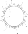
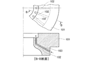
図8は従来の冷却構造を示す構成図であり、内燃機関のシリンダカバー101に複数のボア102を開け、これらのボア102内にそれぞれフィン付中子103を配置したことを示す。各フィンとボア102の内面との隙間は所定寸法t(図9参照)に設定される。このような冷却構造をシリンダライナに採用した例が特許文献1の図2に示されている。
FIG. 1 of Patent Document 1 will be described with reference to FIG. 8 below, and FIG. 3 of Patent Document 1 will be described with reference to FIG. In addition, the code | symbol was reassigned.
FIG. 8 is a block diagram showing a conventional cooling structure, and shows that a plurality of
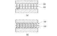
図9(a),(b)は従来の冷却構造の効果を示す説明図である。
(a)は冷却構造の拡大図であり、ボア102内にフィン付中子103を配置したことを示す。
(b)は冷却構造の作用図であり、ボア102内に冷却流体が流れたときに、ボア102内に冷却流体の乱れが生じたことを示す。
9A and 9B are explanatory views showing the effect of the conventional cooling structure.
(A) is an enlarged view of the cooling structure, and shows that the
FIG. 5B is an operation diagram of the cooling structure, and shows that the cooling fluid is disturbed in the
特許文献1では、図8において、細長いボア102を冷却流体の通路とするために、例えば、ウォータジャケットにてシリンダライナを冷却する方式に比べて冷却流体の流量を確保することが難しく、冷却性という点では不利となる。また、ボア102に近い部分しか冷却することが出来ないため、シリンダライナにボア102を開けた場合に、シリンダライナの全体を均一に冷却することは難しい。
例えば、冷却流体の流量を増やすためにボア102の本数を多くすれば、ボア102を開ける工数が増え、製造の手間が多く掛かる。
In Patent Document 1, in order to use the
For example, if the number of the
また、フィン付中子103は、軸部材と、この軸部材に固定した多数のフィンとからなるため、ボア102が長くなれば、軸部材の曲がりやフィンの外径のばらつきによって、各フィンとボア102の内面との隙間を所定寸法に保つことが難しく、この隙間が許容範囲を外れた場合に、この隙間を調整するにはフィン付中子103を交換する以外にないため、上記の隙間を精度よく形成できる構造が望まれる。
Further, the
更に、シリンダライナ一体型のシリンダブロックでは、例えば、シリンダライナが摩耗した場合に、シリンダライナを交換することができず、また、シリンダライナが摩耗しないようにシリンダブロックの全体を鋳鉄で製造した場合には、シリンダブロックの重量増を招く。 Further, in the cylinder block integrated with the cylinder liner, for example, when the cylinder liner is worn, the cylinder liner cannot be replaced, and when the entire cylinder block is made of cast iron so that the cylinder liner is not worn. This increases the weight of the cylinder block.
本発明の課題は、より均一に冷却でき、製造が容易で、フィンの先端とこのフィンに対向する壁との隙間を精度よく形成でき、しかも、シリンダライナ部分を交換可能であってシリンダブロックの重量を軽減できるシリンダライナの冷却構造を提供することにある。 The problem of the present invention is that cooling can be performed more uniformly, manufacturing is easy, the gap between the tip of the fin and the wall facing the fin can be formed with high accuracy, and the cylinder liner portion can be replaced. An object of the present invention is to provide a cylinder liner cooling structure capable of reducing the weight.
請求項1に係る発明は、ウォータポンプから供給された冷却水を、シリンダライナの外周に沿って形成されたウォータジャケット内に循環させてシリンダライナを冷却する冷却構造であって、ウォータジャケットを、シリンダライナとこのシリンダライナを囲む周壁とで構成し、これらのシリンダライナ及び周壁の一方にフィンを形成し、このフィンの先端と、シリンダライナ及び周壁の他方との間に狭窄空間を形成するとともに、ウォータジャケットの周囲に環状冷却プール部を形成し、この環状冷却プール部とウォータジャケットとを放射状に且つ周方向に等分した位置に配置した複数の放射状冷却通路で連通させ、この放射状冷却通路内を流れる冷却水を狭窄空間へ供給することを特徴とする。 The invention according to claim 1 is a cooling structure for cooling the cylinder liner by circulating the cooling water supplied from the water pump through a water jacket formed along the outer periphery of the cylinder liner. together constituted by a cylinder liner and a peripheral wall surrounding the cylinder liner, the fins is formed on one of these cylinder liner and the peripheral wall, to form the tip of the fin, a constricted space between the other of the cylinder liner and the peripheral wall An annular cooling pool portion is formed around the water jacket, and the annular cooling pool portion and the water jacket are communicated with each other by a plurality of radial cooling passages arranged radially and equally in the circumferential direction. The cooling water flowing inside is supplied to the constricted space .
ウォータジャケットを、シリンダライナとこのシリンダライナを囲む周壁とで構成することで、シリンダライナをウォータジャケット内の流量の多い冷却水で直接的に冷却することができ、冷却性を高めることができる。また、シリンダライナの周囲をウォータジャケットで囲むことで、シリンダライナの全体をより均一に冷却することができる。
更に、ウォータジャケットによる冷却構造であるから、細長いボアを多数開けた冷却構造に比べて、製造の手間を少なくすることができる。
By configuring the water jacket with the cylinder liner and the peripheral wall surrounding the cylinder liner, the cylinder liner can be directly cooled with cooling water having a large flow rate in the water jacket, and the cooling performance can be improved. In addition, by surrounding the cylinder liner with a water jacket, the entire cylinder liner can be cooled more uniformly.
Further, since the cooling structure is based on the water jacket, the labor for manufacturing can be reduced as compared with the cooling structure in which many elongated bores are opened.
また、複数の放射状冷却通路を放射状に且つ周方向に等分した位置に配置したことにより、環状冷却プール部からウォータジャケットへ円周方向に均等に冷却水を供給することができ、シリンダライナの上部を周方向により均一に冷却することができ、また、環状冷却プール部から、周壁とシリンダライナの外周面との間の隙間にも周方向に均等に冷却水を流すことができ、シリンダライナの中間部及び下部をも周方向により均一に冷却することができる。In addition, by arranging the plurality of radial cooling passages radially and equally spaced in the circumferential direction, the cooling water can be evenly supplied in the circumferential direction from the annular cooling pool portion to the water jacket. The upper part can be cooled more uniformly in the circumferential direction, and cooling water can be evenly flowed in the circumferential direction from the annular cooling pool portion to the gap between the peripheral wall and the outer peripheral surface of the cylinder liner. The intermediate part and the lower part can be cooled more uniformly in the circumferential direction.
請求項2に係る発明は、狭窄空間の隙間を、0.8〜1.0mmとしたことを特徴とする。
狭窄空間の隙間を、0.8〜1.0mmとしたことで、冷却水が狭窄空間を通過するときに、冷却水の流速を大きくすることができ、冷却水が狭窄空間を通過した直後に乱流を発生しやすくすることができ、シリンダライナから冷却水への熱伝達効率を向上させることができる。
The invention according to claim 2 is characterized in that the gap of the constricted space is set to 0.8 to 1.0 mm.
By setting the gap of the constriction space to 0.8 to 1.0 mm, the cooling water flow rate can be increased when the cooling water passes through the constriction space, and immediately after the cooling water passes through the constriction space. A turbulent flow can be easily generated, and the heat transfer efficiency from the cylinder liner to the cooling water can be improved.
例えば、狭窄空間の隙間が広い場合(即ち、狭窄空間の隙間が1.0mmを上回る場合)、狭窄空間の隙間を流れる冷却水の流量が多くなるとともに流速が小さくなり、冷却水はほぼ層流となって流れるため、乱流は発生しにくくなる。 For example, when the gap of the constriction space is wide (that is, when the gap of the constriction space exceeds 1.0 mm), the flow rate of the cooling water flowing through the gap of the constriction space increases and the flow velocity decreases, and the cooling water is almost laminar. Therefore, turbulent flow is less likely to occur.
また、例えば、狭窄空間の隙間が非常に狭い場合(即ち、狭窄空間の隙間が0.8mmを下回る場合)、狭窄空間の隙間を流れる冷却水の流量は非常に少なくなり、流速も小さくなって乱流は発生しにくくなる。 For example, when the gap of the constricted space is very narrow (that is, when the gap of the constricted space is less than 0.8 mm), the flow rate of the cooling water flowing through the gap of the constricted space becomes very small, and the flow velocity becomes small. the turbulence that a less likely to occur.
請求項1に係る発明では、ウォータジャケットを、シリンダライナとこのシリンダライナを囲む周壁とで構成したので、シリンダライナをウォータジャケット内の流量の多い冷却水で直接的に冷却することができ、冷却効率を高めることができる。また、シリンダライナの周囲をウォータジャケットで囲んだので、シリンダライナの全体をより均一に冷却することができ、シリンダライナの温度分布をより均一にすることができて、シリンダライナの熱変形を抑えることができる。
更に、ウォータジャケットによる冷却構造であるから、細長いボアを多数開けた冷却構造に比べて、製造の手間を少なくすることができ、コストを低減することができる。
In the invention according to claim 1, since the water jacket is constituted by the cylinder liner and the peripheral wall surrounding the cylinder liner, the cylinder liner can be directly cooled by the cooling water having a large flow rate in the water jacket. Efficiency can be increased. In addition, since the periphery of the cylinder liner is surrounded by a water jacket, the entire cylinder liner can be cooled more uniformly, the temperature distribution of the cylinder liner can be made more uniform, and thermal deformation of the cylinder liner can be suppressed. be able to.
Further, since the cooling structure is based on the water jacket, the manufacturing effort can be reduced and the cost can be reduced as compared with the cooling structure in which many elongated bores are opened.
また、複数の放射状冷却通路を放射状に且つ周方向に等分した位置に配置したことにより、環状冷却プール部からウォータジャケットへ円周方向に均等に冷却水を供給することができ、シリンダライナの上部を周方向により均一に冷却することができ、また、環状冷却プール部から、周壁とシリンダライナの外周面との間の隙間にも周方向に均等に冷却水を流すことができ、シリンダライナの中間部及び下部をも周方向により均一に冷却することができる。In addition, by arranging the plurality of radial cooling passages radially and equally spaced in the circumferential direction, the cooling water can be evenly supplied in the circumferential direction from the annular cooling pool portion to the water jacket. The upper part can be cooled more uniformly in the circumferential direction, and cooling water can be evenly flowed in the circumferential direction from the annular cooling pool portion to the gap between the peripheral wall and the outer peripheral surface of the cylinder liner. The intermediate part and the lower part can be cooled more uniformly in the circumferential direction.
請求項2に係る発明では、狭窄空間の隙間を、0.8〜1.0mmとしたので、冷却水が狭窄空間を通過するときに、冷却水の流速を大きくすることができ、冷却水が狭窄空間を通過した直後に乱流を発生しやすくすることができ、シリンダライナから冷却水への熱伝達効率を向上させることができて、シリンダライナを効果的に冷却することができる。 In the invention according to claim 2, since the gap of the constricted space is set to 0.8 to 1.0 mm, when the cooling water passes through the constricted space, the flow rate of the cooling water can be increased. can easily create turbulence immediately after passing through the constricted space, and can improve the efficiency of heat transfer from the cylinder liner into the cooling water, Ru can be effectively cooled cylinder liner.
本発明を実施するための最良の形態を添付図に基づいて以下に説明する。なお、図面は符号の向きに見るものとする。
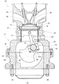
図1は本発明に係るシリンダライナの冷却構造を採用した内燃機関の断面図であり、内燃機関10は、シリンダブロック11と、このシリンダブロック11に備えるシリンダライナ12に移動自在に挿入したピストン13と、このピストン13にピストンピン14を介して連結したコンロッド16と、シリンダブロック11の下部に回転自在に取付けるとともにクランクピン17でコンロッド16をスイング自在に支持するクランクシャフト18とを備える。
The best mode for carrying out the present invention will be described below with reference to the accompanying drawings. The drawings are viewed in the direction of the reference numerals.
FIG. 1 is a cross-sectional view of an internal combustion engine employing a cylinder liner cooling structure according to the present invention. The
シリンダブロック11は、上部に設けたシリンダブロック本体21と、このシリンダブロック本体21の内側に嵌合させた別体のシリンダライナ12と、シリンダブロック本体21の下部に取付けたアッパークランクケース23とからなる。
The
シリンダブロック本体21は、シリンダライナ12を嵌合することで、このシリンダライナ12との間に、シリンダライナ12を冷却する冷却水を流すウォータジャケット26を形成し、このウォータジャケット26を含むシリンダライナ冷却部27を設けた部分である。
The
ここで、31はコンロッド16の大端部25とクランクピン17との間に介在させた軸受半体31a,31bからなる滑り軸受、32はクランクシャフト18に設けたカウンタウエイト、33はシリンダブロック11の上部にヘッドガスケット(不図示)を介して取付けたシリンダヘッド、34は吸気バルブ、36は排気バルブ、37は燃焼室、38はアッパークランクケース23とでクランクケースを形成するためにアッパークランクケース23の下部にボルト41・・・(・・・は複数個を示す。以下同じ。)で取付けたロワークランクケース、42はロワークランクケース38の下部にボルト44・・・で取付けたオイルパンである。
Here, 31 is a sliding bearing comprising
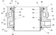
図2は本発明に係るシリンダライナの冷却構造を示す断面図であり、シリンダライナ12は、ほぼ筒状としたシリンダライナ本体部51と、このシリンダライナ本体部51の一端部に一体に設けた大径部52とからなり、シリンダライナ本体部51の外周面51aに複数の環状のフィン53を形成し、大径部52に環状の溝部54を形成したものである。なお、56はシリンダライナ本体部51の他端部に設けた小径部である。
FIG. 2 is a cross-sectional view showing the cooling structure of the cylinder liner according to the present invention. The
上記したシリンダライナ12の配置は、シリンダライナ12がウォータジャケット26に直接接する形式であり、ウェットライナ式と呼ばれ、例えば、シリンダライナがシリンダブロック本体と一体で鋳造された一体形のものに比べて、シリンダライナの破損や摩耗の際の交換が容易であり、又、シリンダライナがウォータジャケットに接しないドライライナ式に比べても、冷却性に優れる。
The arrangement of the
シリンダブロック本体21は、図示せぬウォータポンプに接続する複数の給水口61と、冷却水を一時的に貯えるために各給水口61に接続した環状の空間からなる第1貯水部62と、冷却水を溝部54の内壁54aに衝突させるために細く形成した複数の冷却水通孔63と、シリンダライナ12を挿入するために開けたライナ挿入穴64と、シリンダライナ12の大径部52を嵌合するためにライナ挿入穴64の一端部に形成した大径穴部66と、冷却水を一時的に貯えるためにライナ挿入穴64の他端部側に環状に形成した第2貯水部67と、この第2貯水部67から冷却水を図示せぬラジエータ側へ排水するための排水口68と、Oリング71,72を嵌めるために一端部側(即ち、大径穴部66である。)及び他端部側に設けたOリング溝73,74とを備える。なお、76は大径穴部66の側面であり、この側面76と前述の溝部54とで、冷却水を一時的に貯えるとともに冷却水通孔63から噴射した冷却水で乱流を形成するための第3貯水部77を形成する。
フィン53は、シリンダライナ12の軸方向に直交する面に沿って設けた環状の部分である。
The cylinder block
The
上記したOリング71,72で、シリンダブロック本体21とシリンダライナ12とのそれぞれの両端部をシールしたときに、ライナ挿入穴64、側面76、シリンダライナ12の溝部54、シリンダライナ本体部51の外周面51a及び第2貯水部67は、前述のウォータジャケット26を形成する部分であり、このウォータジャケット26、給水口61、第1貯水部62、冷却水通孔63は、前述のシリンダライナ冷却部27を構成する部分である。
また、給水口61、第1貯水部62、冷却水通孔63は、ウォータジャケット26へ冷却水を供給する冷却水供給部81を構成する部分である。
When both ends of the cylinder block
Further, the
図3は本発明に係る冷却水供給部を示す斜視図であり、環状の第1貯水部62と環状の第3貯水部77とを複数の冷却水通孔63で連結したことを示す。
このように、環状の第1貯水部62と環状の第3貯水部77とを細長い複数の冷却水通孔63で連結することにより、第1貯水部62から第3貯水部77へ供給する冷却水量を多くするとともに、各冷却水通孔63を通過した冷却水を第3貯水部77内へ勢いよく噴射させることができ、冷却水の乱流の生成を促進することができる。
FIG. 3 is a perspective view showing a cooling water supply unit according to the present invention, and shows that the annular first
Thus, the cooling supplied to the 3rd
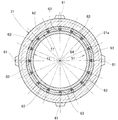
図4は図2の4−4線断面図であり、複数の冷却水通孔63を放射状に且つ周方向に等分した位置に配置したことを示す。これにより、第1貯水部62から第3貯水部77へ円周方向に均等に冷却水を供給することができ、シリンダライナ12の上部を周方向により均一に冷却することができ、また、第1貯水部62から、ライナ挿入穴64とシリンダライナ本体部51の外周面51aとの間の隙間にも周方向に均等に冷却水を流すことができ、シリンダライナの中間部及び下部をも周方向により均一に冷却することができる。
4 is a cross-sectional view taken along line 4-4 of FIG. 2, and shows that a plurality of cooling water passage holes 63 are arranged radially and equally divided in the circumferential direction. Thereby, the cooling water can be uniformly supplied in the circumferential direction from the first
また、4つの給水口61から第1貯水部62に流入した冷却水は、その流れが環状の第1貯水部62に溜まって安定するため、この第1貯水部62から各冷却水通孔63へもより均等に冷却水を流すことができる。
Further, the cooling water that has flowed into the first
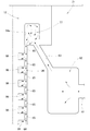
図5は図2のA部拡大図であり、シリンダライナ12の外周面51aに設けたフィン53の先端53aとシリンダブロック本体21のライナ挿入穴64との間に、径方向に狭めた環状の狭窄空間85を形成したことを示す。なお、86は隣り合うフィン53,53間の環状のフィン間空間である。
フィン53の先端53aとライナ挿入穴64とのクリアランスC、即ち狭窄空間85の厚さは0.8〜1.0mmである。
FIG. 5 is an enlarged view of part A in FIG. 2, and an annular shape narrowed in the radial direction between the
The clearance C between the
以上に述べたシリンダライナ冷却部の作用を図6及び図7で説明する。
図6は本発明に係るシリンダライナ冷却部の作用を示す第1作用図である。
冷却水が給水口61から第1貯水部62に流入すると、冷却水は、環状の第1貯水部62内の周方向の隅々にほぼ均等に行き渡り、各冷却水通孔63へほぼ均等に流れ込み、各冷却水通孔63から環状の第3貯水部77の周方向にほぼ均等に流れ込む。
The operation of the cylinder liner cooling section described above will be described with reference to FIGS.
FIG. 6 is a first operation diagram showing the operation of the cylinder liner cooling section according to the present invention.
When the cooling water flows into the first
冷却水通孔63は細長い孔であるから、冷却水は第3貯水部77へ勢いよく噴射し、第3貯水部77の内壁54aに大きな流速で衝突するため、矢印で示したように、第3貯水部77内の広い範囲に乱流が発生する。
Since the cooling
そして、冷却水は、第3貯水部77から、シリンダライナ12とライナ挿入穴64との間を通って矢印のようにフィン53に直交するように、あるいはフィン間空間86を周方向に流れる。
Then, the cooling water flows from the third
冷却水が狭窄空間85を通過するときには、狭窄空間85の厚さが小さいために冷却水の流速が大きくなるので、狭窄空間85(第3貯水部77の下流側に隣接する空間も狭窄空間85である。)を通過した直後には乱流が発生しやすくなり、冷却水が狭窄空間85から容積の大きなフィン間空間86に流入すると、冷却水の流速は急激に小さくなり、フィン間空間86の広い範囲で乱流が発生する。
When the cooling water passes through the constricted
この結果、フィン53による表面積の拡大に加えて、広い範囲の乱流発生によるシリンダライナ12から冷却水への熱伝達効率の向上により、シリンダライナ12の効果的な冷却が可能になる。
As a result, the
例えば、フィン53の先端53aとライナ挿入穴64との間の隙間が広く、狭窄空間85が無い場合(狭窄空間85の厚さが、1.0mmを越える場合)は、フィン53の先端53aとライナ挿入穴64との間の冷却水の流量が多くなるとともに冷却水の流速はそれほど大きくならず、冷却水はほぼ層流となって流れ、乱流は発生しにくい。
For example, when the gap between the
また、例えば、フィン53の先端53aとライナ挿入穴64との間の隙間が非常に狭く、狭窄空間85が存在する場合(狭窄空間85の厚さが、0.8mm未満の場合)は、フィン53の先端53aとライナ挿入穴64との間の冷却水の流量は非常に少なくなり、乱流はフィン間空間の一部でしか発生しなくなる。
Further, for example, when the gap between the
本発明では、狭窄空間85の厚さを0.8〜1.0mmに設定することで、フィン間空間86の広い範囲で速い乱流が発生するようにした。
また、シリンダライナ12は、シリンダブロック本体21とは別体であるため、シリンダライナ12をシリンダブロック本体21に組付ける前に、フィン53の高さ、即ちフィン53の外径を精度良く形成することができ、シリンダブロック本体21のライナ挿入穴64の内径を精度良く形成(シリンダブロック本体21に嵌合する大径部52及び小径部56をも精度良く形成しておく必要がある。)しておけば、狭窄空間85の厚さの精度を高めることができる。従って、各フィン間空間86での乱流発生を均一にすることができて、シリンダライナ12から冷却水への熱伝達効率をシリンダライナ12の軸方向でより均一にすることができる。
In the present invention, by setting the thickness of the constricted
Since the
また更に、第1貯水部62から斜め上方に各冷却水通孔63を延ばし、第3貯水部77から下方へウォータジャケット26を延ばしたことで、冷却水が第3貯水部77にて断面で鋭角的に急激に方向を変えるから、第3貯水部77における乱流生成を促進させることができる。
Furthermore, each cooling
図7は本発明に係るシリンダライナ冷却部の作用を示す第2作用図である。
各冷却水通孔63から第3貯水部77に噴出した冷却水は、第3貯水部77の内壁54aにほぼ垂直に又は垂直に衝突することで、乱流が第3貯水部77内の広い範囲で生成される。
FIG. 7 is a second operation diagram showing the operation of the cylinder liner cooling unit according to the present invention.
The cooling water ejected from each cooling
これにより、シリンダライナから第3貯水部77内の冷却水への熱伝達効率が向上し、シリンダライナの特に高温となる上部を周方向にほぼ均一に冷却して、効果的に温度を下げることができる。
As a result, the heat transfer efficiency from the cylinder liner to the cooling water in the
また、周方向にほぼ均一に冷却されて周方向に温度がほぼ均一となった冷却水は、そのままウォータジャケット26の下方に流れるため、シリンダライナの中間部及び下部においても、周方向に温度がほぼ均一になり、また、上部、即ち、高温部である燃焼室近辺を冷却し、温度の上昇した冷却水が中間部及び下部に流れるため、シリンダライナの軸方向温度も均一化されることで、シリンダライナの温度差による熱変形を抑えることができる。熱変形が小さい分、ピストンの加工が容易になり(熱変形が大だと楕円加工など手間が掛かる。)、更にピストン形状の簡略化が期待できる。
In addition, since the cooling water that has been substantially uniformly cooled in the circumferential direction and has a substantially uniform temperature in the circumferential direction flows directly below the
以上の図2及び図5で説明したように、本発明は第1に、ウォータポンプから供給された冷却水を、シリンダライナ12の外周に沿って形成されたウォータジャケット26内に循環させてシリンダライナ12を冷却する冷却構造であって、ウォータジャケット26を、シリンダライナ12とこのシリンダライナ12を囲む周壁としてのシリンダブロック本体21とで構成し、これらのシリンダライナ12及びシリンダブロック本体21の一方に複数のフィン53を形成し、これらのフィン53の先端53aと、シリンダライナ12及びシリンダブロック本体21の他方との間に狭窄空間85を形成し、この狭窄空間85によって冷却水に乱流を生成することを特徴とする。
As described above with reference to FIGS. 2 and 5, the present invention firstly circulates the cooling water supplied from the water pump in the
ウォータジャケット26を、シリンダライナ12とこのシリンダライナ12を囲むシリンダブロック本体21とで構成したので、シリンダライナ12をウォータジャケット26内の流量の多い冷却水で直接的に冷却することができ、冷却効率を高めることができる。
Since the
また、シリンダライナ12の周囲をウォータジャケット26で囲んだので、シリンダライナ12の全体をより均一に冷却することができ、シリンダライナ12の温度分布をより均一にすることができて、シリンダライナ12の熱変形を抑えることができる。
Further, since the periphery of the
更に、ウォータジャケット26による冷却構造であるから、細長いボアを多数開けた冷却構造に比べて、シリンダブロック11(図1参照)の製造の手間を少なくすることができ、コストを低減することができる。
Further, since the cooling structure is based on the
本発明は第2に、狭窄空間85の隙間を、0.8〜1.0mmとしたことを特徴とする。
狭窄空間85のクリアランス、即ち隙間Cを、0.8〜1.0mmとしたので、冷却水が狭窄空間85を通過するときに、冷却水の流速を大きくすることができ、冷却水が狭窄空間85を通過した直後に乱流を発生しやすくすることができ、シリンダライナ12から冷却水への熱伝達効率を向上させることができて、シリンダライナ12を効果的に冷却することができる。
Secondly, the present invention is characterized in that the gap of the constricted
Since the clearance of the constricted
本発明は第3に、ウォータポンプから供給された冷却水を、シリンダライナ12の外周に沿って形成されたウォータジャケット26内に循環させてシリンダライナ12を冷却する冷却構造であって、ウォータジャケット26の側壁を、シリンダブロック本体21と、このシリンダブロック本体21に嵌合させた別体のシリンダライナ12とで構成し、シリンダブロック本体21及びシリンダライナ12の一方に、ウォータジャケット26内に位置するフィン53を形成し、このフィン53の先端53aと、シリンダブロック本体21及びシリンダライナ12の他方との間に冷却水が通過する狭窄空間85を形成したことを特徴とする。
Thirdly, the present invention provides a cooling structure for cooling the
ウォータジャケット26の側壁をシリンダブロック本体21と別体のシリンダライナ12とで構成し、シリンダブロック本体21及びシリンダライナ12の一方に形成したフィン53の先端53aと、シリンダブロック本体21及びシリンダライナ12の他方との間に狭窄空間85を形成したので、シリンダブロック本体21及びシリンダライナ12の一方に容易に且つ精度良くフィン53を形成することができ、狭窄空間85の隙間Cを精度良く形成することができる。
The side wall of the
従って、例えば、狭窄空間85を複数設けた場合に、各狭窄空間85による冷却水の乱流生成をより均一にすることができ、シリンダライナ12から冷却水への熱伝達効率がシリンダライナ12各部でより均一になり、シリンダライナ12の温度分布の均一化を図ることができる。
Therefore, for example, when a plurality of constricted
また、別体のシリンダライナ12によって、シリンダライナ12が摩耗した場合には簡単に交換することができ、更に、シリンダブロック本体21を例えばアルミニウム合金で形成するとともにシリンダライナ12を鋳鉄で形成すれば、シリンダライナ一体型のシリンダブロック全体を鋳鉄で製造するのに比べて大幅な軽量化を図ることができる。
Further, when the
尚、本発明の実施形態では、図2に示したように、シリンダライナ12の外周面51aにフィン53を形成したが、これに限らず、シリンダブロック本体21のライナ挿入穴64に複数のフィンをシリンダライナ12の軸方向に直交する平面に沿って形成してもよい。
In the embodiment of the present invention, as shown in FIG. 2, the
本発明のシリンダライナの冷却構造は、ウエットライナ式内燃機関に好適である。 The cylinder liner cooling structure of the present invention is suitable for a wet liner type internal combustion engine.
10…内燃機関、12…シリンダライナ、21…周壁(シリンダブロック本体)、26…ウォータジャケット、53…フィン、53a…フィンの先端、54a…ウォータジャケットの壁(内壁)、62…環状冷却プール部(第1貯水部)、63…放射状冷却通路(冷却水通孔)、85…狭窄空間、C…狭窄空間の隙間。
DESCRIPTION OF
Claims (2)
前記ウォータジャケットを、前記シリンダライナとこのシリンダライナを囲む周壁とで構成し、これらのシリンダライナ及び周壁の一方にフィンを形成し、このフィンの先端と、前記シリンダライナ及び前記周壁の他方との間に狭窄空間を形成するとともに、前記ウォータジャケットの周囲に環状冷却プール部を形成し、この環状冷却プール部と前記ウォータジャケットとを放射状に且つ周方向に等分した位置に配置した複数の放射状冷却通路で連通させ、この放射状冷却通路内を流れる冷却水を前記狭窄空間へ供給することを特徴としたシリンダライナの冷却構造。 A cooling structure for cooling the cylinder liner by circulating cooling water supplied from a water pump in a water jacket formed along the outer periphery of the cylinder liner,
The water jacket is composed of the cylinder liner and a peripheral wall surrounding the cylinder liner, a fin is formed on one of the cylinder liner and the peripheral wall, and the tip of the fin and the other of the cylinder liner and the peripheral wall A plurality of radial spaces are formed by forming a constricted space between them and forming an annular cooling pool portion around the water jacket and radially and circumferentially dividing the annular cooling pool portion and the water jacket. A cooling structure for a cylinder liner, characterized in that the cooling water is communicated by a cooling passage and the cooling water flowing through the radial cooling passage is supplied to the constricted space .
Priority Applications (3)
| Application Number | Priority Date | Filing Date | Title |
|---|---|---|---|
| JP2004153660A JP4276128B2 (en) | 2004-05-24 | 2004-05-24 | Cylinder liner cooling structure |
| EP05010253.2A EP1600621B1 (en) | 2004-05-24 | 2005-05-11 | Cylinder liner cooling structure |
| US11/128,242 US7104226B2 (en) | 2004-05-24 | 2005-05-13 | Cylinder liner cooling structure |
Applications Claiming Priority (1)
| Application Number | Priority Date | Filing Date | Title |
|---|---|---|---|
| JP2004153660A JP4276128B2 (en) | 2004-05-24 | 2004-05-24 | Cylinder liner cooling structure |
Publications (2)
| Publication Number | Publication Date |
|---|---|
| JP2005337037A JP2005337037A (en) | 2005-12-08 |
| JP4276128B2 true JP4276128B2 (en) | 2009-06-10 |
Family
ID=35490891
Family Applications (1)
| Application Number | Title | Priority Date | Filing Date |
|---|---|---|---|
| JP2004153660A Expired - Lifetime JP4276128B2 (en) | 2004-05-24 | 2004-05-24 | Cylinder liner cooling structure |
Country Status (1)
| Country | Link |
|---|---|
| JP (1) | JP4276128B2 (en) |
Cited By (1)
| Publication number | Priority date | Publication date | Assignee | Title |
|---|---|---|---|---|
| US20250264073A1 (en) * | 2024-02-15 | 2025-08-21 | Progress Rail Locomotive Inc. | Cylinder liner having coolant flow balancer and engine power assembly using same |
Families Citing this family (4)
| Publication number | Priority date | Publication date | Assignee | Title |
|---|---|---|---|---|
| JP2012021406A (en) * | 2010-07-12 | 2012-02-02 | Mitsubishi Heavy Ind Ltd | Cylinder liner |
| US8485147B2 (en) * | 2011-07-29 | 2013-07-16 | Achates Power, Inc. | Impingement cooling of cylinders in opposed-piston engines |
| CN107883804A (en) * | 2017-12-25 | 2018-04-06 | 宣城铁凝机械有限公司 | A kind of cylinder water cooling component |
| CN114320643A (en) * | 2021-12-31 | 2022-04-12 | 江苏紫金动力股份有限公司 | Diesel engine matrix cylinder sleeve and production process thereof |
-
2004
- 2004-05-24 JP JP2004153660A patent/JP4276128B2/en not_active Expired - Lifetime
Cited By (2)
| Publication number | Priority date | Publication date | Assignee | Title |
|---|---|---|---|---|
| US20250264073A1 (en) * | 2024-02-15 | 2025-08-21 | Progress Rail Locomotive Inc. | Cylinder liner having coolant flow balancer and engine power assembly using same |
| US12473871B2 (en) * | 2024-02-15 | 2025-11-18 | Progress Rail Locomotive Inc. | Cylinder liner having coolant flow balancer and engine power assembly using same |
Also Published As
| Publication number | Publication date |
|---|---|
| JP2005337037A (en) | 2005-12-08 |
Similar Documents
| Publication | Publication Date | Title |
|---|---|---|
| EP1600621B1 (en) | Cylinder liner cooling structure | |
| JP4395002B2 (en) | Cylinder block cooling structure | |
| JP5062071B2 (en) | Internal combustion engine cylinder block | |
| JP4279713B2 (en) | Cylinder block cooling structure | |
| JP2008231937A (en) | Cylinder block | |
| JP5175808B2 (en) | Internal combustion engine cooling structure | |
| JP4276128B2 (en) | Cylinder liner cooling structure | |
| JP5968431B2 (en) | Heat transfer device | |
| JP4375731B2 (en) | Cylinder liner cooling structure | |
| JP4279760B2 (en) | Cooling device for internal combustion engine | |
| JP6455136B2 (en) | Cylinder block | |
| TWI650921B (en) | Liquid cooled motor shell heat dissipation structure | |
| US20160102596A1 (en) | Piston crown cooling feature for diesel engines | |
| JP6465364B2 (en) | Engine cooling structure | |
| JP2010229831A (en) | Internal combustion engine | |
| KR101163824B1 (en) | Cooling device and insert for water jacket of internal combustion engine | |
| JP5569370B2 (en) | engine | |
| JP2012112332A (en) | Cylinder block of internal combustion engine | |
| JP7673592B2 (en) | Engine oil passage structure | |
| JP2001159369A (en) | Engine cooling structure | |
| JP6642244B2 (en) | Cylinder block | |
| JP4850672B2 (en) | Cylinder block | |
| SU1134746A2 (en) | Device for air and liqiud cooling of engine | |
| JP6413755B2 (en) | Water jacket spacer | |
| JP2005325712A (en) | Internal combustion engine |
Legal Events
| Date | Code | Title | Description |
|---|---|---|---|
| A621 | Written request for application examination |
Free format text: JAPANESE INTERMEDIATE CODE: A621 Effective date: 20061201 |
|
| A131 | Notification of reasons for refusal |
Free format text: JAPANESE INTERMEDIATE CODE: A131 Effective date: 20080819 |
|
| A521 | Written amendment |
Free format text: JAPANESE INTERMEDIATE CODE: A523 Effective date: 20081016 |
|
| TRDD | Decision of grant or rejection written | ||
| A01 | Written decision to grant a patent or to grant a registration (utility model) |
Free format text: JAPANESE INTERMEDIATE CODE: A01 Effective date: 20090303 |
|
| A01 | Written decision to grant a patent or to grant a registration (utility model) |
Free format text: JAPANESE INTERMEDIATE CODE: A01 |
|
| A61 | First payment of annual fees (during grant procedure) |
Free format text: JAPANESE INTERMEDIATE CODE: A61 Effective date: 20090305 |
|
| R150 | Certificate of patent or registration of utility model |
Free format text: JAPANESE INTERMEDIATE CODE: R150 |
|
| FPAY | Renewal fee payment (event date is renewal date of database) |
Free format text: PAYMENT UNTIL: 20120313 Year of fee payment: 3 |
|
| FPAY | Renewal fee payment (event date is renewal date of database) |
Free format text: PAYMENT UNTIL: 20130313 Year of fee payment: 4 |