JP4274732B2 - Trimming machine - Google Patents
Trimming machine Download PDFInfo
- Publication number
- JP4274732B2 JP4274732B2 JP2002037787A JP2002037787A JP4274732B2 JP 4274732 B2 JP4274732 B2 JP 4274732B2 JP 2002037787 A JP2002037787 A JP 2002037787A JP 2002037787 A JP2002037787 A JP 2002037787A JP 4274732 B2 JP4274732 B2 JP 4274732B2
- Authority
- JP
- Japan
- Prior art keywords
- housing
- auxiliary handle
- handle
- attached
- trimming machine
- Prior art date
- Legal status (The legal status is an assumption and is not a legal conclusion. Google has not performed a legal analysis and makes no representation as to the accuracy of the status listed.)
- Expired - Fee Related
Links
Images


Description
【0001】
【発明の属する技術分野】
本発明は、生垣や植木等の刈り込みをする刈込機に関するものである。
【0002】
【従来の技術】
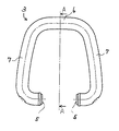
刈込機の補助ハンドル3は図5、図7に示すように、円柱状部材を略C字状に形成し、握り部6、腕部7、取付部5が一直線状に配置された形状となっている。
【0003】
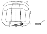
補助ハンドル3をハウジング1に装着する際は、図6に示すハウジング1に角度αをもって形成された補助ハンドル取付穴8に、補助ハンドル3の取付部5に形成された凸部を嵌合し、図7に示すボルト9で補助ハンドル3をハウジング1に固定する。
【0004】
刈込作業の際には、図9に示すようにハウジング1に一体成形された主ハンドル2と補助ハンドル3をそれぞれ掴み、ハウジング1前部に装着された刈込刃4により、生垣や植木等を切断する。
【0005】
【発明が解決しようとする課題】
作業姿勢や個人の体格が変わってもハウジング前部に装着された補助ハンドルの握り部の位置は固定されているため、操作性が悪く感じられる場合がある。
【0006】
本発明の目的は、補助ハンドルの取り付け及び取り外しが容易に行え、仕事の姿勢に合わせて、より持ち易い位置を選択できる、作業性の良い刈込機を提供することである。
【0007】
【課題を解決するための手段】
上記の目的を達成するために本発明は、ハウジングに形成された主ハンドルと、前記ハウジングに着脱可能に取り付けられ、握り部、腕部、取付部からなるほぼC字状の補助ハンドルとを有する刈込機において、前記腕部は、角度βで曲げられて形成されると共に、前記腕部の取付部側直線部分が、前記ハウジングに対して所定角度α傾斜した状態で取り付けられ、前記補助ハンドルを前記ハウジングに左右反転して取り付けたときにも、前記腕部の取付部側直線部分が、前期ハウジングに対し所定角度α傾斜した状態で取り付けられ、前記握り部の前記主ハンドルに対する高さと、前記握り部の前記主ハンドルに対する前後方向の位置が変化するようにしたことに一つの特徴を有する。
【0008】
【発明の実施の形態】
本発明による補助ハンドル3の一実施形態を図1から図4に示す。
補助ハンドル3は略C字状で、腕部7は角度βで曲げられており、取付部5、腕部7及び握り部6は一直線状に形成されていない。また、補助ハンドル3のハウジング1への装着方法は従来の技術と同様である。
【0009】
このような構成とすることにより、図3、図4に示すように、補助ハンドル3のハウジング1への取り付け向きを変えるだけで、補助ハンドル3の握り部6の位置を変えることができ、刈込時の刈込機の保持姿勢によって操作しやすい補助ハンドル3の握り部6の位置を選択することが可能となる。すなわち、図4の握り部6は、図3の握り部6より高い位置に位置し、かつ主ハンドル2の長手方向に沿った位置が主ハンドル2により近い位置となっている。
【0010】
【発明の効果】
本発明によれば、部品を追加することなしに仕事の姿勢に合わせて、より持ち易い位置を選択でき、作業性のよい刈込機を提供できる。
【図面の簡単な説明】
【図1】本発明を構成する補助ハンドルの一実施形態を示す正面図。
【図2】図1のA−A断面図。
【図3】補助ハンドルを刈込機に装着した一例を示す側面図。
【図4】図3の補助ハンドルの取付方向を変えた側面図。
【図5】従来の補助ハンドルを示す図2相当図。
【図6】補助ハンドル取付穴を示す刈込機の側面図。
【図7】補助ハンドルの固定方法を示す刈込機の正面図。
【図8】従来の補助ハンドルを取り付けた刈込機の側面図。
【図9】刈込機の使用状態を示す斜視図。
【符号の説明】
1はハウジング、2は主ハンドル、3は補助ハンドル、4は刈込刃、5は取付部、6は握り部、7は腕部、8は補助ハンドル取付穴、9はボルトである。[0001]
BACKGROUND OF THE INVENTION
The present invention relates to a trimming machine that trims hedges, planted trees, and the like.
[0002]
[Prior art]
As shown in FIGS. 5 and 7, the
[0003]
When the
[0004]
In the cutting operation, as shown in FIG. 9, the
[0005]
[Problems to be solved by the invention]
Even if the working posture and the personal physique change, the position of the grip portion of the auxiliary handle attached to the front portion of the housing is fixed, so that the operability may be felt badly.
[0006]
An object of the present invention is to provide a mower with good workability, in which an auxiliary handle can be easily attached and detached, and a position that is easier to hold can be selected according to the posture of work.
[0007]
[Means for Solving the Problems]
To achieve the above object, the present invention has a main handle formed in a housing and a substantially C-shaped auxiliary handle that is detachably attached to the housing and includes a grip portion, an arm portion, and an attachment portion. In the trimming machine, the arm portion is formed by being bent at an angle β, and the attachment portion side straight portion of the arm portion is attached in a state inclined at a predetermined angle α with respect to the housing, and the auxiliary handle is Even when the left and right are attached to the housing, the attachment portion side straight portion of the arm portion is attached in a state inclined at a predetermined angle α with respect to the previous housing, and the height of the grip portion relative to the main handle, One feature is that the position of the grip portion in the front-rear direction with respect to the main handle changes .
[0008]
DETAILED DESCRIPTION OF THE INVENTION
One embodiment of the
The
[0009]
With this configuration, as shown in FIGS. 3 and 4, the position of the grip portion 6 of the
[0010]
【The invention's effect】
According to the present invention, it is possible to select a position that is easier to hold in accordance with the work posture without adding parts, and it is possible to provide a trimming machine with good workability.
[Brief description of the drawings]
FIG. 1 is a front view showing an embodiment of an auxiliary handle constituting the present invention.
FIG. 2 is a cross-sectional view taken along line AA in FIG.
FIG. 3 is a side view showing an example in which an auxiliary handle is mounted on a trimming machine.
4 is a side view in which the mounting direction of the auxiliary handle in FIG. 3 is changed.
FIG. 5 is a view corresponding to FIG. 2 showing a conventional auxiliary handle.
FIG. 6 is a side view of a trimming machine showing an auxiliary handle mounting hole.
FIG. 7 is a front view of a trimming machine showing a method of fixing an auxiliary handle.
FIG. 8 is a side view of a conventional trimming machine equipped with an auxiliary handle.
FIG. 9 is a perspective view showing a usage state of the trimming machine.
[Explanation of symbols]
Reference numeral 1 denotes a housing, 2 denotes a main handle, 3 denotes an auxiliary handle, 4 denotes a cutting blade, 5 denotes an attachment portion, 6 denotes a grip portion, 7 denotes an arm portion, 8 denotes an auxiliary handle attachment hole, and 9 denotes a bolt.
Claims (2)
前記腕部は、角度βで曲げられて形成されると共に、前記腕部の取付部側直線部分が、前記ハウジングに対して所定角度α傾斜した状態で取り付けられ、
前記補助ハンドルを前記ハウジングに左右反転して取り付けたときにも、前記腕部の取付部側直線部分が、前期ハウジングに対し所定角度α傾斜した状態で取り付けられ、
前記握り部の前記主ハンドルに対する高さと、前記握り部の前記主ハンドルに対する前後方向の位置が変化するようにしたことを特徴とする刈込機。 In a trimming machine having a main handle formed in a housing and a substantially C-shaped auxiliary handle that is detachably attached to the housing and includes a grip portion, an arm portion, and an attachment portion.
The arm portion is formed by being bent at an angle β, and the attachment portion side straight portion of the arm portion is attached in a state inclined at a predetermined angle α with respect to the housing,
Even when the auxiliary handle is attached to the housing while being reversed left and right, the attachment portion side straight portion of the arm portion is attached in a state inclined at a predetermined angle α with respect to the previous housing,
A trimming machine characterized in that the height of the grip portion relative to the main handle and the position of the grip portion relative to the main handle change in the front-rear direction.
Priority Applications (1)
| Application Number | Priority Date | Filing Date | Title |
|---|---|---|---|
| JP2002037787A JP4274732B2 (en) | 2002-02-15 | 2002-02-15 | Trimming machine |
Applications Claiming Priority (1)
| Application Number | Priority Date | Filing Date | Title |
|---|---|---|---|
| JP2002037787A JP4274732B2 (en) | 2002-02-15 | 2002-02-15 | Trimming machine |
Publications (3)
| Publication Number | Publication Date |
|---|---|
| JP2003235352A JP2003235352A (en) | 2003-08-26 |
| JP2003235352A5 JP2003235352A5 (en) | 2005-06-16 |
| JP4274732B2 true JP4274732B2 (en) | 2009-06-10 |
Family
ID=27779275
Family Applications (1)
| Application Number | Title | Priority Date | Filing Date |
|---|---|---|---|
| JP2002037787A Expired - Fee Related JP4274732B2 (en) | 2002-02-15 | 2002-02-15 | Trimming machine |
Country Status (1)
| Country | Link |
|---|---|
| JP (1) | JP4274732B2 (en) |
Families Citing this family (2)
| Publication number | Priority date | Publication date | Assignee | Title |
|---|---|---|---|---|
| JP5707057B2 (en) * | 2010-05-20 | 2015-04-22 | 株式会社マキタ | Handheld power work machine |
| JP5924589B2 (en) * | 2012-11-30 | 2016-05-25 | 株式会社マキタ | Working machine |
-
2002
- 2002-02-15 JP JP2002037787A patent/JP4274732B2/en not_active Expired - Fee Related
Also Published As
| Publication number | Publication date |
|---|---|
| JP2003235352A (en) | 2003-08-26 |
Similar Documents
| Publication | Publication Date | Title |
|---|---|---|
| US20120102766A1 (en) | Chainsaw arrangement | |
| JP4421526B2 (en) | Electric tool with detachable extension handle | |
| US6711971B1 (en) | Roofing removal apparatus | |
| JP4274732B2 (en) | Trimming machine | |
| USD539621S1 (en) | Handle | |
| CA2476086A1 (en) | Pivoting handle assembly for power tool | |
| JP5287515B2 (en) | Electric tool | |
| CA2350471A1 (en) | Snow removing machine with snow removing plate | |
| JP6173266B2 (en) | Walking type work machine | |
| JP2004261053A (en) | Hand-carry type pruning machine | |
| JP3945421B2 (en) | Trimming machine | |
| JP4325383B2 (en) | Electric tool | |
| JP2008263885A (en) | Bagging operation part of combine harvester | |
| JPH0591285U (en) | Protector for mower | |
| JP2522540Y2 (en) | Mowing machine | |
| US6769341B2 (en) | Sheet cutting device | |
| EP2422945B1 (en) | Chainsaw arrangement | |
| JP3682181B2 (en) | Combine | |
| USD1003950S1 (en) | Motor housing for grass cutter | |
| JP5707057B2 (en) | Handheld power work machine | |
| JP2012065622A (en) | Power tool and attachment | |
| JP2004229521A (en) | Combine harvester | |
| JP5575541B2 (en) | Hand-held work machine | |
| JP2002034315A (en) | Handle device of mower | |
| JP2516659Y2 (en) | Cutting device for root cutting of garden trees |
Legal Events
| Date | Code | Title | Description |
|---|---|---|---|
| A521 | Written amendment |
Free format text: JAPANESE INTERMEDIATE CODE: A523 Effective date: 20040909 |
|
| A621 | Written request for application examination |
Free format text: JAPANESE INTERMEDIATE CODE: A621 Effective date: 20040909 |
|
| A131 | Notification of reasons for refusal |
Free format text: JAPANESE INTERMEDIATE CODE: A131 Effective date: 20060523 |
|
| A521 | Written amendment |
Free format text: JAPANESE INTERMEDIATE CODE: A523 Effective date: 20060724 |
|
| A02 | Decision of refusal |
Free format text: JAPANESE INTERMEDIATE CODE: A02 Effective date: 20070313 |
|
| RD02 | Notification of acceptance of power of attorney |
Free format text: JAPANESE INTERMEDIATE CODE: A7422 Effective date: 20081226 |
|
| A521 | Written amendment |
Free format text: JAPANESE INTERMEDIATE CODE: A523 Effective date: 20090121 |
|
| A01 | Written decision to grant a patent or to grant a registration (utility model) |
Free format text: JAPANESE INTERMEDIATE CODE: A01 |
|
| A61 | First payment of annual fees (during grant procedure) |
Free format text: JAPANESE INTERMEDIATE CODE: A61 Effective date: 20090303 |
|
| R150 | Certificate of patent or registration of utility model |
Free format text: JAPANESE INTERMEDIATE CODE: R150 |
|
| FPAY | Renewal fee payment (event date is renewal date of database) |
Free format text: PAYMENT UNTIL: 20120313 Year of fee payment: 3 |
|
| FPAY | Renewal fee payment (event date is renewal date of database) |
Free format text: PAYMENT UNTIL: 20120313 Year of fee payment: 3 |
|
| FPAY | Renewal fee payment (event date is renewal date of database) |
Free format text: PAYMENT UNTIL: 20130313 Year of fee payment: 4 |
|
| FPAY | Renewal fee payment (event date is renewal date of database) |
Free format text: PAYMENT UNTIL: 20140313 Year of fee payment: 5 |
|
| FPAY | Renewal fee payment (event date is renewal date of database) |
Free format text: PAYMENT UNTIL: 20140313 Year of fee payment: 5 |
|
| FPAY | Renewal fee payment (event date is renewal date of database) |
Free format text: PAYMENT UNTIL: 20150313 Year of fee payment: 6 |
|
| LAPS | Cancellation because of no payment of annual fees |