JP4274172B2 - Electronic device, control method thereof, and control program thereof - Google Patents

Electronic device, control method thereof, and control program thereof Download PDF

Info

Publication number
JP4274172B2
JP4274172B2 JP2005355906A JP2005355906A JP4274172B2 JP 4274172 B2 JP4274172 B2 JP 4274172B2 JP 2005355906 A JP2005355906 A JP 2005355906A JP 2005355906 A JP2005355906 A JP 2005355906A JP 4274172 B2 JP4274172 B2 JP 4274172B2
Authority
JP
Japan
Prior art keywords
cradle
digital camera
main body
mode
electronic device
Prior art date
Legal status (The legal status is an assumption and is not a legal conclusion. Google has not performed a legal analysis and makes no representation as to the accuracy of the status listed.)
Expired - Fee Related
Application number
JP2005355906A
Other languages
Japanese (ja)
Other versions
JP2006136012A (en
JP2006136012A5 (en
Inventor
智 片貝
Current Assignee (The listed assignees may be inaccurate. Google has not performed a legal analysis and makes no representation or warranty as to the accuracy of the list.)
Casio Computer Co Ltd
Original Assignee
Casio Computer Co Ltd
Priority date (The priority date is an assumption and is not a legal conclusion. Google has not performed a legal analysis and makes no representation as to the accuracy of the date listed.)
Filing date
Publication date
Application filed by Casio Computer Co Ltd filed Critical Casio Computer Co Ltd
Priority to JP2005355906A priority Critical patent/JP4274172B2/en
Publication of JP2006136012A publication Critical patent/JP2006136012A/en
Publication of JP2006136012A5 publication Critical patent/JP2006136012A5/ja
Application granted granted Critical
Publication of JP4274172B2 publication Critical patent/JP4274172B2/en
Anticipated expiration legal-status Critical
Expired - Fee Related legal-status Critical Current

Links

Images

Description

本発明は、電子機器、その制御方法、及びその制御プログラムに関する。
The present invention, electronic equipment, a control method, and a control program.

従来、携帯情報端末(PDA:Personal Digital Assistant)や電子手帳、デジタルカメラ等の携帯型の電子機器においては、内蔵電池の充電や、外部のパーソナルコンピュータ(PC)等の外部機器との間でデータ通信を行うための装置としてクレードル(cradle)と呼ばれる接続台が使用されている。一般に、クレードルは、電子機器を固定して保持する本体の所定箇所に、電子機器側に設けられているものと対をなす接続コネクタが設けられた構成を有しており、それに電子機器を装着(載置)することにより電子機器への充電が可能となっている。また、電子機器と外部装置(PC等)との間のデータ通信に使用されるクレードルにあっては、前記接続コネクタとは別に、USB(Universal Serial Bus)やRS−232C等によりPC等とケーブル接続するための接続コネクタが本体に設けられている。   Conventionally, in portable electronic devices such as personal digital assistants (PDAs), electronic notebooks, and digital cameras, charging internal batteries and data with external devices such as an external personal computer (PC) A connection table called a cradle is used as a device for performing communication. In general, a cradle has a configuration in which a connection connector that is paired with a connector provided on the electronic device side is provided at a predetermined position of a main body that holds and holds the electronic device. (Mounting) makes it possible to charge the electronic device. In addition, in a cradle used for data communication between an electronic device and an external device (such as a PC), a cable connected to a PC or the like via a USB (Universal Serial Bus), RS-232C, or the like separately from the connection connector. A connection connector for connection is provided on the main body.

そして、前述したようなクレードルと電子機器とからなる接続システムとしては、例えばPC等との間でデータ通信を行うための動作モードとして複数種の通信モードが用意されたデジタルカメラにおいて、それがクレードルに装着(載置)された状態で電源スイッチがオンされると、予めセットアップされている所定の通信モードが自動的に立ち上がり、その通信モードでの動作を開始するものが知られている(例えば、特許文献1参照。)。
特開2002−218300号公報(第8頁、図9)
As a connection system including the cradle and the electronic device as described above, for example, in a digital camera in which a plurality of communication modes are prepared as operation modes for performing data communication with a PC or the like, this is a cradle. It is known that when a power switch is turned on while mounted (mounted), a predetermined communication mode that has been set up in advance automatically starts and starts operation in that communication mode (for example, , See Patent Document 1).
Japanese Patent Laid-Open No. 2002-218300 (page 8, FIG. 9)

しかしながら、前述したようなデジタルカメラとクレードルとからなる接続システムにおいては、ユーザーがデジタルカメラの通信機能を使用する場合には、それをクレードルに装着する以前に、使用する通信モードをカメラ側において設定しておく必要がある。しかも、一般に、デジタルカメラにおいては、ユーザーにより設定可能なパラメータや動作等の設定項目の種類が多岐に渡っており、前述した所望の通信モードの設定に際しては、まず設定項目として通信モードを選択した後、さらに複数用意されている通信モードから所望するモードを選択するという作業が要求されている。   However, in the connection system consisting of a digital camera and a cradle as described above, when the user uses the communication function of the digital camera, the communication mode to be used is set on the camera side before mounting it on the cradle. It is necessary to keep it. Moreover, in general, in digital cameras, there are a wide variety of setting items such as parameters and operations that can be set by the user. When setting the desired communication mode, the communication mode was first selected as the setting item. Thereafter, an operation of selecting a desired mode from a plurality of prepared communication modes is required.

このため、前述したように、クレードルに装着した状態で電源スイッチをオンするだけで通信モードを自動的を立ち上げることができたとしても、所望の通信機能を使用する場合には、その準備操作が依然として煩雑であるという問題があった。   For this reason, as described above, even if the communication mode can be automatically started only by turning on the power switch with the cradle mounted, if the desired communication function is used, the preparatory operation is performed. However, there was a problem that it was still complicated.

本発明は、かかる従来の課題に鑑みてなされたものであり、電子機器を接続台に装着して所定の機能を利用する際の作業性を向上させる電子機器、その制御方法、及びその制御プログラムを提供することを目的とする。
The present invention, according in view of the conventional problems has been made, workability electronic equipment Ru improve when using a predetermined function by mounting the electronic apparatus in connection table, its control method and, The purpose is to provide the control program.

請求項1に記載の発明は、本体部と、当該本体部に対して回転可能に設けられた撮像部を備える電子機器において、当該電子機器を接続台に接続した時に、前記撮像部と前記本体部との位置関係を確認する確認手段と、この確認手段により確認された位置関係に対応する、この電子機器の動作モードを設定する設定手段と、を備えたことを特徴とする電子機器を提供する。
The invention of claim 1 includes a main body portion, the electronic apparatus including an imaging unit which is provided rotatably with respect to the main body portion, when connecting the electronic device to the connection base, a front SL imaging section to a confirmation means for confirming the positional relationship between the previous SL Main body portion, corresponding to the position relationship confirmed by the confirmation means, and setting means for setting an operation mode of the electronic apparatus, comprising the to provide that electronic equipment.

請求項2に記載の発明は、前記確認手段は、少なくとも3つの位置関係を確認するものであることを特徴とする請求項1に記載の電子機器を提供する。
The invention according to claim 2, wherein the check means provides a child apparatus electrodeposition according to claim 1, characterized in that to check at least three positional relationships.

請求項3に記載の発明は、前記電子機器は、電源オフ状態である場合、前記接続台に接続されることにより電源オン状態となることを特徴とする請求項1または2に記載の電子機器を提供する。
The invention according to claim 3, wherein the electronic apparatus, when a power-off state, the child collector according to claim 1 or 2, characterized in that the power-on state by being connected to the connecting base Provide equipment.

請求項4に記載の発明は、前記動作モードの一つとしてデータ転送モードを備えると共に、当該データ転送モードが設定された時に前記電子機器内のデータを前記接続台へ転送するデータ転送手段を具備し、前記設定手段は、前記確認手段により確認された位置関係が所定のものであった時に前記データ転送モードを設定し、前記データ転送手段に前記データの転送を行わせることを特徴とする、請求項1ないし3の何れか1項に記載の電子機器を提供する。
Invention according to claim 4, when a data transfer mode as one of the operation modes together, the data transfer means for transferring data in which the said at data transfer mode is set electronic apparatus to the connecting base And the setting means sets the data transfer mode when the positional relationship confirmed by the confirmation means is a predetermined one, and causes the data transfer means to transfer the data. provides a child apparatus electrodeposition according to any one of claims 1 to 3.

請求項5に記載の発明は、前記動作モードの一つとしてPCカメラモードを備えると共に、当該PCカメラモードが設定された時に前記撮像部により画像を撮影すると共にその撮影画像を前記接続台へ転送するPCカメラ手段を具備し、前記設定手段は、前記確認手段により確認された位置関係が所定のものであった時に、前記PCカメラモードを設定し、前記PCカメラ手段に画像の撮影及びその撮影画像の転送を行わせることを特徴とする請求項1ないし3の何れか1項に記載の電子機器を提供する。
The invention according to claim 5, Rutotomoni includes a PC camera mode as one of the operation mode, the photographed image while photographing the image by the imaging unit when the PC camera mode is set to the connecting base PC camera means for transferring, and when the positional relationship confirmed by the confirmation means is a predetermined one, the setting means sets the PC camera mode, captures an image to the PC camera means, and characterized in that to perform the transfer of the captured images, to provide a child apparatus electrodeposition according to any one of claims 1 to 3.

請求項に記載の発明は、本体部と、当該本体部に対して回転可能に設けられた撮像部を備える電子機器の制御方法であって、前記電子機器を接続台に接続した時に、前記撮像部と前記本体部との位置関係を確認する確認工程と、この確認工程により確認された位置関係に対応する前記電子機器の動作モードを設定する設定工程と、を備えたことを特徴とする電子機器の制御方法を提供する。
The invention according to claim 6 is a method for controlling an electronic device including a main body portion and an imaging unit rotatably provided with respect to the main body portion, and when the electronic device is connected to a connection base, a confirmation step of confirming the positional relationship of the serial imaging section and the previous SL Main body portion, further comprising a, a setting step of setting an operation mode of the electronic device corresponding to the position relationship confirmed by the checking step a control method of that electronic equipment be characterized.

請求項に記載の発明は、本体部と、当該本体部に対して回転可能に設けられた撮像部を備える電子機器の制御プログラムであって、前記電子機器を接続台に接続した時に、前記撮像部と前記本体部との位置関係を確認する確認ステップと、この確認ステップにより確認された位置関係に対応する前記電子機器の動作モードを設定する設定ステップと、を備えることを特徴とする電子機器の制御プログラムを提供する。
The invention according to claim 7 is a control program for an electronic device including a main body portion and an imaging unit rotatably provided with respect to the main body portion, and when the electronic device is connected to a connection base, a confirmation step of confirming the positional relationship between the serial imaging section and the front Symbol Main body portion, and a setting step of setting an operation mode of the electronic device corresponding to the positional relationship which has been confirmed by the confirmation step, in that it comprises providing a control program for that electronic equipment be characterized.

請求項に記載の発明は、前記確認ステップは、少なくとも3つの位置関係を確認することを特徴とする、請求項に記載の電子機器の制御プログラムを提供する。
The invention according to claim 8, wherein the confirmation step is characterized to confirm at least three positional relationships, to provide a control program of the electronic device according to claim 7.

請求項に記載の発明は、前記電子機器が電源オフ状態である場合、前記接続台に接続されることにより電源オン状態とするステップを備えることを特徴とする、請求項またはに記載の電子機器の制御プログラムを提供する。 The invention according to claim 9, when the electronic device is in a power-off state, characterized in that it comprises the steps of a power-on state by being connected to the connecting base, according to claim 7 or 8 providing electronic devices of the control program.

以上説明したように本発明においては、電子機器を接続台へ装着する際、その所定部位の向きを選択的に変えることにより、電子機器に異なる動作モードを設定することができるようにした。よって、電子機器を接続台に装着して所定の機能を利用する際の作業性を向上させることが可能となる。  As described above, in the present invention, when the electronic device is mounted on the connection base, different operation modes can be set for the electronic device by selectively changing the direction of the predetermined portion. Therefore, it is possible to improve workability when the electronic device is mounted on the connection base and a predetermined function is used.

以下、本発明の一実施の形態を図にしたがって説明する。
(第1の実施の形態)
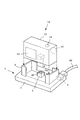
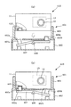
図1は、本発明に係る接続システムを示す外観斜視図である。この接続システムは接続台であるクレードル1と、クレードル1に着脱自在であるとともに、装着状態でクレードル1を介してパーソナルコンピュータ(PC)に接続されることによりPCとの間のデータ通信が可能なデジタルカメラ10とから構成されている。
Hereinafter, an embodiment of the present invention will be described with reference to the drawings.
(First embodiment)
FIG. 1 is an external perspective view showing a connection system according to the present invention. This connection system is detachable from the cradle 1, which is a connection base, and can be connected to a personal computer (PC) via the cradle 1 in a mounted state, thereby enabling data communication with the PC. It comprises a digital camera 10.

クレードル1は、本体2の上部に、上方より装着されたデジタルカメラ10を垂直よりも背面側へ若干寝かせた状態で保持する保持部3が設けられた構造を有している。本体2の背面側には、第1の接続コネクタ4が設けられ、前記保持部3の内側に位置する本体2の上面部分には第2の接続コネクタ5が突出した状態で設けられている。第1の接続コネクタ4には、一端側が図外のPCに接続されている通信ケーブル50の他端が接続されている。第1の接続コネクタ4と第2の接続コネクタ5とは、本体2の内部において互いに対応する端子同士を結線されている。   The cradle 1 has a structure in which a holding unit 3 is provided on the upper part of the main body 2 to hold the digital camera 10 mounted from above in a state where the digital camera 10 is slightly laid on the back side rather than vertically. A first connection connector 4 is provided on the back side of the main body 2, and a second connection connector 5 is provided on the upper surface portion of the main body 2 located inside the holding portion 3 in a protruding state. The first connection connector 4 is connected to the other end of a communication cable 50 whose one end is connected to a PC (not shown). The first connection connector 4 and the second connection connector 5 are connected to each other corresponding terminals inside the main body 2.

デジタルカメラ10は、本体11の正面に撮影レンズ12が、かつ背面に液晶表示器13が設けられ、上面にシャッター釦14が設けられた構造を有している。また本体11の底面にはクレードル1の第2の接続コネクタ5に対応する接続コネクタ15が設けられている。なお、以下の説明においては、上記第2の接続コネクタ5をクレードル側コネクタ、上記接続コネクタ15をカメラ側コネクタという。   The digital camera 10 has a structure in which a photographing lens 12 is provided on the front surface of a main body 11, a liquid crystal display 13 is provided on the back surface, and a shutter button 14 is provided on the upper surface. A connection connector 15 corresponding to the second connection connector 5 of the cradle 1 is provided on the bottom surface of the main body 11. In the following description, the second connection connector 5 is referred to as a cradle side connector, and the connection connector 15 is referred to as a camera side connector.

クレードル側コネクタ5とカメラ側コネクタ15は、デジタルカメラ10をクレードル1に着脱する際、互いに挿抜されるものであり、本実施の形態においてはクレードル側コネクタ5がオス、カメラ側コネクタ15がメスである。また、両コネクタ5,15は、デジタルカメラ10を、液晶表示器13がクレードル1(本体2)の正面側に位置する図1に示した第1の向き、又は撮影レンズ12がクレードル1(本体2)の正面側に位置する第2の向き(図示せず)のどちらに向けても、デジタルカメラ10とクレードル1とを装着可能とする構造を有している。   The cradle-side connector 5 and the camera-side connector 15 are inserted into and removed from each other when the digital camera 10 is attached to or detached from the cradle 1. In this embodiment, the cradle-side connector 5 is a male and the camera-side connector 15 is a female. is there. Further, the connectors 5 and 15 have the digital camera 10 in the first direction shown in FIG. 1 where the liquid crystal display 13 is located on the front side of the cradle 1 (main body 2), or the photographing lens 12 is in the cradle 1 (main body). The digital camera 10 and the cradle 1 can be mounted in either of the second directions (not shown) located on the front side of 2).

すなわち、クレードル側コネクタ5がクレードル1の保持部3の中央部に配置され、かつカメラ側コネクタ15がデジタルカメラ10の本体11の底面中央部に配置されている。さらにクレードル側コネクタ5には、本体2の正面側と背面側とに位置して、各々が複数の接続端子からなる端子列5a,5bが互いに平行して設けられている。双方の端子列5a,5bの一方側と他方側とは各接続端子の配置順が逆順であるとともに、双方が、それらと対応する前記第1の接続コネクタ4が有する複数の接続端子とそれぞれ結線されている。他方、カメラ側コネクタ15には、上記双方の端子列5a,5bのいずれか一方側のみに接続される複数の接続端子(図示せず)が設けられている。   That is, the cradle-side connector 5 is disposed at the center of the holding unit 3 of the cradle 1, and the camera-side connector 15 is disposed at the center of the bottom surface of the main body 11 of the digital camera 10. Further, the cradle-side connector 5 is provided with terminal rows 5a and 5b, each of which is located on the front side and the back side of the main body 2, and each includes a plurality of connection terminals. The arrangement order of the connection terminals on the one side and the other side of both the terminal rows 5a and 5b is reverse, and both are connected to the plurality of connection terminals of the first connection connector 4 corresponding to them. Has been. On the other hand, the camera-side connector 15 is provided with a plurality of connection terminals (not shown) that are connected to only one of the two terminal rows 5a and 5b.

これにより、クレードル側コネクタ5とカメラ側コネクタ15とは、デジタルカメラ10が前述した第1又は第2のいずれの向きで装着されたときであっても、電気的に接続されるようになっている。さらに、クレードル側コネクタ5と、カメラ側コネクタ15には、データ通信用とは別に、カメラ側コネクタ15の端子群がクレードル側コネクタ5のどちら側の端子列5a,5bと接続されているのかを電気的に検出するための検出用端子が設けられている。   As a result, the cradle-side connector 5 and the camera-side connector 15 are electrically connected even when the digital camera 10 is mounted in either the first or second orientation described above. Yes. Further, the cradle-side connector 5 and the camera-side connector 15 indicate which side of the cradle-side connector 5 the terminal groups 5a and 5b of the cradle-side connector 5 are connected to, separately from data communication. A detection terminal for electrical detection is provided.

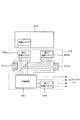
図2は、前述したデジタルカメラ10及びクレードル1の電気的な概略構成を示すブロック図である。デジタルカメラ10は、デジタルカメラ10は、固体撮像素子であるCCD21とCPU22とを有している。CCD21は、図示しないフォーカスレンズ及びズームレンズを介して結像された被写体の光学像を光電変換し、被写体の光学像に応じたアナログの撮像信号を出力する。CPU22は、JPEG方式による画像データの圧縮・伸張を含む各種デジタル信号処理機能を有するとともにデジタルカメラ10の各部を制御する。   FIG. 2 is a block diagram showing a schematic electrical configuration of the digital camera 10 and the cradle 1 described above. The digital camera 10 includes a CCD 21 and a CPU 22 that are solid-state imaging devices. The CCD 21 photoelectrically converts an optical image of a subject formed through a focus lens and a zoom lens (not shown), and outputs an analog imaging signal corresponding to the optical image of the subject. The CPU 22 has various digital signal processing functions including compression / decompression of image data by the JPEG method, and controls each part of the digital camera 10.

CPU22には、CCD21を駆動するTG(Timing Generator)23が接続されており、TG23には、CCD21から出力される撮像信号が入力するユニット回路24が接続されている。ユニット回路24は、を相関二重サンプリングして保持するCDS回路、その撮像信号を増幅するゲイン調整アンプ(AGC)、増幅後の撮像信号をデジタル信号に変換するA/D変換器(AD)から構成されており、CCD21の出力信号はユニット回路24を経てデジタル信号としてCPU22に送られる。   A TG (Timing Generator) 23 that drives the CCD 21 is connected to the CPU 22, and a unit circuit 24 to which an imaging signal output from the CCD 21 is input is connected to the TG 23. The unit circuit 24 includes a CDS circuit that performs correlated double sampling and holds, a gain adjustment amplifier (AGC) that amplifies the imaging signal, and an A / D converter (AD) that converts the amplified imaging signal into a digital signal. The output signal of the CCD 21 is sent to the CPU 22 as a digital signal through the unit circuit 24.

また、CPU22には、表示装置25、キー入力部26、ROM27、DRAM28、内蔵画像メモリ29、入出力インターフェイス30が接続されている。DRAM28は、CCD21により撮像されデジタル化された画像データを一時記憶するバッファであるとともに、CPU22のワーキングメモリとして使用される。DRAM28に一時記憶された画像データは圧縮され、最終的には内蔵画像メモリ29に記録される。表示装置25は前記液晶表示器13とその駆動回路とを含み、撮影待機モード等においては、CCD21によって撮像された被写体画像をスルー画像として表示し、再生モードでは、内蔵画像メモリ29に記録されている画像を表示する。キー入力部26は、前記シャッター釦14や、図示しない電源キー、モード選択キー等の複数の操作キーを含み、使用者によるキー操作に応じたキー入力信号をCPU22に出力する。   In addition, a display device 25, a key input unit 26, a ROM 27, a DRAM 28, a built-in image memory 29, and an input / output interface 30 are connected to the CPU 22. The DRAM 28 is a buffer that temporarily stores image data picked up by the CCD 21 and digitized, and is used as a working memory of the CPU 22. The image data temporarily stored in the DRAM 28 is compressed and finally recorded in the built-in image memory 29. The display device 25 includes the liquid crystal display 13 and its drive circuit. In the shooting standby mode or the like, the subject image captured by the CCD 21 is displayed as a through image, and in the playback mode, it is recorded in the built-in image memory 29. Display the image. The key input unit 26 includes a plurality of operation keys such as the shutter button 14, a power key (not shown), a mode selection key, and the like, and outputs a key input signal corresponding to the key operation by the user to the CPU 22.

入出力インターフェイス30には前記接続コネクタ(カメラ側コネクタ)15が接続されており、入出力インターフェイス30は、CPU22の制御に基づき前記クレードル1を介して接続されたPCとの間でUSBインターフェイス又はRS−232Cインターフェイス等によるデータの送受信を行う。ROM27には、CPU22にデジタルカメラ10の各部を制御させるための制御プログラム、及びCPU22の動作に必要な各種データが記憶されている。そしてCPU22は上記制御プログラムに従い動作することにより、本発明の確認手段、設定手段として機能する。   The input / output interface 30 is connected to the connection connector (camera side connector) 15, and the input / output interface 30 is connected to a PC connected via the cradle 1 based on the control of the CPU 22 with a USB interface or RS. Data is transmitted / received through the -232C interface or the like. The ROM 27 stores a control program for causing the CPU 22 to control each unit of the digital camera 10 and various data necessary for the operation of the CPU 22. And CPU22 functions as a confirmation means and a setting means of this invention by operate | moving according to the said control program.

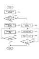
図3は、図1に示したようにクレードル1が通信ケーブル50によってPCと接続されている状態で、電源が投入された状態でデジタルカメラ10がクレードル1に装着されたときの動作を示すフローチャートである。   FIG. 3 is a flowchart showing an operation when the digital camera 10 is mounted on the cradle 1 with the power on when the cradle 1 is connected to the PC via the communication cable 50 as shown in FIG. It is.

デジタルカメラ10においてはクレードル1に装着されると、CPU22が、カメラ側コネクタ15の各端子がクレードル側コネクタ5の前述した端子列5a,5bのいずれの側と接続されたのかを電気的に検出することにより、デジタルカメラ10がクレードル1に対し、前述した第1又は第2のいずれの向きで装着されたのかを確認する(ステップSA1)。   When the digital camera 10 is attached to the cradle 1, the CPU 22 electrically detects which terminal of the camera-side connector 15 is connected to which side of the terminal rows 5 a and 5 b of the cradle-side connector 5. By doing this, it is confirmed whether the digital camera 10 is mounted on the cradle 1 in the first or second orientation described above (step SA1).

ここで、デジタルカメラ10の向きが、液晶表示器13がクレードル1の正面側に位置する向き、すなわち図1に示した第1の向きであったときには(ステップSA2でYES)、CPU22は動作モードを記録画像転送モードに設定し、そのモードでの動作を開始する(ステップSA3)。そして、内蔵画像メモリ29に記録されている画像データ(画像ファィル)を所定の順序で読み出し、それをPCへ転送する(ステップSA4)。これを、全ての画像データの転送が終了するまで続け、それが終了した時点で(ステップSA5でYES)、記録画像転送モードでの動作を終了する。   Here, when the orientation of the digital camera 10 is the orientation in which the liquid crystal display 13 is located on the front side of the cradle 1, that is, the first orientation shown in FIG. 1 (YES in step SA2), the CPU 22 operates in the operation mode. Is set to the recording image transfer mode, and the operation in that mode is started (step SA3). Then, the image data (image file) recorded in the built-in image memory 29 is read in a predetermined order and transferred to the PC (step SA4). This is continued until the transfer of all the image data is completed. When the transfer is completed (YES in step SA5), the operation in the recording image transfer mode is ended.

一方、ステップSA1で確認したデジタルカメラ10の向きが、撮影レンズ12がクレードル1の正面側に位置する向き、すなわち図1とは逆の第2の向きであったときには(ステップSA2でNO)、CPU22は動作モードを所謂PCカメラとして機能するためのPCカメラモードに設定し、そのモードでの動作を開始する(ステップSA6)。そして、CCD21により被写体像を撮像するとともに(ステップSA7)、撮像した画像データを逐次PCへ転送する(ステップSA8)。これを、ユーザーによるデジタルカメラ10側やPC側における所定のキー操作によるモード終了操作があったり、あるいはPC側から送られる終了指示信号を受信するまで続け、モード終了操作等があった時点で(ステップSA9でYES)、PCカメラモードでの動作を終了する。   On the other hand, when the orientation of the digital camera 10 confirmed in step SA1 is the orientation in which the photographing lens 12 is located on the front side of the cradle 1, that is, the second orientation opposite to FIG. 1 (NO in step SA2). The CPU 22 sets the operation mode to a PC camera mode for functioning as a so-called PC camera, and starts operation in that mode (step SA6). Then, the subject image is captured by the CCD 21 (step SA7), and the captured image data is sequentially transferred to the PC (step SA8). This is continued until there is a mode end operation by a predetermined key operation on the digital camera 10 side or PC side by the user, or an end instruction signal sent from the PC side is received. In step SA9, YES), the operation in the PC camera mode is terminated.

したがって、ユーザーは、デジタルカメラ10をクレードル1に装着してPCとの間のデータ通信機能を利用するとき、デジタルカメラ10の向きを選択的に変えるだけで、デジタルカメラ10に所望とする動作モード(記録画像転送モードまたはPCカメラモード)を設定することができる。よって、データ通信機能を利用するとき、そのモード設定を極めて容易に行うことができる。   Therefore, when the user mounts the digital camera 10 on the cradle 1 and uses the data communication function with the PC, the user can select a desired operation mode for the digital camera 10 only by selectively changing the orientation of the digital camera 10. (Recorded image transfer mode or PC camera mode) can be set. Therefore, when the data communication function is used, the mode setting can be performed very easily.

また、本実施の形態においては、クレードル1が保持部3によってデジタルカメラ10を垂直よりも背面側へ若干寝かせた状態で保持する構造であるとともに、デジタルカメラ10の向きと動作モードとの関係が、液晶表示器13をクレードル1の正面側つまりユーザー側へ向けたときには記録画像転送モードとなる一方、撮影レンズ12をクレードル1の正面側へ向けたときにはPCカメラモードとなるように設定されている。このため、記録画像転送モードでは液晶表示器13が若干上向きとなるため動作中における液晶表示器13の表示画面が見やすく、またPCカメラモードでは、撮影レンズ12の光軸が上向きとなるため、撮影に適した状態を容易に確保することができるという利点がある。   Further, in the present embodiment, the cradle 1 is configured to hold the digital camera 10 with the holding unit 3 in a state of being slightly laid down from the vertical side to the back side, and there is a relationship between the orientation of the digital camera 10 and the operation mode. The recording image transfer mode is set when the liquid crystal display 13 is directed to the front side of the cradle 1, that is, the user side, while the PC camera mode is set when the photographing lens 12 is directed to the front side of the cradle 1. . Therefore, the liquid crystal display 13 is slightly upward in the recorded image transfer mode, so that the display screen of the liquid crystal display 13 during operation is easy to see. In the PC camera mode, the optical axis of the photographing lens 12 is upward, so There is an advantage that a state suitable for the above can be easily secured.

なお、本実施の形態では、デジタルカメラ10が、電源が投入された状態でクレードル1へ装着されたとき、前述したように自動的に記録画像転送モード又はPCカメラモードで動作するものとしたが、クレードル1へ装着されたとき、カメラ側コネクタ15がクレードル側コネクタ5に接続されることにより自動的に電源がオン状態となる構成としてもよい。   In the present embodiment, when the digital camera 10 is attached to the cradle 1 with the power on, as described above, it automatically operates in the recorded image transfer mode or the PC camera mode. When mounted on the cradle 1, the camera side connector 15 may be connected to the cradle side connector 5 to automatically turn on the power.

また、本実施の形態では、クレードル1に装着した時の向きに応じて、デジタルカメラ10のデータ通信機能に関する動作モードが選択的に設定されるようにしたが、本発明において選択的に設定される動作モードはデータ通信機能に関する以外の動作モードであってもよい。例えば充電モードと画像データの(PC等への)移動、充電モードとデジタルカメラの動作内容等をユーザーの好みに応じて設定するための設定(カスタマイズ)、セルフタイマー撮影と画像データの移動、記録画像の表示と画像データの移動、音楽データ再生又は音楽データの(PC等への)転送と画像データの転送又は記録画像の表示などのように、デジタルカメラのいかなる種類の動作に関するものであっても構わない。
In the present embodiment, the operation mode related to the data communication function of the digital camera 10 is selectively set according to the orientation when the cradle 1 is mounted. However, the operation mode is selectively set in the present invention. The operation mode may be an operation mode other than the data communication function. For example, charging mode and transfer of image data (to PC etc.), setting (customization) to set charging mode and operation contents of digital camera according to user's preference, self-timer shooting and transfer and recording of image data It relates to any kind of operation of a digital camera, such as displaying images and moving image data, playing music data or transferring music data (to a PC etc.) and transferring image data or displaying recorded images. It doesn't matter.

(第2の実施の形態)
図4は、第2の実施の形態に係る接続システムを示す外観斜視図である。この接続システムも、クレードル101と、クレードル101に着脱自在であるとともに、クレードル101を介してPCとの間のデータ通信が可能なデジタルカメラ10とから構成されている。
(Second Embodiment)
FIG. 4 is an external perspective view showing the connection system according to the second embodiment. This connection system also includes a cradle 101 and a digital camera 10 that can be attached to and detached from the cradle 101 and can communicate data with a PC via the cradle 101.

クレードル101は、上面に円形の開口部102aが設けられた本体102の内部に、円板状の回転台106が回転自在に取り付けられた構造を有している。前記回転台106は本発明の可動保持部であって、その上面には、本体102の開口部102aにて起立するとともに、上方より装着されたデジタルカメラ10を保持する保持部103が設けられている。回転台106は、本体102に対して水平方向に180度以上の回転を許容されており、その外周部には押圧突起106aが設けられている。   The cradle 101 has a structure in which a disk-shaped turntable 106 is rotatably mounted inside a main body 102 having a circular opening 102a on the upper surface. The turntable 106 is a movable holding portion of the present invention, and a holding portion 103 for holding the digital camera 10 mounted from above is provided on the upper surface of the rotating stand 106 while standing at the opening 102a of the main body 102. Yes. The turntable 106 is allowed to rotate 180 degrees or more in the horizontal direction with respect to the main body 102, and a pressing protrusion 106 a is provided on the outer peripheral portion thereof.

前記本体102の背面側には第1の接続コネクタ104が設けられ、前記回転台106には、前記保持部103の内側に位置する上面部分に突出する第2の接続コネクタ105が設けられており、第1及び第2の接続コネクタ104,105は、本体102の内部において互いに対応する端子同士を結線されている。一方、図5に示したように第2の接続コネクタ105には、データ通信用の端子とは別に前記回転台106の回転位置の検出に使用される検出用端子105aが設けられており、その検出用端子105aと所定のデータ通信用端子105bとの間を短絡、開放する切替スイッチ107が第1の接続コネクタ104に一体的に設けられている。なお、切替スイッチ107は、回転台106が所定の位置まで回転した状態(図4に示した状態)で押圧突起106aに押圧されることによってオフ状態からオン状態に動作するマイクロスイッチである。   A first connection connector 104 is provided on the back side of the main body 102, and a second connection connector 105 protruding from an upper surface portion located inside the holding portion 103 is provided on the turntable 106. The first and second connection connectors 104 and 105 have corresponding terminals connected to each other inside the main body 102. On the other hand, as shown in FIG. 5, the second connection connector 105 is provided with a detection terminal 105a used for detecting the rotational position of the turntable 106, in addition to the data communication terminal. A changeover switch 107 that short-circuits and opens between the detection terminal 105 a and a predetermined data communication terminal 105 b is provided integrally with the first connection connector 104. The changeover switch 107 is a micro switch that operates from an off state to an on state when pressed by the pressing protrusion 106a in a state in which the turntable 106 is rotated to a predetermined position (the state illustrated in FIG. 4).

なお、デジタルカメラ10の外観構造及び電気的構成については、第1の実施の形態において説明したものと同様である。   The external structure and electrical configuration of the digital camera 10 are the same as those described in the first embodiment.

そして、本実施の形態において、デジタルカメラ10は、電源が投入された状態で、通信ケーブル50によりPCと接続されているクレードル101に装着されると以下のように動作する。   In the present embodiment, the digital camera 10 operates as follows when attached to the cradle 101 connected to the PC via the communication cable 50 with the power turned on.

まず、デジタルカメラ10は、接続コネクタ15が接続されたクレードル101の第2の接続コネクタ105を介して前述した切替スイッチ107のオンオフ状態を電気的に検出することにより、デジタルカメラ10におけるクレードル101の本体102に対する向きを確認する。そして、切替スイッチ107がオン状態であって、液晶表示器13がクレードル101の正面側に位置する向き、すなわち図4に示した向きであったときには、図3のステップSA3〜SA5と同様の動作により、自動的に記録画像転送モードに移行し、内蔵画像メモリ29に記録されている全ての画像データ(画像ファィル)をPCへ転送する。また、切替スイッチ107がオフ状態であって、デジタルカメラ10の向きが、例えば液晶表示器13がクレードル101の背面側に位置する向きであったときには、図3のステップSA6〜SA9と同様の動作により、自動的にPCカメラモードに移行するとともに、撮像した画像データをPCへ逐次転送し、それをモード終了操作等があるまで続ける。   First, the digital camera 10 electrically detects the on / off state of the switch 107 described above via the second connection connector 105 of the cradle 101 to which the connection connector 15 is connected, so that the cradle 101 of the digital camera 10 is detected. The orientation with respect to the main body 102 is confirmed. When the changeover switch 107 is in the on state and the liquid crystal display 13 is in the direction on the front side of the cradle 101, that is, in the direction shown in FIG. 4, the same operation as steps SA3 to SA5 in FIG. Thus, the recording image transfer mode is automatically entered, and all the image data (image files) recorded in the built-in image memory 29 are transferred to the PC. Further, when the changeover switch 107 is in the OFF state and the orientation of the digital camera 10 is, for example, the orientation in which the liquid crystal display 13 is positioned on the back side of the cradle 101, the same operation as steps SA6 to SA9 in FIG. Thus, the mode automatically shifts to the PC camera mode, and the captured image data is sequentially transferred to the PC, and this is continued until a mode end operation or the like is performed.

したがって、ユーザーは、デジタルカメラ10をクレードル101に装着してPCとの間のデータ通信機能を利用するとき、クレードル101の回転台106を回転させることによってデジタルカメラ10の本体102に対する向きを選択的に変えるだけで、デジタルカメラ10に所望とする動作モード(記録画像転送モードまたはPCカメラモード)を設定することができる。よって、データ通信機能を利用するとき、そのモード設定を極めて容易に行うことができる。また、第1の実施の形態のシステムと比較すると、デジタルカメラ10をクレードル101に装着したままで動作モードの切り替えが可能である、という利点がある。   Therefore, when the user mounts the digital camera 10 on the cradle 101 and uses the data communication function with the PC, the user selectively selects the orientation of the digital camera 10 relative to the main body 102 by rotating the turntable 106 of the cradle 101. The desired operation mode (recorded image transfer mode or PC camera mode) can be set in the digital camera 10 simply by changing to. Therefore, when the data communication function is used, the mode setting can be performed very easily. Further, compared with the system of the first embodiment, there is an advantage that the operation mode can be switched while the digital camera 10 is mounted on the cradle 101.

さらに、例えばクレードル101の本体102側に、回転台106の押圧突起106aの複数ヶ所の回転位置を検出するスイッチを設け、使用時には、クレードル101の本体102に対する複数の向きをデジタルカメラ10に確認させる構成とすれば、デジタルカメラ10が、データ通信機能に関する動作モードを3つ以上有する場合に、それら3つ以上の動作モードを、上記本体102に対する向きに応じて選択的に設定することも可能となる。   Further, for example, a switch for detecting a plurality of rotational positions of the pressing projections 106a of the turntable 106 is provided on the main body 102 side of the cradle 101 so that the digital camera 10 can confirm a plurality of directions of the cradle 101 with respect to the main body 102 at the time of use. With this configuration, when the digital camera 10 has three or more operation modes related to the data communication function, the three or more operation modes can be selectively set according to the orientation with respect to the main body 102. Become.

なお、本実施の形態においても、デジタルカメラ10が、電源が投入された状態でクレードル101へ装着されたとき、自動的に記録画像転送モード又はPCカメラモードで動作するものとしたが、クレードル101へ装着されたとき、カメラ側コネクタ15がクレードル側コネクタ105に接続されることにより自動的に電源がオン状態となる構成としてもよい。   Also in this embodiment, when the digital camera 10 is mounted on the cradle 101 with the power turned on, the digital camera 10 automatically operates in the recorded image transfer mode or the PC camera mode. When the camera-side connector 15 is attached to the cradle-side connector 105, the power may be automatically turned on.

また、本実施の形態では、デジタルカメラ10の、回転台106の回転位置に応じた向きに応じて、デジタルカメラ10のデータ通信機能に関する動作モードが選択的に設定されるようにしたが、第1の実施の形態において説明したように、選択的に設定される動作モードはデータ通信機能に関する以外の動作モードであってもよい。
In the present embodiment, the operation mode related to the data communication function of the digital camera 10 is selectively set according to the orientation of the digital camera 10 according to the rotation position of the turntable 106. As described in the first embodiment, the operation mode selectively set may be an operation mode other than the data communication function.

(第3の実施の形態)
図6は、第3の実施の形態に係る接続システムを示す外観斜視図である。この接続システムも、クレードル201と、クレードル201に着脱自在であるとともに、クレードル201を介してPCとの間のデータ通信が可能なデジタルカメラ210とから構成されている。
(Third embodiment)
FIG. 6 is an external perspective view showing a connection system according to the third embodiment. This connection system also includes a cradle 201 and a digital camera 210 that is detachably attached to the cradle 201 and capable of data communication with a PC via the cradle 201.

クレードル201は、第1の実施の形態で説明したものとほぼ同様の構成を有するものであり、前者との構成上の違いは、前記保持部3の内側に設けられている第2の接続コネクタ205が、データ通信用の端子群を1組だけ備えている点のみである。   The cradle 201 has substantially the same configuration as that described in the first embodiment, and the difference in configuration from the former is the second connection connector provided inside the holding portion 3. 205 is only provided with one set of terminals for data communication.

また、本実施の形態におけるデジタルカメラ210は、第1及び第2の実施の形態で説明したものとは異なり、本体11の一方の側部に、両側部の中心を通る軸Oを中心に180度以上(例えば270度)の角度範囲で正面側と背面側とに回動自在な可動部211が設けられ、その可動部211に前記撮影レンズ12やCCD21が設けられている。また、本体11の底面に設けられている接続コネクタ215は、クレードル201の第2の接続コネクタ205に対応しており、本体11の背面側(液晶表示器13が位置する側)が、図6に示したようにクレードル201の正面側を向いた状態で上記第2の接続コネクタ205に接続可能となっている。なお、以下の説明においては、上記第2の接続コネクタ205をクレードル側コネクタ、上記接続コネクタ215をカメラ側コネクタという。   Also, the digital camera 210 in the present embodiment is different from those described in the first and second embodiments in that it is 180 around the axis O passing through the center of both sides on one side of the main body 11. A movable part 211 is provided that is rotatable on the front side and the back side within an angle range of more than 80 degrees (for example, 270 degrees), and the photographing lens 12 and the CCD 21 are provided on the movable part 211. Further, the connection connector 215 provided on the bottom surface of the main body 11 corresponds to the second connection connector 205 of the cradle 201, and the back side of the main body 11 (the side where the liquid crystal display 13 is located) is shown in FIG. As shown in FIG. 5, the second connection connector 205 can be connected with the front side of the cradle 201 facing. In the following description, the second connection connector 205 is referred to as a cradle side connector, and the connection connector 215 is referred to as a camera side connector.

さらに、デジタルカメラ210は、図7に示したように撮影方向検出部212を有している。撮影方向検出部212は、撮影レンズ12の向きを検出するためのものであって、前記可動部211が本体11の上面より背面側(液晶表示器13が位置する側)へ回動しているときオン状態となる検出スイッチ(図示せず)、及びその動作状態に基づく撮影方向を示す検出信号をCPU22へ送る回路とから構成されている。なお、これ以外の構成については、第1及び第2の実施の形態で説明したものと同様である。   Further, the digital camera 210 has a photographing direction detection unit 212 as shown in FIG. The photographing direction detection unit 212 is for detecting the direction of the photographing lens 12, and the movable unit 211 is rotated from the upper surface of the main body 11 to the back side (the side where the liquid crystal display 13 is located). A detection switch (not shown) that is sometimes turned on, and a circuit that sends a detection signal indicating the photographing direction based on the operation state to the CPU 22. Other configurations are the same as those described in the first and second embodiments.

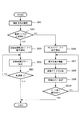
そして、本実施の形態において、デジタルカメラ210は、電源が投入された状態で、通信ケーブル50によりPCと接続されているクレードル201に装着されると以下のように動作する。図8は、そのときの動作を示すフローチャートである。   In this embodiment, when the digital camera 210 is attached to the cradle 201 connected to the PC via the communication cable 50 with the power turned on, the digital camera 210 operates as follows. FIG. 8 is a flowchart showing the operation at that time.

デジタルカメラ210は、カメラ側コネクタ215がクレードル側コネクタ205と接続されると、まず撮影方向検出部212が出力する検出信号に基づき、撮影レンズ12の向き(撮影方向)が正面側であるか否かを確認する(ステップSB1)。そして、前記撮影方向検出部212の検出スイッチがオフ状態であって、撮影レンズ12が本体11の正面側、つまりクレードル201の背面側であったときには(ステップSB2でYES)、CPU22は動作モードを記録画像転送モードに設定し、そのモードでの動作を開始する(ステップSB3)。そして、内蔵画像メモリ29に記録されている画像データ(画像ファィル)を所定の順序で読み出し、それをPCへ転送する(ステップSB4)。これを、全ての画像データの転送が終了するまで続け、それが終了した時点で(ステップSB5でYES)、記録画像転送モードでの動作を終了する。   In the digital camera 210, when the camera-side connector 215 is connected to the cradle-side connector 205, first, based on the detection signal output from the shooting direction detection unit 212, whether the direction of the shooting lens 12 (shooting direction) is the front side or not. (Step SB1). When the detection switch of the shooting direction detection unit 212 is in the OFF state and the shooting lens 12 is on the front side of the main body 11, that is, on the back side of the cradle 201 (YES in step SB2), the CPU 22 changes the operation mode. The recording image transfer mode is set, and the operation in that mode is started (step SB3). Then, the image data (image file) recorded in the built-in image memory 29 is read in a predetermined order and transferred to the PC (step SB4). This is continued until the transfer of all the image data is completed. When the transfer is completed (YES in step SB5), the operation in the recording image transfer mode is ended.

一方、ステップSB1で確認した撮影レンズ12の向きが本体11の背面側でって、例えば図6に示したようにクレードル201の正面画側であったときには(ステップSB2でNO)、CPU22は動作モードを所謂PCカメラとして機能するためのPCカメラモードに設定し、そのモードでの動作を開始する(ステップSB6)。そして、CCD21により被写体像を撮像し(ステップSB7)、撮像した画像をいったん上下に反転(180度回転)した後(ステップSB8)、その画像データを逐次PCへ転送する(ステップSB9)。これを、ユーザーによるデジタルカメラ210側やPC側における所定のキー操作によるモード終了操作があったり、あるいはPC側から送られる終了指示信号を受信するまで続け、モード終了操作等があった時点で(ステップSB10でYES)、PCカメラモードでの動作を終了する。   On the other hand, when the direction of the photographing lens 12 confirmed in step SB1 is the back side of the main body 11, for example, the front image side of the cradle 201 as shown in FIG. 6 (NO in step SB2), the CPU 22 operates. The mode is set to a PC camera mode for functioning as a so-called PC camera, and the operation in that mode is started (step SB6). Then, a subject image is picked up by the CCD 21 (step SB7), the picked-up image is once inverted upside down (rotated 180 degrees) (step SB8), and the image data is sequentially transferred to the PC (step SB9). This is continued until there is a mode end operation by a predetermined key operation on the digital camera 210 side or PC side by the user, or an end instruction signal sent from the PC side is received. In step SB10, YES), the operation in the PC camera mode is terminated.

したがって、ユーザーは、デジタルカメラ210をクレードル201に装着してPCとの間のデータ通信機能を利用するとき、撮影レンズ12が設けられている可動部211(撮影レンズ12)の向きを選択的に変えるだけで、デジタルカメラ210に所望とする動作モード(記録画像転送モードまたはPCカメラモード)を設定することができる。よって、データ通信機能を利用するとき、そのモード設定を極めて容易に行うことができる。また、第2の実施の形態と同様に、デジタルカメラ210をクレードル201に装着したままで動作モードの切り替えが可能である、という利点がある。   Therefore, when the user mounts the digital camera 210 on the cradle 201 and uses the data communication function with the PC, the user selectively selects the direction of the movable portion 211 (shooting lens 12) provided with the shooting lens 12. The desired operation mode (recorded image transfer mode or PC camera mode) can be set in the digital camera 210 simply by changing. Therefore, when the data communication function is used, the mode setting can be performed very easily. Further, similarly to the second embodiment, there is an advantage that the operation mode can be switched while the digital camera 210 is mounted on the cradle 201.

さらに、デジタルカメラ210に、可動部211(撮影レンズ12)の複数の向きを(回転位置)を検出するスイッチを設け、使用時には、クレードル201に対する可動部211の複数の向きを確認させる構成とすれば、デジタルカメラ210が、データ通信機能に関する動作モードを3つ以上有する場合に、それら3つ以上の動作モードを、可動部211の向きに応じて選択的に設定することも可能となる。   Further, the digital camera 210 is provided with a switch for detecting a plurality of orientations (rotational positions) of the movable portion 211 (photographing lens 12) so that the plurality of orientations of the movable portion 211 with respect to the cradle 201 can be confirmed during use. For example, when the digital camera 210 has three or more operation modes related to the data communication function, the three or more operation modes can be selectively set according to the direction of the movable portion 211.

なお、本実施の形態においても、デジタルカメラ210が、電源が投入された状態でクレードル201へ装着されたとき、自動的に記録画像転送モード又はPCカメラモードで動作するものとしたが、クレードル201へ装着されたとき、カメラ側コネクタ215がクレードル側コネクタ205に接続されることにより自動的に電源がオン状態となる構成としてもよい。   Also in this embodiment, when the digital camera 210 is attached to the cradle 201 with the power turned on, the digital camera 210 automatically operates in the recorded image transfer mode or the PC camera mode. When the camera-side connector 215 is connected to the cradle-side connector 205, the power may be automatically turned on.

また、本実施の形態では、デジタルカメラ210の可動部211の向きに応じて、デジタルカメラ210のデータ通信機能に関する動作モードが選択的に設定されるようにしたが、第1及び第2の実施の形態において説明したように、選択的に設定される動作モードはデータ通信機能に関する以外の動作モードであってもよい。
In the present embodiment, the operation mode related to the data communication function of the digital camera 210 is selectively set according to the direction of the movable portion 211 of the digital camera 210. However, the first and second embodiments are described. As described in the embodiment, the selectively set operation mode may be an operation mode other than the data communication function.

(第4の実施の形態)
本実施の形態は、前述した第1の実施の形態で説明したクレードル1を介してデジタルカメラ10との間でデータ通信を行い、本発明のデータ処理装置として機能するパーソナルコンピュータ(PC)に関するものである。
(Fourth embodiment)
The present embodiment relates to a personal computer (PC) that performs data communication with the digital camera 10 via the cradle 1 described in the first embodiment and functions as the data processing apparatus of the present invention. It is.

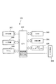
図9は、本実施の形態のPC301の概略構成を示すブロック図である。パーソナルコンピュータ301は、主としてCPU302、RAM303、記憶装置304、入出力インターフェイス305、本体に接続されたキーボードやマウス等の入力装置306、LCDやCRTである表示装置307、電話回線を介してインターネットに接続するためのモデム308を有している。   FIG. 9 is a block diagram illustrating a schematic configuration of the PC 301 of the present embodiment. The personal computer 301 is mainly connected to the Internet through a CPU 302, a RAM 303, a storage device 304, an input / output interface 305, an input device 306 such as a keyboard and a mouse connected to the main body, a display device 307 such as an LCD or CRT, and a telephone line. A modem 308 is provided.

入出力インターフェイス305には、図1に示した前記通信ケーブル50の図示しない他端が接続される接続コネクタ(PC側コネクタ)309が接続されており、入出力インターフェイス305は、CPU302の制御に基づき前記クレードル1を介して接続されたデジタルカメラとの間でUSBインターフェイス又はRS−232Cインターフェイス等によるデータの送受信を行う。記憶装置304は記憶容量の比較的大きなハードディスク等である。   A connection connector (PC-side connector) 309 to which the other end of the communication cable 50 shown in FIG. 1 is connected is connected to the input / output interface 305, and the input / output interface 305 is based on the control of the CPU 302. Data is transmitted / received to / from a digital camera connected via the cradle 1 by a USB interface or an RS-232C interface. The storage device 304 is a hard disk or the like having a relatively large storage capacity.

また、記憶装置304には、任意のOS(オペレーティングシステム)と、複数種のアプリケーションプログラムが格納されており、本実施の形態では、前記クレードル1に付属して提供されたクレードル連携プログラム、画像データ取り込み用プログラムと、PC301に、デジタルカメラ10をPCカメラ(又はWebカメラ)として使用して、デジタルカメラ10が撮影した画像をインターネット上の所定のサイト、例えばユーザーのホームページに逐次アップロードするための画像アップロード用プログラムが格納されている。そして、本実施の形態では、CPU302が前記クレードル連携プログラムに従い動作することにより、本発明の確認手段、設定手段として機能する。   The storage device 304 stores an arbitrary OS (operating system) and a plurality of types of application programs. In this embodiment, the cradle cooperation program and image data provided with the cradle 1 are provided. An image for sequentially uploading an image taken by the digital camera 10 to a predetermined site on the Internet, for example, a user's home page, using the digital camera 10 as a PC camera (or Web camera) on the PC 301 Stores the upload program. In this embodiment, the CPU 302 operates according to the cradle cooperation program, thereby functioning as a confirmation unit and a setting unit of the present invention.

次に、前記PC301にクレードル1が接続されるとともに、その状態でクレードル1にデジタルカメラ10が装着されたときの、PC301の本発明に係る動作を図10のフローチャートに従って説明する。なお、ここでは、PC301が、前述したクレードル連携プログラムが常駐した状態で起動されており、かつクレードル連携プログラムには、後述するように起動させるプログラムが事前に設定されているものとする。   Next, the operation of the PC 301 according to the present invention when the cradle 1 is connected to the PC 301 and the digital camera 10 is mounted on the cradle 1 in this state will be described with reference to the flowchart of FIG. Here, it is assumed that the PC 301 is activated in a state where the above-described cradle cooperation program is resident, and a program to be activated is set in advance in the cradle cooperation program as described later.

PC301は、デジタルカメラ10がクレードル1に装着されると、CPU302は、カメラ側コネクタ15の各端子がクレードル側コネクタ5の前述した端子列5a,5bのいずれの側と接続されたのかを電気的に検出することにより、デジタルカメラ10がクレードル1に対し、前述した前述した第1の向き(液晶表示器13がクレードル1の正面側に位置する図1の向き)と、第2の向き(撮影レンズ12がクレードル1の正面側に位置する向き)のいずれの向きで装着されたのかを確認する(ステップSC1)。   When the digital camera 10 is mounted on the cradle 1, the PC 301 electrically determines which terminal of the camera-side connector 15 is connected to which side of the terminal rows 5 a and 5 b of the cradle-side connector 5. , The digital camera 10 with respect to the cradle 1 described above in the first direction described above (the liquid crystal display 13 is located on the front side of the cradle 1) and the second direction (photographing). It is confirmed in which direction the lens 12 is mounted (the direction in which the lens 12 is located on the front side of the cradle 1) (step SC1).

ここで、デジタルカメラ10の向きが、第1の向きであったときには(ステップAC2でYES)、CPU302は画像データ取り込み用プログラムを起動するとともに、デジタルカメラ10から転送される画像データを記憶装置304の所定場所に記憶する動作を開始する(ステップAC3)。以後、転送された画像データを順次記憶する動作を行い(ステップAC4)、デジタルカメラ10から、全ての画像データの転送が終了した旨の信号を受信した時点で(ステップAC5でYES)、画像データ取り込み用プログラムに従った動作を終了する。   Here, when the orientation of the digital camera 10 is the first orientation (YES in step AC2), the CPU 302 activates the image data capturing program and stores the image data transferred from the digital camera 10 in the storage device 304. The operation of storing in the predetermined place is started (step AC3). Thereafter, an operation of sequentially storing the transferred image data is performed (step AC4), and when a signal indicating that the transfer of all the image data has been completed is received from the digital camera 10 (YES in step AC5), the image data Ends the operation according to the import program.

一方、ステップAC1で確認したデジタルカメラ10の向きが、撮影レンズ12が第2の向きであったときには(ステップAC2でNO)、CPU302は画像アップロード用プログラムを起動する(ステップSC6)。そして、デジタルカメラ10から転送されてくる画像データを逐次受信しながら、転送されてくる画像データをアップロードするための処理、例えばユーザーの操作に応じたモデム308を介してのインターネットへの接続動作や、接続後における実際の画像データのアップロードを行う(ステップSC7)。そして、ユーザーによる動作終了操作があった時点で(ステップAC8でYES)、画像アップロード用プログラムを終了する。   On the other hand, when the direction of the digital camera 10 confirmed in step AC1 is the second direction of the photographing lens 12 (NO in step AC2), the CPU 302 activates the image upload program (step SC6). A process for uploading the transferred image data while sequentially receiving the image data transferred from the digital camera 10, for example, an operation for connecting to the Internet via the modem 308 according to the user's operation, The actual image data after connection is uploaded (step SC7). Then, when there is an operation end operation by the user (YES in step AC8), the image upload program is ended.

したがって、本実施の形態によれば、ユーザーはクレードル1に装着するデジタルカメラ10の向きを選択的に変えるだけで、PC301に、画像データの取り込み動作と、画像データのアップロード準備とを自動的に行わせることができる。つまり、PC301においてデジタルカメラ10との間でのデータ通信機能を利用するとき、その作業を容易に行うことができる。   Therefore, according to the present embodiment, the user can automatically perform the image data capturing operation and the image data upload preparation to the PC 301 only by selectively changing the orientation of the digital camera 10 attached to the cradle 1. Can be done. That is, when using the data communication function with the digital camera 10 in the PC 301, the work can be easily performed.

なお、本実施の形態では、PC301に、画像データの取り込み動作と、画像データのアップロード準備とを選択的に行わせることができるようにした場合について説明したが、前述したアプリケーションプログラムとは別のプログラムを記憶装置304に格納しておき、PC301に、上記とは異なるデータ通信機能に関する動作を行わせるようにしてもよい。例えば記憶装置304の所定の場所に記憶されている画像データ等のデータを、PC301からデジタルカメラ10へ転送し、デジタルカメラ10の内蔵画像メモリ29等に記録させる動作を行わせるようにしてもよい。また、本実施の形態では、PC301に第1の実施の形態で説明したクレードル1を使用する場合について説明したが、当然のように、第2及び第3の実施の形態で説明したクレードル101,201等の他のクレードルを使用するものとしてもよい。   In the present embodiment, the case has been described in which the PC 301 can selectively perform the image data capturing operation and the image data upload preparation. However, this is different from the application program described above. The program may be stored in the storage device 304, and the PC 301 may be caused to perform an operation related to a data communication function different from the above. For example, data such as image data stored in a predetermined location of the storage device 304 may be transferred from the PC 301 to the digital camera 10 and recorded in the built-in image memory 29 of the digital camera 10 or the like. . In the present embodiment, the case where the cradle 1 described in the first embodiment is used for the PC 301 has been described. As a matter of course, the cradle 101 described in the second and third embodiments, Other cradle such as 201 may be used.

また、本実施の形態においては、デジタルカメラ10が、クレードル1に装着されたときの向きを確認し、自ら動作モードを記録画像転送モード又はPCカメラモードに設定する機能を有するものであって、PC301が、クレードル1に装着されたデジタルカメラ10の向きに応じて、起動するアプリケーションプログラムを自動的に設定(選択)するものを説明したが、記憶装置304に本実施の形態とは異なるクレードル連携プログラムを格納しておき、PC301に以下のような動作を行わせるようにしてもよい。   In the present embodiment, the digital camera 10 has a function of confirming the orientation when the digital camera 10 is attached to the cradle 1, and setting the operation mode to the recorded image transfer mode or the PC camera mode. Although the description has been given of the case where the PC 301 automatically sets (selects) an application program to be activated in accordance with the orientation of the digital camera 10 attached to the cradle 1, the cradle cooperation different from that of the present embodiment is performed in the storage device 304. The program may be stored and the PC 301 may be operated as follows.

例えば、前述した動作において、ステップSC3,SC6でデジタルカメラ10の向きに応じたプログラムを起動する前又は後に、デジタルカメラ10にクレードル1を介して、ステップSC1で確認した向きが第1の向きであったときには、動作モードを記録画像転送モードに設定させる要求信号を送信し、かつ第2の向きであったときには、動作モードをPCカメラモードに設定させる要求信号を送信することにより、デジタルカメラ10に向きに応じた動作モードを設定させるようにしてもよい。つまりCPU302と入出力インターフェイス30を本発明の動作要求手段として機能させるようにしてもよい。   For example, in the above-described operation, before or after starting the program corresponding to the orientation of the digital camera 10 in steps SC3 and SC6, the orientation confirmed in step SC1 via the cradle 1 to the digital camera 10 is the first orientation. If there is, the digital camera 10 transmits a request signal for setting the operation mode to the recording image transfer mode, and if it is in the second direction, transmits a request signal for setting the operation mode to the PC camera mode. The operation mode may be set according to the direction. That is, the CPU 302 and the input / output interface 30 may function as the operation request unit of the present invention.

その場合には、デジタルカメラ10が有するROM27等に、上記の要求信号に応じて動作モードを設定する処理をCPU22に行わせるためのプログラムを別途記憶させておくことにより、本実施の形態と同様の効果を得ることができる。
In that case, a program for causing the CPU 22 to perform processing for setting the operation mode in accordance with the request signal is separately stored in the ROM 27 or the like of the digital camera 10, so that it is the same as the present embodiment. The effect of can be obtained.

(第5の実施の形態)
図11は、第5の実施の形態に係る接続システムを示す外観斜視図である。この接続システムも、クレードル401と着脱自在であるとともに、クレードル401を介してPCとの間のデータ通信が可能なデジタルカメラ410とから構成されている。
(Fifth embodiment)
FIG. 11 is an external perspective view showing a connection system according to the fifth embodiment. This connection system is also composed of a digital camera 410 that is detachable from the cradle 401 and capable of data communication with a PC via the cradle 401.

本実施の形態のクレードル401は、第1の実施の形態で説明したものと同様、本体402の上部には、上方より装着されたデジタルカメラ410を垂直よりも背面側へ若干寝かせた状態で保持する保持部403が設けられている。また、本体402の背面側には第1の接続コネクタ404が設けられており、第1の接続コネクタ404には、一端側が図外のPCに接続されている通信ケーブル50の他端が接続されている。   The cradle 401 according to this embodiment is held at the top of the main body 402 in a state in which the digital camera 410 mounted from above is slightly laid to the back side rather than vertically, like the one described in the first embodiment. A holding unit 403 is provided. Also, a first connection connector 404 is provided on the back side of the main body 402, and the other end of the communication cable 50 whose one end is connected to a PC (not shown) is connected to the first connection connector 404. ing.

一方、実施の形態のクレードル401においては、前記本体402には、前記保持部4003の内側であって、その長手方向の両端側の対称位置に一対の矩形穴402a,402bが設けられている。また、本体402の内部には、図12に示したように、一対の矩形穴402a,402bの中間位置にして支持軸406が設けられている。支持軸406には、その両端が一対の矩形穴402a,402bの直下に位置する長尺状の可動片407が回動自在に取り付けられており、可動片407の両端部には、各々が後述するように第1の接続コネクタ404に接続された二つの第2の接続コネクタ405a,405bがそれぞれ取り付けられている。   On the other hand, in the cradle 401 of the embodiment, the main body 402 is provided with a pair of rectangular holes 402a and 402b at symmetrical positions on both ends in the longitudinal direction inside the holding portion 4003. As shown in FIG. 12, a support shaft 406 is provided inside the main body 402 at an intermediate position between the pair of rectangular holes 402a and 402b. A long movable piece 407 whose both ends are located directly below the pair of rectangular holes 402a and 402b is rotatably attached to the support shaft 406. Each end of the movable piece 407 is described later. In this manner, two second connection connectors 405a and 405b connected to the first connection connector 404 are respectively attached.

可動片407は、支持軸406に支持された長さ方向の中央部分において下向きにやや折曲されており、これにより図12(a)に示したように、一方側の第2の接続コネクタ405aを本体402の上面と面一となる位置まで内部に後退させると、他方側の第2の接続コネクタ405bが上方に開口する矩形穴402bから保持部403の内側表面に突出し、逆に、同図(b)に示したように、他方側の第2の接続コネクタ405bを本体402の上面と面一となる位置まで内部に後退させると、一方側の第2の接続コネクタ405aが、その上方に開口する矩形穴402aから保持部403の内側表面に突出するようになっている。つまり、前記クレードル401においては、可動片407の両端に取り付けられた二つの第2の接続コネクタ405a,405bが、支持軸406を支点としたシーソー構造によって、一方側が上方から押されると他方側が自動的に保持部403の内側表面に突出する構成となっている。   The movable piece 407 is slightly bent downward at the central portion in the length direction supported by the support shaft 406, and as a result, as shown in FIG. Is retracted inward to a position that is flush with the upper surface of the main body 402, the second connecting connector 405b on the other side protrudes from the rectangular hole 402b that opens upward to the inner surface of the holding portion 403, and conversely, FIG. As shown in (b), when the second connection connector 405b on the other side is retracted to a position where it is flush with the upper surface of the main body 402, the second connection connector 405a on one side is moved upward. The rectangular hole 402a that opens is projected to the inner surface of the holding portion 403. That is, in the cradle 401, when the two second connection connectors 405a and 405b attached to both ends of the movable piece 407 are pressed from the upper side by the seesaw structure with the support shaft 406 as a fulcrum, the other side is automatically In particular, the structure protrudes from the inner surface of the holding portion 403.

また、図13は、前記クレードル401の電気的構成の概略を示す図であり、上記二つの第2の接続コネクタ405a,405bは、それぞれが「1」〜「n」番の複数の端子を有するとともに、「n」番の検出用端子を除いて、データ通信用及び給電用の互いに対応する複数の端子同士を結線された状態で回路基板501に接続され、この回路基板501を介して前記第1の接続コネクタ404に接続されている。なお、回路基板500には、二つの第2の接続コネクタ405a,405bのいずれかを介してデジタルカメラ410へ電源を供給するためのACアダプタが接続されている。   FIG. 13 is a diagram showing an outline of the electrical configuration of the cradle 401. Each of the two second connection connectors 405a and 405b has a plurality of terminals “1” to “n”. At the same time, except for the “n” number detection terminal, a plurality of corresponding terminals for data communication and power feeding are connected to the circuit board 501 and connected to the circuit board 501 through the circuit board 501. 1 connection connector 404. The circuit board 500 is connected to an AC adapter for supplying power to the digital camera 410 via one of the two second connection connectors 405a and 405b.

そして、二つの第2の接続コネクタ405a,405bは、各々が有する前記検出用端子(「n」番の端子)を、互いに異なる番号の他の端子(本実施の形態ではデータ通信用の端子)にそれぞれ接続されるとともに、本体402において各接続端子の配置順が逆順となる状態で前記可動片407に取り付けられている。   The two second connection connectors 405a and 405b have the detection terminals ("n" number terminals) included in each of the two other connection terminals (data communication terminals in the present embodiment) different from each other. Are connected to the movable piece 407 in the state where the arrangement order of the connection terminals in the main body 402 is reversed.

一方、本実施の形態におけるデジタルカメラ410は、第1及び第2の形態で説明したものと同様、本体11の正面に撮影レンズ12が、かつ背面に液晶表示器13が設けられ、上面にシャッター釦14が設けられるとともに、本体11の底面にはメス型の接続コネクタ415が設けられた構造を有している。   On the other hand, the digital camera 410 according to the present embodiment is provided with a photographing lens 12 on the front surface of the main body 11, a liquid crystal display 13 on the back surface, and a shutter on the upper surface, as described in the first and second embodiments. A button 14 is provided, and a female connection connector 415 is provided on the bottom surface of the main body 11.

但し、本実施の形態のデジタルカメラ410にあっては、接続コネクタ415が本体11の幅方向の一方側に寄った位置、つまり左右非対称の位置に設けられており、その位置が、前記クレードル401設けられている一対の矩形穴402a,402bに対応した位置となっている。すなわち接続コネクタ415は、デジタルカメラ410が、その液晶表示器13がクレードル401(本体402)の正面側に位置する第1の向き(図11参照)でクレードル401に装着されたときには一方の矩形穴402bの直上に位置し、かつ撮影レンズ12がクレードル401(本体402)の正面側に位置する第2の向き(図12参照)でクレードル401に装着されたときには他方の矩形穴402aの直上に位置するようになっている。   However, in the digital camera 410 according to the present embodiment, the connection connector 415 is provided at a position close to one side in the width direction of the main body 11, that is, at a left-right asymmetric position. The position corresponds to the pair of rectangular holes 402a and 402b provided. That is, when the digital camera 410 is mounted on the cradle 401 in the first direction (see FIG. 11) in which the liquid crystal display 13 is located on the front side of the cradle 401 (main body 402), the connection connector 415 has one rectangular hole. When the photographic lens 12 is mounted on the cradle 401 in a second direction (see FIG. 12) located on the front side of the cradle 401 (main body 402), it is located immediately above the other rectangular hole 402a. It is supposed to be.

また、デジタルカメラ410の電気的構成については、前記接続コネクタ415に給電用の端子が含まれており、それがデジタルカメラ410の電源部(図示せず)に接続されていること以外は、第1及び第2の形態で説明したものと同様である。   The electrical configuration of the digital camera 410 is the same as that of the first embodiment except that the connection connector 415 includes a power feeding terminal and is connected to a power supply unit (not shown) of the digital camera 410. This is the same as described in the first and second embodiments.

したがって、本実施の形態における接続システムにおいては、デジタルカメラ410が前述した第1の向き(図11参照)でクレードル401に装着されたときには、デジタルカメラ410の本体11によってクレードル401の一方側の第2の接続コネクタ405aがクレードル401の本体402内に押し込まれる一方、それに伴い突出した他方側の第2の接続コネクタ405bがデジタルカメラ410の接続コネクタ415と結合される。逆に、デジタルカメラ410が前述した第2の向き(図12参照)でクレードル401に装着されたときには、デジタルカメラ410の本体11によってクレードル401の他方側の第2の接続コネクタ405bがクレードル401の本体402内に押し込まれる一方、それに伴い突出した一方側の第2の接続コネクタ405aがデジタルカメラ410の接続コネクタ415と結合されることとなる。つまりデジタルカメラ410は、前述した第1又は第2のいずれの向きで装着されたときであっても、その接続コネクタ415がクレードル401に設けられている二つの第2の接続コネクタ405a,405bのいずれか一方と結合されることにより、クレードル401と電気的に接続可能となっている。   Therefore, in the connection system according to the present embodiment, when the digital camera 410 is mounted on the cradle 401 in the first direction (see FIG. 11) described above, the main body 11 of the digital camera 410 causes the first one on the cradle 401 to be The second connection connector 405 a is pushed into the main body 402 of the cradle 401, and the second connection connector 405 b on the other side protruding accordingly is coupled to the connection connector 415 of the digital camera 410. Conversely, when the digital camera 410 is mounted on the cradle 401 in the second orientation (see FIG. 12) described above, the second connection connector 405 b on the other side of the cradle 401 is connected to the cradle 401 by the main body 11 of the digital camera 410. The second connection connector 405 a on one side protruding while being pushed into the main body 402 is combined with the connection connector 415 of the digital camera 410. In other words, the digital camera 410 is connected to the two second connection connectors 405a and 405b provided in the cradle 401, even when the digital camera 410 is mounted in either the first or second direction. By being coupled to either one, the cradle 401 can be electrically connected.

そして、本実施の形態のデジタルカメラ410においては、電源が投入された状態で、通信ケーブル50によりPCと接続されているクレードル401に装着されると以下のように動作する。   The digital camera 410 according to the present embodiment operates as follows when the digital camera 410 is attached to the cradle 401 connected to the PC via the communication cable 50 with the power turned on.

まず、デジタルカメラ410は、接続コネクタ(カメラ側コネクタ)415が、クレードル101が有する二つの第2の接続コネクタ(クレードル側コネクタ)405a,405bのどちらと結合されているのかを、前記検出用端子(「n」番の端子)が何番の(データ通信用の)端子と結線されているのかを電気的に検出することによって確認する。そして、液晶表示器13がクレードル401の正面側に位置する向き、すなわち図11に示した向きであったときには、第1の実施の形態のステップSA3〜SA5(図3参照)と同様の動作により、自動的に記録画像転送モードに移行し、内蔵画像メモリ29に記録されている全ての画像データ(画像ファィル)をPCへ転送する。また、デジタルカメラ410の向きが、液晶表示器13がクレードル401の背面側に位置する向きであったときには、第1の実施の形態のステップSA6〜SA9(図3参照)と同様の動作により、自動的にPCカメラモードに移行するとともに、撮像した画像データをPCへ逐次転送し、それをモード終了操作等があるまで続ける。   First, the digital camera 410 determines whether the connection connector (camera side connector) 415 is coupled to the two second connection connectors (cradle side connectors) 405a and 405b of the cradle 101. It is confirmed by electrically detecting the number (for data communication) of the terminal (numbered terminal “n”). Then, when the liquid crystal display 13 is in the direction located on the front side of the cradle 401, that is, in the direction shown in FIG. 11, the operation similar to steps SA3 to SA5 (see FIG. 3) of the first embodiment is performed. Then, the mode automatically shifts to the recorded image transfer mode, and all the image data (image files) recorded in the built-in image memory 29 are transferred to the PC. Further, when the orientation of the digital camera 410 is the orientation in which the liquid crystal display 13 is located on the back side of the cradle 401, the same operations as in steps SA6 to SA9 (see FIG. 3) of the first embodiment are performed. While automatically shifting to the PC camera mode, the captured image data is sequentially transferred to the PC, and this is continued until there is a mode end operation or the like.

したがって、ユーザーは、デジタルカメラ410をクレードル401に装着してPCとの間のデータ通信機能を利用するときには、第1の実施の形態と同様、デジタルカメラ410の向きを選択的に変えるだけで、デジタルカメラ410に所望とする動作モード(記録画像転送モードまたはPCカメラモード)を設定することができる。よって、データ通信機能を利用するとき、そのモード設定を極めて容易に行うことができる。   Therefore, when the user mounts the digital camera 410 on the cradle 401 and uses the data communication function with the PC, the user simply changes the orientation of the digital camera 410 as in the first embodiment. A desired operation mode (recorded image transfer mode or PC camera mode) can be set in the digital camera 410. Therefore, when the data communication function is used, the mode setting can be performed very easily.

なお、本実施の形態のクレードル401においては、デジタルカメラ410をクレードル401へ装着したとき、第2の接続コネクタ405a,405bのうち、デジタルカメラ410の接続コネクタ415と対応する一方側が自動的に本体402から露出する結合位置に移動し、かつ他方側が自動的に本体402内に交代した非結合位置に移動する構成とすることにより、クレードル401に使い勝手の良さを確保したが、例えば第2の接続コネクタ405a,405bがそれぞれ独立して非結合位置と結合位置とに移動可能な構成とし、かつそれらを手動で非結合位置と結合位置とに操作する構成としてもしても構わない。その場合であっても、デジタルカメラ410をクレードル401に装着して所定の機能を利用する際の作業性や、クレードル401を介してデジタルカメラ410が生成したデータを利用する際の作業性を向上させることができる。   In the cradle 401 of this embodiment, when the digital camera 410 is mounted on the cradle 401, one of the second connection connectors 405a and 405b corresponding to the connection connector 415 of the digital camera 410 is automatically set to the main body. The cradle 401 is easy to use by adopting a configuration in which the cradle 401 is moved to the uncoupled position where the other side is automatically moved into the main body 402 by moving to the coupling position exposed from the 402. For example, the second connection The connectors 405a and 405b may be configured to be independently movable between the uncoupled position and the coupled position, and may be manually operated to the uncoupled position and the coupled position. Even in this case, the workability when the digital camera 410 is mounted on the cradle 401 and a predetermined function is used, and the workability when data generated by the digital camera 410 is used via the cradle 401 are improved. Can be made.

なお、本実施の形態においても、デジタルカメラ410が、電源が投入された状態でクレードル401へ装着されたとき、自動的に記録画像転送モード又はPCカメラモードで動作するものとしたが、クレードル401へ装着されたとき、接続コネクタ415が第2の接続コネクタ405a,405bのいずれか一方に接続されることにより自動的に電源がオン状態となる構成としてもよい。   Also in this embodiment, when the digital camera 410 is mounted on the cradle 401 with the power turned on, it automatically operates in the recorded image transfer mode or the PC camera mode. When the connection connector 415 is attached to the second connection connector 405a or 405b, the power supply may be automatically turned on.

また、デジタルカメラ410がクレードル401へ装着されたときの向きに応じて、デジタルカメラ410のデータ通信機能に関する動作モードが選択的に設定されるようにしたが、第1の実施の形態において説明したように、選択的に設定される動作モードはデータ通信機能に関する以外の動作モードであってもよい。   In addition, the operation mode related to the data communication function of the digital camera 410 is selectively set according to the orientation when the digital camera 410 is mounted on the cradle 401. However, as described in the first embodiment. As described above, the operation mode that is selectively set may be an operation mode other than the data communication function.

また、本実施の形態においては、クレードル401に設けられている二つの第2の接続コネクタ405a,405bが、各々が有する検出用端子(「n」番の端子)を、互いに異なる番号の他の端子(データ通信用の端子)にそれぞれ接続される一方、デジタルカメラ410がクレードル401へ装着されたときには、検出用端子が何番の端子と結線されているのかを電気的に検出することによって、自己の接続コネクタ415が二つの第2の接続コネクタ405a,405bのどちらと結合されているのか、つまり装着時の向きを確認するようにしたが、例えば以下のようにすることもできる。   Further, in the present embodiment, the two second connection connectors 405a and 405b provided on the cradle 401 have detection terminals (“n” -numbered terminals) each having other numbers different from each other. When the digital camera 410 is mounted on the cradle 401 while being connected to the terminals (terminals for data communication), by electrically detecting the number of terminals connected to the detection terminals, Although it is confirmed which of the two second connection connectors 405a and 405b the self-connecting connector 415 is connected to, that is, the orientation at the time of mounting, for example, the following can also be performed.

すなわち図14に示したように、クレードル401の本体402の内部に、前述した可動片407の両端部の直下に位置して、二つの第2の接続コネクタ405a,405bのいずれか一方が本体402の内部に押し込まれたとき、それを検知するための二つの検出スイッチ511a,511bをそれぞれ設ける。検出スイッチ511a,511bとしては、可動片407の回動に伴いその一端部又は他端部によって押圧されオン状態となる常開型のマイクロスイッチとする。さらに、図15に示したように、二つの第2の接続コネクタ405a,405bがそれぞれ有する検出用端子(「n」番の端子)を、検出スイッチ511a,511bを介して前記回路基板501に接続し、検出スイッチ511a,511bがオン状態となった状態において、回路基板501から各々の検出用端子に異なる電圧を印加させるようにする。   That is, as shown in FIG. 14, one of the two second connection connectors 405 a and 405 b is located inside the main body 402 of the cradle 401 and directly below both ends of the movable piece 407 described above. Two detection switches 511a and 511b are provided for detecting the depression when pushed into the interior. The detection switches 511a and 511b are normally open microswitches that are pressed by one end or the other end of the movable piece 407 and turned on. Further, as shown in FIG. 15, the detection terminals (“n” terminals) included in the two second connection connectors 405 a and 405 b are connected to the circuit board 501 via the detection switches 511 a and 511 b. In the state where the detection switches 511a and 511b are turned on, different voltages are applied from the circuit board 501 to the respective detection terminals.

この場合には、デジタルカメラ410には、クレードル401へ装着されたときには、検出用端子に印加されている電圧の違いから、自己の接続コネクタ415が第2の接続コネクタ405a,405bのいずれと結合されているのかを判断させ、それに基づき装着時の向きを確認する処理を行わせればよい。   In this case, when the digital camera 410 is attached to the cradle 401, the self-connecting connector 415 is coupled to any of the second connecting connectors 405a and 405b due to the difference in voltage applied to the detection terminal. What is necessary is just to make it judge whether it is carried out and to confirm the direction at the time of mounting | wearing based on it.

また、以上の説明においては、主として本発明における携帯型の電子機器がデジタルカメラである実施の形態について説明したが、これに限らず本発明は、PDAや携帯電話端末等の他の電子機器、及びそれらの電子機器と、それが装着状態で電気的に接続される接続台(クレードル)とからなる他のシステムに採用することもできる。また、本発明におけるデータ処理装置がパーソナルコンピュータである実施の形態について説明したが、これに限らず本発明は、例えば上記電子機器が装着状態で電気的に接続される接続台と、その接続台を介して上記電子機器とデータ通信を行う他の電子機器とからシステムに採用することもできる。また前述した実施の形態と同様、デジタルカメラが本発明の電子機器である場合には、カラープリンタに本発明を適用すれば、例えばデジタルカメラを接続台に装着する向きを選択するだけで、カラープリンタに送られた画像の通常印刷と、複数の画像の一覧印刷とを選択的に行わせることが可能となる。   In the above description, the embodiment in which the portable electronic device in the present invention is a digital camera has been mainly described. However, the present invention is not limited to this, and other electronic devices such as a PDA and a mobile phone terminal, In addition, the present invention can be employed in other systems including those electronic devices and a connection base (cradle) to which the electronic devices are electrically connected in the mounted state. Moreover, although the embodiment in which the data processing device in the present invention is a personal computer has been described, the present invention is not limited thereto, and the present invention includes, for example, a connection base to which the electronic device is electrically connected in a mounted state, and the connection base It is also possible to adopt the system from another electronic device that performs data communication with the electronic device via the above. Similarly to the above-described embodiment, when the digital camera is the electronic apparatus of the present invention, if the present invention is applied to a color printer, for example, the color camera can be selected by simply selecting the direction in which the digital camera is mounted on the connection base. It is possible to selectively perform normal printing of images sent to the printer and list printing of a plurality of images.

第1の実施の形態を示す接続システムの外観斜視図である。It is an appearance perspective view of a connection system showing a 1st embodiment. デジタルカメラ及びクレードルの電気的な概略構成を示すブロック図である。It is a block diagram which shows the electrical schematic structure of a digital camera and a cradle. デジタルカメラがクレードルに装着されたときの動作を示すフローチャートである。It is a flowchart which shows operation | movement when a digital camera is mounted | worn with a cradle. 第2の実施の形態を示す接続システムの外観斜視図である。It is an external appearance perspective view of the connection system which shows 2nd Embodiment. クレードルの電気回路図である。It is an electric circuit diagram of a cradle. 第3の実施の形態を示す接続システムの外観斜視図である。It is an external appearance perspective view of the connection system which shows 3rd Embodiment. デジタルカメラの電気的な概略構成を示すブロック図である。It is a block diagram which shows the electrical schematic structure of a digital camera. デジタルカメラがクレードルに装着されたときの動作を示すフローチャートである。It is a flowchart which shows operation | movement when a digital camera is mounted | worn with a cradle. 第4の実施の形態を示すパーソナルコンピュータのブロック図である。It is a block diagram of the personal computer which shows 4th Embodiment. 同パーソナルコンピュータの動作を示すフローチャートである。It is a flowchart which shows operation | movement of the personal computer. 第5の実施の形態を示す接続システムの外観斜視図である。It is an external appearance perspective view of the connection system which shows 5th Embodiment. デジタルカメラ及びクレードルの要部の構造を示す部分断面図である。It is a fragmentary sectional view which shows the structure of the principal part of a digital camera and a cradle. クレードルの電気的構成の概略を示す説明図である。It is explanatory drawing which shows the outline of the electrical structure of a cradle. 第5の実施の形態の変形例を示す図12に対応する部分断面図である。It is a fragmentary sectional view corresponding to FIG. 12 which shows the modification of 5th Embodiment. 変形例におけるクレードルの電気的構成の概略を示す説明図である。It is explanatory drawing which shows the outline of the electrical structure of the cradle in a modification.

符号の説明Explanation of symbols

1 クレードル
2 本体
3 保持部
5 第2の接続コネクタ(クレードル側コネクタ)
10 デジタルカメラ
11 本体
12 撮影レンズ
15 接続コネクタ(カメラ側コネクタ)
27 ROM
29 内蔵画像メモリ
30 入出力インターフェイス
50 通信ケーブル
101 クレードル
102 本体
103 保持部
104 第1の接続コネクタ
105 第2の接続コネクタ(クレードル側コネクタ)
106 回転台
107 切替スイッチ
201 クレードル
205 第2の接続コネクタ(クレードル側コネクタ)
210 デジタルカメラ
211 可動部
212 撮影方向検出部
215 接続コネクタ(カメラ側コネクタ)
301 パーソナルコンピュータ
302 CPU
304 記憶装置
401 クレードル
404 第1の接続コネクタ
405a 第2の接続コネクタ(クレードル側コネクタ)
405b 第2の接続コネクタ(クレードル側コネクタ)
406 支持軸
407 可動片
410 デジタルカメラ
415 接続コネクタ(カメラ側コネクタ)
DESCRIPTION OF SYMBOLS 1 Cradle 2 Main body 3 Holding part 5 2nd connection connector (cradle side connector)
10 Digital Camera 11 Body 12 Shooting Lens 15 Connector (Camera Side Connector)
27 ROM
29 Built-in image memory 30 Input / output interface 50 Communication cable 101 Cradle 102 Main body 103 Holding portion 104 First connection connector 105 Second connection connector (cradle side connector)
106 Turntable 107 Changeover switch 201 Cradle 205 Second connector (cradle side connector)
210 Digital Camera 211 Movable Unit 212 Shooting Direction Detection Unit 215 Connector (Camera Side Connector)
301 personal computer 302 CPU
304 Storage Device 401 Cradle 404 First Connection Connector 405a Second Connection Connector (Cradle Side Connector)
405b Second connector (cradle side connector)
406 Support shaft 407 Movable piece 410 Digital camera 415 Connector (camera side connector)

Claims (9)

本体部と、当該本体部に対して回転可能に設けられた撮像部を備える電子機器において、
当該電子機器を接続台に接続した時に、前記撮像部と前記本体部との位置関係を確認する確認手段と、
この確認手段により確認された位置関係に対応する、この電子機器の動作モードを設定する設定手段と、
を備えたことを特徴とする電子機器。
In an electronic device including a main body part and an imaging unit provided to be rotatable with respect to the main body part,
When connecting the electronic device to the connection base, a confirmation means for confirming the positional relationship between the previous SL imaging section and the front Symbol Main body section,
Setting means for setting the operation mode of the electronic device corresponding to the positional relationship confirmed by the confirmation means;
It wherein electronic equipment further comprising a.
前記確認手段は、少なくとも3つの位置関係を確認するものであることを特徴とする請求項1に記載の電子機器。 The confirmation means, a child apparatus electrodeposition according to claim 1, characterized in that to check at least three positional relationships. 前記電子機器は、電源オフ状態である場合、前記接続台に接続されることにより電源オン状態となることを特徴とする請求項1または2に記載の電子機器。 The electronic apparatus, when a power-off state, the child apparatus electrodeposition according to claim 1 or 2, characterized in that the power-on state by being connected to the connecting base. 前記動作モードの一つとしてデータ転送モードを備えると共に、当該データ転送モードが設定された時に前記電子機器内のデータを前記接続台へ転送するデータ転送手段を具備し
前記設定手段は、前記確認手段により確認された位置関係が所定のものであった時に前記データ転送モードを設定し、前記データ転送手段に前記データの転送を行わせる
ことを特徴とする、請求項1ないし3の何れか1項に記載の電子機器。
When a data transfer mode as one of the operation modes together comprise a data transfer means for transferring data in which the said at data transfer mode is set electronic apparatus to the connecting base,
The setting means sets the data transfer mode when the positional relationship confirmed by the confirmation means is a predetermined one, and causes the data transfer means to transfer the data. 1 to 3 the child apparatus electrodeposition according to any one of.
前記動作モードの一つとしてPCカメラモードを備えると共に、当該PCカメラモードが設定された時に前記撮像部により画像を撮影すると共にその撮影画像を前記接続台へ転送するPCカメラ手段を具備し、
前記設定手段は、前記確認手段により確認された位置関係が所定のものであった時に、前記PCカメラモードを設定し、前記PCカメラ手段に画像の撮影及びその撮影画像の転送を行わせる
ことを特徴とする請求項1ないし3の何れか1項に記載の電子機器。
Comprising a PC camera means for transferring the captured image to the connecting base with capturing an image by the imaging unit when Rutotomoni includes a PC camera mode as one of the operation mode, is the PC camera mode is set,
The setting unit sets the PC camera mode when the positional relationship confirmed by the confirmation unit is a predetermined one, and causes the PC camera unit to capture an image and transfer the captured image. wherein the child device electrodeposition according to any one of claims 1 to 3.
本体部と、当該本体部に対して回転可能に設けられた撮像部を備える電子機器の制御方法であって、
前記電子機器を接続台に接続した時に、前記撮像部と前記本体部との位置関係を確認する確認工程と、
この確認工程により確認された位置関係に対応する前記電子機器の動作モードを設定する設定工程と、
を備えたことを特徴とする電子機器の制御方法。
A control method for an electronic device including a main body and an imaging unit rotatably provided with respect to the main body ,
When connecting the electronic equipment connecting base, a confirmation step of confirming the positional relationship between the previous SL imaging section and the front Symbol Main body section,
A setting step for setting an operation mode of the electronic device corresponding to the positional relationship confirmed by the confirmation step;
The method of that electronic equipment be characterized by having a.
本体部と、当該本体部に対して回転可能に設けられた撮像部を備える電子機器の制御プログラムであって、
前記電子機器を接続台に接続した時に、前記撮像部と前記本体部との位置関係を確認する確認ステップと、
この確認ステップにより確認された位置関係に対応する前記電子機器の動作モードを設定する設定ステップと、
を備えることを特徴とする電子機器の制御プログラム。
A control program for an electronic device including a main body unit and an imaging unit provided to be rotatable with respect to the main body unit ,
When connecting the electronic equipment connecting base, a confirmation step of confirming the positional relationship between the previous SL imaging section and the front Symbol Main body section,
A setting step for setting an operation mode of the electronic device corresponding to the positional relationship confirmed by the confirmation step;
The control program of the electronic equipment you comprising: a.
前記確認ステップは、少なくとも3つの位置関係を確認する
ことを特徴とする、請求項に記載の電子機器の制御プログラム。
The confirmation step is characterized to confirm at least three positional relationship, the control program of the electronic device according to claim 7.
前記電子機器が電源オフ状態である場合、前記接続台に接続されることにより電源オン状態とするステップ
を備えることを特徴とする、請求項またはに記載の電子機器の制御プログラム。
When the electronic device is in a power-off state, a step of turning on the power by being connected to the connection base
Characterized in that it comprises a control program of the electronic device according to claim 7 or 8.
JP2005355906A 2002-11-27 2005-12-09 Electronic device, control method thereof, and control program thereof Expired - Fee Related JP4274172B2 (en)

Priority Applications (1)

Application Number Priority Date Filing Date Title
JP2005355906A JP4274172B2 (en) 2002-11-27 2005-12-09 Electronic device, control method thereof, and control program thereof

Applications Claiming Priority (2)

Application Number Priority Date Filing Date Title
JP2002343191 2002-11-27
JP2005355906A JP4274172B2 (en) 2002-11-27 2005-12-09 Electronic device, control method thereof, and control program thereof

Related Parent Applications (1)

Application Number Title Priority Date Filing Date
JP2003339355A Division JP3876871B2 (en) 2002-11-27 2003-09-30 Connection system, connection stand, connection system control method and control program

Publications (3)

Publication Number Publication Date
JP2006136012A JP2006136012A (en) 2006-05-25
JP2006136012A5 JP2006136012A5 (en) 2006-08-31
JP4274172B2 true JP4274172B2 (en) 2009-06-03

Family

ID=36729044

Family Applications (1)

Application Number Title Priority Date Filing Date
JP2005355906A Expired - Fee Related JP4274172B2 (en) 2002-11-27 2005-12-09 Electronic device, control method thereof, and control program thereof

Country Status (1)

Country Link
JP (1) JP4274172B2 (en)

Families Citing this family (5)

* Cited by examiner, † Cited by third party
Publication number Priority date Publication date Assignee Title
US8156972B2 (en) * 2007-04-20 2012-04-17 Ric Investments, Llc System and method for filling a portable liquified gas storage/delivery system
TWI537704B (en) * 2010-06-10 2016-06-11 技嘉科技股份有限公司 Computer system
GB2512265A (en) * 2012-09-26 2014-10-01 X2 Computing Ltd Mobile-computer support apparatus
JP6325396B2 (en) * 2014-08-29 2018-05-16 株式会社東芝 Electronic equipment
JP7305427B2 (en) * 2019-05-16 2023-07-10 キヤノン株式会社 Electronics

Also Published As

Publication number Publication date
JP2006136012A (en) 2006-05-25

Similar Documents

Publication Publication Date Title
JP3876871B2 (en) Connection system, connection stand, connection system control method and control program
US7538792B2 (en) Digital camera and cradle on which the digital camera is mounted
JP3987788B2 (en) Digital camera system
JP3743828B2 (en) Electronic camera
US8422875B2 (en) Remote view and controller for a camera
TWI279584B (en) Document camera and document camera system
JP4274172B2 (en) Electronic device, control method thereof, and control program thereof
US7366550B2 (en) Handheld electronic apparatus
JP3951222B2 (en) Portable information processing apparatus and method, and program
JP4367061B2 (en) Imaging system and portable electronic device
JP2002077701A (en) Digital camera and portable telephone
JP2005250396A (en) Personal digital assistant with camera
KR20170087697A (en) A photographing apparatus utilizing usb camera and monopod and the method for configuring and controlling the same
JP2005229538A (en) Digital camera system
JP4058280B2 (en) Digital imaging device and communication device
JP4873050B2 (en) Imaging system and portable electronic device
JP2000224453A (en) Communication equipment
JP4127279B2 (en) Image processing system, image processing method, and electronic camera
JP2005323261A (en) Accessory set
JP2007180952A (en) Text-image camera device and shade recognizing method
JP2009005093A (en) Photographing apparatus
JP2006074585A (en) Placing stand for cellular phone
JP2001144997A (en) Camera connector and image pickup system
JP2000184104A (en) Adapter device, image pickup device, and image pickup system provided with these devices
JP2002101326A (en) Image pickup device, information display method and storage medium therefor, and communication unit, communication method and storage medium therefor

Legal Events

Date Code Title Description
A521 Request for written amendment filed

Free format text: JAPANESE INTERMEDIATE CODE: A523

Effective date: 20060712

A621 Written request for application examination

Free format text: JAPANESE INTERMEDIATE CODE: A621

Effective date: 20060712

A131 Notification of reasons for refusal

Free format text: JAPANESE INTERMEDIATE CODE: A131

Effective date: 20081104

A521 Request for written amendment filed

Free format text: JAPANESE INTERMEDIATE CODE: A523

Effective date: 20081219

TRDD Decision of grant or rejection written
A01 Written decision to grant a patent or to grant a registration (utility model)

Free format text: JAPANESE INTERMEDIATE CODE: A01

Effective date: 20090210

A01 Written decision to grant a patent or to grant a registration (utility model)

Free format text: JAPANESE INTERMEDIATE CODE: A01

A61 First payment of annual fees (during grant procedure)

Free format text: JAPANESE INTERMEDIATE CODE: A61

Effective date: 20090223

R150 Certificate of patent or registration of utility model

Free format text: JAPANESE INTERMEDIATE CODE: R150

FPAY Renewal fee payment (event date is renewal date of database)

Free format text: PAYMENT UNTIL: 20120313

Year of fee payment: 3

FPAY Renewal fee payment (event date is renewal date of database)

Free format text: PAYMENT UNTIL: 20120313

Year of fee payment: 3

FPAY Renewal fee payment (event date is renewal date of database)

Free format text: PAYMENT UNTIL: 20130313

Year of fee payment: 4

FPAY Renewal fee payment (event date is renewal date of database)

Free format text: PAYMENT UNTIL: 20130313

Year of fee payment: 4

FPAY Renewal fee payment (event date is renewal date of database)

Free format text: PAYMENT UNTIL: 20140313

Year of fee payment: 5

LAPS Cancellation because of no payment of annual fees