JP4272483B2 - Gas turbine engine disc rim with axially cut back and circumferentially skewed cooling air slots - Google Patents
Gas turbine engine disc rim with axially cut back and circumferentially skewed cooling air slots Download PDFInfo
- Publication number
- JP4272483B2 JP4272483B2 JP2003303865A JP2003303865A JP4272483B2 JP 4272483 B2 JP4272483 B2 JP 4272483B2 JP 2003303865 A JP2003303865 A JP 2003303865A JP 2003303865 A JP2003303865 A JP 2003303865A JP 4272483 B2 JP4272483 B2 JP 4272483B2
- Authority
- JP
- Japan
- Prior art keywords
- rim
- cooling air
- wall surface
- center line
- respect
- Prior art date
- Legal status (The legal status is an assumption and is not a legal conclusion. Google has not performed a legal analysis and makes no representation as to the accuracy of the status listed.)
- Expired - Fee Related
Links
Images


Classifications
-
- F—MECHANICAL ENGINEERING; LIGHTING; HEATING; WEAPONS; BLASTING
- F01—MACHINES OR ENGINES IN GENERAL; ENGINE PLANTS IN GENERAL; STEAM ENGINES
- F01D—NON-POSITIVE DISPLACEMENT MACHINES OR ENGINES, e.g. STEAM TURBINES
- F01D5/00—Blades; Blade-carrying members; Heating, heat-insulating, cooling or antivibration means on the blades or the members
- F01D5/30—Fixing blades to rotors; Blade roots ; Blade spacers
- F01D5/3007—Fixing blades to rotors; Blade roots ; Blade spacers of axial insertion type
-
- F—MECHANICAL ENGINEERING; LIGHTING; HEATING; WEAPONS; BLASTING
- F01—MACHINES OR ENGINES IN GENERAL; ENGINE PLANTS IN GENERAL; STEAM ENGINES
- F01D—NON-POSITIVE DISPLACEMENT MACHINES OR ENGINES, e.g. STEAM TURBINES
- F01D5/00—Blades; Blade-carrying members; Heating, heat-insulating, cooling or antivibration means on the blades or the members
- F01D5/02—Blade-carrying members, e.g. rotors
- F01D5/08—Heating, heat-insulating or cooling means
- F01D5/081—Cooling fluid being directed on the side of the rotor disc or at the roots of the blades
-
- F—MECHANICAL ENGINEERING; LIGHTING; HEATING; WEAPONS; BLASTING
- F01—MACHINES OR ENGINES IN GENERAL; ENGINE PLANTS IN GENERAL; STEAM ENGINES
- F01D—NON-POSITIVE DISPLACEMENT MACHINES OR ENGINES, e.g. STEAM TURBINES
- F01D5/00—Blades; Blade-carrying members; Heating, heat-insulating, cooling or antivibration means on the blades or the members
- F01D5/02—Blade-carrying members, e.g. rotors
- F01D5/08—Heating, heat-insulating or cooling means
- F01D5/085—Heating, heat-insulating or cooling means cooling fluid circulating inside the rotor
- F01D5/087—Heating, heat-insulating or cooling means cooling fluid circulating inside the rotor in the radial passages of the rotor disc
-
- F—MECHANICAL ENGINEERING; LIGHTING; HEATING; WEAPONS; BLASTING
- F05—INDEXING SCHEMES RELATING TO ENGINES OR PUMPS IN VARIOUS SUBCLASSES OF CLASSES F01-F04
- F05D—INDEXING SCHEME FOR ASPECTS RELATING TO NON-POSITIVE-DISPLACEMENT MACHINES OR ENGINES, GAS-TURBINES OR JET-PROPULSION PLANTS
- F05D2250/00—Geometry
- F05D2250/70—Shape
-
- F—MECHANICAL ENGINEERING; LIGHTING; HEATING; WEAPONS; BLASTING
- F05—INDEXING SCHEMES RELATING TO ENGINES OR PUMPS IN VARIOUS SUBCLASSES OF CLASSES F01-F04
- F05D—INDEXING SCHEME FOR ASPECTS RELATING TO NON-POSITIVE-DISPLACEMENT MACHINES OR ENGINES, GAS-TURBINES OR JET-PROPULSION PLANTS
- F05D2260/00—Function
- F05D2260/30—Retaining components in desired mutual position
- F05D2260/33—Retaining components in desired mutual position with a bayonet coupling
Landscapes
- Engineering & Computer Science (AREA)
- Mechanical Engineering (AREA)
- General Engineering & Computer Science (AREA)
- Turbine Rotor Nozzle Sealing (AREA)
Description
本発明は、ブレード根元を回転タービンディスクのリム内に保持するダブテールスロットに供給される冷却空気によって、ガスタービンエンジンのタービンロータディスク及びブレードを冷却することに関し、具体的には、冷却空気をダブテールスロットに導く冷却空気スロットに関する。 The present invention relates to cooling turbine rotor disks and blades of a gas turbine engine by cooling air supplied to dovetail slots that hold the blade roots in the rim of the rotating turbine disk, and more specifically to cooling air in the dovetail. It relates to a cooling air slot leading to the slot.
ガスタービンエンジンにおいて、燃料が、燃焼室の内部で燃焼されて、高温の燃焼ガスを発生する。そのガスは、タービンセクションの内部で膨張し、固定ステータベーンとタービンロータブレードとの交互する列を通るガス流を生成して、利用可能な動力を発生する。一般的に、ベーン及びブレードの最初の列におけるガス流の温度は、華氏2,000度を超える。高温のガス流による損傷を受けやすいブレード及びベーンは、エンジン内部の上流で加圧されタービン部品に対して流される空気により冷却される。ディスクのリムに取付けられたブレードを有する回転タービンディスク組立体を冷却する1つの技術では、エンジン内部の静止した空洞からの冷却空気をタービンブレードの内部に分配するようにディスク組立体に対して噴射する。冷却空気噴射ノズルは、エンジンの圧縮機から加圧空気を受けて、旋回運動を与える周方向に間隔を置いて配置された通路を通して冷却空気を噴射するのに用いられる公知の装置であり、冷却空気の噴射流を回転タービンディスク組立体に対して接線方向に向ける。典型的なタービンディスク組立体は、ディスクのリムに取付けられたタービンブレードと、ディスクの前面又は後面に取付けられて該ディスクとの間に冷却空気通路を形成するディスクサイドプレートとを有する。プレートはまた、ディスクのリムにおけるダブテールスロット内にブレードを軸方向に保持し、1つ又はそれ以上の回転シールを支持するために用いられる。これらの機能を果たすために、ディスクサイドプレートは、通常、応力場が一般的に大きいリムの外側付近又はウェブ上でディスクにより軸方向に拘束されかつ半径方向に支持される。ディスクサイドプレートが内側及び外側回転シールを支持する場合、或いはディスクサイドプレートの外側セクションが更なる半径方向の支持を必要とする場合には、軸方向の保持及び半径方向の支持のための手段が、ディスクのより低い半径方向内側位置にも必要とされる場合がある。 In a gas turbine engine, fuel is combusted inside a combustion chamber to generate hot combustion gases. The gas expands inside the turbine section and generates a gas flow through alternating rows of stationary stator vanes and turbine rotor blades to generate available power. Generally, the temperature of the gas stream in the first row of vanes and blades is over 2,000 degrees Fahrenheit. Blades and vanes that are susceptible to damage from hot gas streams are cooled by air that is pressurized upstream of the engine interior and flows against turbine components. One technique for cooling a rotating turbine disk assembly having blades attached to the rim of the disk injects cooling air from stationary cavities inside the engine into the interior of the turbine blade for injection into the disk assembly. To do. A cooling air injection nozzle is a known device used to receive pressurized air from an engine compressor and inject cooling air through circumferentially spaced passages that provide a swirl motion. A jet of air is directed tangential to the rotating turbine disk assembly. A typical turbine disk assembly has turbine blades attached to the rim of the disk and disk side plates that are attached to the front or rear surface of the disk to form a cooling air passage there between. The plate is also used to axially hold the blade in the dovetail slot in the rim of the disk and to support one or more rotating seals. To perform these functions, the disk side plates are typically axially constrained and radially supported by the disk near the outside of the rim where the stress field is typically high or on the web. If the disk side plate supports inner and outer rotating seals, or if the outer section of the disk side plate requires further radial support, means for axial retention and radial support are provided. It may also be required for the lower radial inner position of the disk.
ダブテールスロットは、周方向にリムのポスト間に配置される。冷却空気は、ポスト間又は該ポストのブレード保持フランジ間におけるリム内の半径方向に延びる冷却空気スロットを通って流れる。冷却空気スロットは、ダブテールスロットまで延びているので、冷却空気をダブテールスロット内に導き、該ダブテールスロットを通して冷却空気がタービンブレード内の冷却空気通路に受けられる。冷却空気スロットは、通常、ディスクリム内、従ってディスクのフープ応力経路内にミル加工される。この領域での応力の増大は、低サイクル疲労による部品の全寿命に著しい影響を与える。この区域に見られる高い応力集中のために、冷却空気スロットの形状は、深さ、半径、位置、及び応力場に対するその全体的な整合におけるわずかな変化に極めて敏感である。 Dovetail slots are circumferentially disposed between the rim posts. Cooling air flows through radially extending cooling air slots in the rim between posts or between the blade retaining flanges of the posts. Since the cooling air slot extends to the dovetail slot, the cooling air is directed into the dovetail slot through which the cooling air is received in a cooling air passage in the turbine blade. The cooling air slot is typically milled in the disc rim and thus in the hoop stress path of the disc. The increased stress in this region has a significant impact on the overall life of the part due to low cycle fatigue. Due to the high stress concentrations found in this area, the shape of the cooling air slot is extremely sensitive to slight changes in depth, radius, position, and its overall alignment to the stress field.
空気スロットは、一般的に直線状のスロットカットを半径方向にミル加工することにより製造される。このような冷却空気スロット設計は、フィレット面、上部及び底部ブレークアウト位置、及びダブテールスロットの底部ブレーク縁に応力ピークを有する。応力ピークをフィレット面又はブレークアウト位置に有することは、これらの位置が製造過程において測定及び制御するのが難しいので望ましくない。このことにより、僅かな製造誤差にも極めて敏感であるために結果として堅牢でない設計となる可能性がある。その上、これらの区域における高いピーク応力は、低サイクル疲労による寿命の低下を招く。
一部のエンジンでは、冷却空気スロットは、部品の寿命を制限する形状部分になる場合がある。例を挙げると、CFM56−5B型、−5C型、及び−7型エンジン機種は、HPTディスク内に幾つかの計画的な寿命制限形状を有する。このようなエンジンでは寿命制限値をおよそ20,000サイクル又はそれ以上に増大させるのが望ましい。耐久性が改善され、スロットの全寿命に大きな向上をもたらし、かつ低サイクル疲労に対する感受性を低下させる冷却空気スロット設計を得ることは、非常に望ましい。 In some engines, the cooling air slot may be a shaped part that limits the life of the part. By way of example, the CFM56-5B, -5C, and -7 engine models have several planned life limit shapes within the HPT disc. In such engines, it is desirable to increase the life limit to approximately 20,000 cycles or more. It would be highly desirable to have a cooled air slot design that has improved durability, provides a significant improvement in the overall life of the slot, and reduces susceptibility to low cycle fatigue.
ガスタービンエンジンのロータディスク組立体は、中心線の周りを囲む環状のハブを有するディスクを含む。ディスクは、ハブから半径方向外向きに延びる環状のウェブを有し、また環状のリムが、ウェブの半径方向外側端に配置される。複数のダブテールスロットが、リムをほぼ軸方向に貫通する。複数の冷却空気スロットが、リムをほぼ半径方向に貫通し、中心線に対して周方向に斜めにされ、かつ中心線に垂直な基準半径に対して軸方向後方に傾斜されている。 A gas turbine engine rotor disk assembly includes a disk having an annular hub surrounding a centerline. The disc has an annular web extending radially outward from the hub, and an annular rim is disposed at the radially outer end of the web. A plurality of dovetail slots extend substantially axially through the rim. A plurality of cooling air slots extend substantially radially through the rim, are inclined circumferentially with respect to the centerline, and are inclined axially rearward with respect to a reference radius perpendicular to the centerline.
本明細書に示した例示的な実施形態では、各冷却空気スロットは、中心線に対して周方向に斜めにされた平行な側壁面と、該側壁面の間で延びかつ中心線に垂直である基準半径に対して軸方向後方に傾斜された後方壁面とを有する。フィレットが、側壁面の各々と後方壁面との間に形成される。各フィレットは、フィレット曲率半径を有する。後方壁面は、湾曲しかつ壁面曲率半径を有する。壁面半径は、冷却空気スロットの側壁面間の幅にほぼ等しい。壁面曲率半径は、フィレット曲率半径より約4倍大きい。側壁面は、中心線に対して約5度だけ周方向に斜めにされ、また後方壁面は、中心線に垂直である基準半径に対して約18度だけ軸方向後方に傾斜されている。 In the exemplary embodiment shown herein, each cooling air slot has parallel sidewall surfaces that are circumferentially inclined with respect to the center line, and extends between the sidewall surfaces and is perpendicular to the center line. And a rear wall surface inclined rearward in the axial direction with respect to a certain reference radius. A fillet is formed between each of the side wall surfaces and the rear wall surface. Each fillet has a fillet radius of curvature. The rear wall surface is curved and has a wall surface radius of curvature. The wall radius is approximately equal to the width between the side walls of the cooling air slot. The wall radius is about 4 times larger than the fillet radius. The side wall surface is inclined in the circumferential direction by about 5 degrees with respect to the center line, and the rear wall surface is inclined axially rearward by about 18 degrees with respect to a reference radius perpendicular to the center line.
軸方向にカットバックされかつ周方向に斜めにされた冷却空気スロットは、空気スロット中の応力を低下させて、低サイクル疲労を減少させかつディスクの全寿命を改善する。軸方向にカトバックされかつ周方向に斜めにされた冷却空気スロットは、応力ピークを空気スロットの後方壁面に移動させることによる製造のばらつきに対する感受性の減少により、一層堅牢な設計をもたらすことができる。 A cooling air slot that is axially cut back and slanted in the circumferential direction reduces stress in the air slot to reduce low cycle fatigue and improve the overall life of the disk. Cooling air slots that are axially cut back and slanted in the circumferential direction can provide a more robust design due to reduced susceptibility to manufacturing variations by moving stress peaks to the rear wall of the air slot.
本発明の上述の態様及び他の特徴を、添付の図面に関連してなされた以下の記述において説明する。 The foregoing aspects and other features of the invention are described in the following description, taken in conjunction with the accompanying drawings.
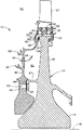
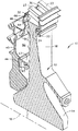
図1及び図2に示すのは、ガスタービンエンジンのロータディスク組立体10内のディスク12についての例示的な実施形態である。ディスク12は、中心線16の周りを囲む環状のハブ14を含む。環状のウェブ18が、ハブ14から半径方向外向きに延び、環状のリム22が、ウェブの半径方向外側端24に配置される。リム22は、ウェブ18を越えて軸方向後方及び前方に延びる。複数のダブテールスロット30が、リム22をほぼ軸方向に貫通して、該リブ間にディスクポスト23を形成する。複数の冷却空気スロット32が、ウェブ18の前方でリム22をほぼ半径方向に貫通し、図3及び図5に示すように、中心線16に対して周方向にスキューされ(斜めにされ)、かつ図4に示すように中心線16に垂直な基準半径NRに対して軸方向後方に傾斜されている。
Illustrated in FIGS. 1 and 2 is an exemplary embodiment for a
図3、図4、及び図5に示すのは、各冷却空気スロット32の1つの例示的な実施形態であり、該冷却空気スロット32は、図示するように、中心線16に対して、冷却空気スロット32の中央線94と中心線16との間のスキュー角度100だけ周方向にスキューされた(斜めにされた)平行な側壁面36を有する。側壁面間で延びる後方壁面38は、図示するように、中心線に垂直である基準半径NRに対して、図4に示すような後方壁面38と基準半径NRとの間の傾斜角度102だけ軸方向後方に傾斜されている。フィレット42が、側壁面36の各々と後方壁面38との間に形成される。各フィレット42は、フィレット曲率半径FRを有する。後方壁面38は、湾曲しかつ壁面曲率半径WRを有する。
Shown in FIGS. 3, 4, and 5 is one exemplary embodiment of each
ここに示す例示的な実施形態では、冷却空気スロット32及び側壁面36は、中心線16に対してスキュー角度100の値である約5度だけ周方向に斜めにされており、また後方壁面38は、中心線16に垂直である基準半径NRに対して、傾斜角度102の値である約18度だけ軸方向後方に傾斜されている。壁面半径WRは、冷却空気スロット32の側壁面36間の幅Wにほぼ等しい。壁面曲率半径WRは、フィレット曲率半径FRより約4倍大きい。
In the exemplary embodiment shown here, the cooling
再び図1及び図2を参照すると、ディスク12は、該ディスクとウェブ18の軸方向前方に配置された環状のフェースプレート40とを含むガスタービンエンジンのロータディスク組立体10に用いるように設計されている。環状のフェースプレート40は、組立体の半径方向に間隔を置いた半径方向内側及び外側位置44及び46においてディスク12と係合しかつ該ディスク12に当接してシールして、前記2つの位置の間でディスクとフェースプレートとの間に環状の流路50を形成する。冷却空気54は、プレート40内の穴56を通って流路50に入り、リム22に向かって半径方向外向きに流れる。バイオネット継手58が、外側位置46においてプレート40をディスク12に固定する。プレート40内のボルト穴63とディスク12の延長部67のフランジ65とにより示されているボルト継手60が、内側位置44においてプレート40をディスク12に固定する。
1 and 2, the
バイオネット継手58は、リム22の周りに周方向に配置されかつ該リムの前方端66から半径方向内向きに延びるリムタブ64(図4も参照)を含む。冷却空気スロット32は、リムタブ64の少なくとも幾つかの間で延びる。プレートタブ68は、外側位置46においてプレート40から半径方向外向きに延びる。組立時に、プレート40は、プレートタブ68をリムタブ64と係合させた状態で旋回させられて、該プレートがディスク12に固定される。半径方向内側及び外側シール歯状突起90及び92は、プレート40の穴56の半径方向内側及び外側の位置から半径方向外向きに延びる。
The bayonet joint 58 includes a rim tab 64 (see also FIG. 4) that is circumferentially disposed about the
冷却空気スロット32は、冷却空気54が環状の流路50からダブテールスロット30に流れるための流体通路を形成し、このダブテールスロット30から冷却空気54が、タービン流路62を横切って配置されたタービンブレード57に供給される。タービンブレード57は、ダブテール根元59によりダブテールスロット30内に取付けられる。冷却空気スロット32は、環状の流路50からダブテールスロット30に向かう冷却空気54の遠心力による半径方向のポンピング作用をもたらす。冷却空気54は、ダブテールスロット30からブレード57内の冷却空気通路61を通って流れ、タービン流路62内に排出される。冷却空気流路61とそれを横切ってブレード57が配置されているタービン流路62との間の圧力差により、環状の流路50からダブテールスロット30への冷却空気54の追加の流れがもたらされる。
The cooling
軸方向にカットバックされかつ周方向にスキューされた冷却空気スロットは、空気スロット中の応力を低下させて、低サイクル疲労を減少させかつディスクの全寿命を改善する。軸方向にカットバックされかつ周方向にスキューされた冷却空気スロットは、応力ピークを空気スロットの後方壁面に移動させることによる製造のばらつきに対する感受性の低下により、一層堅牢な設計を得ることを可能にする。また、ダブテールスロットの底部位置は、空気スロットを計測するのにより容易な位置であり、従って、寸法点検で見逃される可能性がより少ない。 Axial cut back and circumferentially skewed cooling air slots reduce stress in the air slots to reduce low cycle fatigue and improve overall disk life. Axial cutback and circumferentially skewed cooling air slots allow for a more robust design due to reduced susceptibility to manufacturing variations by moving stress peaks to the rear wall of the air slot To do. Also, the bottom position of the dovetail slot is an easier position to measure the air slot and is therefore less likely to be missed during dimensional inspection.
本発明を、例示的な方法で説明してきた。用いてきた用語は、限定するのではなく説明する語句の性質をおびたものとすることを意図していることを理解されたい。本明細書では本発明の好ましくかつ例示的な実施形態であると考えられるものを説明してきたが、本発明の他の変更形態が本明細書の教示から当業者には明らかになるはずである。なお、特許請求の範囲に記載された符号は、理解容易のためであってなんら発明の技術的範囲を実施例に限縮するものではない。 The invention has been described in an illustrative manner. It should be understood that the terminology used is intended to be inclusive of the nature of the phrase being described rather than limiting. While this specification has described what is considered to be the preferred and exemplary embodiments of the present invention, other modifications of the present invention should become apparent to those skilled in the art from the teachings herein. . In addition, the code | symbol described in the claim is for easy understanding, and does not limit the technical scope of an invention to an Example at all.
10 ガスタービンエンジンのロータディスク組立体
12 ロータディスク
14 環状のハブ
16 中心線
18 ウェブ
22 リム
30 ダブテールスロット
32 冷却空気スロット
40 フェースプレート
50 環状の流路
54 冷却空気
56 穴
57 タービンブレード
58 バイオネット継手
60 ボルト継手
61 冷却空気通路
62 タービン流路
64 リムタブ
68 プレートタブ
10 Gas Turbine Engine
Claims (10)
前記ハブ(14)から半径方向外向きに延びる環状のウェブ(18)と、
前記ウェブ(18)の半径方向外側端(24)に配置された環状のリム(22)と、
前記リム(22)をほぼ軸方向に貫通する複数のダブテールスロット(30)と、
前記リム(22)をほぼ半径方向に貫通する複数の冷却空気スロット(32)と、を含み、
前記冷却空気スロット(32)が、前記中心線(16)に対して周方向に斜めにされ、かつ前記中心線(16)に垂直な基準半径(NR)に対して軸方向後方に傾斜されている、
ことを特徴とするガスタービンエンジンのロータディスク(12)。 An annular hub (14) surrounding the centerline (16);
An annular web (18) extending radially outward from the hub (14);
An annular rim (22) disposed at a radially outer end (24) of the web (18);
A plurality of dovetail slots (30) extending substantially axially through the rim (22);
A plurality of cooling air slots (32) extending substantially radially through the rim (22);
The cooling air slot (32) is inclined in the circumferential direction with respect to the center line (16) and is inclined axially rearward with respect to a reference radius (NR) perpendicular to the center line (16). Yes,
A rotor disk (12) for a gas turbine engine, characterized in that
前記後方壁面(38)が、湾曲しかつ壁面曲率半径(WR)を有し、
前記壁面半径(WR)が、前記冷却空気スロット(32)の前記壁面(36)間の幅(W)にほぼ等しい、
ことを特徴とする、請求項2又は請求項3に記載のディスク(12)。 A fillet (42) having a fillet radius of curvature (FR) between each of the side wall surfaces (36) and the rear wall surface (38);
The rear wall surface (38) is curved and has a wall surface radius of curvature (WR);
The wall surface radius (WR) is approximately equal to the width (W) between the wall surfaces (36) of the cooling air slot (32);
Disc (12) according to claim 2 or claim 3, characterized in that.
中心線(16)の周りを囲む環状のハブ(14)を有するディスク(12)と、
前記ハブ(14)から半径方向外向きに延びる環状のウェブ(18)と、
前記ウェブ(18)の半径方向外側端(24)に配置された環状のリム(22)と、
前記リム(22)をほぼ軸方向に貫通する複数のダブテールスロット(30)と、
前記リム(22)をほぼ半径方向に貫通する複数の冷却空気スロット(32)と、を含み、
前記冷却空気スロット(32)が、前記中心線(16)に対して周方向に斜めにされ、かつ前記中心線(16)に垂直な基準半径(NR)に対して軸方向後方に傾斜されており、
環状のフェースプレート(40)が、前記ウェブ(18)の軸方向前方に配置されかつ前記組立体の半径方向に間隔を置いた半径方向内側及び外側位置(44及び46)において前記ディスク(12)と係合して、前記位置の間で前記ディスクと前記プレートとの間に環状の流路(50)を形成している、
ことを特徴とする組立体(10)。 A rotor disk assembly (10) for a gas turbine engine comprising:
A disc (12) having an annular hub (14) surrounding a centerline (16);
An annular web (18) extending radially outward from the hub (14);
An annular rim (22) disposed at a radially outer end (24) of the web (18);
A plurality of dovetail slots (30) extending substantially axially through the rim (22);
A plurality of cooling air slots (32) extending substantially radially through the rim (22);
The cooling air slot (32) is inclined in the circumferential direction with respect to the center line (16) and is inclined axially rearward with respect to a reference radius (NR) perpendicular to the center line (16). And
An annular faceplate (40) is disposed axially forward of the web (18) and radially spaced at the radially inner and outer positions (44 and 46) of the assembly (12). To form an annular flow path (50) between the disk and the plate between the positions,
An assembly (10) characterized in that.
前記冷却空気スロット(32)が、前記リムタブ(64)の少なくとも幾つかの間で延びており、
プレートタブ(68)が、前記外側位置において前記プレート(40)から半径方向外向きに延びている、
ことを特徴とする、請求項8に記載の組立体(10)。 A rim tab (64) disposed circumferentially around the rim and extending radially inward from a forward end (66) of the rim (22);
The cooling air slot (32) extends between at least some of the rim tabs (64);
A plate tab (68) extends radially outward from the plate (40) in the outer position;
9. Assembly (10) according to claim 8 , characterized in that.
Applications Claiming Priority (1)
| Application Number | Priority Date | Filing Date | Title |
|---|---|---|---|
| US10/231,420 US6749400B2 (en) | 2002-08-29 | 2002-08-29 | Gas turbine engine disk rim with axially cutback and circumferentially skewed cooling air slots |
Publications (3)
| Publication Number | Publication Date |
|---|---|
| JP2004092644A JP2004092644A (en) | 2004-03-25 |
| JP2004092644A5 JP2004092644A5 (en) | 2006-10-05 |
| JP4272483B2 true JP4272483B2 (en) | 2009-06-03 |
Family
ID=31495388
Family Applications (1)
| Application Number | Title | Priority Date | Filing Date |
|---|---|---|---|
| JP2003303865A Expired - Fee Related JP4272483B2 (en) | 2002-08-29 | 2003-08-28 | Gas turbine engine disc rim with axially cut back and circumferentially skewed cooling air slots |
Country Status (5)
| Country | Link |
|---|---|
| US (1) | US6749400B2 (en) |
| EP (1) | EP1394358B1 (en) |
| JP (1) | JP4272483B2 (en) |
| CN (1) | CN100359133C (en) |
| DE (1) | DE60318977T2 (en) |
Families Citing this family (32)
| Publication number | Priority date | Publication date | Assignee | Title |
|---|---|---|---|---|
| US7192245B2 (en) * | 2004-12-03 | 2007-03-20 | Pratt & Whitney Canada Corp. | Rotor assembly with cooling air deflectors and method |
| DE102005059084A1 (en) * | 2005-12-10 | 2007-06-14 | Mtu Aero Engines Gmbh | Turbomachine, in particular gas turbine |
| GB2435909A (en) * | 2006-03-07 | 2007-09-12 | Rolls Royce Plc | Turbine blade arrangement |
| FR2918104B1 (en) * | 2007-06-27 | 2009-10-09 | Snecma Sa | DEVICE FOR COOLING THE ALVEOLS OF A TURBOMACHINE ROTOR DISC WITH DOUBLE AIR SUPPLY. |
| FR2928406A1 (en) * | 2008-03-07 | 2009-09-11 | Snecma Sa | Rotor disk for aeronautical turbomachine, has projections provided at downstream end of clamp of disk, where each projection axially cooperates with another projection of flange when clamp of flange is placed around clamp of disk |
| FR2937371B1 (en) * | 2008-10-20 | 2010-12-10 | Snecma | VENTILATION OF A HIGH-PRESSURE TURBINE IN A TURBOMACHINE |
| US8172506B2 (en) * | 2008-11-26 | 2012-05-08 | General Electric Company | Method and system for cooling engine components |
| US8740554B2 (en) | 2011-01-11 | 2014-06-03 | United Technologies Corporation | Cover plate with interstage seal for a gas turbine engine |
| US8662845B2 (en) | 2011-01-11 | 2014-03-04 | United Technologies Corporation | Multi-function heat shield for a gas turbine engine |
| US8840375B2 (en) | 2011-03-21 | 2014-09-23 | United Technologies Corporation | Component lock for a gas turbine engine |
| US9145772B2 (en) | 2012-01-31 | 2015-09-29 | United Technologies Corporation | Compressor disk bleed air scallops |
| US9091173B2 (en) | 2012-05-31 | 2015-07-28 | United Technologies Corporation | Turbine coolant supply system |
| US10119400B2 (en) | 2012-09-28 | 2018-11-06 | United Technologies Corporation | High pressure rotor disk |
| US9228443B2 (en) * | 2012-10-31 | 2016-01-05 | Solar Turbines Incorporated | Turbine rotor assembly |
| US9677407B2 (en) | 2013-01-09 | 2017-06-13 | United Technologies Corporation | Rotor cover plate |
| WO2014120135A1 (en) * | 2013-01-30 | 2014-08-07 | United Technologies Corporation | Double snapped cover plate for rotor disk |
| US10253642B2 (en) | 2013-09-16 | 2019-04-09 | United Technologies Corporation | Gas turbine engine with disk having periphery with protrusions |
| EP3047112B1 (en) | 2013-09-17 | 2018-11-14 | United Technologies Corporation | Gas turbine engine with seal having protrusions |
| EP2860351A1 (en) | 2013-10-10 | 2015-04-15 | Siemens Aktiengesellschaft | Assembly for securing a function position of a side plate on a rotor disk arranged relative to a rotor blade assembled on the rotor disk |
| US10221708B2 (en) * | 2014-12-03 | 2019-03-05 | United Technologies Corporation | Tangential on-board injection vanes |
| US9810087B2 (en) | 2015-06-24 | 2017-11-07 | United Technologies Corporation | Reversible blade rotor seal with protrusions |
| GB201514212D0 (en) * | 2015-08-12 | 2015-09-23 | Rolls Royce Plc | Turbine disc assembly |
| US10612383B2 (en) * | 2016-01-27 | 2020-04-07 | General Electric Company | Compressor aft rotor rim cooling for high OPR (T3) engine |
| FR3064667B1 (en) * | 2017-03-31 | 2020-05-15 | Safran Aircraft Engines | DEVICE FOR COOLING A TURBOMACHINE ROTOR |
| US10280842B2 (en) * | 2017-04-10 | 2019-05-07 | United Technologies Corporation | Nut with air seal |
| US10975714B2 (en) * | 2018-11-22 | 2021-04-13 | Pratt & Whitney Canada Corp. | Rotor assembly with blade sealing tab |
| CN109489957B (en) * | 2018-12-10 | 2020-12-15 | 中国航发四川燃气涡轮研究院 | A switching structure that is used for experimental area stress of rim plate to cut apart groove |
| CN111828108B (en) * | 2020-07-24 | 2023-02-21 | 中国科学院工程热物理研究所 | Cover plate disc structure for engine turbine disc prerotation system |
| CN112459851B (en) * | 2020-10-27 | 2021-12-17 | 中船重工龙江广瀚燃气轮机有限公司 | Turbine movable blade cooling air supercharging device |
| CN112302731B (en) * | 2020-10-27 | 2022-11-18 | 西北工业大学 | Radial rim sealing structure for multi-row tapered cylindrical hole shape of turbine disc |
| RU208145U1 (en) * | 2021-06-07 | 2021-12-06 | Публичное Акционерное Общество "Одк-Сатурн" | High pressure turbine rotor assembly |
| US11795821B1 (en) | 2022-04-08 | 2023-10-24 | Pratt & Whitney Canada Corp. | Rotor having crack mitigator |
Family Cites Families (17)
| Publication number | Priority date | Publication date | Assignee | Title |
|---|---|---|---|---|
| US2951340A (en) * | 1956-01-03 | 1960-09-06 | Curtiss Wright Corp | Gas turbine with control mechanism for turbine cooling air |
| US3748060A (en) * | 1971-09-14 | 1973-07-24 | Westinghouse Electric Corp | Sideplate for turbine blade |
| US4344738A (en) * | 1979-12-17 | 1982-08-17 | United Technologies Corporation | Rotor disk structure |
| JPH0231355U (en) * | 1988-08-19 | 1990-02-27 | ||
| FR2663997B1 (en) * | 1990-06-27 | 1993-12-24 | Snecma | DEVICE FOR FIXING A REVOLUTION CROWN ON A TURBOMACHINE DISC. |
| US5143512A (en) | 1991-02-28 | 1992-09-01 | General Electric Company | Turbine rotor disk with integral blade cooling air slots and pumping vanes |
| JPH0571305A (en) * | 1991-03-04 | 1993-03-23 | General Electric Co <Ge> | Platform assembly installing rotor blade to rotor disk |
| US5275534A (en) | 1991-10-30 | 1994-01-04 | General Electric Company | Turbine disk forward seal assembly |
| US5333993A (en) * | 1993-03-01 | 1994-08-02 | General Electric Company | Stator seal assembly providing improved clearance control |
| JP3052980B2 (en) * | 1993-07-13 | 2000-06-19 | 株式会社日立製作所 | Refrigerant recovery type gas turbine |
| FR2744761B1 (en) * | 1996-02-08 | 1998-03-13 | Snecma | LABYRINTH DISC WITH INCORPORATED STIFFENER FOR TURBOMACHINE ROTOR |
| GB9615394D0 (en) * | 1996-07-23 | 1996-09-04 | Rolls Royce Plc | Gas turbine engine rotor disc with cooling fluid passage |
| US5984636A (en) * | 1997-12-17 | 1999-11-16 | Pratt & Whitney Canada Inc. | Cooling arrangement for turbine rotor |
| US5984630A (en) | 1997-12-24 | 1999-11-16 | General Electric Company | Reduced windage high pressure turbine forward outer seal |
| DE59810560D1 (en) * | 1998-11-30 | 2004-02-12 | Alstom Switzerland Ltd | blade cooling |
| JP2000186502A (en) * | 1998-12-24 | 2000-07-04 | Hitachi Ltd | Gas turbine |
| US6331097B1 (en) | 1999-09-30 | 2001-12-18 | General Electric Company | Method and apparatus for purging turbine wheel cavities |
-
2002
- 2002-08-29 US US10/231,420 patent/US6749400B2/en not_active Expired - Fee Related
-
2003
- 2003-08-28 JP JP2003303865A patent/JP4272483B2/en not_active Expired - Fee Related
- 2003-08-29 EP EP03255403A patent/EP1394358B1/en not_active Expired - Fee Related
- 2003-08-29 DE DE60318977T patent/DE60318977T2/en not_active Expired - Lifetime
- 2003-08-29 CN CNB031557066A patent/CN100359133C/en not_active Expired - Fee Related
Also Published As
| Publication number | Publication date |
|---|---|
| US6749400B2 (en) | 2004-06-15 |
| CN100359133C (en) | 2008-01-02 |
| JP2004092644A (en) | 2004-03-25 |
| CN1490496A (en) | 2004-04-21 |
| EP1394358B1 (en) | 2008-02-06 |
| EP1394358A2 (en) | 2004-03-03 |
| EP1394358A3 (en) | 2005-11-23 |
| DE60318977T2 (en) | 2009-02-05 |
| DE60318977D1 (en) | 2008-03-20 |
| US20040042900A1 (en) | 2004-03-04 |
Similar Documents
| Publication | Publication Date | Title |
|---|---|---|
| JP4272483B2 (en) | Gas turbine engine disc rim with axially cut back and circumferentially skewed cooling air slots | |
| US6375429B1 (en) | Turbomachine blade-to-rotor sealing arrangement | |
| US8016552B2 (en) | Stator—rotor assemblies having surface features for enhanced containment of gas flow, and related processes | |
| JP4785511B2 (en) | Turbine stage | |
| JP5595775B2 (en) | Methods, systems, and / or apparatus for turbine engine seals | |
| JP6514511B2 (en) | High-wing blade with two partial span shrouds and a curved dovetail | |
| US9145788B2 (en) | Retrofittable interstage angled seal | |
| EP1211386A2 (en) | Turbine interstage sealing ring | |
| JP6888907B2 (en) | gas turbine | |
| JP2005248959A (en) | Turbo machinery such as turbo jet for aircraft | |
| JP2007154889A (en) | Turbine nozzle and turbine engine | |
| KR20170077802A (en) | Tip shrouded turbine rotor blades | |
| JP2016211547A (en) | Rotor blade having flared tip | |
| JP6732920B2 (en) | Flexible damper for turbine blades | |
| JP6669484B2 (en) | Channel boundaries and rotor assemblies in gas turbines | |
| JP2016125493A (en) | Flow path boundary and rotor assemblies in gas turbines | |
| US11015452B2 (en) | Gas turbine blade | |
| JP6725241B2 (en) | Flowpath boundary and rotor assembly in a gas turbine | |
| US20170175557A1 (en) | Gas turbine sealing | |
| JPS62195402A (en) | Shroud device controlling nose clearance of turbine rotor blade | |
| JP5507340B2 (en) | Turbomachine compressor wheel member | |
| US20130318982A1 (en) | Turbine cooling apparatus | |
| US10247013B2 (en) | Interior cooling configurations in turbine rotor blades | |
| US10704400B2 (en) | Rotor assembly with rotor disc lip | |
| JP7042559B2 (en) | Nozzle cooling system for gas turbine engines |
Legal Events
| Date | Code | Title | Description |
|---|---|---|---|
| A521 | Written amendment |
Free format text: JAPANESE INTERMEDIATE CODE: A523 Effective date: 20060818 |
|
| A621 | Written request for application examination |
Free format text: JAPANESE INTERMEDIATE CODE: A621 Effective date: 20060818 |
|
| TRDD | Decision of grant or rejection written | ||
| A01 | Written decision to grant a patent or to grant a registration (utility model) |
Free format text: JAPANESE INTERMEDIATE CODE: A01 Effective date: 20090203 |
|
| A01 | Written decision to grant a patent or to grant a registration (utility model) |
Free format text: JAPANESE INTERMEDIATE CODE: A01 |
|
| A61 | First payment of annual fees (during grant procedure) |
Free format text: JAPANESE INTERMEDIATE CODE: A61 Effective date: 20090227 |
|
| FPAY | Renewal fee payment (event date is renewal date of database) |
Free format text: PAYMENT UNTIL: 20120306 Year of fee payment: 3 |
|
| R150 | Certificate of patent or registration of utility model |
Free format text: JAPANESE INTERMEDIATE CODE: R150 |
|
| LAPS | Cancellation because of no payment of annual fees |