JP4271889B2 - Deployment actuation system for intratubal contraception - Google Patents
Deployment actuation system for intratubal contraception Download PDFInfo
- Publication number
- JP4271889B2 JP4271889B2 JP2001517975A JP2001517975A JP4271889B2 JP 4271889 B2 JP4271889 B2 JP 4271889B2 JP 2001517975 A JP2001517975 A JP 2001517975A JP 2001517975 A JP2001517975 A JP 2001517975A JP 4271889 B2 JP4271889 B2 JP 4271889B2
- Authority
- JP
- Japan
- Prior art keywords
- contraceptive device
- sheath
- handle
- core shaft
- contraceptive
- Prior art date
- Legal status (The legal status is an assumption and is not a legal conclusion. Google has not performed a legal analysis and makes no representation as to the accuracy of the status listed.)
- Expired - Fee Related
Links
Images


Classifications
-
- A—HUMAN NECESSITIES
- A61—MEDICAL OR VETERINARY SCIENCE; HYGIENE
- A61F—FILTERS IMPLANTABLE INTO BLOOD VESSELS; PROSTHESES; DEVICES PROVIDING PATENCY TO, OR PREVENTING COLLAPSING OF, TUBULAR STRUCTURES OF THE BODY, e.g. STENTS; ORTHOPAEDIC, NURSING OR CONTRACEPTIVE DEVICES; FOMENTATION; TREATMENT OR PROTECTION OF EYES OR EARS; BANDAGES, DRESSINGS OR ABSORBENT PADS; FIRST-AID KITS
- A61F6/00—Contraceptive devices; Pessaries; Applicators therefor
- A61F6/06—Contraceptive devices; Pessaries; Applicators therefor for use by females
-
- A—HUMAN NECESSITIES
- A61—MEDICAL OR VETERINARY SCIENCE; HYGIENE
- A61B—DIAGNOSIS; SURGERY; IDENTIFICATION
- A61B1/00—Instruments for performing medical examinations of the interior of cavities or tubes of the body by visual or photographical inspection, e.g. endoscopes; Illuminating arrangements therefor
- A61B1/307—Instruments for performing medical examinations of the interior of cavities or tubes of the body by visual or photographical inspection, e.g. endoscopes; Illuminating arrangements therefor for the urinary organs, e.g. urethroscopes, cystoscopes
-
- A—HUMAN NECESSITIES
- A61—MEDICAL OR VETERINARY SCIENCE; HYGIENE
- A61F—FILTERS IMPLANTABLE INTO BLOOD VESSELS; PROSTHESES; DEVICES PROVIDING PATENCY TO, OR PREVENTING COLLAPSING OF, TUBULAR STRUCTURES OF THE BODY, e.g. STENTS; ORTHOPAEDIC, NURSING OR CONTRACEPTIVE DEVICES; FOMENTATION; TREATMENT OR PROTECTION OF EYES OR EARS; BANDAGES, DRESSINGS OR ABSORBENT PADS; FIRST-AID KITS
- A61F6/00—Contraceptive devices; Pessaries; Applicators therefor
- A61F6/06—Contraceptive devices; Pessaries; Applicators therefor for use by females
- A61F6/14—Contraceptive devices; Pessaries; Applicators therefor for use by females intra-uterine type
- A61F6/18—Inserters or removers ; Apparatus for loading an intra-uterine device into an insertion tube
-
- A—HUMAN NECESSITIES
- A61—MEDICAL OR VETERINARY SCIENCE; HYGIENE
- A61F—FILTERS IMPLANTABLE INTO BLOOD VESSELS; PROSTHESES; DEVICES PROVIDING PATENCY TO, OR PREVENTING COLLAPSING OF, TUBULAR STRUCTURES OF THE BODY, e.g. STENTS; ORTHOPAEDIC, NURSING OR CONTRACEPTIVE DEVICES; FOMENTATION; TREATMENT OR PROTECTION OF EYES OR EARS; BANDAGES, DRESSINGS OR ABSORBENT PADS; FIRST-AID KITS
- A61F6/00—Contraceptive devices; Pessaries; Applicators therefor
- A61F6/20—Vas deferens occluders; Fallopian occluders
- A61F6/22—Vas deferens occluders; Fallopian occluders implantable in tubes
- A61F6/225—Vas deferens occluders; Fallopian occluders implantable in tubes transcervical
-
- A—HUMAN NECESSITIES
- A61—MEDICAL OR VETERINARY SCIENCE; HYGIENE
- A61B—DIAGNOSIS; SURGERY; IDENTIFICATION
- A61B17/00—Surgical instruments, devices or methods, e.g. tourniquets
- A61B17/28—Surgical forceps
- A61B17/29—Forceps for use in minimally invasive surgery
- A61B17/2909—Handles
- A61B2017/2912—Handles transmission of forces to actuating rod or piston
- A61B2017/2923—Toothed members, e.g. rack and pinion
-
- A—HUMAN NECESSITIES
- A61—MEDICAL OR VETERINARY SCIENCE; HYGIENE
- A61B—DIAGNOSIS; SURGERY; IDENTIFICATION
- A61B17/00—Surgical instruments, devices or methods, e.g. tourniquets
- A61B17/28—Surgical forceps
- A61B17/29—Forceps for use in minimally invasive surgery
- A61B2017/2926—Details of heads or jaws
- A61B2017/2927—Details of heads or jaws the angular position of the head being adjustable with respect to the shaft
- A61B2017/2929—Details of heads or jaws the angular position of the head being adjustable with respect to the shaft with a head rotatable about the longitudinal axis of the shaft
-
- A—HUMAN NECESSITIES
- A61—MEDICAL OR VETERINARY SCIENCE; HYGIENE
- A61B—DIAGNOSIS; SURGERY; IDENTIFICATION
- A61B17/00—Surgical instruments, devices or methods, e.g. tourniquets
- A61B17/28—Surgical forceps
- A61B17/29—Forceps for use in minimally invasive surgery
- A61B2017/2926—Details of heads or jaws
- A61B2017/2932—Transmission of forces to jaw members
- A61B2017/2943—Toothed members, e.g. rack and pinion
Abstract
Description
【0001】
〔関連出願の説明〕
本願は、1999年8月23日に出願された米国仮特許出願第60/150,238号の優先権主張出願であり、かかる米国特許出願の開示内容全体を本明細書の一部を形成するものとしてここに引用する。本願は、本願と同日に出願された米国特許出願(発明の名称は、“Insertion/Deployment Catheter System for Intrafallopian Contraception ”である。なお、この出願に係る代理人事件番号は、16355-003810である。)と関連しており、かかる同日出願の米国特許出願の開示内容全体も又、本明細書の一部を形成するものとしてここに引用する。
【0002】
〔発明の背景〕
本発明は一般に、医用器具、システム及び方法に関する。本発明は、具体的な実施形態では、一時的又は永久卵管内避妊器具、送達用システム及びこれらの配備のための非外科的方法に関する。
【0003】
精子の通過阻止による方法及びホルモン療法を含む既存の非外科的避妊法の理論的有効性は十分確立されているが、大抵の公知の方法の実際の有効性は、期待外れである。これら期待外れの結果となる1つの理由は、手術を行わないで妊娠を抑制する現在利用できる方法は多くの場合、ユーザが相当に気をつけているかどうかで決まるということにある。一般に、使い方を守らなければ結果として、失敗率が極めて高くなる以上、ユーザが守らなくても総合的有効性を向上させるということは極めて困難であることが判明している。
【0004】
ユーザが使い方を守らないことで生じる影響の少ない長期間避妊の一形態は、子宮内器具(IUD)である。IUDは、高度の信頼性をもっていることが判明しており、他の大抵の市販避妊器具よりも長期間にわたって有効である。残念ながら、IUDは重度の感染性合併症と関連がある。この理由で、米国内におけるIUDの使用は激減している。加うるに、IUDは予期しないで逸出したり、症例のかなり高い割合において過度の痛み又は出血が生じるので取り外されるので妊娠を抑制する方法としてのIUDの需要度は一段と減少している。
【0005】
永久不妊術について一般に利用されている選択肢としては、卵管(ファロピオ管)の結紮法及び精管切除法が挙げられる。これら方法は外科的手技なので世界の多くの人に利用できるわけではない。周知の事実として、受精は精子と卵子が出会う卵管内で生じる。卵管結紮法は、卵管の外科的且つ完全な閉塞によりこれを回避する。
【0006】
本発明と関連して行われる手技では、経子宮頸的に弾性コイルを卵管中へ導入して受胎を阻止することがかねてから提案されている。本発明の譲受人に譲渡された米国特許出願第99/15116号は、経子宮頸的に卵管口に挿入され、卵管内に機械的に定着される器具を開示しており、かかる米国特許出願の開示内容全体を本明細書の一部を形成するものとしてここに引用する。この開示された器具は、外科的手技を必要とすることなく、長期間の避妊及び(又は)永久不妊をもたらす組織の内方成長ネットワークを促進することができ、出血及び痛みの増強並びに子宮内器具と関連した感染の恐れが回避される。
【0007】
最近提案された卵管内避妊器具は、この分野において顕著な技術的進歩をもたらしたが、なお一層の改良が望ましい。一般に、妊娠を抑制するための改良型非外科的器具、システム及び方法を提供することが望ましい。これら改良方法により避妊器具の配備の際の容易性、スピード及び信頼性が向上すれば有利である。さらに、これら改良接近及び配備法を多くのアシスタントが居なくても安全且つ効率的に行うことができ、さらに、高価な医用器機を必要としないで外来患者の診療室の医療従事者によって行うことができれば一段と有利である。これら利点のうち幾つか又は全ては、以下に説明する器具によって得られる。
【0008】
〔発明の概要〕
本発明は一般に、改良型医用器具、システム及び方法を提供する。本発明の技術は、避妊器具を卵管口内に経子宮頸的に配備する際の容易さ、速度及び信頼性を向上させるのに特に有用である。本発明は一般に、医療従事者が片手で操作して作動させるようになった取っ手を備える卵管内避妊システムを提供する。代表的には、取っ手は、取っ手を掴むのに用いた手と同じ手で操作できる少なくとも1つのアクチュエータを有している。多くの実施形態では、医療従事者は、取っ手を操作することにより避妊器具を卵管口内に前進させることができ、シースを避妊器具の周りから引っ込めることができ、避妊器具を小さなプロフィールの形態から大きなプロフィールの形態に拡張させることができると共に(或いは)拡張状態の避妊器具を避妊システムの残りの構成部品から離脱させることができ、これら手技は理想的には全て片手で行われる。有利には、これにより、もう片方の手は自由に子宮鏡を掴んでこれを操作することができ、それにより、医療従事者は、二人の別々の人の操作を協調させて標的部位に接近し、避妊器具を配備するという手法に頼らないで、配備状態を光学的に視認して確認しながら、避妊システムを卵管口に向かって差し向けてその配備を行うことができる。変形例として、種々の画像化方式で配備を行ってもよく、かかる画像化方式としては、超音波方式、透視法又は場合によっては、手応えによる誘導方式が挙げられる。種々の細長い配備用構成部品を共通の近位ハウジングに機械的に結合することにより、構成部品を動かす際の混乱が避けられると共に構成部品が固定位置に維持される。それゆえ、本発明により、多種多様な医療管理方式で卵管内避妊器具の配備が容易になる。
【0009】
第1の特徴によれば、本発明は、小さなプロフィールの形態から大きなプロフィールの形態に拡張可能な避妊器具を有する避妊器具送達用システムを提供する。小さなプロフィールの形態の避妊器具は、卵管口内に挿入できる。第1の細長い本体が、近位端部及び遠位端部を備え、受け具が、遠位端部に隣接して設けられている。受け具は、避妊器具をリリース自在に受け入れる。近位取っ手が、第1の細長い本体の近位端部のところに設けられる。取っ手は、手で掴むのに適した寸法形状になっている。少なくとも1つのアクチュエータが、近位取っ手に取り付けられている。アクチュエータは、手で取っ手を掴んだ状態でこの手でアクチュエータを動かして避妊器具を大きなプロフィールの形態に拡張させ、避妊器具を卵管口内に取り付けることができるようになっている。
【0010】
好ましくは、避妊器具送達用システムは、少なくとも1つのアクチュエータの動作により、シースが避妊器具から近位側へ引っ込められるよう受け具を摺動自在に受け入れるルーメンを備えたシースを更に有している。この構造により、医療従事者は、アクチュエータを動かすのに用いた手と同一の手で取っ手を一定位置に保持することにより避妊器具の位置を維持することができる。これにより、もう片方の手は子宮鏡を自由に支持することができるようになり、これは、この子宮鏡は配備処置又は手順を光学的に行うのに用いられる場合が多い。
【0011】
避妊器具送達用システムは、シースを引っ込めた後に露出状態の避妊器具を拡張させる手段を更に有する場合が多い。拡張手段は、避妊器具に結合される場合が多く、アクチュエータによって動作可能である。拡張及びシース引っ込め機構のうちの少なくとも一部を分離することにより、弾性拡張力がシースに作用しないようにすることができ、かかる拡張力は、シースの運動を妨げる場合があるとともに配備中、避妊器具を正確に定位置に保持するのを困難にする場合がある。種々の拡張手段(例えば、ステント状構造部材を塑性変形させる膨張バルーン及び流体ルーメン等)を用いることができるが、好ましい拡張手段は、シースを引っ込めた後に避妊器具の拡張を行うよう第1の細長い本体に対して動く第2の細長い本体を有する。例示の実施形態では、第1及び第2の細長い本体は、少なくとも1つのアクチュエータが第2の細長い本体を動かすまでトルクを維持することにより避妊器具の弾性螺旋外コイルを拘束する。
【0012】
或る実施形態では、取っ手に対する二重機能式アクチュエータの第1の運動により、第2の細長い本体を第1の細長い本体に対して動かさないで、シースが第1の細長い本体に対して動く。第1の運動後における二重機能式アクチュエータの第2の運動により、第2の細長い本体が第1の細長い本体に対して動く。任意的に、ラッチが、第1の細長い本体に対する第2の細長い本体の運動を解除自在に拘束することができる。第1の細長い本体が避妊器具を解除自在に保持する場合が多いので、これにより、配備手順の少なくとも一部の間、避妊器具を標的場所に維持できる。第1の細長い本体は、避妊器具に螺合することができ、取っ手又は結合解除アクチュエータを回すことにより避妊器具から結合解除できる。
【0013】
別の特徴によれば、本発明は、小さなプロフィールの形態から大きなプロフィールの形態に拡張可能な避妊器具を有する避妊器具送達用システムを提供する。小さなプロフィールの形態の避妊器具は、卵管口内に挿入できる。第1の細長い本体が、近位端部及び遠位端部を備える。受け具が、第1の細長い本体の遠位端部に隣接して設けられる。受け具は、避妊器具をリリース自在に受け入れる。シースが、避妊器具の少なくとも一部を摺動自在に受け入れるルーメンを有する。第2の細長い本体が、避妊器具から近位端部まで近位側へ延びる。取っ手が、第1の細長い本体の近位端部のところに設けられる。取っ手は、少なくとも1つのアクチュエータを有し、少なくとも1つのアクチュエータの第1の運動により、シースが避妊器具から近位側へ引っ込められる。少なくとも1つのアクチュエータの第2の運動により、第2の細長い本体が第1の細長い本体に対して動いて避妊器具が大きなプロフィールの形態に拡張される。
【0014】
さらに別の特徴によれば、本発明は、近位端部及び遠位端部を備えた細長い案内構造部材を有する医用器具を提供する。案内構造部材は、横方向に可撓性があり且つ身体内管腔を遠位側へたどって動くのに適するよう遠位端部に向かって可撓性が増大している。近位取っ手が、案内構造部材の近位端部に隣接して取り付けられる。取っ手は、遠位端部に隣接して案内構造部材を横方向に受け入れるスロットを有する。戻止めが、ルーメン内への遠位部分の導入を容易にするようシースを案内構造部材をスロット内に拘束する。
【0015】
本発明では、方法的特徴として、医療従事者が取っ手を手で掴んで取っ手を動かすことにより避妊器具を卵管口内へ経子宮頸的に挿入する。取っ手は、細長い本体によって避妊器具に結合される。手で取っ手を掴んだ状態でこの手で取っ手に設けられたアクチュエータを動かすことにより挿入状態の避妊器具を拡張させる。拡張状態の避妊器具を細長い本体から離脱させて避妊器具が受胎を抑制するようにする。
【0016】
一般に、医療従事者が子宮鏡で卵管口の画像を視認しながら医療従事者がもう片方の手で子宮鏡を操作して避妊器具を卵管口に向かって差し向ける。これにより、医療従事者は、避妊器具送達用システムのこれら2つの構成部品を同時に操作することができ、二人の込み入った協調作業が回避される。
【0017】
〔特定の実施形態の説明〕
本発明は、妊娠を抑制するのに用いることができ、代表的には、妊娠の長期抑制を行い、多くの場合には永久避妊又は不妊をもたらす避妊器具、システム及び方法を提供する。これら避妊器具の少なくとも一部を卵管口に導入することにより、予期せぬ逸出、骨盤の痛み及び感染性合併症の発生の恐れを著しく減少させることができる。本発明は、一般に卵管閉塞法と呼ばれている一群の避妊法に含まれるが、受精を効果的に妨げるには本発明の器具を卵管中に完全に送り進める必要はなく、実施形態によっては、本発明の器具で卵管ルーメンを完全に閉塞する必要はない。本出願人に譲渡された米国特許出願第99/15116号に記載されているように、卵管ルーメンを完全に閉塞すると共に(或いは)完全閉塞を行わないで受精プロセスを完全に妨げることにより、避妊を行ってもよいが、このようにするかどうかは任意である。なお、かかる米国特許出願の開示内容全体を本明細書の一部を形成するものとしてここに引用する。実施形態によっては、例えば銅のような生物活性材料が器具の有効性を高める場合がある。
【0018】
本明細書で用いる場合、構造部材を子宮から卵管口、子宮卵管結合部及び(又は)卵管中へ(任意的にこれらを越えて)送り進める場合には常に構造部材を「卵管口内」に挿入する。
【0019】
次に、図1を参照すると、子宮Uへの接近は一般に、子宮頸Cを通って行われる。子宮U内から、卵管口Oを介して卵管Fに接近する。
【0020】
卵管Fは一般に、卵管口Oと卵管采FIMとの間に3つの部分を有している。子宮Uに隣接したところから始まって、卵管Fの卵管間質部INTは、子宮筋肉組織で囲まれている。子宮卵管結合部UTJのところで始まって、卵管Fは、子宮筋肉を越え、卵管峡部ISCに沿って腹膜腔内へ、そして卵管膨大部AMPに沿って延びている。
【0021】
一般に、本発明の卵管内避妊器具の理想的な配置場所は、卵管の卵管間質部から卵管峡部ISCに及ぶ。半径方向に拡張可能な取付け機構、例えば外コイルが卵管内避妊器具に設けられる場合、この拡張可能又は定着構造部材は好ましくは、子宮卵管結合部UTJに跨がることになる。子宮卵管結合部UTJは、卵管が腹膜腔と出会う平面として定義できることに注目されたい。また、卵管の最も細い部分は必ずしも卵管峡部ISC内に配置される必要はなく、これは卵管用避妊器具(半径方向に拡張可能な定着構造部材を備える場合が多い)を卵管峡部内にいったん配置した場合には特にそうであることが注目されるべきである。事実、本発明と関連した手技の示すところによれば、卵管の事実上最も細い部分は、子宮卵管結合部UTJのところ又はこれに隣接して位置するのがよい。
【0022】
次に、図1Aを参照すると、本発明の避妊器具を配備し、これを用いる例示の方法2の概要説明が、これら避妊器具で用いられる構造部材の選択を理解する上で有用である。どの配備法でも全ての段階を実施する必要があるというわけではないことは理解されるべきである。それにもかかわらず、例示の配備方法2を検討することは、以下に説明する構造部材を理解する上で有用であろう。
【0023】
解剖学的構造及び標的場所を確認する(段階3)ことにより、術者は、卵管口内の避妊器具の好ましい配置場所を判定することができると共に、もし何らかの特定の環境条件が特定の器具配置手順について存在しているかどうかを判定することもできる。子宮鏡検査法、ソノグラフィー(超音波検査法)、透視法等を含む種々の公知の視覚化モードを用いると解剖学的構造及び標的場所の確認を容易に行うことができる。それ故、例示の避妊器具は2以上の画像化方式又は様式を用いると送達に適合させることができる。
【0024】
例示の避妊器具は又、多種多様な解剖学的構造に対応できることが好ましい。2つの要因により、このような多様性があることが重要である。第1に、異なる患者の卵管の解剖学的構造相互間に広いばらつきを観察することができる。第2の要因として、特定の患者の卵管の特定の解剖学的構造を判定して確認することが極めて困難な場合がある。その結果、好ましい避妊器具は、十分に正確な配置(通常の術者のミスについて許容度をもって)を可能にすると共に卵管の種々の部分の長さ及び直径のばらつきについて防護策を備えるのがよい。
【0025】
図1Aの例示の配備方法2は、器具を標的場所に位置決めする段階4を更に有している。この場合も又、多種多様な手技を用いると、医療従事者が器具を正確な場所に配置し(その手段として、視覚化法を含む)、ハイコントラストのマーカ(例えば、ラジオパックマーカ、エコー源性マーカ等)、物理的停止部又は「バンパー(bumper)」を設け(これは、信号を医療従事者に送るような触感的な仕方で基準組織に係合するようになっている)、配置場所が手応えで分かるようにするなどをしやすいようにするのに用いられる。適当な可撓性、ナビゲーション特性、摩擦減少面、小さな送達プロフィール、コーティング等を備えた適当な器具及び(又は)配備システムを提供することにより装置の位置決め作業を大幅に容易にすることができる。この場合も又、装置の位置決め(段階4)は、好ましくは、解剖学的構造のばらつき、術者のミス、視覚化の際の困難性を補償して正確な配置を促進できるようにする。
【0026】
例示の配備方法2では、符号5によって指示された段階で器具を標的位置に配備すると共に(或いは)拡張させる。任意的に、器具及び(又は)配備システムは、拡張が生じている間に器具の拡張の視覚化及び(又は)確認が可能である。
【0027】
一般に、避妊器具は、段階6において標的場所でその配備システムから離脱される。この場合も又、離脱状態の視覚化及び(又は)確認を行うのが有利であり、これは、視覚的に、超音波を介して、透視法等により行うことができる。多種多様な離脱機構を用いて器具を配備システムから結合解除することができることは理解されるべきである。
【0028】
例示の方法では、ターゲット場所での器具の位置を確認することができる(段階7)。この場合も又、離脱後、多くの場合、配置中に用いられる同一の視覚化方式を用いて器具の少なくとも一部を視覚化することにより確認を行うことができる。光学的視覚化方式に加えて、これを、透視法による配置の確認のためのラジオパックマーカ、超音波による配置の確認のためのソノグラフィーマーカ等を使用することにより可能になる。任意的に、例えば特定のマーカの場所を避妊器具2に沿って設けて器具の近位端部及び(又は)遠位端部の特定の場所を指示してもよい。例示の方法2は、器具を標的場所に定着させて安定化させる段階9を更に有している。この段階の特徴は、器具の安定性をモニタするよう器具の視覚化に適合することにある。器具を標的場所に定着させる段階は、応急方式(例えば、卵管ルーメンのばらつきを調節してこれに適合することができる拡張螺旋コイル、拡張ステント様構造部材、拡張編組体等)及び長期方式(例えば、組織反応、例えば内方成長を刺激し、それにより、器具を卵管内の定位置に固定する繊維組織を生じさせるファイバメッシュ又は格子を含むことによって得ることができる)に基づく定着を含むのがよい。同様に、安定性は好ましくは、代表的には、適当な弾性を持つと共にずれを生じないで生理学的な動きに順応するような形状の器具を設計することにより短期と長期の両方について得られよう。器具は好ましくは、痛みを引き起こすことなく又は患者の生活上のエロージョンに起因してその安定性を失うことなく、十分な定着を可能にするようバランスが取られた装用プロフィールであろう。
【0029】
図1Aの例示の方法2に示された最終段階は、効能の発揮である。これは、受胎を阻止するのに十分、卵管の機能及びアーキテクチャを改変するルーメン/スペース充填設計を導入することにより得ることができる。
【0030】
一般に、本発明の器具は、現在用いられているポリエステル繊維等により卵管中の反応性組織応答を刺激するようになっているものであるのがよい。理想的には、この反応は、局所性の高い良性の組織反応として分類できる。この反応の結果として、避妊器具が卵管ルーメンの組織内へ導入され、器具が周囲の組織構造中へしっかりと埋め込まれるようになる。この反応は代表的には、平滑筋細胞の増殖及びこれと関連した線維症の特徴を有する場合がある。さらに、卵管ルーメンは一般に、一般的に受胎に必要な通常の卵管アーキテクチャが存在していないことを示す。卵管ルーメンは又、受胎を抑制するほど器具及び関連の線維症が存在していることにより妨げられ、閉塞され及び(又は)機能的に閉塞される場合がある。この反応は、良性のものであり、器具の外コイルから半径方向外方に約5〜10mm越えて卵管の外壁の解剖学的状態又は構造の変化がないように見える。同様に、通常の卵管アーキテクチャは、器具を軸方向に越えて(代表的には、器具が多くの場合子宮内に入り込むので、器具の遠位側へ)約5mm見える場合が多く、この場合も又、非常に局所的な反応のきざしがある。
【0031】
次に、図1Bを参照すると例示の避妊システム10は主要部として、避妊器具12、避妊器具を部分的に包囲するシース14、リリースカテーテル16及びコアシャフト18を有している。避妊器具12は一般に、近位端部22(シース14内に設けられる)に隣接した近位部分20及び遠位端部26(シース14の遠位端部を越えて露出する)に隣接した遠位部分24を有している。遠位部分24は一般に、システム10を卵管口内に送り進めている間、遠位ガイドワイヤとして働く。近位部分20は、シース14を引っ込めた後に拡張させて避妊器具を配備位置に固定することができる半径方向に拡張可能な構造部材を有している。
【0032】
シース14は、遠位端部28を有していて、近位ハウジング30まで近位側へ延びる全体として管状の構造部材である。シース14は一般に、長さが約25〜50cm、外径が約0.020〜0.060インチ(1インチ=2.54cm)であり、例示のシースの長さは、約39.5cmであり、その外径は約0.04インチである。シース14の内径は、約0.02インチ〜0.05インチの範囲にあるのがよく、例示のシースの内径は、約0.33インチである。
【0033】
リリースカテーテル16は主要部として、避妊器具12に解除自在に係合する遠位端部34及びアクチュエータ33を介してハウジング30に結合された近位端部を備えた管を有している。
【0034】
例示の実施形態では、コアシャフト18は、避妊器具12の遠位部分24の内部から取っ手30まで近位側へ延びる弾性テーパ付き構造部材から成る。コアシャフト18は、シース14の遠位端部28の近位側で避妊器具12に螺合する。例示の実施形態では、コアシャフト18及びリリースカテーテル16は、巻戻しトルクを避妊器具の拡張可能な構造部材に伝えてこの拡張可能な構造部材を小さなプロフィールの形態に維持する。それ故、リリースカテーテル16に対してコアシャフト18を解除すると、拡張可能構造部材を周囲のシースの運動とは無関係に作動させることができる。
【0035】
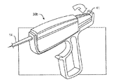
取っ手30は、片手で掴むのに適した寸法形状のハウジング31を有している。指動(親指操作式)ホイールアクチュエータ33が、2つの作動機能を実行する。即ち、まず最初に、ハウジング31に対する指動ホイールの回転により、ピニオン35(指動ホイールに取り付けられている)とラック37(シース14に取り付けられている)が互いに係合してシース14が近位側に引っ張られる。この初期運動中、リリースカテーテル16は、ラッチ39によってハウジング31に対して拘束される。ラック37の近位端部がリリースカテーテル16に取り付けられた協働表面にいったん係合すると、ラッチ39は、指動ホイール33が再び図示の方向に回されるので、リリースカテーテル16がハウジングに対して動くことができるよう作動できる。或る実施形態では、ラッチ39の作動に先立って、指動ホイールの回転によりばね51を圧縮させ、従って、ラッチの作動によりリリースカテーテルが摺動してリリースカテーテルが避妊器具12から離脱するようにしてもよい。この実施形態では、コアシャフト18の近位端部は、コアシャフトがハウジング全体の回転により回転するようにハウジングに取り付けられている。
【0036】
ハウジング31の構成部品及びアクチュエータ33,39は一般に、ポリマー、金属等から成る。アクチュエータ機構は、成形部品及び(又は)機械加工部品を有するのがよく、かかるアクチュエータ機構を、シース14、リリースカテーテル16、コアシャフト18等に永続的に取り付けて避妊器具12をいったん配備すると、送達用システム10の残りの構成部品を処分できるようにするのがよい。変形例として、所望ならば殺菌可能、再使用可能及び(又は)応答性の送達用システム構成部品を用いることが可能である。
【0037】
例示の実施形態では、ハウジング31は、全長が約2〜8インチであり、理想的には長さが約7.5インチである。ラック37の例示の実施形態では、その長さは約5.5cm、総移動行程は約4.0cmである。リリースカテーテル16は、行程が約1cmであり、コアシャフト18に対するリリースカテーテルの運動は、ラッチ39の作動前は阻止される。コアシャフト18は、代表的には約10回転未満で器具12から完全に抜け、理想的には、取っ手(又は他の回転機構)を約1/4〜2回転すると抜ける。
【0038】
例示の避妊器具12は、組織の内方成長中、拡張可能構造部材を拘束するのを助けるために半径方向に拡張可能な螺旋コイルを利用しているが、多種多様な機械的及び他の拘束機構を用いてもよい。例えば、避妊器具に、変形例としての機械的アンカー(又は定着部)、例えば曲がり部、ループ及び(又は)断面が大きくなった他の二次形状物を形成するよう付勢される弾性コイル、スロット付き管、マルコー(Malecot )タイプの構造部材、半径方向に拡張可能なブレード(braid :編組)、ステント様器具等を取り付けてもよい。機械的構造部材は、弾性であって、塑性変形可能等であるのがよく、適当な構造部材は、詳しくは例えばPCT出願公開明細書WO99/15116に記載されている。
【0039】
さらに別の器具拘束技術を採用してもよく、かかる技術としては、熱的手段、化学的手段、接着剤等が挙げられる。これら技術を用いると、器具と周囲の組織との間の摩擦を増大させること、瘢痕組織の形成を促進する組織損傷を抑制すること及び(又は)器具内への組織内方成長を促進することにより逸出を回避することができる。熱的技術としては例えば、避妊システム10に沿う電気的又はレーザエネルギの伝送が挙げられる。避妊器具10の抵抗加熱は、シース14及びリリースカテーテル16に沿って延びる導体を用いて器具の両端に電位差を印加し、又はレーザエネルギをコアワイヤ18に取り付けられた光学導波路に沿って加えること等によって行ってもよい。コアワイヤ18に高周波エネルギを与えることにより大きな戻り電極パッチを介して単極組織乾燥を行ってもよく、或いは、送達用システムのルーメンのうち何れかのもの、専用ルーメン又は構造部材等を用いて接着剤及び(又は)苛性剤(例えば、シアノアクリレート又は硝酸銀)を導入してもよい。また、生分解性栓等を使用でき、保持状態の構造部材は、受胎を抑制する銅又は他の生物活性剤を有するのがよいが、このようにするかどうかは任意である。
【0040】
保持状態の避妊器具12に対する組織反応は、長期の避妊及び(又は)不妊を助けることができる。受胎を抑制する組織反応を促進するため、器具12は、組織反応材料を有する場合が多く、かかる材料は、繊維から成ることが多い。繊維は、ポリエステル、例えば、ダクロン(Dacron:登録商標)ポリエステル、絹、ナイロン等から成るのがよい。繊維は、ウィーブ(weave )、ニット、ブレード、フェルト等の形態をしているのがよく、或いは、器具本体に取り付けられたスタンドから成っていてもよい。
【0041】
図2〜図5を参照すると避妊システム10の構成部品を一層深く理解することができ、図2〜図5には、これら構成部品が個々に示されている。まず最初に図2を参照すると、コアシャフト18は、遠位端部40の近位側へ漸増直径でテーパしていて、遠位部分24、近位部分20及び避妊器具12の近位側のカテーテル構造部材についての漸増直径支持方式を構成している。この漸増直径支持方式(及びこれと関連して支柱強度の増大)により、標的配備部位への接近を行いながら避妊システムを一層容易に押すことができるようになる。ねじ山42は、避妊器具のコイルに螺合し、一般に、互いに分離した巻き部を備えるコイルを接合部44のところで中央コアワイヤに取り付けることにより形成される。管43も又、接合部44のところに取り付けて互いに協働するねじ山が動かなくなったりすると共に(或いは)飛び越えるのを防止するようにするのがよく、管は理想的には、ステンレス鋼、プラチナ等から成る。例示の器具では、コアシャフト18は、高強度金属構造部材から成る。
【0042】
例示の避妊器具12が、図3により詳細に示されている。避妊器具12は、遠位ボールチップ又は球状先端部52から近位ねじ山54まで延びるプライマリコイル50を有し、この遠位球状先端部を有利には、プライマリコイルの近位巻き部を分離することによって形成するのがよい。この実施形態では、螺旋状外コイル56の形態をした拡張可能な構造部材は、巻戻しアタッチメント58を形成するよう折り曲げられた近位端部を有すると共にコイル接合部60のところでコイル50に取り付けられた遠位端部を有している。繊維62が、内コイルと外コイルとの間に延びていて、これ又、避妊器具12の断面全体にわたり組織の内方成長を促進するようプライマリコイル50内に配置されている。コイルアタッチメント58の配置状態と繊維62の位置は、図3Aの軸方向図で見ることができる。ガイドワイヤとして作用できる遠位部分24を備えた避妊器具を利用することにより、避妊器具の中心を通って開口ルーメンを(例えば、別のガイドワイヤのために)設けることは不要となり、多数の接近/配備段階(例えば、ガイドワイヤを用いて標的場所に接近し、カテーテルをガイドワイヤ上でこれに沿って前進させ、ガイドワイヤを位置決めが行われたカテーテルから引き抜き、そして避妊器具を送り進める操作)を回避できる。例示のシステムは、コアワイヤ(又は、他の配備シャフト)と避妊器具を結合するためにねじ山を用いているが、変形例として種々の着脱自在な連結部を用いてもよく、かかる連結部としては、協働するキーとスロット構造等が挙げられる。
【0043】
例示の実施形態では、コイル50は、高強度弾性材料で作られ、理想的には、直径が、0.005インチのステンレス鋼性ワイヤから成っていて、これを巻いて外径が約0.022インチのコイルにしたものである。球状先端部52は好ましくは、コイル50の断面よりも大きな断面を有し、球状先端部は一般に、直径が約0.020インチ〜約0.050インチであり、例示の球状先端部の直径は、0.027インチである。
【0044】
螺旋コイル56は、図1に示すロープロフィール又は小さなプロフィールの形態から標的部位内にリリースされたときの図3に示すこれよりも大きなプロフィールの形態に拡張するよう付勢される高弾性高強度の金属から成る。例示の実施形態では、外コイル56は、超弾性又は形状記憶合金のリボンから成り、厚さは、約0.001インチ、幅は約0.015インチであり、リボンは、拘束されていなければ外径は約0.080インチ、長さは約3.5cmの螺旋コイルを形成するよう付勢される。外コイル56は好ましくは、はんだ接合部60によってプライマリコイル50に固定される。接合部60は好ましくは、球状先端部52から、約0.3cm〜1.0cmの距離だけ離されることになる。有利には、接合部60は、配備前に、避妊器具12の遠位部分24とシース付き近位部分20との間で直径を無外傷性的に増大させるのに役立つようシース14の遠位端部28と整列するのがよい。
【0045】
繊維62は、ポリエステル等から成るのがよい。繊維は、ルーズに製織され、又は絡み合わされたストランドであるのがよく、これら繊維の少なくとも一端は、プライマリコイル50又は外コイル56に取り付けられる。
【0046】
一般的に、拡張可能な構造部材は、少なくとも組織の内方成長が避妊器具を永久的に保持するのに十分生じるようになるまで避妊器具12を定位置に保持するのに役立つ。それ故、拡張可能構造部材は、摩擦の比較的高い外面から利点を得ることが多いであろう。かかる外面は、器具をシース14を施さないで前進させた場合、避妊器具を定位置まで前進させることが困難になる恐れがある。
【0047】
本発明と関連した操作を行って判明したことは、避妊器具を卵管口内に高信頼度で保持するのに十分な強度を有する弾性的に拡張可能な構造部材は、相当大きな摩擦力を周囲のシースに及ぼす場合があるということであった。これら摩擦力は避妊器具の正確な送達を著しく複雑にする場合がある。それ故、外コイル56は好ましくは、巻戻しトルクをコアワイヤ18とリリースカテーテル18との間に及ぼすことにより、シース14内に小さなプロフィールの形態で維持される。コアワイヤは、互いに協働するねじ山42,54を介して巻戻しトルクを外コイル56に伝達することができ、巻戻しトルクの方向は好ましくは、巻戻しトルクがねじ山の結合解除を妨げるように定められる。換言すると、コアワイヤ18を巻戻しトルクと逆の方向に避妊器具12に対して回転させると、コアワイヤ18は避妊器具12から離脱する。
【0048】
巻戻しアタッチメントについての僅かに変形した例が、図3Bに示されている。変形例としての避妊器具12aは、外コイル56の小径の近位部分内にはんだ付けされた小径の管又はバンド59を有している。バンド59は、接合を容易にするためにコイル56内に比較的大きな境界領域を有するのがよい。バンドの使用は、応力集中を回避するのに役立ち、また、リリースカテーテルの結合を抑制する滑らかな内側ルーメンを提供する。バンド59は、ステンレス鋼又はプラチナで作られたものであるのがよく、理想的にはその内径は、約0.023インチ、外径(周囲の外コイルとはんだ接合部の厚さを含む)は、約0.030インチである。これと同様なバンド59′が、ラジオパックマーカとなるようにすると共にねじ山の飛越しを阻止するためにコイル50のねじ山54内に設けられるのがよい。バンド59′は、バンド59と構造が類似しているのがよいが、長さが短い。さらに別の変形例としてのアタッチメント機構を使用できる。例えば、外コイル56の近位端部のところに、はんだ又はコイル材料でできた単純な球、曲がり部等から塊状部又はノブを形成するのがよく、これは、送達用カテーテルのスロットに収納自在に受入れ可能である。
【0049】
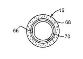
リリースカテーテル16の遠位側の構造が、図4及び図4Aに示されている。巻戻しトルクは、曲がり部58とリリースカテーテル16の遠位端部34のところに設けられたピン66との協働により、外コイル56とリリースカテーテル16との間で解除自在に伝えられる。リリースカテーテル16は主要部として、ポリイミドで作られた管状本体68を有している。ピン66は、管状本体68内のルーメン内に配置され、螺旋支持コイル70及び接着剤72によって管状本体内に支持されている。興味深いことに、種々の寸法形状の管状本体を、リリースカテーテル16によって近位側へ伝えられた巻戻しトルクによって駆動することができる。
【0050】
シース14の構造が、図5により詳細に示されている。シース14の遠位端部28(図5A参照)は好ましくは丸く、この遠位端部は理想的には、避妊器具12のコイル接合部60と協働して摩擦を回避すると共に子宮卵管結合部を通り卵管中に至る送達用システム16の遠位側へのナビゲーションを容易にするようになっている。丸い遠位端部28を任意的にシース14の内周部と外周部の両方に沿って丸くしてもよく、或いは、内方且つ遠位側にテーパするよう主として外周部に沿って丸くしてもよい。
【0051】
シース14は好ましくは、トラッキング(たどって動くこと)及びナビゲーション中の摩擦を減少させる親水性の被膜76を有する(外側から始まる)多層構造を有する。かかる親水性被膜は、流体にさらされると極めて滑りやすくなる。親水性被膜76の下には、シース14の近位部分に沿って、ポリマー、例えばテコフレックス(Tecoflex:登録商標)の構造的な層78が設けられており、金属、理想的にはステンレス鋼の補強ブレード80が、ポリマー層78の下でポリイミドの層内に設けられている。金属製のブレード80が、シース14のより遠位側の部分に沿って、テコフレックス等のポリマー層78内に設けられるが、可撓性を高めるためにポリイミド層は設けられていない。シース14の内側ルーメンは、低摩擦のポリマー被膜84によって構成され、低摩擦ポリマーは理想的には、PTFE、例えばテフロン(Teflon:登録商標)から成る。例示のシース14は、種々の製造業者から市販されたものであるのがよい。適当な構造は、PCT出願公開明細書WO98/57589により詳細に説明されており、かかるPCT出願公開明細書の開示内容全体を本明細書の一部を形成するものとしてここに引用する。
【0052】
図5A〜図5Fに概略的に示すように、変形例としてとしてのシース14a,14b,14cは、それぞれバンパー57,57′,57″を有している。バンパー57は、その下に位置するシースの外面から半径方向に延びる外面を有している。バンパー57は、シース14aが標的配備位置を越えて遠位側に前進していることが手応え又は触覚で分かるようにすることができるが(このようにするかどうかは任意である)、バンパーが卵管口に入ることができるようにシースが前進するのを必ずしも阻止する必要はない。バンパー57は、バンパーが卵管口の先へ進むようにシースを押すのを防ぐ目に見えるマーカを更に備えるのがよい。バンパー57は、着色接着剤を有するのがよく、或いは、着色された材料のバンド又は帯が下に設けられた透明な接着剤を有していてもよいが、このようにするかどうかは任意である。
【0053】
変形例としてのバンパー57′,57″は、理想的には、ポリエチレン又は超弾性形状記憶合金から成るポリマー又は金属構造部材で構成されたものである。これら半径方向に拡張可能なバンパー構造部材は、子宮鏡の作業ルーメンを通って送達できるように押潰し可能であり、次に、卵管口に隣接した子宮組織に係合することによりシースの前進を阻止するよう拡張可能である。
【0054】
次に、図6を参照すると、リリースカテーテル16のピン66と外コイル56の曲がり部58との間の摺動係合状態が、一層明確に示されている。図6は又、コアシャフト18及びリリースカテーテル16によって外コイルに加えられた巻戻しトルクがどのようにして外コイルをシース14内で小さなプロフィールの形態に維持するのを助け、シースを容易に引っ込め又は引き抜くことができるかを示している。リリースカテーテル16を摺動させてピン66が摺動して曲がり部58から外れるようにすることにより巻戻しトルクを解除することができる。任意的に、まず最初にリリースカテーテルがコアシャフトに対して回転して曲がり部58とピン66との間の係合力を減少させるようにしてもよい。
【0055】
次に、図7を参照すると、指動ホイール33及びラッチ39は、有利には、外科医、看護婦又は他の医療従事者の親指で作動可能に位置決めされ、その間、この医療従事者は手の残りの指で取っ手30を握る。これにより、医療従事者は片手で配備段階のうち幾つかを行うことができる。一般に、ハウジング31全体の運動は、避妊器具12を遠位側へ卵管口内へ送り進め、避妊器具を送達用システムを子宮卵管結合部及び卵管内でナビゲートするのに用いられる。避妊器具をいったん位置決めすると、指動ホイール33を用いてシース14を避妊器具上から引っ込め、その間、ハウジング31はリリースカテーテル16及びコアシャフト18の近位端部を引き続き回転可能且つ軸方向に結合し、それにより、避妊器具に加わる巻戻しトルクを維持して避妊器具をその直径の小さな形態に拘束する。
【0056】
避妊器具の近位部分をいったん露出させると、ラッチ39を押して指動ホイール33を再び近位側に回転させ、リリースカテーテル16のピン66を避妊器具の巻戻し外コイルから外し、それにより避妊器具を半径方向に拡張させることができる。有利には、拡張に先立って、避妊器具をシース14内へ引き戻すと共に(或いは)避妊器具を所望ならば卵管口内に僅かに再位置決めすることができる。
【0057】
避妊器具をいったん露出させると共に拡張させると、取っ手30を図示のように回転させてコアシャフト18を避妊器具12から離脱させる。それ故、ハンドル30により、医療従事者は、避妊器具を位置決めし、避妊器具を露出させ、避妊器具を作動させてこの器具を周囲の組織に取り付けるようにし、そして、片手で避妊器具を送達用システムの残りの構成部品から結合解除できるようにする。
【0058】
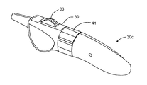
図8A〜図11を参照すると理解できるように、多種多様な変形例としての片手用のリリース取っ手が、図1Bの避妊器具送達用システムと共に用いられる。次に、図8A及び図8Bを参照すると、軸方向動作式“T”取っ手30aが注射器の動きのような軸方向の引張運動を用いてシース30を手の指で手のひら(これは一般に、固定位置に保持される)に向かって引き戻す。これにより、シース14の軸方向運動が生じてシースが避妊器具上から引っ込められ、次に、避妊器具を拡張させることができるリリースカテーテル16の軸方向運動が生じる。任意的に、ノブ41をコアシャフト18の近位端部に取り付けてノブ41の回転により、コアワイヤと拡張状態の避妊器具の螺合関係を解くことができるようにしてもよい。ノブ41は、ノブをハウジングに結合してコアシャフトの回転を阻止すると共にリリースが望まれるまで巻戻しトルクを維持する解除自在なラッチを有するのがよい。有利には、軸方向動作式取っ手30aを用いることにより、使用する手の大きさ及び位置は様々であってよく、しかも、医者にお馴染みの形態が得られる。
【0059】
図9A及び図9Bは、避妊器具を片手で配備できるようにする更に別の変形例としての拳銃の握りの形をした取っ手30bを示している。この実施形態では、トリガアクチュエータ33が、シース14を移動させてビードチェーン45及びビードチェーン駆動ホイール及び歯車装置を介してカテーテル16をリリースする。トリガアクチュエータ43を例えば手の人差し指で作動させた後、ラッチボタン(図示せず)を押し下げ、ノブ41を手の親指で回転させて避妊器具をコアシャフト18から結合解除することができる。
【0060】
次に、図10を参照すると、好ましい片手用リリース取っ手30cは、周囲のハウジングに対して回されると、以下に説明するように最初にコアシャフト18に対するシース14の運動を引き起こす指動ホイール33を有している。避妊器具をいったん露出させると、安全ラッチ39を押し下げることにより、指動ホイールを再び回転させてリリースカテーテル16をコアシャフトに対して動かし、避妊器具を拡張させることができる。指動ホイール33のこのような運動は、好ましい取っ手30cのハウジングを固定位置に維持した状態で容易に行うことができ、それにより、避妊器具の動きが回避される。配備により、避妊器具が標的場所でいったん露出されて拡張されると、この場合も又、残りの取っ手を固定場所に保持した状態でノブ41を回すことができる。このような動きをもたらす内部機構が、図11D、図11E、図11F及び図11Hに示されている。
【0061】
さらに別の変形例としての片手用リリース取っ手が提供され、かかる取っ手としては、図10に示すようにコアシャフト18に対するシース14の運動及びその次に行われるリリースカテーテル16の運動を行うための指動スライダ47を備えたインラインスライダ取っ手30dが挙げられる。ラッチ39を押し下げることにより、ノブ41がハウジングに対して回転できるようにし、或いは、ハウジング全体を回転させて上述のように噛み合いねじ山を互いに離脱させることができる。
【0062】
図11A〜図11Kを参照すると、避妊システム10を用いる例示の方法を理解することができる。好ましくは、医療従事者が、一方の片手H1で避妊器具送達用システム10を操作し、その間、もう一方の片手H2で画像化及び(又は)接近器具、例えば、透視法用カテーテル、超音波検査用カテーテル又は子宮鏡Sを把持する。これにより、医療従事者は、子宮鏡S(目Eで概略的に示されている)を通して処置又は手技を見ながら、避妊システムの遠位側前進運動の配向状態並びにその運動状態及び配備状態を自分で制御することができる。子宮鏡Sは簡単な光学装置として図示されているが、本発明のシステム及び方法では種々の子宮鏡構造を利用でき、かかる構造としては、剛性光学式子宮鏡、束状のコヒーレント光ファイバ付き子宮鏡、処置の画像をモニタ内に表示する電荷結合素子(CCD)を含む子宮鏡等が挙げられる。本発明に用いられる例示の子宮鏡は、イリノイ州シカゴ所在のリチャード・ヴォルフ(Richard Wolf)から5MM Oval Scopeというモデル名で市販されている。
【0063】
次に、図11Bを参照すると、システム10が、一般に光学的誘導下で経子宮頸的に子宮U中に導入されている。外科医は、子宮鏡Sを用いてシステムの遠位端部を卵管Fの口Oへ差し向ける。子宮Uを子宮鏡S及び(又は)別個の灌注又はガス通気システムを用いて灌注すると共に(或いは)拡張するのがよい。卵管口Oの場所をいったん突き止めて子宮鏡Sを卵管口に差し向けると、ガイドワイヤとしての避妊器具の遠位部分24によりシステム10を子宮鏡の作業ルーメンを通って遠位側へ、そして卵管口を通り、そして卵管内へ前進させるが、その間、避妊器具の残部は、シース14によって覆われたままである。
【0064】
シース14の外側親水性被膜は、システム10の前進中、摩擦を最小限に抑え、シースは又、システムに構造的な支柱強度をもたらす。遠位部分24の遠位球状先端部は、卵管F中のトラッキング及びナビゲーションを助け、プライマリコイル構造部材は、横に撓んで卵管内に見受けられることが多い曲がりくねった曲がり部をたどって動く。例示の実施形態では、コアワイヤ18は、遠位部分24内へ延びてシース14を越える遠位部分の支柱強度を高めるが、球状先端部までは延びない。それ故、遠位部分24の剛性は、近位側へ増大し、遠位部分がルーメンをたどって一層動きやすくする。
【0065】
例示の実施形態では、シース14は、子宮鏡Sの視野で見ることができる目視マーカ98を有している。マーカ98は好ましくは、部分的に卵管口O内に位置決めされると共に子宮U内に位置決めされ、それにより避妊器具12が標的位置に配置されていることが分かるようになる(というのは、シース、コアシャフト及び避妊器具が前進及び位置決め中に解除自在に互いにロックされるからである)。上述のようにマーカ98は、バンパー、即ち、手応えにより位置決め状態が分かるようにするためにシースから半径方向に延びる構造部材から成るのがよい。
【0066】
避妊器具12の好ましい位置決め方法が、図11Cに示されている。好ましくは、器具12は、子宮卵管結合部UTJを横切って延び、器具は理想的には、子宮卵管結合部の近位側と遠位側の両方に延びている。卵管間質部INT(図1参照)は、代表的には、長さが約1〜約2cmであり、外コイル56は好ましくは、約0.2〜約1.2cmの距離だけ卵管口Oを越えて子宮U内へ近位側に延びている。外コイル56は好ましくは、少なくとも約0.6cmの距離だけ卵管間質部INT及び(又は)子宮卵管結合部UTJの遠位側に延びている。子宮卵管結合部UTJが卵管Fの一層遠位側の部分のデリケートな卵管組織よりも強度が一層高い場合の多い筋肉組織に隣接して位置しているので、卵管の最も細い部分は(特に、器具12の配備後)、子宮卵管結合部に隣接して見られることが多い。拡張可能構造部材をこの細い部分の遠位側と近位側の両方に延ばすことにより、器具の近位側及び遠位側への運動を止める定着が行われ、それにより、組織内方成長が行われている間、標的位置からの避妊器具12の動きが回避される。有利には、約1cmの範囲の位置決め精度を、マーカ98を1cmの長さに制限することによって得ることができる。これにより、信頼性が高く十分に定着された配備状態が得られるようにしながら、使用しやすさのための十分な位置決め上の許容誤差が得られる。
【0067】
次に、図11C、図11D及び図1Bを参照すると、まず最初にシース14を拡張可能構造部材上から引っ込めることにより、位置決め状態の避妊器具12が配備されている。図10の実施形態を用いて、指動ホイール33を親指THによって近位側に回転させてシース14を避妊器具上から近位側に引き寄せる。指動ホイールを回しながら取っ手30を固定位置に保持し、コアシャフト18が避妊器具12を卵管口内の標的場所に維持するようにする。ラック37がリリースカテーテル16の対応関係にある近位構造部材にいったん係合すると、図11Bを参照すると理解できるように、ラッチ39が押し下げられるまでシース14及び指動ホイール33のそれ以上の運動が阻止される。この時点で、器具12を標的場所に位置決めし、シース14を近位側に引っ込め、避妊器具の近位部分をスコープから見て初期位置決め状態を確認できるようにする。
【0068】
次に、図11F、図11G及び図11Hを参照すると、ラッチ39を押し下げてリリースカテーテル16の近位構造部材をラック37によって軸方向に動かすことができるようにする。ラッチ39の押下げ後、指動ホイール33を再び回転させてシース14とリリースカテーテル16の両方をコアシャフト18に対して近位側に引っ張るのがよい。図11Hで分かり、図6を参照して上述したように、これにより、避妊器具の外コイルがリリースカテーテル16から回転的に結合解除され、リリースカテーテルが拡張できるようにする。
【0069】
図11F及び図11Gに示すダブルアクション式指動ホイール及び安全ラッチ機構が好ましいが、種々の別の露出/拡張機構を採用できる。例えば、再び図1Bを参照すると、ばね51は、ラッチ39が押し下げられるまで、指動ホイール33の回転を阻止する。任意的な手段として、ばね51はラッチ39を作動させると、リリースカテーテル16をコアシャフト18に対して移動させるのに十分なエネルギを保存することができ、或いは、ラッチ39を利用することにより、シース14とリリースカテーテル16の両方をコアシャフト18に対して動かして指動ホイールが拡張可能構造部材を拡張させることができるようばね51を完全に無くしてもよい。
【0070】
コアシャフト14を拡張可能構造部材上からいったん引っ込めてリリースカテーテル16を露出状態の拡張可能構造部材から外し、避妊器具を弾性的に拡張させこれを定位置にいったん取り付けると、ハンドル30を回して避妊器具12を送達用システム10の残りの構成部品から離脱させるのがよい。再び図11F及び図11Gを参照すると、リリースカテーテル16の近位端部に取り付けられた近位構造部材16aを近位側に摺動させると、コアシャフト18の近位構造部材18aを回転させることができる。より詳細には、リリースカテーテルの近位構造部材に設けられたスプラインをコアシャフトの近位構造部材に設けられたこれと協働するスプラインを越えて軸方向に移動させる。コアシャフトの近位構造部材18aは、ノブ41に回転的に結合されていて、互いに協働するスプラインがリリースカテーテルの配備行程前に、ノブの回転を阻止するが、その後、ノブを回転させるとコアシャフト18を避妊器具から結合解除しやすくすることができる。
【0071】
次に、図11I、図11J及び図11Kを参照すると、リリースカテーテル及びコアシャフトの近位構造部材16a,18aがいったん動いてノブ41が自由に回転できるようになると、オペレータは親指TH及び(又は)リリース取っ手30cを保持している手の指でノブを回転させる。上述のように、離脱のためのコアシャフトの回転方向は、巻戻しトルクの回転方向とは逆であり、したがって、巻戻しトルクがねじ山の噛み合い状態の維持を助けるようになる。コアシャフト18を避妊器具12からいったん抜き取ると、コアシャフト及び他の送達用構成部品を子宮鏡S内に近位側へ引っ込めることができる。子宮鏡Sは、子宮U内に位置したままであるのがよく、避妊器具を反対側の卵管口内に配備できるよう別の送達用システムを子宮鏡内へ挿入するのがよい。避妊器具を2つの卵管の両方内に配備すると共に子宮鏡を用いて双方の配備が成功していることを目で見て確かめた後、子宮鏡を図11Kに示すように子宮から経子宮頸的に引っ込める。
【0072】
次に、図12A及び図12Bを参照すると、スロット付き取っ手30dは好ましくは、送達用システム10の遠位部分を図示のように曲げるとシース14を横方向に受け入れるスロット100を有している。図12Bに示す送達用システムの遠位軸線に沿って図を見ると最も明らかに分かるように、スロット100は、送達用システムの遠位端部に隣接してシース14をぴったりと受け入れる。戻止め102が、ハウジングからスロット100内に延び、シース、リリースカテーテル16及びコアシャフト18からの真っ直ぐにする作用をもつ弾性力に抗してシース14をスロット100内に拘束する。
【0073】
取っ手30dから遠位部分24の遠位端部まで遠位側に延びる送達用システム10の細長い構成部品は、遠位端部に向かって遠位側に増大する横方向可撓性を備えた細長い案内構造部材を構成する。この自動案内構造部材をスロット100内に解除自在に固定することにより、案内構造部材を取っ手30dを用いる子宮鏡Sの作業ルーメンW内に容易に挿入することができる。これにより、細長い可撓性ガイドワイヤ状構造部材が、片持ち状態で取っ手から相当長い距離、延びるのが回避され、或いは、送達用システムをシース14の遠位端部に隣接して把持して遠位部分24を作業ルーメン内に挿入した状態で、取っ手の死重が制御不能な状態でばたばたと動くのが回避される。かかる構造部材は、これらの遠位端部を血管接近用カテーテル、挿入用シース、モノレールカテーテルルーメン等内へ挿入しやすくするための近位取っ手を備えたガイドワイヤ及びガイドワイヤ状構造部材について多種多様な用途を持っている。
【0074】
次に、図13を参照すると、変形例としての種々の配備方法が、避妊システム10を配備するのに用いられる。例えば、簡単な子宮頸部用カテーテル102を用いて、配備を超音波検査法、透視法、磁気共鳴画像法及び場合によっては手応えで得られる情報だけで行う。図13に示す変形例としての例示の方法では、子宮頸用カテーテル102のバルーン104を膨らましポート106を介して膨らませる。これにより、子宮頸用カテーテル102の作業ルーメンに挿入された子宮用カテーテル108を介して拡張媒体を導入することにより、子宮Uを拡張することができる。好ましくは、超音波及び(又は)透視画像化法の誘導下で解剖学的構造及び標的場所の識別、器具位置決め、配備、離脱及び位置確認を行う(これらについては、図1Aを参照して方法2において概要説明している)。適切な子宮用カテーテルの操作構造及び方法が、米国特許第5,346,498号及び第5,389,100号に記載されており、これら米国特許の開示内容全体を本明細書の一部を形成するものとしてここに引用する。
【0075】
上述のように、本発明の送達用システムは、避妊器具を露出させ、拡張させると共に(或いは)リリースしている間、避妊器具を固定位置に保持することが多いであろう。例えば、外シース14を動かして避妊器具の近位部分を露出させると、外シースとその周りの子宮鏡(又は、他の導入用構造部材、周囲の組織等)との間に働く摩擦により、避妊器具の偶発的な動きが生じる場合がある。かかる偶発的な動きを無くすため、外スリーブを外シース14の周りに摺動自在に設けるのがよい。スリーブは、シースとその周りの構造部材との間の摺動インタフェースとなる。スリーブとコアシャフト18を軸方向に結合することにより、スリーブとその周りの構造部材との間の摩擦により、避妊器具の動きが阻止される。
【0076】
次に、図14A及び図14Bを参照すると、スリーブ112が、シース14の少なくとも近位部分の周りに摺動自在に設けられている。任意的に回転自在なコネクタ114を用いてスリーブの近位端部を取っ手30c′のハウジング110に軸方向に連結することによりスリーブ112をコアシャフト18に対して軸方向に拘束する(それにより、スリーブがハウジングに対して回転できるようにする)。スリーブ112は避妊器具12の近位側に配置された遠位端部を有することが多い。
【0077】
図14Bで分かるように、スリーブ112は、密封導入構造部材、例えば、子宮鏡Sのニップル弁V内に前進することが多い。スリーブ112は又、子宮鏡の作業ルーメンWLが子宮鏡のメインシャフトにつながる曲がり部を少なくとも通って延びるのがよい。スリーブ112により、スリーブとニップル弁Vとの摩擦係合及びスリーブと作業ルーメンWLとの摩擦係合にもかかわらず、シース14の独立運動が可能である。回転自在なコネクタ114により、避妊器具からのコアシャフトの取外し中、ハンドル30c′(及びコアシャフト18)の自由回転が可能になる。
【0078】
次に、図15及び図16を参照すると、変形例としての避妊システム150は、上述の構成部品のうちの多くを備えているが、外コイル56の近位端部のところに配置された変形例としての巻戻し外コイルコネクタ154を備える避妊器具152を有している。避妊器具152のコネクタ154に係合するコネクタ160を備えた変形例としてのリリースカテーテル158により、この場合も又、上述したように巻戻しトルクを解除することができる。この実施形態では、リリースカテーテル158の巻戻しコネクタ160は、コネクタ154の管状バンド156から半径方向に延びる突起162を受け入れる開口部を有している。これら変形例としてのコネクタ並びにプライマリコイルとコアワイヤとの間の解除自在な係合のための更に別のねじ山付きコネクタ170,172については、本願と同日に出願された米国特許出願(発明の名称:Insertion/Deployment CatheterSystem for Intrafallopian Contraception )に詳細に説明されている。なお、かかる米国特許出願は、本明細書の一部を形成するものとして既に引用されている。これらコネクタ構造のうちの1以上は好ましくは、少なくとも1つの公知の医用画像化方式の下でハイコントラストの画像をもたらす。かかるマーカは、避妊器具150の位置決め及び(又は)対応関係をなすコネクタ相互間の離脱の確認を助けることができる(これは、コネクタ対の互いに係合するコネクタの各々がハイコントラストの画像をもたらす場合には特にそうである)。
【0079】
次に、図17及び図18を参照すると、位置決め表面57をシース14に取り付けて上述したように避妊器具152を卵管間質部INTを横切って軸方向に位置決めしやすいようにするのがよいが、このようにするかどうかは任意である。半径方向に突出した位置決め表面57と卵管口Oを包囲した子宮組織との係合により、避妊器具152へのシース14の軸方向結合を利用することにより、当初の軸方向位置決めが可能になる。しかしながらシース14は、配備中、早い時期に子宮鏡S内に近位側へ引っ込められるので、少なくとも近位コイル56が半径方向に拡張し始めるまでは、避妊器具の軸方向位置決めを維持することが望ましい場合が多い。
【0080】
図17に概略的に示すように、位置決め表面57(これは、上述の変形例としての位置決め表面、更に別の変形構造、例えば、半径方向に拡張可能なドーナツ形バルーン等のうち任意のものであってよいが、このようにするかどうかは任意である)をシース14に摺動自在に嵌めた別個の位置決めカテーテル184の遠位端部に取り付けることにより、位置決め表面によって得られる軸方向位置決めは、シース14の引っ込め中及び(又は)引っ込め後に維持できる。
【0081】
次に、図17及び図19を参照すると、位置決めカテーテル184の近位部分186を取っ手30の遠位部分に軸方向に結合するのがよい。この構造により、製造がかなり容易になり、しかも避妊器具152が取っ手30を介して効果的に位置決め表面57に軸方向に結合される。変形例として、位置決めカテーテル184をシース14内でリリースカテーテル14又は取っ手から遠位側へ延びる他方の軸方向に細長い送達用システム構成部品のうち何れか一つに軸方向に結合してもよい。
【0082】
もし位置決め表面57が外コイル56の近位端部の遠位側に延びていれば、外コイルの近位部分は、特に位置決めカテーテルが取っ手30に軸方向に取り付けられ、取っ手30がコアワイヤに軸方向に取り付けられている場合、位置決めカテーテル内で部分的に拡張することが可能であることに注目されたい。位置決めカテーテルをリリースカテーテル(コアワイヤではなく)に軸方向に結合することにより、外コイルの拡張に先立って、位置決めカテーテルの少なくとも部分的な引っ込みが可能になる。或る実施形態では、位置決めカテーテル184の遠位部分、位置決め表面57及び(又は)外コイル56の近位部分は、外コイルの拡張後、例えば、外コイルの近位部分の直径を制限し、リリースカテーテルの内ルーメンに沿うと共に(或いは)外コイルの近位部分の外面に沿って低摩擦表面を提供することによるなどして位置決めカテーテルの近位側への引っ込みを容易にするようになっている。都合のよいことに、卵管口内における外コイル56の遠位部分の比較的高い摩擦の外面は、シース14を近位側に引っ込めた後、避妊器具の軸方向運動を阻止するのに役立つ。
【0083】
次に、図20を参照すると、変形例としての外シース214を、図1Bのシステムで用いられた外シース14に代えて用いてもよい。シース214は、外径が約0.062インチ、内径が約0.042インチの比較的剛性が高くて厚肉の管状構造部材、例えば、ペーバックス(PeBax :登録商標)ポリマー管を備えた近位部分216を有している。シース14の遠位部分は、低摩擦ポリマーの内側管218及びポリマー(例えば、carbothane(登録商標)73A)の外側管220を有し、これらの間には少なくとも1つのリボンコイル222が設けられている。内側管218は、内径が約0.034インチ、外周部がエッチングされた状態の肉厚が約0.001インチ、長さが約5.0cmのPTFE(例えば、テフロン(Teflon:登録商標)材料)から成るのがよく、好ましくは、約0.007インチ×約0.010インチ、ピッチが約0.015インチ、長さが約4.0cmの超弾性又は形状記憶合金、例えばニッケルチタン合金(任意的に、クロムを含有する)の2つの逆方向に巻回したリボンコイル222が設けられている。内側管218は、変形例としてPTFEガンマ安定性PTFE、FEP等から成っていてもよく、リボンコイル222は、ステンレス鋼又は他の医用材料から成っていてもよい。遠位部分の内径は約0.034インチであるのがよく、シース214の遠位部分の外径は、約0.041インチである。中間の外側管224は、デュロメータが約55のポリウレタンから成るのがよい。外側管220の長さ、中間管224の長さ、近位に部分226の長さはそれぞれ、約1.0cm、約5mm、約40cmであるのがよい。
【0084】
次に、図21を参照すると、更に別の変形例としての近位取っ手230が、上述のように取っ手30cの軸方向の運動を行う構成部品のうち多くを有している。回転自在なノブ41を設けないで、送達用システムのコアワイヤ18からの避妊器具の離脱を、取っ手230をコアワイヤの軸線の周りに回転させることにより行うことができる。さらに別の選択肢を想到でき、かかる選択肢としては、コアワイヤの遠位部分を近位部分から取り外して、遠位部分が配備後に避妊器具内に位置したままであるようにすることが挙げられる。
【0085】
本発明の例示の実施形態を理解しやすいように且つ例示的に詳細に説明したが、当業者であれば種々の改変例、設計変更例及び改造例を想到できよう。それ故、本発明の範囲は、特許請求の範囲の記載にのみ基づいて定められる。
【図面の簡単な説明】
【図1】 本発明の避妊器具の配備のための子宮及び卵管の解剖学的構造を示す図である。
【図1A】 例示の避妊器具配備方法の段階を概略的に示す図である。
【図1B】 本発明の原理に従って構成された避妊システムの部分切除側面図である。
【図2】 図1Bの避妊システムの取外し自在なコアワイヤの側面図である。
【図3】 図1Bの避妊システムの避妊器具を示す図であり、外螺旋コイルを大きなプロフィールの形態で示す図である。
【図3A】 図3の避妊器具の端面図である。
【図3B】 リリースカテーテルのリリースピンをスムーズに離脱させる管状バンドを備えた避妊器具を示す図である。
【図4】 図1Bの避妊システムの送達用カテーテルの遠位端部の断面側面図である。
【図4A】 図4の送達用カテーテルの軸方向断面図である。
【図5】 図1Bの送達用システムの外シースの軸方向断面図である。
【図5A】 避妊器具を卵管口に対して軸方向に位置決めする位置決め表面を備えたシースを示す図である。
【図5B】 避妊器具を卵管口に対して軸方向に位置決めする位置決め表面を備えたシースを示す図である。
【図5C】 避妊器具を卵管口に対して軸方向に位置決めする位置決め表面を備えたシースを示す図である。
【図5D】 避妊器具を卵管口に対して軸方向に位置決めする位置決め表面を備えたシースを示す図である。
【図5E】 避妊器具を卵管口に対して軸方向に位置決めする位置決め表面を備えたシースを示す図である。
【図5F】 避妊器具を卵管口に対して軸方向に位置決めする位置決め表面を備えたシースを示す図である。
【図6】 外螺旋コイルに加わる巻戻しトルクを維持するための避妊器具の外螺旋コイルとリリースカテーテルとの間の係合状態を示す部分切除図である。
【図7】 図1Bの避妊システムの近位取っ手の斜視図である。
【図8A】 図1Bの避妊システムに用いられる注射器状の取っ手を示す図である。
【図8B】 図1Bの避妊システムに用いられる注射器状の取っ手を示す図である。
【図9A】 図1Bの避妊システムに用いられる別の変形例としての拳銃の握りの形をした取っ手を示す図である。
【図9B】 図1Bの避妊システムに用いられる別の変形例としての拳銃の握りの形をした取っ手を示す図である。
【図10】 避妊器具を標的場所で露出させ拡張させ、リリースするための指動ホイール、ダッチ及び回転ノブを備えた図1Bの避妊システムの好ましい近位取っ手の斜視図である。
【図11】 図1Bの避妊システムに用いられる変形例としてのインラインスライダ取っ手の斜視図である。
【図11A】 図1Bのシステムを用いて避妊器具を配備する方法を概略的に示す図である。
【図11B】 図1Bのシステムを用いて避妊器具を配備する方法を概略的に示す図である。
【図11C】 図1Bのシステムを用いて避妊器具を配備する方法を概略的に示す図である。
【図11D】 図1Bのシステムを用いて避妊器具を配備する方法を概略的に示す図である。
【図11E】 図1Bのシステムを用いて避妊器具を配備する方法を概略的に示す図である。
【図11F】 図1Bのシステムを用いて避妊器具を配備する方法を概略的に示す図である。
【図11G】 図1Bのシステムを用いて避妊器具を配備する方法を概略的に示す図である。
【図11H】 図1Bのシステムを用いて避妊器具を配備する方法を概略的に示す図である。
【図11I】 図1Bのシステムを用いて避妊器具を配備する方法を概略的に示す図である。
【図11J】 図1Bのシステムを用いて避妊器具を配備する方法を概略的に示す図である。
【図11K】 図1Bのシステムを用いて避妊器具を配備する方法を概略的に示す図である。
【図12A】 避妊用送達用システムのガイドワイヤのような遠位端部をルーメン、例えば、子宮鏡の作業ルーメン内に導入しやすくするために取っ手に設けられた凹みの用い方を概略的に示す側面図及び軸方向端面図である。
【図12B】 避妊用送達用システムのガイドワイヤのような遠位端部をルーメン、例えば、子宮鏡の作業ルーメン内に導入しやすくするために取っ手に設けられた凹みの用い方を概略的に示す側面図及び軸方向端面図である。
【図13】 変形例としての画像化システムを用いる変形例としての配備方法を示す図である。
【図14A】 外シースの周りに配置されたスリーブを備える配備システム及び外シースを引っ込めたときに避妊器具の偶発的な動きを阻止するためのスリーブの用い方を示す図である。
【図14B】 外シースの周りに配置されたスリーブを備える配備システム及び外シースを引っ込めたときに避妊器具の偶発的な動きを阻止するためのスリーブの用い方を示す図である。
【図15】 避妊システムの別の遠位構成部品の概略側面図である。
【図16】 図10の変形例としての避妊システムに用いられる外螺旋コイルの近位端部のところに設けられた変形例としての結合構造を示す図である。
【図17】 シースに摺動自在に嵌められていて、避妊器具の軸方向位置決めを助ける位置決め表面を備えた別個の位置決めカテーテルを有する避妊システムを概略的に示す図である。
【図18】 避妊器具の軸方向位置決めを助けるシース又は位置決めカテーテルの位置決め表面を用いる方法を示す図である。
【図19】 避妊システムの概略側面図であり、位置決めカテーテルを避妊器具に軸方向に結合している状態を示す図である。
【図20】 図1Bの送達用システムの変形例としての外シースの概略横断面図である。
【図21】 避妊システムの変形例としての近位取っ手を概略的に示す図である。[0001]
[Description of related applications]
This application is a priority application for US Provisional Patent Application No. 60 / 150,238, filed Aug. 23, 1999, the entire disclosure of which is incorporated herein by reference. Cite here as a thing. The present application is a US patent application filed on the same day as the present application (the name of the invention is “Insertion / Deployment Catheter System for Intrafallopian Contraception”. Note that the agent case number relating to this application is 16355-003810. The entire disclosure of such US patent application filed on the same day is also incorporated herein by reference as if forming part of this specification.
[0002]
BACKGROUND OF THE INVENTION
The present invention generally relates to medical instruments, systems and methods. The present invention, in particular embodiments, relates to temporary or permanent intratubal contraceptive devices, delivery systems, and non-surgical methods for their deployment.
[0003]
While the theoretical effectiveness of existing non-surgical contraceptive methods, including sperm blocking methods and hormonal therapy, is well established, the actual effectiveness of most known methods is disappointing. One reason for these disappointing results is that currently available methods of suppressing pregnancy without surgery are often determined by the user's considerable care. In general, it has been proved that it is extremely difficult to improve the overall effectiveness even if the user does not observe it because the failure rate becomes extremely high as a result unless the usage is observed.
[0004]
One form of long-term contraception that is less affected by the user's failure to follow usage is an intrauterine device (IUD). IUD has been found to be highly reliable and is effective over a longer period of time than most other commercial contraceptive devices. Unfortunately, IUD is associated with severe infectious complications. For this reason, the use of IUD in the United States has dropped dramatically. In addition, the demand for IUDs as a way to suppress pregnancy is further diminished because IUDs escape unexpectedly and are removed because of excessive pain or bleeding in a fairly high proportion of cases.
[0005]
Commonly used options for permanent infertility include tubal ligation and vasectomy. Since these methods are surgical procedures, they are not available to many people in the world. As is well known, fertilization occurs in the oviduct where sperm and ovum meet. The fallopian tube ligation avoids this by surgical and complete occlusion of the fallopian tube.
[0006]
In a procedure performed in connection with the present invention, it has been proposed that an elastic coil is introduced transcervically into the fallopian tube to prevent conception. U.S. Patent Application No. 99/15116, assigned to the assignee of the present invention, discloses a device that is transcervically inserted into the fallopian opening and mechanically anchored within the fallopian tube. The entire disclosure of which is hereby incorporated by reference as part of this specification. The disclosed device can promote a tissue ingrowth network that results in long-term contraception and / or permanent infertility without the need for surgical procedures, enhancing bleeding and pain, and intrauterine The risk of infection associated with the device is avoided.
[0007]
Although recently proposed intratubal contraceptive devices have made significant technical advancements in this field, still further improvements are desirable. In general, it is desirable to provide improved non-surgical instruments, systems and methods for suppressing pregnancy. It would be advantageous if these improved methods would improve the ease, speed and reliability of deploying the contraceptive device. In addition, these improved approaches and deployment methods can be performed safely and efficiently without many assistants, and can be performed by medical personnel in outpatient clinics without the need for expensive medical equipment. If it is possible, it is more advantageous. Some or all of these advantages are gained by the instrument described below.
[0008]
[Summary of the Invention]
The present invention generally provides improved medical devices, systems and methods. The technique of the present invention is particularly useful for improving the ease, speed and reliability of a contraceptive device transcervically deployed in the fallopian tube. The present invention generally provides an intratubal contraceptive system that includes a handle that is adapted to be operated and operated by a medical worker with one hand. Typically, the handle has at least one actuator that can be operated with the same hand that was used to grip the handle. In many embodiments, the health care worker can manipulate the handle to advance the contraceptive device into the fallopian ostium, retract the sheath from around the contraceptive device, and remove the contraceptive device from the form of a small profile. The profile can be expanded to a large profile and / or the expanded contraceptive device can be detached from the remaining components of the contraceptive system, ideally all of these procedures are performed with one hand. Advantageously, this allows the other hand to freely grab and manipulate the hysteroscope so that the healthcare professional can coordinate the operation of two separate people to the target site. Rather than relying on the approach of approaching and deploying the contraceptive device, the contraceptive system can be directed toward the fallopian mouth and deployed while optically visually confirming the deployment status. As a modification, deployment may be performed by various imaging methods, and examples of such an imaging method include an ultrasonic method, a fluoroscopic method, and, in some cases, a guidance method by response. By mechanically coupling the various elongated deployment components to a common proximal housing, confusion when moving the components is avoided and the components are maintained in a fixed position. Therefore, the present invention facilitates the deployment of intra-oviduct contraceptive devices with a wide variety of medical management schemes.
[0009]
According to a first aspect, the present invention provides a contraceptive device delivery system having a contraceptive device that is expandable from a small profile configuration to a large profile configuration. A contraceptive device in the form of a small profile can be inserted into the fallopian tube. The first elongate body includes a proximal end and a distal end, and a receptacle is provided adjacent to the distal end. The receptacle receives the contraceptive device releasably. A proximal handle is provided at the proximal end of the first elongate body. The handle is sized and shaped to be gripped by hand. At least one actuator is attached to the proximal handle. The actuator can be mounted in the fallopian tube by moving the actuator with this hand while holding the handle with the hand to expand the contraceptive device into a large profile.
[0010]
Preferably, the contraceptive device delivery system further comprises a sheath with a lumen that slidably receives the receptacle so that the sheath is retracted proximally from the contraceptive device by operation of at least one actuator. This structure allows medical personnel to maintain the position of the contraceptive device by holding the handle in a fixed position with the same hand used to move the actuator. This allows the other hand to freely support the hysteroscope, which is often used to perform deployment procedures or procedures optically.
[0011]
Contraceptive device delivery systems often further include means for expanding the exposed contraceptive device after the sheath has been retracted. The expansion means is often coupled to a contraceptive device and is operable by an actuator. By separating at least a portion of the expansion and sheath withdrawal mechanism, elastic expansion force can be prevented from acting on the sheath, which expansion force can interfere with the movement of the sheath and can be contraceptive during deployment. It may be difficult to hold the instrument in place accurately. Although various expansion means can be used (eg, inflation balloons and fluid lumens that plastically deform the stent-like structural member), the preferred expansion means is the first elongate to expand the contraceptive device after retracting the sheath. A second elongated body that moves relative to the body. In the illustrated embodiment, the first and second elongate bodies constrain the elastic spiral outer coil of the contraceptive device by maintaining torque until at least one actuator moves the second elongate body.
[0012]
In some embodiments, the first movement of the dual function actuator relative to the handle causes the sheath to move relative to the first elongate body without moving the second elongate body relative to the first elongate body. The second movement of the dual function actuator after the first movement causes the second elongate body to move relative to the first elongate body. Optionally, a latch can releasably restrain movement of the second elongate body relative to the first elongate body. This often allows the contraceptive device to be maintained at the target location during at least a portion of the deployment procedure, since the first elongate body often holds the contraceptive device releasably. The first elongate body can be screwed onto the contraceptive device and can be uncoupled from the contraceptive device by turning a handle or decoupling actuator.
[0013]
According to another feature, the present invention provides a contraceptive device delivery system having a contraceptive device that is expandable from a small profile configuration to a large profile configuration. A contraceptive device in the form of a small profile can be inserted into the fallopian tube. The first elongate body includes a proximal end and a distal end. A receptacle is provided adjacent to the distal end of the first elongate body. The receptacle receives the contraceptive device releasably. The sheath has a lumen that slidably receives at least a portion of the contraceptive device. A second elongate body extends proximally from the contraceptive device to the proximal end. A handle is provided at the proximal end of the first elongate body. The handle has at least one actuator, and a first movement of the at least one actuator causes the sheath to be retracted proximally from the contraceptive device. A second movement of the at least one actuator moves the second elongate body relative to the first elongate body and expands the contraceptive device into a large profile configuration.
[0014]
According to yet another feature, the present invention provides a medical device having an elongated guide structure member with a proximal end and a distal end. The guide structure member is laterally flexible and increases in flexibility toward the distal end to be suitable for moving distally through the body lumen. A proximal handle is attached adjacent to the proximal end of the guide structure member. The handle has a slot for laterally receiving the guiding structural member adjacent the distal end. A detent constrains the guiding structure member within the slot to facilitate introduction of the distal portion into the lumen.
[0015]
In the present invention, as a method feature, a medical staff grasps the handle by hand and moves the handle to insert the contraceptive device into the fallopian tube transcervically. The handle is coupled to the contraceptive device by an elongated body. The contraceptive device in the inserted state is expanded by moving an actuator provided on the handle with the hand while holding the handle with the hand. The expanded contraceptive device is removed from the elongated body so that the contraceptive device suppresses conception.
[0016]
In general, a medical worker operates a hysteroscope with the other hand to point the contraceptive device toward the fallopian opening while visually confirming the image of the fallopian opening with a hysteroscope. This allows the health care professional to simultaneously operate these two components of the contraceptive device delivery system, avoiding the complicated work of two people.
[0017]
[Description of Specific Embodiments]
The present invention provides contraceptive devices, systems and methods that can be used to control pregnancy, typically providing long-term suppression of pregnancy and often resulting in permanent or infertility. By introducing at least some of these contraceptive devices into the fallopian tube, the risk of unexpected escape, pelvic pain and infectious complications can be significantly reduced. The present invention is included in a group of contraceptive methods commonly referred to as the fallopian tube occlusion method, but it is not necessary to drive the device of the invention completely into the fallopian tube to effectively prevent fertilization, In some cases, it may not be necessary to completely occlude the fallopian tube lumen with the device of the present invention. By completely occluding the oviduct lumen and / or completely preventing the fertilization process without complete occlusion, as described in commonly assigned US Patent Application No. 99/15116, Contraception may be performed, but this is optional. It should be noted that the entire disclosure of such US patent application is hereby incorporated by reference as forming part of this specification. In some embodiments, a bioactive material such as copper may increase the effectiveness of the device.
[0018]
As used herein, whenever a structural member is advanced from the uterus into the fallopian ostium, uterine fallopian junction and / or into the fallopian tube (optionally beyond), the structural member is Insert into the mouth.
[0019]
Referring now to FIG. 1, access to the uterus U is generally made through the cervix C. From the uterus U, the fallopian tube F is approached through the fallopian mouth O.
[0020]
The fallopian tube F generally has three parts between the fallopian mouth O and the fallopian tub FIM. Starting from a location adjacent to the uterus U, the fallopian tube interstitial part INT of the fallopian tube F is surrounded by uterine muscle tissue. Beginning at the uterine fallopian junction UTJ, fallopian tube F extends beyond the uterine muscle, along the fallopian canal ISC, into the peritoneal cavity, and along the fallopian tube AMP.
[0021]
In general, the ideal location for the intratubal contraceptive device of the present invention extends from the fallopian tube interstitium to the fallopian isthmus ISC. If a radially expandable attachment mechanism, such as an outer coil, is provided in the intra-oviduct contraceptive device, this expandable or anchoring structural member will preferably straddle the uterine fallopian tube joint UTJ. Note that the uterine fallopian junction UTJ can be defined as the plane where the fallopian tube meets the peritoneal cavity. In addition, the thinnest part of the fallopian tube does not necessarily have to be placed in the fallopian canal part ISC, and this means that a contraceptive device for fallopian tubes (often provided with a fixing structure member that can be expanded in the radial direction) It should be noted that this is especially true once it has been placed. In fact, according to the procedure associated with the present invention, the virtually narrowest portion of the fallopian tube should be located at or adjacent to the uterine fallopian tube junction UTJ.
[0022]
Referring now to FIG. 1A, a general description of an
[0023]
By ascertaining the anatomy and target location (step 3), the operator can determine the preferred location of the contraceptive device in the fallopian tube and if any particular environmental conditions are present in the particular device placement It can also be determined whether a procedure exists. Various known visualization modes including hysteroscopy, sonography (ultrasound), fluoroscopy, etc. can be used to easily identify anatomical structures and target locations. Thus, the exemplary contraceptive device can be adapted for delivery using more than one imaging scheme or mode.
[0024]
The exemplary contraceptive device is also preferably capable of accommodating a wide variety of anatomical structures. It is important that there is such diversity due to two factors. First, a wide variation can be observed between the anatomy of the fallopian tubes of different patients. As a second factor, it may be very difficult to determine and confirm a particular anatomy of a particular patient's fallopian tube. As a result, the preferred contraceptive device allows for sufficiently accurate placement (with tolerance for normal operator errors) and provides protection against variations in the length and diameter of various parts of the fallopian tube. Good.
[0025]
The
[0026]
In the
[0027]
Generally, the contraceptive device is removed from its deployment system at the target location at
[0028]
In the illustrated method, the position of the instrument at the target location can be ascertained (step 7). Again, after separation, confirmation can be made by visualizing at least a portion of the instrument, often using the same visualization scheme used during placement. In addition to the optical visualization scheme, this is made possible by using radiopack markers for confirmation of placement by fluoroscopy, sonography markers for confirmation of placement by ultrasound, and the like. Optionally, for example, a specific marker location may be provided along the
[0029]
The final step shown in the
[0030]
In general, the instrument of the present invention should be designed to stimulate a reactive tissue response in the fallopian tube with currently used polyester fibers or the like. Ideally, this response can be classified as a benign tissue response with high locality. As a result of this reaction, a contraceptive device is introduced into the tissue of the fallopian lumen, and the device becomes firmly embedded in the surrounding tissue structure. This response may typically have the characteristics of smooth muscle cell proliferation and associated fibrosis. In addition, the fallopian lumen generally indicates that there is no normal fallopian tube architecture that is generally required for conception. The fallopian tube lumen may also be blocked, occluded, and / or functionally occluded by the presence of devices and associated fibrosis that inhibit fertility. This response is benign and appears to be no more anatomical or structural change of the outer wall of the fallopian tube about 5-10 mm radially outward from the outer coil of the instrument. Similarly, the typical fallopian tube architecture is often visible about 5 mm beyond the instrument in the axial direction (typically to the distal side of the instrument as it often enters the uterus). There is also a very local reaction sign.
[0031]
Referring now to FIG. 1B, the illustrative
[0032]
The
[0033]
[0034]
In the illustrated embodiment, the
[0035]
The
[0036]
The components of the
[0037]
In the illustrated embodiment, the
[0038]
While the illustrative
[0039]
Still other instrument restraint techniques may be employed, such techniques include thermal means, chemical means, adhesives, and the like. Using these techniques, increasing friction between the instrument and surrounding tissue, suppressing tissue damage that promotes the formation of scar tissue and / or promoting tissue ingrowth into the instrument Escape can be avoided. Thermal techniques include, for example, electrical or laser energy transmission along the
[0040]
The tissue response to the retained
[0041]
2-5, the components of the
[0042]
An exemplary
[0043]
In the illustrated embodiment, the
[0044]
The
[0045]
The
[0046]
In general, the expandable structural member serves to hold the
[0047]
An operation related to the present invention has revealed that an elastically expandable structural member having sufficient strength to reliably hold the contraceptive device in the mouth of the fallopian tube is subject to considerable frictional forces. It may have an effect on the sheath. These frictional forces can significantly complicate accurate delivery of the contraceptive device. Therefore, the
[0048]
A slightly modified example for the rewind attachment is shown in FIG. 3B. The alternative
[0049]
The distal structure of the
[0050]
The structure of the
[0051]
The
[0052]
As schematically shown in FIGS. 5A to 5F, modified
[0053]
The modified
[0054]
Referring now to FIG. 6, the sliding engagement between the
[0055]
Referring now to FIG. 7, the
[0056]
Once the proximal part of the contraceptive device is exposed, the
[0057]
Once the contraceptive device is exposed and expanded, the
[0058]
As can be seen with reference to FIGS. 8A-11, a variety of alternative one-handed release handles are used with the contraceptive device delivery system of FIG. 1B. Referring now to FIGS. 8A and 8B, an axially actuated “T”
[0059]
FIGS. 9A and 9B show a
[0060]
Referring now to FIG. 10, when the preferred one-handed
[0061]
Still another modified one-handed release handle is provided, which includes fingers for performing movement of the
[0062]
With reference to FIGS. 11A-11K, an exemplary method of using the
[0063]
Referring now to FIG. 11B, the
[0064]
The outer hydrophilic coating of the
[0065]
In the illustrated embodiment, the
[0066]
A preferred method of positioning the
[0067]
Referring now to FIGS. 11C, 11D, and 1B, the positioned
[0068]
Referring now to FIGS. 11F, 11G and 11H, the
[0069]
While the double action finger wheel and safety latch mechanism shown in FIGS. 11F and 11G is preferred, various other exposure / expansion mechanisms may be employed. For example, referring again to FIG. 1B, the
[0070]
Once the
[0071]
Referring now to FIGS. 11I, 11J, and 11K, once the release catheter and core shaft proximal
[0072]
12A and 12B, the slotted
[0073]
An elongated component of
[0074]
Referring now to FIG. 13, various alternative deployment methods are used to deploy the
[0075]
As mentioned above, the delivery system of the present invention will often hold the contraceptive device in a fixed position while the contraceptive device is exposed, expanded and / or released. For example, when the
[0076]
14A and 14B, a
[0077]
As can be seen in FIG. 14B, the
[0078]
Referring now to FIGS. 15 and 16, an alternative
[0079]
Referring now to FIGS. 17 and 18, a
[0080]
As schematically shown in FIG. 17, a positioning surface 57 (which may be any of the above-described alternative positioning surfaces, yet another deformation structure, such as a radially expandable donut-shaped balloon, etc. The axial positioning obtained by the positioning surface by attaching to the distal end of a
[0081]
17 and 19, the
[0082]
If the
[0083]
Next, referring to FIG. 20, a modified
[0084]
Referring now to FIG. 21, a further alternative
[0085]
While exemplary embodiments of the present invention have been described in an illustrative and detailed manner, various modifications, design changes and modifications will occur to those skilled in the art. Therefore, the scope of the present invention is defined only based on the description of the claims.
[Brief description of the drawings]
FIG. 1 shows the uterine and fallopian tube anatomy for deployment of the contraceptive device of the present invention.
FIG. 1A schematically illustrates steps of an exemplary contraceptive device deployment method.
FIG. 1B is a partially cutaway side view of a contraceptive system constructed in accordance with the principles of the present invention.
FIG. 2 is a side view of the removable core wire of the contraceptive system of FIG. 1B.
3 shows a contraceptive device of the contraceptive system of FIG. 1B, showing the outer helical coil in the form of a large profile.
3A is an end view of the contraceptive device of FIG.
FIG. 3B shows a contraceptive device with a tubular band that smoothly releases the release pin of the release catheter.
4 is a cross-sectional side view of the distal end of the delivery catheter of the contraceptive system of FIG. 1B.
4A is an axial cross-sectional view of the delivery catheter of FIG. 4. FIG.
FIG. 5 is an axial cross-sectional view of the outer sheath of the delivery system of FIG. 1B.
FIG. 5A shows a sheath with a positioning surface for axially positioning a contraceptive device with respect to the fallopian tube opening.
FIG. 5B shows a sheath with a positioning surface that positions the contraceptive device axially with respect to the fallopian tube opening.
FIG. 5C shows a sheath with a positioning surface for axially positioning the contraceptive device relative to the fallopian tube opening.
FIG. 5D shows a sheath with a positioning surface for axially positioning a contraceptive device with respect to the fallopian tube.
FIG. 5E shows a sheath with a positioning surface for axially positioning the contraceptive device relative to the fallopian tube.
FIG. 5F shows a sheath with a positioning surface for axially positioning the contraceptive device relative to the fallopian tube opening.
FIG. 6 is a partial cutaway view showing an engagement state between an outer spiral coil and a release catheter of a contraceptive device for maintaining a rewind torque applied to the outer spiral coil.
7 is a perspective view of the proximal handle of the contraceptive system of FIG. 1B. FIG.
8A is a view showing a syringe-like handle used in the contraceptive system of FIG. 1B. FIG.
FIG. 8B is a view showing a syringe-like handle used in the contraceptive system of FIG. 1B.
9A shows a handle in the form of a handgun grip as another variation used in the contraceptive system of FIG. 1B. FIG.
9B shows a handle in the form of a handgun grip as another variation for use in the contraceptive system of FIG. 1B.
10 is a perspective view of a preferred proximal handle of the contraceptive system of FIG. 1B with a finger wheel, a dutch, and a rotating knob for exposing, expanding, and releasing the contraceptive device at the target location.
FIG. 11 is a perspective view of a modified inline slider handle used in the contraceptive system of FIG. 1B.
FIG. 11A schematically illustrates a method of deploying a contraceptive device using the system of FIG. 1B.
FIG. 11B schematically illustrates a method of deploying a contraceptive device using the system of FIG. 1B.
FIG. 11C schematically illustrates a method of deploying a contraceptive device using the system of FIG. 1B.
FIG. 11D schematically illustrates a method of deploying a contraceptive device using the system of FIG. 1B.
FIG. 11E schematically illustrates a method of deploying a contraceptive device using the system of FIG. 1B.
FIG. 11F schematically illustrates a method of deploying a contraceptive device using the system of FIG. 1B.
FIG. 11G schematically illustrates a method of deploying a contraceptive device using the system of FIG. 1B.
11H schematically illustrates a method of deploying a contraceptive device using the system of FIG. 1B.
FIG. 11I schematically illustrates a method of deploying a contraceptive device using the system of FIG. 1B.
FIG. 11J schematically illustrates a method of deploying a contraceptive device using the system of FIG. 1B.
FIG. 11K schematically illustrates a method of deploying a contraceptive device using the system of FIG. 1B.
FIG. 12A schematically illustrates the use of a recess provided in the handle to facilitate introduction of a distal end, such as a guidewire of a contraceptive delivery system, into a lumen, eg, the working lumen of a hysteroscope. It is the side view and axial direction end view which show.
FIG. 12B schematically illustrates the use of a recess provided in the handle to facilitate introduction of a distal end, such as a guidewire of a contraceptive delivery system, into a lumen, eg, the working lumen of a hysteroscope. It is the side view and axial direction end view which show.
FIG. 13 is a diagram illustrating a deployment method as a modified example using an imaging system as a modified example.
FIG. 14A illustrates a deployment system comprising a sleeve disposed around an outer sheath and how to use the sleeve to prevent accidental movement of the contraceptive device when the outer sheath is retracted.
FIG. 14B illustrates a deployment system comprising a sleeve disposed around an outer sheath and how to use the sleeve to prevent accidental movement of the contraceptive device when the outer sheath is retracted.
FIG. 15 is a schematic side view of another distal component of a contraceptive system.
16 is a view showing a modified coupling structure provided at a proximal end portion of an outer spiral coil used in the contraceptive system as a modified example of FIG. 10; FIG.
FIG. 17 schematically illustrates a contraceptive system having a separate positioning catheter slidably fitted to a sheath and having a positioning surface that assists in axial positioning of the contraceptive device.
FIG. 18 illustrates a method for using a positioning surface of a sheath or positioning catheter to assist in axial positioning of a contraceptive device.
FIG. 19 is a schematic side view of a contraceptive system showing the positioning catheter axially coupled to a contraceptive device.
20 is a schematic cross-sectional view of an outer sheath as a variation of the delivery system of FIG. 1B.
FIG. 21 is a diagram schematically showing a proximal handle as a modified example of the contraceptive system.
Claims (13)
リリースカテーテルをコアシャフトに対して動かさないで、シースをコアシャフトに対して動かす第1の機能と、シースをコアシャフトに対して動かした後、リリースカテーテルをコアシャフトに対して動かす第2の機能とを有することを特徴とする請求項3記載の避妊器具送達用システム。At least one actuator is
A first function of moving the sheath relative to the core shaft without moving the release catheter relative to the core shaft; and a second function of moving the release catheter relative to the core shaft after moving the sheath relative to the core shaft. The system for delivering a contraceptive device according to claim 3.
Applications Claiming Priority (3)
| Application Number | Priority Date | Filing Date | Title |
|---|---|---|---|
| US15023899P | 1999-08-23 | 1999-08-23 | |
| US60/150,238 | 1999-08-23 | ||
| PCT/US2000/023013 WO2001013833A1 (en) | 1999-08-23 | 2000-08-22 | Deployment actuation system for intrafallopian contraception |
Related Child Applications (1)
| Application Number | Title | Priority Date | Filing Date |
|---|---|---|---|
| JP2008291545A Division JP2009056328A (en) | 1999-08-23 | 2008-11-13 | Deployment actuation system for contraception in uterine tube |
Publications (3)
| Publication Number | Publication Date |
|---|---|
| JP2003507126A JP2003507126A (en) | 2003-02-25 |
| JP2003507126A5 JP2003507126A5 (en) | 2007-10-11 |
| JP4271889B2 true JP4271889B2 (en) | 2009-06-03 |
Family
ID=22533642
Family Applications (2)
| Application Number | Title | Priority Date | Filing Date |
|---|---|---|---|
| JP2001517975A Expired - Fee Related JP4271889B2 (en) | 1999-08-23 | 2000-08-22 | Deployment actuation system for intratubal contraception |
| JP2008291545A Pending JP2009056328A (en) | 1999-08-23 | 2008-11-13 | Deployment actuation system for contraception in uterine tube |
Family Applications After (1)
| Application Number | Title | Priority Date | Filing Date |
|---|---|---|---|
| JP2008291545A Pending JP2009056328A (en) | 1999-08-23 | 2008-11-13 | Deployment actuation system for contraception in uterine tube |
Country Status (10)
| Country | Link |
|---|---|
| EP (3) | EP1212019B1 (en) |
| JP (2) | JP4271889B2 (en) |
| CN (1) | CN100391421C (en) |
| AT (3) | ATE297172T1 (en) |
| AU (2) | AU781739B2 (en) |
| CA (3) | CA2689688C (en) |
| DE (3) | DE60037917T2 (en) |
| ES (3) | ES2241643T3 (en) |
| HK (1) | HK1081094A1 (en) |
| WO (2) | WO2001013833A1 (en) |
Families Citing this family (20)
| Publication number | Priority date | Publication date | Assignee | Title |
|---|---|---|---|---|
| ATE291889T1 (en) | 1997-06-05 | 2005-04-15 | Adiana Inc | DEVICE FOR CLOSING THE Fallopian Tubes |
| US8702727B1 (en) | 1999-02-01 | 2014-04-22 | Hologic, Inc. | Delivery catheter with implant ejection mechanism |
| US6309384B1 (en) | 1999-02-01 | 2001-10-30 | Adiana, Inc. | Method and apparatus for tubal occlusion |
| ES2354955T3 (en) | 1999-08-23 | 2011-03-21 | Conceptus, Inc. | INSERTION / DEPLOYMENT CATHETER SYSTEM FOR INTRAPHALOPIAN ANTI-CONCEPTION. |
| EP3189781A1 (en) * | 2002-04-17 | 2017-07-12 | Covidien LP | Endoscope structures and techniques for navigating to a target in branched structure |
| US7632291B2 (en) | 2003-06-13 | 2009-12-15 | Trivascular2, Inc. | Inflatable implant |
| US6905057B2 (en) * | 2003-09-29 | 2005-06-14 | Ethicon Endo-Surgery, Inc. | Surgical stapling instrument incorporating a firing mechanism having a linked rack transmission |
| EP1711143B1 (en) | 2004-02-02 | 2013-04-10 | Conceptus, Inc. | Contraceptive with permeable and impermeable components |
| WO2005110297A2 (en) * | 2004-04-28 | 2005-11-24 | Ams Research Corporation | Endoscopic delivery of medical devices |
| US8562628B2 (en) | 2006-04-03 | 2013-10-22 | Conceptus, Inc. | Linear motion delivery system for female sterilization device |
| PL2124831T3 (en) | 2007-03-15 | 2017-03-31 | Ortho-Space Ltd. | Prosthetic devices |
| US8231619B2 (en) | 2010-01-22 | 2012-07-31 | Cytyc Corporation | Sterilization device and method |
| US8550086B2 (en) | 2010-05-04 | 2013-10-08 | Hologic, Inc. | Radiopaque implant |
| CN103298432B (en) * | 2010-11-17 | 2016-03-02 | 波士顿科学西美德公司 | stent delivery system |
| US9289307B2 (en) | 2011-10-18 | 2016-03-22 | Ortho-Space Ltd. | Prosthetic devices and methods for using same |
| US20150090271A1 (en) * | 2013-10-01 | 2015-04-02 | Julian Cruzada | Impact force dampening of spring release |
| WO2017046647A1 (en) | 2015-09-18 | 2017-03-23 | Ortho-Space Ltd. | Intramedullary fixated subacromial spacers |
| DE102015119639A1 (en) * | 2015-11-13 | 2017-05-18 | Andrea Brohm-Schmitz-Rode | Uterotubar implant device |
| US11045981B2 (en) | 2017-01-30 | 2021-06-29 | Ortho-Space Ltd. | Processing machine and methods for processing dip-molded articles |
| CN114246725B (en) * | 2021-12-16 | 2024-01-12 | 湖州市妇幼保健院 | Intrauterine device with anti-adhesion material |
Family Cites Families (20)
| Publication number | Priority date | Publication date | Assignee | Title |
|---|---|---|---|---|
| US3042030A (en) * | 1958-11-25 | 1962-07-03 | Read Thane | Spherical type insert plug for body passageway and tool therefor |
| USRE29345E (en) * | 1973-02-26 | 1977-08-09 | The Franklin Institute | Method and apparatus for non-surgical, reversible sterilization of females |
| US3805767A (en) * | 1973-02-26 | 1974-04-23 | Erb Rene | Method and apparatus for non-surgical, reversible sterilization of females |
| US3858571A (en) * | 1973-07-02 | 1975-01-07 | Arthur I Rudolph | Cornual plug |
| GB2010728A (en) * | 1977-11-18 | 1979-07-04 | Wolf Gmbh Richard | Forceps for grasping and applying a fallopian tube plug and a plug |
| US4246896A (en) * | 1978-10-30 | 1981-01-27 | Dynatech Corp. | Intracervical cuff (ICC) for contraception and prevention of venereal disease and applicator therefor |
| ES239677Y (en) * | 1978-11-23 | 1979-06-16 | Sopena Quesada Angel | INTRAUTERINE SPERM |
| FR2641692A1 (en) * | 1989-01-17 | 1990-07-20 | Nippon Zeon Co | Plug for closing an opening for a medical application, and device for the closure plug making use thereof |
| US4932421A (en) * | 1989-01-23 | 1990-06-12 | Steven Kaali | Electrified intrauterine device |
| US5108366A (en) * | 1990-09-28 | 1992-04-28 | Ovamed Corporation | Delivery catheter |
| US5389100A (en) * | 1991-11-06 | 1995-02-14 | Imagyn Medical, Inc. | Controller for manipulation of instruments within a catheter |
| US5303719A (en) * | 1992-08-14 | 1994-04-19 | Wilk Peter J | Surgical method and associated instrument assembly |
| PT702944E (en) * | 1994-09-26 | 2000-06-30 | Hugo Cimber Dr Med | EXCLUSIVE PRESSURE |
| US5630797A (en) * | 1995-01-17 | 1997-05-20 | Imagyn Medical, Inc. | Everting catheter system and method of utilizing the same |
| DE69638112D1 (en) * | 1995-06-07 | 2010-02-25 | Conceptus Inc | Catheter system for electrically expandable transcervical occlusion devices for fallopian tube closure with mechanical attachment to the fallopian tube |
| US6176240B1 (en) * | 1995-06-07 | 2001-01-23 | Conceptus, Inc. | Contraceptive transcervical fallopian tube occlusion devices and their delivery |
| US6705323B1 (en) * | 1995-06-07 | 2004-03-16 | Conceptus, Inc. | Contraceptive transcervical fallopian tube occlusion devices and methods |
| WO1997049345A1 (en) * | 1996-06-27 | 1997-12-31 | Chen Hank H | Transcervical electroocclusive sterilization device |
| US5935137A (en) * | 1997-07-18 | 1999-08-10 | Gynecare, Inc. | Tubular fallopian sterilization device |
| CN2336770Y (en) * | 1998-06-22 | 1999-09-08 | 王金声 | Fallopian tube contraceptive device introducer |
-
2000
- 2000-08-22 AT AT00957665T patent/ATE297172T1/en not_active IP Right Cessation
- 2000-08-22 AT AT08100783T patent/ATE485020T1/en not_active IP Right Cessation
- 2000-08-22 CA CA2689688A patent/CA2689688C/en not_active Expired - Fee Related
- 2000-08-22 EP EP00957665A patent/EP1212019B1/en not_active Expired - Lifetime
- 2000-08-22 ES ES00957665T patent/ES2241643T3/en not_active Expired - Lifetime
- 2000-08-22 EP EP05006090A patent/EP1554999B1/en not_active Expired - Lifetime
- 2000-08-22 ES ES08100783T patent/ES2355051T3/en not_active Expired - Lifetime
- 2000-08-22 EP EP08100783A patent/EP1920741B1/en not_active Expired - Lifetime
- 2000-08-22 AU AU69251/00A patent/AU781739B2/en not_active Ceased
- 2000-08-22 ES ES05006090T patent/ES2300891T3/en not_active Expired - Lifetime
- 2000-08-22 WO PCT/US2000/023013 patent/WO2001013833A1/en active IP Right Grant
- 2000-08-22 DE DE60037917T patent/DE60037917T2/en not_active Expired - Lifetime
- 2000-08-22 JP JP2001517975A patent/JP4271889B2/en not_active Expired - Fee Related
- 2000-08-22 AT AT05006090T patent/ATE384508T1/en not_active IP Right Cessation
- 2000-08-22 CN CNB008119678A patent/CN100391421C/en not_active Expired - Fee Related
- 2000-08-22 DE DE60020719T patent/DE60020719T2/en not_active Expired - Lifetime
- 2000-08-22 WO PCT/US2000/023038 patent/WO2001013834A1/en not_active Application Discontinuation
- 2000-08-22 DE DE60045141T patent/DE60045141D1/en not_active Expired - Lifetime
- 2000-08-22 CA CA2772757A patent/CA2772757C/en not_active Expired - Fee Related
- 2000-08-22 CA CA2381912A patent/CA2381912C/en not_active Expired - Fee Related
- 2000-08-22 AU AU70653/00A patent/AU7065300A/en not_active Withdrawn
-
2006
- 2006-01-20 HK HK06100970A patent/HK1081094A1/en not_active IP Right Cessation
-
2008
- 2008-11-13 JP JP2008291545A patent/JP2009056328A/en active Pending
Also Published As
| Publication number | Publication date |
|---|---|
| CA2689688C (en) | 2012-05-22 |
| AU6925100A (en) | 2001-03-19 |
| DE60037917D1 (en) | 2008-03-13 |
| EP1212019B1 (en) | 2005-06-08 |
| JP2009056328A (en) | 2009-03-19 |
| ES2300891T3 (en) | 2008-06-16 |
| DE60020719T2 (en) | 2006-03-23 |
| HK1081094A1 (en) | 2006-05-12 |
| AU781739B2 (en) | 2005-06-09 |
| ATE384508T1 (en) | 2008-02-15 |
| DE60020719D1 (en) | 2005-07-14 |
| ES2355051T3 (en) | 2011-03-22 |
| EP1920741A1 (en) | 2008-05-14 |
| CN100391421C (en) | 2008-06-04 |
| WO2001013833A1 (en) | 2001-03-01 |
| DE60045141D1 (en) | 2010-12-02 |
| CA2772757C (en) | 2014-10-14 |
| DE60037917T2 (en) | 2009-01-08 |
| EP1554999A1 (en) | 2005-07-20 |
| WO2001013834A1 (en) | 2001-03-01 |
| ATE297172T1 (en) | 2005-06-15 |
| CN1371264A (en) | 2002-09-25 |
| CA2381912A1 (en) | 2001-03-01 |
| AU7065300A (en) | 2001-03-19 |
| CA2689688A1 (en) | 2001-03-01 |
| EP1554999B1 (en) | 2008-01-23 |
| CA2381912C (en) | 2010-03-30 |
| JP2003507126A (en) | 2003-02-25 |
| ES2241643T3 (en) | 2005-11-01 |
| EP1212019A4 (en) | 2003-08-27 |
| EP1212019A1 (en) | 2002-06-12 |
| ATE485020T1 (en) | 2010-11-15 |
| CA2772757A1 (en) | 2001-03-01 |
| EP1920741B1 (en) | 2010-10-20 |
Similar Documents
| Publication | Publication Date | Title |
|---|---|---|
| JP2009056328A (en) | Deployment actuation system for contraception in uterine tube | |
| US9597224B2 (en) | Deployment actuation system | |
| JP4683804B2 (en) | Insertion and deployment catheter system for intratubal contraception |
Legal Events
| Date | Code | Title | Description |
|---|---|---|---|
| A521 | Request for written amendment filed |
Free format text: JAPANESE INTERMEDIATE CODE: A523 Effective date: 20070822 |
|
| A621 | Written request for application examination |
Free format text: JAPANESE INTERMEDIATE CODE: A621 Effective date: 20070822 |
|
| A131 | Notification of reasons for refusal |
Free format text: JAPANESE INTERMEDIATE CODE: A131 Effective date: 20071210 |
|
| A601 | Written request for extension of time |
Free format text: JAPANESE INTERMEDIATE CODE: A601 Effective date: 20080310 |
|
| A602 | Written permission of extension of time |
Free format text: JAPANESE INTERMEDIATE CODE: A602 Effective date: 20080317 |
|
| A521 | Request for written amendment filed |
Free format text: JAPANESE INTERMEDIATE CODE: A523 Effective date: 20080610 |
|
| A02 | Decision of refusal |
Free format text: JAPANESE INTERMEDIATE CODE: A02 Effective date: 20080714 |
|
| A521 | Request for written amendment filed |
Free format text: JAPANESE INTERMEDIATE CODE: A523 Effective date: 20081113 |
|
| A521 | Request for written amendment filed |
Free format text: JAPANESE INTERMEDIATE CODE: A523 Effective date: 20081225 |
|
| A911 | Transfer to examiner for re-examination before appeal (zenchi) |
Free format text: JAPANESE INTERMEDIATE CODE: A911 Effective date: 20090113 |
|
| TRDD | Decision of grant or rejection written | ||
| A01 | Written decision to grant a patent or to grant a registration (utility model) |
Free format text: JAPANESE INTERMEDIATE CODE: A01 Effective date: 20090209 |
|
| A01 | Written decision to grant a patent or to grant a registration (utility model) |
Free format text: JAPANESE INTERMEDIATE CODE: A01 |
|
| A61 | First payment of annual fees (during grant procedure) |
Free format text: JAPANESE INTERMEDIATE CODE: A61 Effective date: 20090226 |
|
| FPAY | Renewal fee payment (event date is renewal date of database) |
Free format text: PAYMENT UNTIL: 20120306 Year of fee payment: 3 |
|
| R150 | Certificate of patent or registration of utility model |
Ref document number: 4271889 Country of ref document: JP Free format text: JAPANESE INTERMEDIATE CODE: R150 Free format text: JAPANESE INTERMEDIATE CODE: R150 |
|
| FPAY | Renewal fee payment (event date is renewal date of database) |
Free format text: PAYMENT UNTIL: 20120306 Year of fee payment: 3 |
|
| FPAY | Renewal fee payment (event date is renewal date of database) |
Free format text: PAYMENT UNTIL: 20130306 Year of fee payment: 4 |
|
| R250 | Receipt of annual fees |
Free format text: JAPANESE INTERMEDIATE CODE: R250 |
|
| FPAY | Renewal fee payment (event date is renewal date of database) |
Free format text: PAYMENT UNTIL: 20130306 Year of fee payment: 4 |
|
| FPAY | Renewal fee payment (event date is renewal date of database) |
Free format text: PAYMENT UNTIL: 20140306 Year of fee payment: 5 |
|
| R250 | Receipt of annual fees |
Free format text: JAPANESE INTERMEDIATE CODE: R250 |
|
| R250 | Receipt of annual fees |
Free format text: JAPANESE INTERMEDIATE CODE: R250 |
|
| S531 | Written request for registration of change of domicile |
Free format text: JAPANESE INTERMEDIATE CODE: R313531 |
|
| S533 | Written request for registration of change of name |
Free format text: JAPANESE INTERMEDIATE CODE: R313533 |
|
| R350 | Written notification of registration of transfer |
Free format text: JAPANESE INTERMEDIATE CODE: R350 |
|
| R250 | Receipt of annual fees |
Free format text: JAPANESE INTERMEDIATE CODE: R250 |
|
| S111 | Request for change of ownership or part of ownership |
Free format text: JAPANESE INTERMEDIATE CODE: R313113 |
|
| R250 | Receipt of annual fees |
Free format text: JAPANESE INTERMEDIATE CODE: R250 |
|
| R350 | Written notification of registration of transfer |
Free format text: JAPANESE INTERMEDIATE CODE: R350 |
|
| R250 | Receipt of annual fees |
Free format text: JAPANESE INTERMEDIATE CODE: R250 |
|
| R250 | Receipt of annual fees |
Free format text: JAPANESE INTERMEDIATE CODE: R250 |
|
| LAPS | Cancellation because of no payment of annual fees |