JP4271837B2 - Double push button - Google Patents
Double push button Download PDFInfo
- Publication number
- JP4271837B2 JP4271837B2 JP2000285029A JP2000285029A JP4271837B2 JP 4271837 B2 JP4271837 B2 JP 4271837B2 JP 2000285029 A JP2000285029 A JP 2000285029A JP 2000285029 A JP2000285029 A JP 2000285029A JP 4271837 B2 JP4271837 B2 JP 4271837B2
- Authority
- JP
- Japan
- Prior art keywords
- block
- protrusion
- stage
- block portion
- protrusions
- Prior art date
- Legal status (The legal status is an assumption and is not a legal conclusion. Google has not performed a legal analysis and makes no representation as to the accuracy of the status listed.)
- Expired - Fee Related
Links
Images


Description
【0001】
【発明の属する技術分野】
本発明は、2段階に押される二段押ボタンに関する。
【0002】
【従来の技術】
電子回路を内蔵した様々な機器において、人による操作に応じて何らかの動作の準備を行い、その操作に続く次の操作でその準備が行なわれた動作を実際に行うという二段階の操作が行われることがあり、そのような場合に二段階の押ボタンが用いられることがある。
【0003】
例えば、コンパクトカメラのシャッタボタンとしてそのような二段階押ボタンが採用されている。このシャッタボタンを一段階押すと、被写体までの距離を測定する測距や被写体の明るさを測定する測光等が行われてそれらを基に内部でシャッタスピード等の演算が行われ、次いでそのシャッタボタンをもう一段押したタイミングでその演算により求められたシャッタスピード等での撮影が行なわれる。
【0004】
【発明が解決しようとする課題】
このシャッタボタン等の二段押ボタンに要請される要件としては、指で押した時の感覚で一段目と二段目をはっきりと認識できること、コストが安いこと、外観が美しいこと等の様々な要件があるが、さらに本質的なこととして、一段目、二段目できちんと接点が入る(オンになる)という要件を確実に満たす必要がある。
【0005】
上記のような押ボタンとしてゴム等の弾性体の成型品が用いられることが多く、その場合、二段階の押ボタンとするための格別の工夫が必要となるが、ゴム等の弾性体の成形品は多少斜めに押しても変形するにもかかわらず、従来の工夫は上方から正確に押したときには正しく動作するものの、斜めに押されたときは、例えば一段目は正しく動作するが二段目は接点がオンにならないことが生じたり、あるいは斜めに押すとその押ボタンが正しく押下されずに回転方向に動いたりなど、押ボタンとしての基本的な動作の問題を生じる場合がある。
【0006】
本発明は、正確に動作するとともに斜めに押されたときの許容度が大きい二段押ボタンを提供することを目的とする。
【0007】
【課題を解決するための手段】
上記目的を達成する本発明の二段押ボタンのうちの第一の二段押ボタンは、
上面が押されるブロック部と、上端がブロック部側面下部に繋がり、そのブロック部から離れる方向に斜め下に板状に広がってブロック部下面を取り巻く、ブロック部が押下されたときに変形してその押下によるブロック部の下方への移動を許容するとともにブロック部への押圧力の消失により変形が回復してブロック部を持ち上げるスカート部と、スカート部下端に繋がってそのスカート部を取り巻き、所定の平面上に置かれたときにブロック部下面を所定の高さに浮いた状態に支持する支持部とを有する弾性体、および
上記弾性体のブロック部の少なくとも上面を覆う剛体のキャップを備え、
上記弾性体のブロック部が、そのブロック部の下面中央に形成された、下方に向けて突出した第一の突起部と、そのブロック部下面に、第一の突起部を取り巻くように3個以上形成された、第一の突起部よりも突出量の大きな第二の突起部とを有するとともに、
そのブロック部がさらに、上記第二の突起部それぞれに対応した位置に形成された、ブロック部上面に開口し、その底面とブロック部の下面との間に所定の厚さのゴム板部を残して抉られた形状の3個以上の穴部を有するものであることを特徴とする。
【0008】
ここで、上記第一の二段押ボタンにおいて、第一の突起部下面が導電性を有するとともに、上記第二の突起部のうちの少なくとも1つの第二の突起部の下面が導電性を有するものであることが好ましい。
【0009】
また、本発明の二段押ボタンのうちの第二の二段押ボタンは、上面が押されるブロック部と、上端が前記ブロック部側面下部に繋がり、そのブロック部から離れる方向に斜め下に板状に広がってブロック部下面を取り巻く、ブロック部が押下されたときに変形してその押下によるブロック部の下方への移動を許容するとともにブロック部への押圧力の消失により変形が回復してブロック部を持ち上げるスカート部と、スカート部下端に繋がってそのスカート部を取り巻き、所定の平面上に置かれたときにブロック部下面を所定の高さに浮いた状態に支持する支持部とを有する弾性体、および
上記弾性体のブロック部の少なくとも上面を覆う剛体のキャップを備え、
上記弾性体のブロック部が、そのブロック部の下面中央に形成された、下方に向けて突出した第一の突起部と、そのブロック部下面に、第一の突起部を取り巻くように3個以上形成された、第一の突起部よりも突出量の大きな第二の突起部とを有するとともに、
そのブロック部がさらに、上面がキャップに接する中央部と、上面に開口し中央部を取り巻くように抉られた形状の溝を挟んで中央部を取り巻き、上面がキャップから離間してなる取巻部と、取巻部をさらに取り巻き、上面がキャップに接する周縁部とを有するものであることを特徴とする。
【0010】
ここで、上記第二の二段押しボタンにおいて、上記周縁部が、上面に開口を有し上記巻取部を取り巻くように抉られた形状の第二の溝を挟んで取巻部を取り巻くものであることも好ましい態様である。
【0011】
また、上記第二の二段押ボタンにおいて、上記第一の二段押ボタンと同様、第一の突起部下面が導電性を有するとともに、第二の突起部のうちの少なくとも1つの第二の突起部の下面が導電性を有するものであることが好ましい。
【0012】
また、本発明の二段押ボタンのうちの第三の二段押ボタンは、上面が押されるブロック部と、上端がブロック部側面下部に繋がり、そのブロック部から離れる方向に斜め下に板状に広がってブロック部下面を取り巻く、ブロック部が押下されたときに変形してその押下によるブロック部の下方への移動を許容するとともにブロック部への押圧力の消失により変形が回復してブロック部を持ち上げるスカート部と、スカート部下端に繋がってそのスカート部を取り巻き、所定の平面上に置かれたときにブロック部下面を所定の高さに浮いた状態に支持する支持部とを有する弾性体、および
上記弾性体のブロック部の少なくとも上面を覆う剛体のキャップを備え、
上記弾性体のブロック部が、そのブロック部の下面中央に形成された、下方に向けて突出した第一の突起部と、そのブロック部下面に、第一の突起部を取り巻くように3個以上形成された、第一の突起部よりも突出量の大きな第二の突起部とを有するとともに、
そのブロック部がさらに、上面がキャップに接する中央部と、上面に開口し中央部を取り巻くように抉られた形状の溝を挟んでその中央部を取り巻き、上面がキャップから離間してなる取巻部とを有するものであり、さらに
上記第一の突起部の下面に固定されたばね板を備えたことを特徴とする。
【0013】
ここで、上記第三の二段押ボタンにおいて、上記ばね板は、第一の突起部の下面に固定されるとともにその下面の周縁からさらに食み出して広がる、上方に凸の曲面の中央部と、その中央部との間に変曲線をもってさらに広がる、回転対称に形成された少なくとも3つ以上の裾部とを有するものであることが好ましく、この場合にさらに、上記第二の突起部は、ばね板の裾部下面よりもさらに下方にまで突出してなるものであることが好ましい。
【0014】
また、上記第三の二段押ボタンにおいて、上記ばね板が導電性を有するものであるとともに、上記第二の突起部のうちの少なくとも1つの第二の突起部の下面が導電性を有するものであることが好ましい。
【0015】
また、本発明は二段押ボタンは、以下の(1)〜(10)の各態様のものとしても捉えることができる。
【0016】
(1) 上面に押圧を加えると押下げられ、該押圧を除くと自動復帰する弾性材料によって形成されたボタンであって、該ボタンの上面及び側周面が薄肉の剛体で形成されたキャップで被覆され、前記ボタンの下方周縁部において斜め下方に延びるスカート形状の薄肉部を一体に有すると共に、前記ボタンの上面からは平面的に均等の位置関係となるように抉られた少なくとも3個以上の袋状の穴部を形成し、前記ボタンの下面には、ボタン中央部に第一の突起部を設け、該第一の突起部を取囲むように前記穴部に対応し、前記第一の突起部よりも相対的に高く且つ高さの等しい第二の突起部を形成し、これらの突起部のいずれもが前記スカート形状の裾より突出しないようにしたことを特徴とする二段押ボタン。
【0017】
(2) 前記第一の突起部下面が導電性を有するとともに、前記第二の突起部のうちの少なくとも1つの第二の突起部の下面が導電性を有するものであることを特徴とする(1)記載の二段押ボタン。
【0018】
(3) 押圧力を加えると押し下げられ、押圧力を除くと自動復帰するボタンであって、薄肉の剛体で上面と側周面を被覆された弾性体で形成されたボタンの上面において、中央部及び側周壁を周囲より一段と高くして前記剛体と接する如くし、中央部と側周壁以外は前記剛体に対して空隙を持たせ且つ底面の閉じたドーナッツ状の穴部を少なくとも一つ設け、一方、ボタンの下面中央部に第一の突起部を一体で形成し、その外側であってドーナッツ状の穴部以外のリング状の厚肉部に対応し且つ平面的に均等な位置関係となる位置に第二の突起部を形成し、前記側周壁下辺には下方斜め外方に向けてスカート形状の薄肉部を形成し、更に続けて支持部を一体で形成するものにおいて、前記ドーナッツ状穴部の底面の肉厚を前記スカート形状部の肉厚より厚くすることによって、前記スカート形状部薄肉部の変形によって第1段のスイッチを得、前記ドーナッツ状穴部底面の変形によって第2段のスイッチを得ることを特徴とする二段押ボタン。
【0019】
(4) 前記第二の突起部が少なくとも三つ以上あることを特徴とする(3)記載の二段押しボタン。
【0020】
(5) 前記第一の突起部下面が導電性を有するとともに、前記第二の突起部のうちの少なくとも1つの第二の突起部の下面が導電性を有するものであることを特徴とする(3)記載の二段押ボタン。
【0021】
(6) 押圧力を加えると押し下げられ、押圧力を除くと自動復帰するボタンであって、薄肉の剛体で上面と側周面を被覆された弾性体で形成されたボタンの上面において、中央部を周囲より一段と高くして前記剛体と接する如くし、周囲は前記剛体に対して空隙を持たせ且つ前記中央部との間に穴部を設け、ボタンの下面中央部に第一の突起部を一体で形成してばね板を取付け、その周囲には少なくとも2個以上の第二の突起部を一体に設け、ボタンの下辺外周には下方に向かって薄肉のスカート形状部を一体で形成し、更に該スカート形状部に続けて支持部を一体に形成し、前記スカート形状部の変形によって第1段のスイッチを得、前記ばね板の変形によって第2段のスイッチを得ることを特徴とする二段押しボタン。
【0022】
(7) 前記ばね板は中央部が押し下げ方向に向かって緩い曲面を有し、その周囲には平面的に均等の位置関係を持つ裾部分を有しており、前記曲面と前記裾部分との間が変曲点をなしており、前記第一の突起部の面積は前記曲面の占める面積より小さいことを特徴とする(6)記載の二段押ボタン。
【0023】
(8) 前記ばね板の裾部分が、使用時ボタンに対向して設ける基板に接地するよりも先に前記第二の突起部が前記基板に接地するようにしたことを特徴とする(6)又は(7)記載の二段押ボタン。
【0024】
(9) 前記第二の突起部が平面的に均等となる位置に少なくとも3個以上形成されていることを特徴とする(6)から(8)のうちいずれかに記載の二段押ボタン。
【0025】
(10)前記ばね板は導電性を有するものであるとともに、前記第二の突起部のうちの少なくとも1つの第二の突起部が導電性を有するものであることを特徴とする(6)から(9)のうちいずれかに記載の二段押ボタン。
【0026】
【発明の実施の形態】
以下、本発明の実施形態について説明する。
【0027】
図1は、本発明の二段押ボタンの一実施形態としてのシャッタボタンを備えたカメラを、正面斜めから見て示す外観斜視図である。
【0028】
このカメラ10の正面中央部には、光学ズームレンズ11aを内部に備えたズーム鏡胴11が備えられている。またこのカメラ10の正面上部には、オートフォーカス(AF)用の発光素子が内蔵されたAF投光窓12、およびAF投光窓12から投光され被写体で反射して戻ってきた光を受光する受光素子が内蔵されたAF受光窓13が備えられている。
【0029】
さらにこのカメラ10の正面には、ファインダ窓14、および内蔵された露出調整用のAEセンサに光を導くためのAE受光窓15も備えられている。また、セルフタイマ撮影時に光を発する発光素子が内蔵されたセルフ窓16およびセルフタイマ撮影に用いられるセルフタイマ用スライドスイッチ17も備えられている。
【0030】
また、このカメラ10の上面には、本発明の二段押ボタンの一実施形態であるシャッタボタン18が備えられている。このカメラ10のシャッタボタン18により操作されるシャッタには、撮影時に開口径が時間経過に従って広がるプログラムシャッタが採用されている。
【0031】
さらに、このカメラ10の上面には、ホップアップ式のストロボ発光部19が備えられている。このストロボ発光部19は、その頭部を押し下げることにより、カメラ本体内に収容されるとともに図示しないストロボ制御回路の動作も停止する。
【0032】
図2は、図1のカメラを背面斜め上から見て示す外観斜視図である。
【0033】
このカメラ10の背面には、ストロボ発光部19をホップアップさせ、かつストロボメインコンデンサへの充電を開始させるためのストロボスイッチ21、ファインダ接眼窓22、および光学ズームレンズ11aをテレ側(遠距離側)あるいはワイド側(近距離側)に動作させるズーム操作レバー23が備えられている。
【0034】
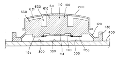
図3、図4、および図5は、図1,図2に示すカメラのシャッタボタン18を示す、それぞれ上面図、図3の矢印X−Xに沿う断面図、および底面図である。
【0035】
このシャッタボタン18は、本発明の二段押ボタンの第一実施形態であり、本発明にいう弾性体の一例であるゴム体100と、本発明にいう剛体のキャップの一例である金属キャップ200とから構成されている。また、ゴム体100は成型品であり、ブロック部110と、スカート部120と、支持部130とから構成されている。
【0036】
そのゴム体100のブロック部110は、略円柱形状のものであり、その上面111が金属キャップ200を介して指で押されることが予定されたものである。
【0037】
また、そのゴム体100のスカート部120は、その上端121がブロック部110の側面112の下部に繋がり、そのブロック部110から離れる方向に斜め下に板状に広がってそのブロック部110の下面113を取り巻く形状のものであり、このスカート部120は、ブロック部110が押下されたときに変形してその押下によるブロック部110の下方への移動を許容するとともにブロック部110の押圧力の消失により変形が回復してブロック部110を持ち上げる作用をなすものである。
【0038】
また、ゴム体100の支持部130は、スカート部120の下端に繋がってそのスカート部120を取り巻き、所定の平面上(例えば図示しない回路基板上)に置かれたときに、ブロック部110の下面113を、その平面から所定の高さに浮いた状態に支持するものである。
【0039】
ここで、ゴム体100のブロック部110は、そのブロック部110の下面中央に形成された、下方に向けて突出した第一の突起部114と、そのブロック部110の下面に、第一の突起部114を取り巻くように3個以上(ここに示す実施形態では4個)形成された、下方に向けて突出した第二の突起部115とを有する。これらの第二の突起部115は、中央に形成された第一の突起部114よりも大きな突出量を有する。すなわち、これらの第二の突起部115はその下面が第一の突起部114の下面よりも下に位置している。
【0040】
また、ブロック部110には、さらに、第二の突起部115のそれぞれに対応した位置に、そのブロック部110の上面111に開口し、その上面側から抉られた形状の穴部116が設けられている。これらの穴部116は、第二の突起部115の径よりも広径であって、その穴部116の底面とブロック部110の下面113との間に所定の厚さのゴム板部117を形成している。
【0041】
ゴム体100の支持部130が所定の平面上(例えば回路基板上)に置かれてそのゴム体100のブロック部110が押下されると、前述したようにスカート部120が変形して、第二の突起部115の方が第一の突起部114よりも下方への突出量が大きいため先ず第二の突起部115がその平面に当接するが、そのブロック部110をさらに強く押すと今度はゴム板部117が変形して第一の突起部114がその平面に当接するまでそのブロック部110のさらなる押下が許容される。ブロック部110への押圧を緩めるとゴム板部117の変形が回復して、第一の突起部114が平面から持ち上がり第二の突起部115のみがその平面に当接した状態となる。ブロック部110への押圧力をさらに緩めると(典型的にはこのシャッタボタン18から指を離すと)スカート部120の変形も回復しブロック部110の全体が持ち上がって第二の突起部115もその平面から離れた状態となる。
【0042】
ここで、本実施形態では、第一の突起部114の下面と、4つの第二の突起部115のうちの、図5に網掛けで示す2つの第二の突起部115aの下面は導電性を有するものである。他の2つの第二の突起部115bの下面は導電性は付与されていない。あるいはその2つの第二の突起部115bに導電性は付与されていても、そこには後述する回路基板上の接点は配置されておらず、接点として意味はなく、支えとしてのみ作用する。
【0043】
また、金属キャップ200は、ゴム体100のブロック部110を、そのブロック部110の上面111から側面112にかけて覆っている。
【0044】
図6、図7は、第一の突起部および第二の突起部への導電性の付与方法の各一例を示す図である。ここでは第一の突起部で代表させて図示してある。
【0045】
図6では、第一の突起部114の下面にシルク印刷された導電性材料からなる電極118が示されている。また、図7には、第一の突起部114の下面に図1〜図3に示すゴム体100と一体的に二重成型により形成された導電性材料による電極119が示されている。
【0046】
これらの例のほか、図1〜図3に示すゴム体100の全体が導電性ゴムで成型されるものであってもよい。
【0047】
図8,図9は、第一の突起部下面および第ニの突起部下面がそれぞれ独立した(相互に電気的に導通していない)導電性が付与されたものである場合に適合する回路基板側の接点の各形状を示す図である。
【0048】
図3〜図5に示すシャッタボタン18は、所定の回路基板上に配置され、その回路基板上の、第一の突起部および第ニの突起部(図5に示す2つの第ニの突起部115a)に対応した位置に、ここに示す形状の電気接点300が配置される。
【0049】
図8,図9のいずれの形状の電気接点においても、その上に第一の突起部114あるいは第ニの突起部115aが接触すると2つの端子301,302の間が導通する。これにより第一の突起部114あるいは第ニの突起部115aによるスイッチのオン/オフが検出される。
【0050】
図10から図12は、シャッタボタン18の押下の各段階を示した断面図であり、図10は、シャッタボタン18から指が離れている状態、図11はシャッタボタン18を指である程度の強さで押下し一段目のスイッチがオンしている状態、図12は、シャッタボタン18をさらに強く押下し、二段目のスイッチがオンしている状態を示している。
【0051】
このシャッタボタン18は、回路基板400上に、ゴム体100の支持部130が固定された状態にある。また、回路基板400上の、第一の突起部114および2つの第二の突起部115aのそれぞれに対応した位置には、図8あるいは図9に示す形状の電気接点300が形成されている。また、第一の突起部114および2つの第二の突起部115aそれぞれの下面には、図6あるいは図7に示すようにして各突起部ごとに独立した導電層が形成されている。
【0052】
ここで、図10に示す、シャッタボタン18の押下開始前の状態から、その頭部(金属キャップ200)が指で押されると、図11に示すように、スカート部120が変形して第二の突起部115が回路基板400に当接し、第二の突起部115aに対応する電気接点300を構成する2つの端子301,302が電気的につながり、電気接点300がオン状態となる。
【0053】
次に、そのシャッタボタン18をさらに強く押すと、図12に示すように、スカート部120がさらに変形するとともに、今度はゴム板部117が変形して第一の突起部114が回路基板400に当接し、その第一の突起部114に対応する電気接点300がオン状態となる。
【0054】
図12に示す状態で指の力を少し緩めると図11に示す状態に戻り、さらに、そのシャッタボタン18から指を離すと、図10に示す状態に戻る。
【0055】
ここで、図3に示す4つの穴部116のうちの左右2つの穴部116aのみが設けられ、残り2つの穴部116bが設けられていない場合を考える。この場合、ゴム体の、図3の左右方向の剛性と図3の上下方向の剛性が異なることになり、シャッタボタン18が少し斜めに押されるとそのシャッタボタンの頭部が倒れる方向に回動してしまい、操作感の悪いシャッタボタンとなってしまう恐れがある。また、単なる操作感の悪さに留まらず、第二の突起部115が回路基板に当接した後、そのシャッタボタン18を強く押したつもりが単に倒れる方向に回動したのみで第一の突起部114が回路基板に正しく当接せず、第一の突起部114に対応する電気接点がオンにならず、シャッタチャンスを逃がすおそれがある。
【0056】
これに対し、本実施形態では、穴部116は、第一の突起部114を取り巻くように4つ設けられているため、そのシャッタボタンの、図3の上下方向と図3の左右方向の剛性が同じになり、シャッタボタン18が仮に少し斜めに押された場合であっても電気接点が確実にオンとなり、安定した動作が行なわれる。
【0057】
尚、本実施形態では穴部116(および第二の突起部)は4個設けられているが、動作が安定するという点に関しては、穴部116(および第二の突起部)は、4個に限られたものではなく、3個以上設けられていればよい。すなわち、4個に限られず、3個、あるいは5個、6個等であってもよい。
【0058】
また、上記実施形態では、第一の突起部及び第二の突起部の下面が導電性である旨説明したが、これは必ずしも必要な要件ではない。例えば、回路基板上の第一の突起部及び第二の突起部に対応した位置に機械的な接点を持ったスイッチやそのほか押圧力でオンになるスイッチを配設したときは、第一の突起部および第二の突起部は回路基板上を押圧するものであればよく、導電性は不要となる。
【0059】
上記実施形態は、ボタン平面形状が円形のものとして記載しているが、楕円形もしくは矩形状等々、デザインに合わせて自在に選択することができる。
【0060】
さらに、上記実施形態は、本発明の二段押ボタンをカメラのシャッタボタンとして用いた例であるが、本発明の二段押ボタンはカメラのシャッタボタンに限らず、二段の押ボタンとして使用するあらゆる用途に適合するものである。
【0061】
図13〜図17は、本発明の二段押ボタンの第二実施形態を示す、それぞれ、金属キャップの一部分の斜視図、ゴム体の一部分の斜視図、ゴム体の上面図、ゴム体に金属キャップが被冠された状態の、図15の矢印X−Xに沿う方向の断面図、および、ゴム体の底面図である。
【0062】
ここでは、図3〜図12を参照して説明した第一実施形態の二段押ボタンの構成要素と同一の構成要素には、その第一実施形態の各図に付した符号と同一の符合を付して示し、第一実施形態との相違点を中心に説明する。
【0063】
図13〜図17に示す第二実施形態の二段押ボタンは、図13に示す形状の金属キャップ200と、図14に示す形状のゴム体100とから構成されている。前述した第一実施形態と同様、ゴム体100は成型品であって、ブロック部110と、スカート部120と、支持部130とから構成されている。スカート部120および支持部130は前述の第一実施形態におけるスカート部および支持部と同様であり、説明は省略する。
【0064】
また、ゴム体100のブロック部110は、第一実施形態と同様、そのブロック部110の下面中央に形成された、下方に向けて突出した第一の突起部114と、そのブロック部110の下面に、第一の突起部114を取り巻くように3個以上(ここに示す実施形態では4個)形成された、下方に向けて突出した第二の突起部115とを有する。これらの第二の突起部115は、中央に形成された第一の突起部114よりも大きな突出量を有する。すなわち、これらの第二の突起部115はその下面が第一の突起部114の下面よりも下に位置している。
【0065】
また、前述の第一実施形態とは異なる点として、この第二実施形態のゴム体100のブロック部110は、さらに、上面511が金属キャップ200に接する(図16参照)中央部510と、上面に開口し中央部510を取り巻くように抉られた形状の溝520を挟んで中央部510を取り巻き、上面531が金属キャップ200から離間してなる取巻部530と、取巻部530をさらに取り巻き、上面551が金属キャップ200に接する周縁部550とを有する。さらに、この第二実施形態では、周縁部550は、上面に開口を有し巻取部530を取り巻くように抉られた形状の第二の溝540を挟んで取巻部530を取り巻くものである。
【0066】
また、この第二実施形態においても、前述の第一実施形態と同様、第一の突起部114の下面と、4つの第二の突起部115のうちの、図17に網掛けで示す2つの第二の突起部115aの下面は導電性を有するものである。他の2つの第二の突起部115bの下面は導電性は付与されていない。あるいはその2つの第二の突起部115bに導電性は付与されていても、そこには後述する回路基板上の接点は配置されておらず、接点として意味はなく、支えとしてのみ作用するものである。第一の突起部114および第二の突起部115への導電性の付与方法、および回路基板上の電気接点の形状等は前述の第一実施形態の場合と同様であり、重複説明は省略する。
【0067】
また、金属キャップ200は、ゴム体100のブロック部110を、そのブロック部110の上面111から側面112にかけて覆っている。
【0068】
図18から図20は、第二実施形態の二段押ボタンの押下の各段階を示した断面図であり、図18は、二段押ボタンから指が離れている状態、図19は二段押ボタンを指である程度の強さで押下し一段目のスイッチがオンしている状態、図20は、二段押ボタンをさらに強く押下し、二段目のスイッチがオンしている状態を示している。この二段押ボタンの押下に伴う動作は、基本的には、前述の第一実施形態における動作と同様であるが、以下にその概要を説明する。
【0069】
この二段押ボタンは、回路基板400上に、ゴム体100の支持部130が固定された状態にある。また、回路基板400上の、第一の突起部114および2つの第二の突起部115aのそれぞれに対応した位置には、図8あるいは図9に示す形状の電気接点300が形成されている。また、第一の突起部114および2つの第二の突起部115aそれぞれの下面には、図6あるいは図7に示すようにして各突起部ごとに独立した導電層が形成されている。
【0070】
ここで、図18に示す、二段押ボタンの押下開始前の状態から、その頭部(金属キャップ200)が指で押されると、図19に示すように、スカート部120が変形して第二の突起部115が回路基板400に当接し、第二の突起部115aに対応する電気接点300を構成する2つの端子301,302(図8,図9参照)が電気的につながり、電気接点300がオン状態となる。
【0071】
次に、その二段押ボタンをさらに強く押すと、図20に示すように、スカート部120がさらに変形するとともに、今度は2つの溝520,540の底部を形成するゴム板部521,541も変形して第一の突起部114が回路基板400に当接し、その第一の突起部114に対応する電気接点300がオン状態となる。
【0072】
図20に示す状態で指の力を少し緩めると図19に示す状態に戻り、さらに、その二段押ボタンから指を離すと、図18に示す状態に戻る。
【0073】
このように、この第二実施形態の二段押ボタンの押下に伴う動作は前述の第1の実施形態の場合とほぼ同様であるが、この第二実施形態の場合、2つの溝520,500の底部を形成するゴム板部521,541の厚さ等を適切に設定することにより、第一実施形態の場合よりも、一段目の接点導通時(図19に示す段階)と二段目の接点導通時(図20に示す段階)の各段において、各段を識別することができる官能を、押下した指先に一層明瞭に伝えることができる。
【0074】
図21〜図23は、本発明の第三実施形態の二段押ボタンの押下の各段階を示した断面図であり、図21は、二段押ボタンから指が離れている状態、図22は、二段押ボタンを指である程度の強さで押下し一段目のスイッチがオンしている状態、図23は、二段押ボタンをさらに強く押下し、二段目のスイッチがオンしている状態を示している。
【0075】
これら図21〜図23に示す第三実施形態の二段押ボタンは、図13〜図20を参照して説明した第二実施形態の二段押ボタンと構造が近似しており、相違点は、図13〜図20に示す第二実施形態のゴム体100のブロック部110に設けられていた第二の溝540が、図21〜図23に示す第三実施形態では省略されている点である。
【0076】
この第三実施形態の二段押ボタンの押下に伴う動作は図18〜図20を参照して説明した第二実施形態の二段押ボタンの押下に伴う動作と同様であり、重複説明は省略する。
【0077】
この第三実施形態の二段押ボタンの場合も、第二実施形態の二段押ボタンと同様、各段を明瞭に指先に伝え、ボタンの操作者が一段目と二段目をはっきりと認識することができる。
【0078】
図24〜図30は、本発明の二段押ボタンの第四実施形態を示す、それぞれ、金属キャップの一部分の斜視図(図24)、ゴム体の一部分の斜視図(図25)、ばね板の斜視図(図26)、ゴム体の上面図(図27)、ゴム体に金属キャップが被冠され、さらにばね板が固定された状態の、図27および図30に示す矢印X−Xに沿う断面図(図28)、図28と同様に、ゴム体に金属キャップが被冠され,さらにばね板が固定された状態の、図27および図30に示す矢印Y−Yに沿う断面図(図29)、および、ゴム体にばね板が固定された状態の底面図である。
【0079】
前述の第二実施形態および第三実施形態の場合と同様、ここでも図3〜図12を参照して説明した第一実施形態の構成要素と同一の構成要素には、その第一実施形態の各図に付した符号と同一の符号を付して示し、第1実施形態との相違点を中心に説明する。
【0080】
図24〜図30に示す第四実施形態の二段押ボタンは、図24に示す形状の金属キャップ200と、図25に示す形状のゴム体100と、さらに図26に示す形状のばね板700とから構成されている、前述した第1実施形態と同様、ゴム体100は、成型品であって、ブロック部110と、スカート部120と、支持部130とから構成されている。スカート部120および支持部130については、前述の第一実施形態におけるスカート部および支持部と同様であり、説明は省略する。
【0081】
また、ゴム体100のブロック部110は、第一実施形態と同様、そのブロック部110の下面中央に形成された、下方に向けて突出した第一の突起部114と、そのブロック部110の下面に、第一の突起部114を取り巻くように3個以上(ここに示す実施形態では4個)形成された、下方に向けて突出した第二の突起部115とを有する。ただし、この第四実施形態では、第一の突起部114の下面に図26に示す形状のばね板700が固定されるが、第二の突起部115は、中央に形成された第一の突起部114の突出量にさらにばね板700の厚みを加えた突出量よりも大きな突出量を有する。すなわち、これらの第二の突起部115はその下面が第一の突起部114の下面に固定されたばね板700の下面よりも下に位置している(図28、図29参照)。
【0082】
また、前述の第1実施形態とは異なる点として、この第四実施形態のゴム体100のブロック部110は、上面611が金属キャップ200に接する中央部600と、上面に開口し中央部600を取り巻くように抉られた形状の溝620を挟んでその中央部600を取り巻き、上面631が金属キャップ200から離間してなる取巻部630とを有するものである。
【0083】
さらに、この第四実施形態の二段押ボタンは、第一の突起部114の下面に固定されたばね板700を備えたものである。
【0084】
ここで、このばね板700は、図26に示すように、第一の突起部114の下面に固定されるとともにその下面の周縁からさらに食み出して広がる、上方に凸の曲面の中央部710と、その中央部710との間に変曲線720をもってさらに広がる、回転対称に形成された少なくとも3つ以上(本実施形態では4つ)の裾部730とを有するものである。
【0085】
ここで、ゴム体100の第ニの突起部115は、第一の突起部114の底面に固定されたばね板700の裾部730の下面よりもさらに下方にまで突出してなるものである。
【0086】
さらに、このばね板700は、本実施形態では金属性であって導電性を有するものであり、また、4つ形成されて第二の突起部115のうちの少なくとも1つ(本実施形態では、図30に網線を付して示す2つ)の第二の突起部115aも導電性を有するものである。
【0087】
本実施形態において、図30に示す他の2つの第二の突起部115bの下面は導電性は付与されていない。あるいはその2つの第二の突起部115bに導電性は付与されていても、そこには後述する回路基板上の接点は配置されておらず、接点として意味はなく、支えとしてのみ作用する。
【0088】
第二の突起部115への導電性の付与方法、および回路基板上の電気接点の形状等は、前述の第一実施形態の場合と同様であり、重複説明は省略する。
【0089】
また、金属キャップ200は、ゴム体100のブロック部110を、そのブロック部110の上面111から側面112にかけて覆っている。
【0090】
図31から図33は、第四実施形態の二段押ボタンの押下の各段階を示した断面図であり、図31は、二段押ボタンから指が離れている状態、図32は二段押ボタンを指である程度の強さで押下し一段目のスイッチがオンしている状態、図33は、二段押ボタンをさらに強く押下し、二段目のスイッチがオンしている状態を示している。
【0091】
この二段押ボタンは、回路基板400上に、ゴム体100の支持部130が固定された状態にある。また、回路基板400上の、第一の突起部114および2つの第二の突起部115aのそれぞれに対応した位置には、図8あるいは図9に示す形状の電気接点300が形成されている。また、第一の突起部114の下面には導電性のばね板700が固定されており、2つの第二の突起部115aの下面には、図6あるいは図7に示すようにして各突部ごとに独立した導電層が形成されている。
【0092】
ここで、図31に示す、二段押ボタンの押下開始前の状態から、その頭部(金属キャップ200)が指で押されると、図32に示すように、スカート部120が変形して第二の突起部115が回路基板400に当接し、第二の突起部115aに対応する電気接点300を構成する2つの端子301,302が電気的につながり、電気接点300がオン状態となる。
【0093】
次に、その二段押ボタンをさらに強く押すと、スカート部120がさらに変形するとともに、今度はブロック部110の全体が、図33の一点鎖線に示すように変形して、ばね板700の、先ずは裾部730(図26参照)が回路基板400に接触し、さらなる押下によりそのばね板700の中央部710も変形して回路基板400に接触するとともに、第一の突起部114に対応する電気接点300がオン状態となる。
【0094】
図33に示す状態で指の力を緩めると図32に示す状態に戻り、さらに、その二段押ボタンから指を離すと、図31に示す状態に戻る。
【0095】
この第四実施形態の二段押ボタンの場合、ばね板の厚さや形状等を適切に設定することにより、第一実施形態の場合よりも、さらには、第二実施形態あるいは第三実施形態の場合よりも、各段におけるクリック感を一層明確に指先に伝えることができ、ばね板700という部品は増えるものの、クリック感を極めてはっきりと指先に伝える二段押ボタンを構成することができる。
【0096】
【発明の効果】
以上説明したように、本発明によれば、斜めに押されたときの許容度が大きく、正確に動作する二段押ボタンが実現する。
【図面の簡単な説明】
【図1】本発明の二段押ボタンの一実施形態としてのシャッタボタンを備えたカメラを、正面斜めから見て示す外観斜視図である。
【図2】図1のカメラを背面斜め上から見て示す外観斜視図である。
【図3】図1,図2に示すカメラのシャッタボタンを示す上面図である。
【図4】図1,図2に示すカメラのシャッタボタンを示す、図3の矢印X−Xに沿う断面図である。
【図5】図1,図2に示すカメラのシャッタボタンを示す底面図である。
【図6】第一の突起部、第ニの突起部への導電性の付与方法の一例を示す図である。
【図7】第一の突起部、第ニの突起部への導電性の付与方法の他の例を示す図である。
【図8】第一の突起部下面および第ニの突起部下面がそれぞれ独立した(相互に電気的に導通していない)導電性が付与されたものである場合に適合する回路基板側の接点の形状を示す図である。
【図9】第一の突起部および第ニの突起部がそれぞれ独立した(相互に電気的に導通していない)導電性が付与されたものである場合に適合する回路基板側の接点の形状を示す図である。
【図10】押下前のシャッタボタンを示した断面図である。
【図11】一段押された状態のシャッタボタンを示した断面図である。
【図12】二段段押された状態のシャッタボタンを示した断面図である。
【図13】本発明の二段押ボタンの第二実施形態を構成する金属キャップの一部分の斜視図である。
【図14】本発明の二段押ボタンの第二実施形態を構成するゴム体の一部分の斜視図である。
【図15】本発明の二段押ボタンの第二実施形態を構成するゴム体の上面図である。
【図16】本発明の二段押ボタンの第二実施形態を構成するゴム体に金属キャップが被冠された状態の、図15の矢印X−Xに沿う方向の断面図である。
【図17】本発明の二段押ボタンの第二実施形態を構成するゴム体の底面図である。
【図18】第二実施形態の二段押ボタンから指が離れている状態を示した断面図である。
【図19】第二実施形態の二段押ボタンを指である程度の強さで押下し一段目のスイッチがオンしている状態を示した断面図である。
【図20】第二実施形態の二段押ボタンをさらに強く押下し、二段目のスイッチがオンしている状態を示した断面図である。
【図21】本発明の第三実施形態の二段押ボタンから指が離れている状態を示す図である。
【図22】本発明の第三実施形態の二段押ボタンを指である程度の強さで押下し、一段目のスイッチがオンしている状態を示す図である。
【図23】本発明の第三実施形態の二段押ボタンをさらに強く押下し、二段目のスイッチがオンしている状態を示す図である。
【図24】本発明の二段押ボタンの第四実施形態を構成する金属キャップの一部分の斜視図である。
【図25】本発明の二段押ボタンの第四実施形態を構成するゴム体の一部分の斜視図である。
【図26】本発明の二段押ボタンの第四実施形態を構成するばね板の斜視図である。
【図27】本発明の二段押ボタンの第四実施形態を構成するゴム体の上面図である。
【図28】本発明の二段押ボタンの第四実施形態を構成するゴム体に金属キャップが被冠され、さらにばね板が固定された状態の、図27および図30に示す矢印X−Xに沿う断面図である。
【図29】本発明の二段押ボタンの第四実施形態を構成するゴム体に金属キャップが被冠され、さらにばね板が固定された状態の、図27および図30に示す矢印Y−Yに沿う断面図である。
【図30】本発明の二段押ボタンの第四実施形態を構成するゴム体にばね板が固定された状態の底面図である。
【図31】第四実施形態の二段押ボタンから指が離れている状態を示した断面図である。
【図32】第四実施形態の二段押ボタンを指である程度の強さで押下し、一段目のスイッチがオンしている状態を示した断面図である。
【図33】第四実施形態の二段押ボタンをさらに強く押下し、二段目のスイッチがオンしている状態を示した断面図である。
【符号の説明】
10 カメラ
18 シャッタボタン
100 ゴム体
110 ブロック部
111 上面
112 側面
113 下面
114 第一の突起部
115 第二の突起部
116 穴部
117 ゴム板部
120 スカート部
121 上端
130 支持部
200 金属キャップ
300 電気接点
301,302 端子
400 回路基板
510 中央部
511 上面
520 溝
521 ゴム板部
530 取巻部
531 上面
540 第二の溝
541 ゴム板部
550 周縁部
551 上面
610 中央部
611 上面
620 溝
630 取巻部
631 上面
700 ばね板
710 中央部
720 変曲線
730 裾部[0001]
BACKGROUND OF THE INVENTION
The present invention relates to a two-stage pushbutton that is pushed in two stages.
[0002]
[Prior art]
In various devices with built-in electronic circuits, a two-step operation is performed in which some operation is prepared in response to a human operation, and the operation that has been prepared is actually performed in the next operation following the operation. In such cases, a two-stage pushbutton may be used.
[0003]
For example, such a two-stage push button is adopted as a shutter button of a compact camera. When this shutter button is pressed in one step, distance measurement for measuring the distance to the subject, photometry for measuring the brightness of the subject, and the like are performed, and the shutter speed and the like are calculated internally based on the distance measurement. Shooting is performed at the shutter speed obtained by the calculation at the timing when the button is pushed one more stage.
[0004]
[Problems to be solved by the invention]
There are various requirements for the two-stage push button such as the shutter button, such that the first and second stages can be clearly recognized as if they were pressed with a finger, the cost is low, and the appearance is beautiful. Although there is a requirement, more essential, it is necessary to reliably satisfy the requirement that the contact is properly entered (turned on) in the first and second stages.
[0005]
In many cases, a molded product of an elastic body such as rubber is used as the push button as described above. In that case, a special device is required to make a two-stage push button. Although the product is deformed even if it is pushed slightly diagonally, the conventional device works correctly when pushed accurately from above, but when pushed diagonally, for example, the first step works correctly, but the second step In some cases, the contact may not be turned on, or when pressed obliquely, the push button may not be pressed correctly and may move in the rotational direction, causing problems in basic operation as a push button.
[0006]
It is an object of the present invention to provide a two-stage pushbutton that operates accurately and has a high tolerance when pressed obliquely.
[0007]
[Means for Solving the Problems]
Of the two-stage pushbuttons of the present invention that achieve the above object, the first two-stage pushbutton is:
The block part where the upper surface is pushed and the upper end are connected to the lower part of the side surface of the block part, spread in a plate shape diagonally downward in the direction away from the block part, and surround the lower surface of the block part. A skirt part that allows the block part to be moved downward by pressing and recovers deformation due to the loss of the pressing force to the block part, and lifts the block part. An elastic body having a support portion for supporting the lower surface of the block portion in a floating state when placed on the surface, and
A rigid cap that covers at least the upper surface of the elastic block;
Three or more block portions of the elastic body are formed at the center of the lower surface of the block portion, projecting downward, and three or more so as to surround the first protrusion portion on the lower surface of the block portion. With the formed second protrusion having a larger protrusion amount than the first protrusion,
The block portion is further formed at a position corresponding to each of the second protrusions, and opens on the upper surface of the block portion, leaving a rubber plate portion having a predetermined thickness between the bottom surface and the lower surface of the block portion. It is characterized by having three or more hole portions of the shape that has been beaten.
[0008]
Here, in the first two-stage push button, the lower surface of the first protrusion has conductivity, and the lower surface of at least one second protrusion of the second protrusion has conductivity. It is preferable.
[0009]
The second two-stage pushbutton of the two-stage pushbutton according to the present invention has a block portion whose upper surface is pushed and an upper end connected to the lower portion of the side surface of the block portion, and is inclined diagonally downward in a direction away from the block portion. It spreads in the shape of a block and surrounds the lower surface of the block part, deforms when the block part is pressed down, allows downward movement of the block part by the pressing, and recovers deformation due to the disappearance of the pressing force to the block part. Elasticity having a skirt part for lifting the part and a support part connected to the lower end of the skirt part to surround the skirt part and support the lower surface of the block part at a predetermined height when placed on a predetermined plane Body, and
A rigid cap that covers at least the upper surface of the elastic block;
Three or more block portions of the elastic body are formed at the center of the lower surface of the block portion, projecting downward, and three or more so as to surround the first protrusion portion on the lower surface of the block portion. With the formed second protrusion having a larger protrusion amount than the first protrusion,
The block portion further includes a central portion where the upper surface is in contact with the cap, and a winding portion which surrounds the central portion with a groove formed so as to open to the upper surface and surround the central portion, and the upper surface is separated from the cap. And a winding part is further wound, and the upper surface has a peripheral part in contact with the cap.
[0010]
Here, in the second two-stage push button, the peripheral portion surrounds the winding portion with a second groove having a shape having an opening on the upper surface and wound around the winding portion. It is also a preferred embodiment.
[0011]
Further, in the second two-stage push button, the lower surface of the first protrusion has conductivity, and at least one second of the second protrusions is the same as the first two-stage push button. It is preferable that the lower surface of the projection has conductivity.
[0012]
The third two-stage push button of the two-stage push button according to the present invention has a block portion whose upper surface is pressed and an upper end that is connected to the lower portion of the side surface of the block portion, and has a plate shape obliquely downward in a direction away from the block portion It spreads around and surrounds the lower surface of the block part, deforms when the block part is pressed down, allows downward movement of the block part due to the pressing, and recovers deformation due to the disappearance of the pressing force to the block part. An elastic body having a skirt portion for lifting the skirt portion and a support portion that is connected to the lower end of the skirt portion, surrounds the skirt portion, and supports the lower surface of the block portion at a predetermined height when placed on a predetermined plane ,and
A rigid cap that covers at least the upper surface of the elastic block;
Three or more block portions of the elastic body are formed at the center of the lower surface of the block portion, projecting downward, and three or more so as to surround the first protrusion portion on the lower surface of the block portion. With the formed second protrusion having a larger protrusion amount than the first protrusion,
The winding further comprises a central portion where the upper surface is in contact with the cap and a groove having a shape that is open to the upper surface and is wound around the central portion. And further comprising
A spring plate fixed to the lower surface of the first protrusion is provided.
[0013]
Here, in the third two-stage pushbutton, the spring plate is fixed to the lower surface of the first protrusion and further protrudes and spreads from the periphery of the lower surface, and the center portion of the upward convex curved surface And at least three or more hems formed in a rotationally symmetrical manner that further expands with a curved line between the central part and the center part. It is preferable that the spring plate protrudes further downward than the bottom surface of the hem portion.
[0014]
In the third two-stage push button, the spring plate has conductivity, and the lower surface of at least one second projection of the second projection has conductivity. It is preferable that
[0015]
In the present invention, the two-stage push button can also be understood as the following aspects (1) to (10).
[0016]
(1) A button formed of an elastic material that is depressed when a pressure is applied to the upper surface and is automatically restored when the pressure is removed, the cap having a top surface and a side circumferential surface formed of a thin rigid body. It has a skirt-shaped thin wall portion that is covered and extends obliquely downward at the lower peripheral edge of the button, and at least three or more squeezed from the upper surface of the button so as to have an even positional relationship in a plane. Forming a bag-like hole, and forming a first protrusion at the center of the button on the lower surface of the button, and corresponding to the hole so as to surround the first protrusion; A two-stage pushbutton characterized in that a second protrusion having a height higher than that of the protrusion and having the same height is formed, and none of these protrusions protrudes from the skirt-shaped hem. .
[0017]
(2) The lower surface of the first protruding portion has conductivity, and the lower surface of at least one second protruding portion of the second protruding portion has conductivity. 1) The two-stage push button described.
[0018]
(3) A button that is depressed when a pressing force is applied and that automatically recovers when the pressing force is removed, and is formed on the upper surface of the button that is formed of an elastic body that is covered with a thin rigid body on the upper surface and side peripheral surface. And the side peripheral wall is made higher than the surrounding so as to be in contact with the rigid body, except for the central part and the side peripheral wall, the rigid body is provided with a gap and provided with at least one donut-shaped hole with a closed bottom surface, The first protrusion is integrally formed at the center of the lower surface of the button, and is located outside and corresponding to the ring-shaped thick portion other than the donut-shaped hole, and having a planar planar positional relationship. A second protrusion is formed, a skirt-shaped thin part is formed on the lower side of the side peripheral wall obliquely outward and downward, and a support part is integrally formed. The thickness of the bottom of the skirt-shaped part The first stage switch is obtained by deformation of the thin skirt-shaped part, and the second stage switch is obtained by deformation of the bottom surface of the donut-shaped hole. button.
[0019]
(4) The two-stage push button according to (3), wherein there are at least three second protrusions.
[0020]
(5) The lower surface of the first protruding portion has conductivity, and the lower surface of at least one second protruding portion of the second protruding portions has conductivity. 3) The two-stage pushbutton described.
[0021]
(6) A button that is pressed down when a pressing force is applied, and that automatically returns when the pressing force is removed, and is formed on the upper surface of the button that is formed of an elastic body that is covered with a thin rigid body on the upper surface and side peripheral surface. Is made higher than the surroundings so as to be in contact with the rigid body, the periphery has a gap with respect to the rigid body, and a hole is provided between the central portion and the first protrusion on the lower surface central portion of the button. A spring plate is formed by integrally forming it, and at least two or more second protrusions are integrally provided around the periphery, and a thin skirt-shaped portion is integrally formed downward on the outer periphery of the lower side of the button, Further, the support part is formed integrally with the skirt-shaped part, the first-stage switch is obtained by deformation of the skirt-shaped part, and the second-stage switch is obtained by deformation of the spring plate. Step push button.
[0022]
(7) The spring plate has a curved surface whose central portion is loose in the push-down direction, and has a hem portion having an equal positional relationship in a plane around the spring plate. The two-stage pushbutton as set forth in (6), wherein the space forms an inflection point, and the area of the first protrusion is smaller than the area occupied by the curved surface.
[0023]
(8) The skirt portion of the spring plate is configured such that the second protrusion comes into contact with the substrate prior to contact with the substrate provided opposite to the button in use (6). Or the two-stage pushbutton as described in (7).
[0024]
(9) The two-stage pushbutton according to any one of (6) to (8), wherein at least three or more of the second protrusions are formed at positions that are planarly uniform.
[0025]
(10) The spring plate has conductivity, and at least one second projection of the second projection has conductivity. (6) (2) The two-stage pushbutton as described in any one of.
[0026]
DETAILED DESCRIPTION OF THE INVENTION
Hereinafter, embodiments of the present invention will be described.
[0027]
FIG. 1 is an external perspective view showing a camera provided with a shutter button as an embodiment of the two-stage pushbutton of the present invention when viewed obliquely from the front.
[0028]
A
[0029]
Further, a
[0030]
Further, a
[0031]
Further, a hop-up strobe
[0032]
FIG. 2 is an external perspective view showing the camera of FIG.
[0033]
On the rear side of the
[0034]
3, 4, and 5 are a top view, a cross-sectional view taken along arrows XX in FIG. 3, and a bottom view, respectively, showing the
[0035]
The
[0036]
The
[0037]
The
[0038]
Further, the
[0039]
Here, the
[0040]
Further, the
[0041]
When the
[0042]
Here, in the present embodiment, the lower surface of the
[0043]
The
[0044]
6 and 7 are diagrams illustrating examples of methods for imparting conductivity to the first protrusion and the second protrusion. Here, the first protrusion is shown as a representative.
[0045]
FIG. 6 shows an
[0046]
In addition to these examples, the
[0047]
FIGS. 8 and 9 are circuit boards that are suitable when the first projecting portion lower surface and the second projecting portion lower surface are provided with independent conductivity (not electrically connected to each other). It is a figure which shows each shape of the contact of a side.
[0048]
The
[0049]
8 and 9, when the
[0050]
10 to 12 are cross-sectional views showing the steps of pressing the
[0051]
The
[0052]
Here, when the head (metal cap 200) is pressed with a finger from the state before the start of pressing the
[0053]
Next, when the
[0054]
When the finger force is slightly relaxed in the state shown in FIG. 12, the state returns to the state shown in FIG. 11, and when the finger is released from the
[0055]
Here, consider a case where only the left and right two holes 116a of the four
[0056]
On the other hand, in the present embodiment, since the four
[0057]
In the present embodiment, four holes 116 (and second protrusions) are provided, but four holes 116 (and second protrusions) are provided in terms of stable operation. The number is not limited to the above, and three or more may be provided. That is, the number is not limited to four, and may be three, five, six, or the like.
[0058]
Moreover, although the said embodiment demonstrated that the lower surface of the 1st projection part and the 2nd projection part was electroconductive, this is not necessarily a requirement. For example, when a switch with a mechanical contact at a position corresponding to the first and second protrusions on the circuit board or a switch that is turned on by pressing force is arranged, the first protrusion The part and the second protrusion need only press the circuit board, and conductivity is not necessary.
[0059]
In the above-described embodiment, the button plane shape is described as a circular shape, but an oval shape, a rectangular shape, or the like can be freely selected according to the design.
[0060]
Furthermore, although the said embodiment is an example which used the two-stage pushbutton of this invention as a shutter button of a camera, the two-stage pushbutton of this invention is used not only as a shutter button of a camera but as a two-stage pushbutton. It is suitable for all uses.
[0061]
FIGS. 13 to 17 show a second embodiment of the two-stage pushbutton of the present invention, respectively, a perspective view of a part of a metal cap, a perspective view of a part of a rubber body, a top view of the rubber body, and a metal in the rubber body. It is sectional drawing of the direction in alignment with the arrow XX of FIG. 15 in the state by which the cap was crowned, and the bottom view of a rubber body.
[0062]
Here, the same components as the components of the two-stage pushbutton of the first embodiment described with reference to FIGS. 3 to 12 are denoted by the same reference numerals as those in the drawings of the first embodiment. The difference from the first embodiment will be mainly described.
[0063]
The two-stage pushbutton of the second embodiment shown in FIGS. 13 to 17 is composed of a
[0064]
Further, the
[0065]
Further, as different from the first embodiment described above, the
[0066]
Also in the second embodiment, as in the first embodiment described above, two of the lower surface of the
[0067]
The
[0068]
18 to 20 are cross-sectional views showing the steps of pressing the two-stage push button according to the second embodiment. FIG. 18 shows a state where a finger is separated from the two-stage push button. FIG. FIG. 20 shows a state where the push button is pressed with a certain amount of strength with a finger and the first switch is turned on, and FIG. 20 shows a state where the second push button is pressed more strongly and the second switch is turned on. ing. The operation accompanying the pressing of the two-stage push button is basically the same as the operation in the first embodiment described above, but the outline thereof will be described below.
[0069]
The two-stage push button is in a state where the
[0070]
Here, when the head (metal cap 200) is pressed with a finger from the state before the start of the pressing of the two-stage push button shown in FIG. 18, the
[0071]
Next, when the two-stage push button is further strongly pressed, as shown in FIG. 20, the
[0072]
When the finger force is slightly loosened in the state shown in FIG. 20, the state returns to the state shown in FIG. 19, and when the finger is released from the two-stage push button, the state returns to the state shown in FIG.
[0073]
Thus, although the operation | movement accompanying pressing of the two-step pushbutton of this 2nd embodiment is as substantially the same as the case of the above-mentioned 1st Embodiment, in this 2nd embodiment, two groove | channels 520,500. By appropriately setting the thicknesses and the like of the
[0074]
21 to 23 are cross-sectional views showing the steps of pressing the two-stage pushbutton according to the third embodiment of the present invention. FIG. 21 shows a state where the finger is separated from the two-stage pushbutton. Is a state where the second-stage push button is pressed with a certain amount of strength with a finger and the first-stage switch is turned on. FIG. 23 shows a state where the second-stage push button is further depressed and the second-stage switch is turned on. It shows the state.
[0075]
The two-stage pushbutton of the third embodiment shown in FIGS. 21 to 23 is similar in structure to the two-stage pushbutton of the second embodiment described with reference to FIGS. 13 to 20. The
[0076]
The operation associated with the pressing of the two-stage push button of the third embodiment is the same as the operation associated with the pressing of the two-stage push button of the second embodiment described with reference to FIGS. To do.
[0077]
In the case of the two-stage pushbutton of the third embodiment, as in the second-stage pushbutton of the second embodiment, each stage is clearly transmitted to the fingertip, and the button operator clearly recognizes the first and second stages. can do.
[0078]
24 to 30 show a fourth embodiment of the two-stage pushbutton of the present invention, respectively, a perspective view of a part of a metal cap (FIG. 24), a perspective view of a part of a rubber body (FIG. 25), and a spring plate. 26, a top view of the rubber body (FIG. 27), and an arrow XX shown in FIGS. 27 and 30 in a state where the rubber body is covered with a metal cap and a spring plate is fixed. Sectional view along FIG. 28 (FIG. 28), Similarly to FIG. 28, a sectional view taken along arrows YY shown in FIG. 27 and FIG. FIG. 29) and a bottom view showing a state in which the spring plate is fixed to the rubber body.
[0079]
As in the case of the second embodiment and the third embodiment described above, the same components as those of the first embodiment described with reference to FIGS. The same reference numerals as those used in the drawings are attached, and the differences from the first embodiment will be mainly described.
[0080]
The two-stage pushbutton of the fourth embodiment shown in FIGS. 24 to 30 includes a
[0081]
Further, the
[0082]
Further, as different from the first embodiment described above, the
[0083]
Further, the two-stage push button of the fourth embodiment includes a
[0084]
Here, as shown in FIG. 26, the
[0085]
Here, the second projecting
[0086]
Furthermore, the
[0087]
In the present embodiment, conductivity is not imparted to the lower surfaces of the other two second protrusions 115b shown in FIG. Alternatively, even if conductivity is imparted to the two second protrusions 115b, a contact point on a circuit board described later is not disposed there, and it has no meaning as a contact point, and acts only as a support.
[0088]
The method of imparting conductivity to the
[0089]
The
[0090]
FIGS. 31 to 33 are cross-sectional views showing the steps of pressing the two-stage push button according to the fourth embodiment. FIG. 31 shows a state where the finger is separated from the two-stage push button, and FIG. FIG. 33 shows a state where the push button is pressed with a finger with a certain degree of strength and the first step switch is turned on, and FIG. 33 shows a state where the second step push button is pushed more strongly and the second step switch is turned on. ing.
[0091]
The two-stage push button is in a state where the
[0092]
Here, when the head (metal cap 200) is pressed with a finger from the state before the start of pressing of the two-stage push button shown in FIG. 31, the
[0093]
Next, when the two-stage push button is pressed more strongly, the
[0094]
When the finger is loosened in the state shown in FIG. 33, the state returns to the state shown in FIG. 32, and when the finger is released from the two-stage push button, the state returns to the state shown in FIG.
[0095]
In the case of the two-stage pushbutton of the fourth embodiment, by appropriately setting the thickness, shape, etc. of the spring plate, the second embodiment or the third embodiment is further improved than the case of the first embodiment. The click feeling at each step can be transmitted to the fingertip more clearly than in the case, and the number of the
[0096]
【The invention's effect】
As described above, according to the present invention, a two-stage push button that has a large tolerance when pressed obliquely and operates accurately is realized.
[Brief description of the drawings]
FIG. 1 is an external perspective view showing a camera provided with a shutter button as an embodiment of a two-stage pushbutton according to the present invention as seen from the front side.
FIG. 2 is an external perspective view showing the camera of FIG.
3 is a top view showing a shutter button of the camera shown in FIGS. 1 and 2. FIG.
4 is a cross-sectional view taken along arrow XX in FIG. 3, showing a shutter button of the camera shown in FIGS. 1 and 2. FIG.
5 is a bottom view showing a shutter button of the camera shown in FIGS. 1 and 2. FIG.
FIG. 6 is a diagram illustrating an example of a method for imparting conductivity to a first protrusion and a second protrusion.
FIG. 7 is a diagram showing another example of a method for imparting conductivity to the first protrusion and the second protrusion.
FIG. 8 is a circuit board-side contact suitable when the lower surface of the first protrusion and the lower surface of the second protrusion are each provided with independent conductivity (not electrically connected to each other). FIG.
FIG. 9 is a circuit board side contact shape suitable when the first protrusion and the second protrusion are provided with independent conductivity (not electrically connected to each other). FIG.
FIG. 10 is a cross-sectional view showing a shutter button before being pressed;
FIG. 11 is a cross-sectional view showing the shutter button in a state where the shutter button is pressed one step.
FIG. 12 is a cross-sectional view showing the shutter button in a state where the shutter button is pressed two steps.
FIG. 13 is a perspective view of a part of a metal cap constituting the second embodiment of the two-stage pushbutton of the present invention.
FIG. 14 is a perspective view of a part of a rubber body constituting a second embodiment of the two-stage pushbutton of the present invention.
FIG. 15 is a top view of a rubber body constituting a second embodiment of the two-stage pushbutton of the present invention.
16 is a cross-sectional view taken along the arrow XX in FIG. 15 in a state in which a metal cap is put on the rubber body constituting the second embodiment of the two-stage pushbutton of the present invention.
FIG. 17 is a bottom view of a rubber body constituting a second embodiment of the two-stage pushbutton of the present invention.
FIG. 18 is a cross-sectional view showing a state where a finger is separated from the two-stage pushbutton of the second embodiment.
FIG. 19 is a cross-sectional view showing a state in which the first-stage switch is turned on by pressing the second-stage pushbutton of the second embodiment with a finger with a certain degree of strength.
FIG. 20 is a cross-sectional view showing a state where the second-stage push button of the second embodiment is pressed more strongly and the second-stage switch is on.
FIG. 21 is a diagram showing a state where a finger is separated from the two-stage push button according to the third embodiment of the present invention.
FIG. 22 is a diagram showing a state where the first-stage switch is turned on by pressing the second-stage pushbutton of the third embodiment of the present invention with a finger with a certain degree of strength.
FIG. 23 is a diagram showing a state in which the second-stage pushbutton of the third embodiment of the present invention is further pressed down and the second-stage switch is turned on.
FIG. 24 is a perspective view of a part of a metal cap constituting the fourth embodiment of the two-stage pushbutton of the present invention.
FIG. 25 is a perspective view of a part of a rubber body constituting a fourth embodiment of the two-stage pushbutton of the present invention.
FIG. 26 is a perspective view of a spring plate constituting a fourth embodiment of the two-stage pushbutton of the present invention.
FIG. 27 is a top view of a rubber body constituting a fourth embodiment of the two-stage pushbutton of the present invention.
FIG. 28 shows arrows XX shown in FIGS. 27 and 30 in a state where a rubber cap constituting a fourth embodiment of the two-stage pushbutton of the present invention is covered with a metal cap and a spring plate is fixed. FIG.
29 shows arrows YY shown in FIGS. 27 and 30 in a state where a metal cap is crowned on a rubber body constituting a fourth embodiment of the two-stage pushbutton of the present invention, and a spring plate is fixed. FIG. FIG.
FIG. 30 is a bottom view showing a state in which a spring plate is fixed to a rubber body constituting a fourth embodiment of the two-stage pushbutton of the present invention.
FIG. 31 is a cross-sectional view showing a state in which a finger is separated from the two-stage pushbutton of the fourth embodiment.
FIG. 32 is a cross-sectional view showing a state in which the first-stage switch is turned on by pressing the second-stage pushbutton of the fourth embodiment with a finger with a certain degree of strength.
FIG. 33 is a cross-sectional view showing a state where the second-stage push button of the fourth embodiment is pressed more strongly and the second-stage switch is on.
[Explanation of symbols]
10 Camera
18 Shutter button
100 Rubber body
110 blocks
111 Upper surface
112 side
113 Bottom
114 First protrusion
115 Second protrusion
116 hole
117 Rubber plate
120 Skirt
121 Top
130 Supporting part
200 Metal cap
300 electrical contacts
301,302 terminals
400 circuit board
510 center
511 Top surface
520 groove
521 Rubber plate
530 winding section
531 Upper surface
540 Second groove
541 Rubber plate
550 peripheral edge
551 Top surface
610 Central
611 Top surface
620 groove
630 winding section
631 Top surface
700 Spring plate
710 Central
720 curve
730 hem
Claims (4)
前記弾性体の前記ブロック部の上面と側周面を覆う剛体のキャップを備え、
前記弾性体の前記ブロック部が、該ブロック部の下面中央に形成された、下方に向けて突出した第一の突起部と、該ブロック部下面に、前記第一の突起部を取り巻くように回転対称に4個形成された、前記第一の突起部よりも突出量の大きな第二の突起部とを有するとともに、
該ブロック部がさらに、前記第二の突起部それぞれに対応した位置に形成された、該ブロック部上面に開口し、その底面と該ブロック部の下面との間に所定の厚さのゴム板部を残して抉られた形状の、前記第二の突起部と同様に回転対称に形成された4個の穴部を有し、該ブロック部の上面が該4個の穴部を除き前記キャップに接するものであることを特徴とする二段押ボタン。A block part whose upper surface is pushed and an upper end are connected to the lower part of the side surface of the block part, spread in a diagonally downward plate shape in a direction away from the block part and surround the lower surface of the block part, and deformed when the block part is pushed. The skirt portion that allows the block portion to be moved downward by the pressing and that recovers deformation due to the loss of the pressing force to the block portion and lifts the block portion, and is connected to the lower end of the skirt portion. An elastic body having a support portion that surrounds the portion and supports the lower surface of the block portion in a state of floating at a predetermined height when placed on a predetermined plane, and an upper surface and a side of the block portion of the elastic body It has a rigid cap that covers the circumference,
The block portion of the elastic body is formed at the center of the bottom surface of the block portion and protrudes downward, and rotates so as to surround the first projection portion on the bottom surface of the block portion. And four symmetrically formed second projections having a larger projection amount than the first projection,
The block portion is further formed at a position corresponding to each of the second protrusions, and is open to the upper surface of the block portion, and a rubber plate portion having a predetermined thickness between the bottom surface and the lower surface of the block portion And has four holes formed in a rotationally symmetric manner like the second protrusions , and the upper surface of the block part is formed on the cap except for the four holes. A two-stage pushbutton characterized by touching .
前記弾性体の前記ブロック部の上面と側周面を覆う剛体のキャップを備え、
前記弾性体の前記ブロック部が、該ブロック部の下面中央に形成された、下方に向けて突出した第一の突起部と、該ブロック部下面に、前記第一の突起部を取り巻くように回転対称に4個形成された、前記第一の突起部よりも突出量の大きな第二の突起部とを有するとともに、
該ブロック部がさらに、上面が前記キャップに接する中央部と、上面に開口し該中央部を取り巻くように抉られた形状の溝を挟んで該中央部を取り巻き、上面が前記キャップから離間してなる取巻部と、該取巻部をさらに取り巻き、上面が前記キャップに接する周縁部とを有するものであることを特徴とする二段押ボタン。A block part whose upper surface is pushed and an upper end are connected to the lower part of the side surface of the block part, spread in a diagonally downward plate shape in a direction away from the block part and surround the lower surface of the block part, and deformed when the block part is pushed. The skirt portion that allows the block portion to be moved downward by the pressing and that recovers deformation due to the loss of the pressing force to the block portion and lifts the block portion, and is connected to the lower end of the skirt portion. An elastic body having a support portion that surrounds the portion and supports the lower surface of the block portion in a state of floating at a predetermined height when placed on a predetermined plane, and an upper surface and a side of the block portion of the elastic body It has a rigid cap that covers the circumference,
The block portion of the elastic body is formed at the center of the bottom surface of the block portion and protrudes downward, and rotates so as to surround the first projection portion on the bottom surface of the block portion. And four symmetrically formed second projections having a larger projection amount than the first projection,
The block further includes a central portion with an upper surface contacting the cap, and a groove having a shape that opens to the upper surface and is wound around the central portion, and surrounds the central portion, and the upper surface is separated from the cap. A two-stage pushbutton characterized by comprising: a surrounding winding portion; and a surrounding portion further surrounding the winding portion and having an upper surface in contact with the cap.
前記第二の突起部のうちの少なくとも1つの第二の突起部の下面が導電性を有するものであることを特徴とする請求項1記載の二段押ボタン。While the lower surface of the first protrusion has conductivity,
2. The two-stage pushbutton according to claim 1, wherein a lower surface of at least one second protrusion of the second protrusions has conductivity.
Priority Applications (1)
| Application Number | Priority Date | Filing Date | Title |
|---|---|---|---|
| JP2000285029A JP4271837B2 (en) | 2000-02-29 | 2000-09-20 | Double push button |
Applications Claiming Priority (3)
| Application Number | Priority Date | Filing Date | Title |
|---|---|---|---|
| JP2000054017 | 2000-02-29 | ||
| JP2000-54017 | 2000-02-29 | ||
| JP2000285029A JP4271837B2 (en) | 2000-02-29 | 2000-09-20 | Double push button |
Publications (3)
| Publication Number | Publication Date |
|---|---|
| JP2001318414A JP2001318414A (en) | 2001-11-16 |
| JP2001318414A5 JP2001318414A5 (en) | 2005-11-04 |
| JP4271837B2 true JP4271837B2 (en) | 2009-06-03 |
Family
ID=26586396
Family Applications (1)
| Application Number | Title | Priority Date | Filing Date |
|---|---|---|---|
| JP2000285029A Expired - Fee Related JP4271837B2 (en) | 2000-02-29 | 2000-09-20 | Double push button |
Country Status (1)
| Country | Link |
|---|---|
| JP (1) | JP4271837B2 (en) |
Families Citing this family (2)
| Publication number | Priority date | Publication date | Assignee | Title |
|---|---|---|---|---|
| JP5978622B2 (en) * | 2011-12-28 | 2016-08-24 | ブラザー工業株式会社 | Rubber key |
| WO2017204341A1 (en) * | 2016-05-27 | 2017-11-30 | ポリマテック・ジャパン株式会社 | Push-button switch |
-
2000
- 2000-09-20 JP JP2000285029A patent/JP4271837B2/en not_active Expired - Fee Related
Also Published As
| Publication number | Publication date |
|---|---|
| JP2001318414A (en) | 2001-11-16 |
Similar Documents
| Publication | Publication Date | Title |
|---|---|---|
| US7368672B2 (en) | Push-on switch | |
| US7217893B1 (en) | Two-stage button structure | |
| JP2010135319A (en) | Multi-stage operation switch | |
| JP4271837B2 (en) | Double push button | |
| US20030021284A1 (en) | Coordinate input apparatus including an optical movement detection device used for optically inputting coordinates and pressed for switching a switch device | |
| JP2000067698A (en) | Switch operating rubber member | |
| JP2011134513A (en) | Two-step switch and imaging device with the same | |
| CA2629690C (en) | Compound operation input device | |
| US20030136650A1 (en) | Two-stage touch switch | |
| JP2000353456A (en) | Multi-direction switch | |
| CN104517766A (en) | Operation key assembly | |
| JPH0234669Y2 (en) | ||
| JP2004007221A (en) | Auto-focus starting mechanism in digital camera | |
| JP3174900B2 (en) | Rotary electronic components with pushbutton switches | |
| JP2004047165A (en) | See-saw switch, camera using the same, and electric apparatus | |
| CN217561975U (en) | Electronic device | |
| JPH02226239A (en) | Camera | |
| KR200295081Y1 (en) | Navigation apparatus | |
| JP2022188421A (en) | Switch and electronic apparatus | |
| KR100714851B1 (en) | Metal dome assembly and dialing method using the same | |
| JP2002313189A (en) | Multi directional switch | |
| JP2012018275A (en) | Electronic device | |
| KR100526154B1 (en) | Release switch | |
| JP2020140901A (en) | Multistage switch | |
| JP4687245B2 (en) | Push-on switch |
Legal Events
| Date | Code | Title | Description |
|---|---|---|---|
| A521 | Written amendment |
Free format text: JAPANESE INTERMEDIATE CODE: A523 Effective date: 20050914 |
|
| A621 | Written request for application examination |
Free format text: JAPANESE INTERMEDIATE CODE: A621 Effective date: 20050914 |
|
| A711 | Notification of change in applicant |
Free format text: JAPANESE INTERMEDIATE CODE: A712 Effective date: 20061205 |
|
| A977 | Report on retrieval |
Free format text: JAPANESE INTERMEDIATE CODE: A971007 Effective date: 20080829 |
|
| A131 | Notification of reasons for refusal |
Free format text: JAPANESE INTERMEDIATE CODE: A131 Effective date: 20080909 |
|
| A521 | Written amendment |
Free format text: JAPANESE INTERMEDIATE CODE: A523 Effective date: 20081029 |
|
| A131 | Notification of reasons for refusal |
Free format text: JAPANESE INTERMEDIATE CODE: A131 Effective date: 20081216 |
|
| A521 | Written amendment |
Free format text: JAPANESE INTERMEDIATE CODE: A523 Effective date: 20090122 |
|
| TRDD | Decision of grant or rejection written | ||
| A01 | Written decision to grant a patent or to grant a registration (utility model) |
Free format text: JAPANESE INTERMEDIATE CODE: A01 Effective date: 20090224 |
|
| A01 | Written decision to grant a patent or to grant a registration (utility model) |
Free format text: JAPANESE INTERMEDIATE CODE: A01 |
|
| A61 | First payment of annual fees (during grant procedure) |
Free format text: JAPANESE INTERMEDIATE CODE: A61 Effective date: 20090226 |
|
| FPAY | Renewal fee payment (event date is renewal date of database) |
Free format text: PAYMENT UNTIL: 20120306 Year of fee payment: 3 |
|
| R150 | Certificate of patent or registration of utility model |
Free format text: JAPANESE INTERMEDIATE CODE: R150 |
|
| LAPS | Cancellation because of no payment of annual fees |