JP4270749B2 - Communication network - Google Patents
Communication network Download PDFInfo
- Publication number
- JP4270749B2 JP4270749B2 JP2000523826A JP2000523826A JP4270749B2 JP 4270749 B2 JP4270749 B2 JP 4270749B2 JP 2000523826 A JP2000523826 A JP 2000523826A JP 2000523826 A JP2000523826 A JP 2000523826A JP 4270749 B2 JP4270749 B2 JP 4270749B2
- Authority
- JP
- Japan
- Prior art keywords
- call control
- terminal
- capability data
- control capability
- call
- Prior art date
- Legal status (The legal status is an assumption and is not a legal conclusion. Google has not performed a legal analysis and makes no representation as to the accuracy of the status listed.)
- Expired - Lifetime
Links
Images


Classifications
-
- H—ELECTRICITY
- H04—ELECTRIC COMMUNICATION TECHNIQUE
- H04L—TRANSMISSION OF DIGITAL INFORMATION, e.g. TELEGRAPHIC COMMUNICATION
- H04L9/00—Cryptographic mechanisms or cryptographic arrangements for secret or secure communications; Network security protocols
- H04L9/40—Network security protocols
-
- H—ELECTRICITY
- H04—ELECTRIC COMMUNICATION TECHNIQUE
- H04Q—SELECTING
- H04Q11/00—Selecting arrangements for multiplex systems
- H04Q11/04—Selecting arrangements for multiplex systems for time-division multiplexing
- H04Q11/0428—Integrated services digital network, i.e. systems for transmission of different types of digitised signals, e.g. speech, data, telecentral, television signals
- H04Q11/0478—Provisions for broadband connections
-
- H—ELECTRICITY
- H04—ELECTRIC COMMUNICATION TECHNIQUE
- H04L—TRANSMISSION OF DIGITAL INFORMATION, e.g. TELEGRAPHIC COMMUNICATION
- H04L12/00—Data switching networks
- H04L12/54—Store-and-forward switching systems
- H04L12/56—Packet switching systems
- H04L12/5601—Transfer mode dependent, e.g. ATM
- H04L2012/5629—Admission control
- H04L2012/563—Signalling, e.g. protocols, reference model
Description
【0001】
発明の属する技術分野
本発明は通信システムに関し、とくに顧客が多数の異なる呼制御機構および異なるアドレスタイプを採用する不均一な(ヘテロジニアス)システムに関する。
【0002】
従来の技術
公衆交換電話ネットワーク(PSTN)のような従来の均一な(ホモジニアス)通信ネットワークにおいて、顧客はアドレスの1つタイプ(この例では電話番号)のみをもち、ネットワークへ組込まれる1つの一様な呼制御機構がある。呼制御機構は、呼を設定、終了、および例えば被呼当事者がビジーであるときを認識するのに使用される。しかしながら顧客は次第に、各々がそれ自身のアドレスタイプをもつ異なるネットワーク技術へアクセスするようになってきた。例えば、顧客は電話番号に加えて、従来のIP(インターネットプロトコル)アドレス、マルチキャストIPアドレス、およびURL(ユニフォームリソースロケータ)をもっていることもある。一般的に、これらの異なるアドレスタイプの各々はそれと各呼制御プロトコル(なお“呼制御”という用語を使用して、概括的に異なる当事者間の接続を設定および終了する手段を示す)と関係付けている。例えば、従来のIPアドレスを使用する当事者間のオーディオおよびビジュアル通信は一般的にH.323プロトコルを使用し、一方で広帯域のATMアドレス間の通信では、異なるプロトコル、すなわちB−ISDN(広帯域統合サービスディジタルネットワーク)が使用される。実際には、特定の通信セッション用に使用される呼制御プロトコルは、セッションを開始する当事者によって判断され、決定される傾向がある。他の当事者が後でセッションに参加するとき、第1の当事者によって判断されるアドレッシングおよび呼制御能力を使用することに制限される。
【0003】
発明が解決しようとする課題
本発明の第1の態様にしたがって、通信システムを動作する方法であって:
(a)呼制御能力データが交換される通信端末のそれぞれについて複数の異なる呼制御プロトコルおよび異なるネットワークアドレスから選ばれたものを識別する呼制御能力データを通信端末間で交換することと;
(b)前記呼制御能力データの中で識別される呼制御プロトコルまたはネットワークアドレスを使用して前記通信端末間で呼びを設定することとを含む方法を提供する。
【0004】
本発明は、ピア端末を用意して、呼制御およびアドレスタイプを識別するデータを交換することによって、不均一な通信システム内の端末の能力を完全に使用することを可能にする。この機構を使用することによって、アドレッシングおよび呼制御タイプに“最低共通分母(lowest common denominator)”を採り入れる必要がなくなるので、この解決案は不均一な通信システムの完全な潜在能力を現実のものとすることができる。これは、高度な呼制御およびアドレッシング機構が最初は通信システム内のごく少数の端末によってのみ使用されるときでも、融通性のより大きいこういった高度な呼制御およびアドレッシング機構の使用を促進するのに役立つ。
【0005】
呼設定を開始する前に、呼制御能力データを交換する段階を実行することが好ましい。
【0006】
データ交換を呼設定プロセスに統合し、呼設定プロセスの最初の部分を形成してもよい。しかしながら最大の融通性では、呼設定前に独立してデータ交換を行なうことが好ましい。したがってユーザは該または各他の端末の能力に依存して呼設定プロセスを進めないことを選択してもよい。
【0007】
好ましくは第1の端末は、第1の端末用の呼制御能力データを第2の端末へ送ることによって呼制御能力データの交換を開始し、第2の端末は、第2の端末用の呼制御能力データを含む要求のアクノリッジメントを戻す。
【0008】
簡単な要求/応答を使用して、相互にデータ交換を行なうことがとくに効果的であることが分かっている。
【0009】
この方法は、通信端末において通信ポートを継続的に監視すること、および前記ポートにおいて要求が受取られるときはいつも呼制御能力データの交換を実行することを含むことが好ましい。呼が設定された後に前記監視段階が続くことが好ましい。
【0010】
好ましい構成ではさらに、能力データの交換をいつでも実行できるようにすることによって通信システムの融通性を向上している。好ましい構成では、さらにシステムが多数の当事者の通信セッションにおいて新しい通信能力をもつ新しいメンバの到達に応答するか、または進行中のセッション中に当事者の1つの能力の変更に応答することを可能にしている。
【0011】
本発明の第2の態様にしたがって、通信端末であって:
(a)各端末について、複数の異なる呼制御プロトコルおよび異なるネットワークアドレスから選択された1以上を識別する呼制御能力データを他の通信端末と交換する手段と;
(b)前記他の通信端末から受取られた呼制御能力データの中で識別される呼制御プロトコルまたはネットワークアドレスタイプを使用して、前記通信端末と他の通信端末との間で呼を設定する手段とを含む通信端末を提供する。
【0012】
本発明はさらに、本発明の第2の態様にしたがって通信端末を含む通信システムも含む。
【0013】
ここで本発明を実現する方法およびシステムをさらに詳しく例示的に添付の図面を参照して記載することにする。
【0014】
発明の実施の形態
通信システム1は異なる各ネットワークドメイン4、5に接続されたユーザ端末2、3を含む。この例ではユーザ端末2、3はコンピュータワークステーションである。この例ではネットワークドメインは、ATM(非同期転送モード)およびIP(インターネットプロトコル)伝送プロトコルの両方を支援する広帯域ネットワークである。ユーザ端末はユーザアドレス(111.111.1.113)およびATMアドレス(ATM1)の両方をもつ。同様に第2のユーザ端末はインターネットアドレス(123.123.1.124)およびATMアドレス(ATM2)をもつ。ネットワークドメインは接続6にリンクされ、接続6もこれらのプロトコルの両方を支援する。端末2、3の各々は、端末が処理できるアドレスタイプおよび呼制御タイプを記録する各クライアント能力オブジェクトを記憶する。異なる端末におけるクライアントオブジェクトは、所定の通信プロトコル(この例ではインターネットプロトコル)を使用して互いに通信する。2つのクライアント間のアドレスおよび呼制御能力の交換は、セッション間で進行中の1以上の呼とは無関係に実行される。
【0015】
図2に示したように、交換機構は、TRANSFER.要求プリミティブが出力クライアントのユーザによって発せられるときに作動する。第1のクライアントからのTRANSFER.要求は対応する端末用のクライアント能力の組を含む。このクライアント能力の組は端末によって支援される全ての呼制御技術およびアドレスを示す。到来するクライアントのユーザはTRANSFER.指示プリミティブによってクライアント能力データ交換要求を知らされている。到来するクライアントのユーザは、TRANSFER.要求プリミティブを使用して能力の転送を開始する。到来端末、すなわち到来するクライアントの能力交換要求を受取る端末の能力は、クライアント能力の組のアクノリッジメントメッセージを使用して送信元の端末へ送り戻される。送信元のクライアントのユーザは、能力データ交換がTRANSFER.確認プリミティブによって行われたことを知らされる。
【0016】
上述のメッセージ内のクライアント能力の組のデータは多数の所定のアドレスタイプの何れかを識別し、呼制御タイプが支援される。支援できる異なるアドレスタイプの例はeメール、URL(ユニフォームリソースロケータ)、IPマルチケース、IPユニキャスト、E.164、AESAを含む。異なる呼制御タイプの例はH.225.0、SDP、B−ISDN Q.2917、B−ISDN ATM−F UNI、N−ISDN Q.931、PSTN BTNR 315を含む。
【0017】
次に示す表1は、本発明の1つの構成によって支援されるアドレスおよび呼制御タイプの完全なリストを含む。表に示したように、異なる整数のコードを使用して異なる各呼制御およびアドレスタイプを識別する。
【0018】
【表1】

表1に示したように、能力交換機構を通して知らされる能力はURL(ユニフォームリソースロケータ)を含んでもよい。URLは、能力の組の転送を開始した端末によってアクセスされ、表1に与えられた能力以外の別の能力の詳細を読取ることができる。このやり方では能力交換プロトコルは新しい呼プロトコルを含むように拡張できる。URLは端末をジャバアプレットのような資源へ方向付け、この資源は端末によってダウンロードされて、URLを用意した端末との通信を容易にすることができる。例えばURLは、“コールミー(call me)”ボタンを表示するジャバアプレットを含むHTTPページに関係していることもある。したがってこのボタンをクリックすると、URLをもつ端末から他の端末へ呼が行われる。
【0020】
図3aおよび3bは本発明を実現するシステムのソフトウエアアーキテクチャを示している。各通信端末は、通信アプリケーション32の上に通信グラフィカルユーザインターフェイス(GUI31)を含む通信プログラムを実行する。通信アプリケーション32は、この下で能力交換モジュール(CE)を含む多数の資源によって支援され、“リスナモジュールL”は、16ビットのポート番号と一緒に通信端末のIPアドレスによって規定される所定のソケットを継続的にモニタする。CEおよびリスナモジュールは、図3aに示したセッション送信勧誘プロトコル(SIP,Session Invitation Protocol)およびH.323モジュールのような他のモジュールと共に存在していてもよい。能力の組のメッセージは、UDP/TCP/IP層と能力交換(CE)モジュールとの間を送られる。リスナモジュールは、転送プリミティブとCEモジュールとの間を通信する。この好ましい構成では、ネットワークを横切って能力の組データを送るためのTCP(移送制御プロトコル)ではなく、UDP(不確実な(unreliable)データグラムプロトコル)を使用する。これは、TCPデータ流を設定することに関係するオーバーヘッドを避ける。しかしながら次にこの解決案では、所定の期間の後にアクノリッジされていないときは、パケットを再び送ることを要し、パケットを損失する可能性に対処している。図3bは、能力データが2つの端末間で交換されるときに異なるAPI(アプリケーションプログラマインターフェイス)を横切るメッセージ流を示す。図2に示した転送プリミティブは、アプリケーション層(この例ではジャバ言語を使用して構成される)とプロトコルスタックのより低い層との間のAPIに対応している。
【0021】
図4aおよび4bは、本発明の異なる構成における端末AとBとの間のメッセージ流のシーケンスをより詳しく示している。図4aのシーケンスにおいて、能力データの交換は、セッションが設定される前に行なわれる。能力データの交換後直ぐに、例えばH.320のようなISDNプロトコルに対して規定されたメッセージシーケンスを使用して、呼が設定されるが、この場合は能力データは両方の当事者がこの呼制御能力をもっていたことを示している。図4bに示した第2の例では、能力データ交換後、呼を設定する前に、例えばH.323呼制御プロトコル、すなわちセッション送信勧誘プロトコル(SIP)を使用してセッションを設定する。
【0022】
図5、6、7、および8は、リレーショナルROSE(Relational Object-oriented Software Engineering)形式を使用して、上述の実施形態を構成するソフトウエアオブジェクトを規定することを示す図である。図示した構成では、Relational Software Corp.(Santa Clara, California)から販売されているROSEソフトウエアツールを使用してコンパイルされ、例えばC++コードを生成して、本発明の構成の基礎を形成することができる。図6に示したように、各端末上に示したようなクライアントオブジェクトはclientcapabilitysetおよびclientcapabilityreturn方法を含み、これらの方法はクライアント能力オブジェクトによって引き継がれる。代わってクライアント能力オブジェクトの特性は、図5に示したようにアドレスおよび呼制御オブジェクトによって引き継がれる。
【0023】
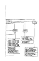
クライアント能力データを直接転送する代わりに、ディレクトリを介してこれを実行してもよい。この方法は、出願中の欧州特許出願第97309810.6号(1997年12月4日出願)(代理人参照番号A25527)に記載されており、これは参考文献として本明細書に取り上げる。図7はデータ交換がディレクトリプラットフォーム7によって取り次がれる実施形態を示している。ディレクトリプラットフォーム7はリンク8によってネットワークへ接続され、リンク8はネットワークとディレクトリプラットフォーム7との間でIPデータを転送する。ネットワークの他の構成要素には、図1に関係して既に記載したものがある。
【0024】
使用の際に、ユーザ端末2、3の両方における顧客はディレクトリサーバに登録し、この例ではディレクトリサーバはディレクトリプラットフォーム7上を走行する。次に後でさらに詳しく記載するように、ユーザ端末2における顧客はユーザ端末3に登録された顧客と接触することを望むとき、ディレクトリサーバへ要求が送られる。この要求は、ディレクトリプラットフォーム7のIPアドレスへ送られる。この要求には、被呼顧客を識別する顧客名のようなデータを含む。ディレクトリサーバはこのデータを使用して、顧客がディレクトリサーバに登録したときに生成された対応するユーザプロフィールを選択する。選択されたユーザプロフィールから、ディレクトリサーバは発呼顧客に被呼顧客のネットワークアドレスおよび呼制御能力を戻す。この情報を使用して、発呼顧客は他の顧客への呼を設定する。例えばこの例における発呼顧客は、ATM呼制御プロトコル(Q.2931)を使用してATMアドレス(ATM2)への接続を設定することを選択することができる。
【0025】
図10および11は、この実施形態にしたがってローカルクライアントがその呼制御能力をディレクトリに登録し、次に遠隔のクライアントが呼制御能力データを読取るとき、ローカルクライアント、ディレクトリプラットフォーム(または“サーバ”)7、および遠隔のクライアントとの間のメッセージ流を示す。
【図面の簡単な説明】
【図1】 本発明を実現する第1のネットワークの模式図。
【図2】 能力データの交換を示す図。
【図3】 本発明を実現するシステムのプロトコルスタックを示す図(図3aおよび3b)。
【図4】 本発明を実現するシステムにおけるメッセージフローシーケンスを示す図(図4aおよび4b)。
【図5】 本発明を構成するソフトウエアオブジェクトの一部を示すダイヤグラム。
【図6】 図5に続く本発明を構成するソフトウエアオブジェクトの一部を示すダイヤグラム。
【図7】 図6に続く本発明を構成するソフトウエアオブジェクトを示すダイヤグラム。
【図8】 本発明を構成するソフトウエアオブジェクトを示すダイヤグラム。
【図9】 本発明を実現する第1のネットワークの変形例を示す模式図。
【図10】 第2の実施形態にしたがうネットワークにおけるメッセージ流の一部を示す図。
【図11】 図10に続く第2の実施形態にしたがうネットワークにおけるメッセージ流の一部を示す図。[0001]
The present invention relates to communication systems, and more particularly to heterogeneous systems in which customers employ a number of different call control mechanisms and different address types.
[0002]
In a conventional homogeneous communication network, such as a prior art public switched telephone network (PSTN), the customer has only one type of address (in this example, a telephone number) and one uniform incorporated into the network. Call control mechanisms. The call control mechanism is used to set up, terminate and recognize, for example, when the called party is busy. Increasingly, however, customers have access to different network technologies, each with its own address type. For example, a customer may have a conventional IP (Internet Protocol) address, a multicast IP address, and a URL (Uniform Resource Locator) in addition to a telephone number. In general, each of these different address types is associated with it and a respective call control protocol (still using the term “call control” to indicate a means of establishing and terminating connections between different parties generally). ing. For example, audio and visual communication between parties using conventional IP addresses is generally H.264. While using the H.323 protocol, communication between broadband ATM addresses uses a different protocol, namely B-ISDN (Broadband Integrated Services Digital Network). In practice, the call control protocol used for a particular communication session tends to be determined and determined by the party initiating the session. When other parties later join the session, they are limited to using the addressing and call control capabilities determined by the first party.
[0003]
SUMMARY OF THE INVENTION According to a first aspect of the present invention, a method for operating a communication system comprising:
(A) exchanging call control capability data between the communication terminals for identifying one selected from a plurality of different call control protocols and different network addresses for each of the communication terminals with which the call control capability data is exchanged;
(B) setting up a call between the communication terminals using a call control protocol or network address identified in the call control capability data.
[0004]
The present invention allows peer terminals to be fully utilized by exchanging data identifying call control and address types by fully utilizing the capabilities of the terminals in a heterogeneous communication system. By using this mechanism, this solution eliminates the full potential of heterogeneous communication systems because it eliminates the need to adopt a “lowest common denominator” for addressing and call control types. can do. This facilitates the use of these advanced call control and addressing mechanisms that are more flexible, even when the advanced call control and addressing mechanisms are initially used only by a few terminals in the communication system. To help.
[0005]
Preferably, the step of exchanging call control capability data is performed prior to initiating call setup.
[0006]
Data exchange may be integrated into the call setup process to form the first part of the call setup process. However, for maximum flexibility, it is preferable to exchange data independently prior to call setup. Thus, the user may choose not to proceed with the call setup process depending on the capabilities of the or each other terminal.
[0007]
Preferably, the first terminal initiates the exchange of call control capability data by sending call control capability data for the first terminal to the second terminal, and the second terminal is a call for the second terminal. Returns an acknowledgment of the request containing control capability data.
[0008]
It has been found that it is particularly effective to exchange data with each other using simple requests / responses.
[0009]
The method preferably includes continuously monitoring the communication port at the communication terminal and performing an exchange of call control capability data whenever a request is received at the port. Preferably the monitoring phase continues after the call is set up.
[0010]
The preferred arrangement further improves the flexibility of the communication system by allowing capability data exchange to be performed at any time. The preferred configuration further allows the system to respond to the arrival of a new member with new communication capabilities in a multi-party communication session, or to respond to a change in one of the parties' capabilities during an ongoing session. Yes.
[0011]
According to a second aspect of the present invention, a communication terminal comprising:
(A) for each terminal, means for exchanging call control capability data identifying one or more selected from a plurality of different call control protocols and different network addresses with other communication terminals;
(B) setting up a call between the communication terminal and another communication terminal using a call control protocol or network address type identified in the call control capability data received from the other communication terminal; And a communication terminal including the means.
[0012]
The present invention further includes a communication system including a communication terminal according to the second aspect of the present invention.
[0013]
The method and system embodying the present invention will now be described in further detail by way of example with reference to the accompanying drawings.
[0014]
DETAILED DESCRIPTION OF THE INVENTION A
[0015]
As shown in FIG. 2, the exchange mechanism operates when a TRANSFER. Request primitive is issued by the user of the output client. The TRANSFER. Request from the first client includes a set of client capabilities for the corresponding terminal. This set of client capabilities represents all call control technologies and addresses supported by the terminal. The incoming client user is informed of the client capability data exchange request by the TRANSFER. The incoming client user initiates the transfer of capabilities using the TRANSFER.request primitive. The ability of the incoming terminal, ie the terminal that receives the incoming client's capability exchange request, is sent back to the sending terminal using the client capability set acknowledgment message. The user of the sending client is informed that the capability data exchange was performed by the TRANSFER.confirm primitive.
[0016]
The client capability set data in the above message identifies any of a number of predetermined address types, and a call control type is supported. Examples of different address types that can be supported are email, URL (Uniform Resource Locator), IP Multi-Case, IP Unicast, E.C. 164, including AESA. Examples of different call control types are H.264. 225.0, SDP, B-ISDN 2917, B-ISDN ATM-F UNI, N-ISDN Q.I. 931, PSTN BTNR 315.
[0017]
Table 1 below contains a complete list of address and call control types supported by one configuration of the present invention. As shown in the table, different integer codes are used to identify each different call control and address type.
[0018]
[Table 1]
As shown in Table 1, the capabilities communicated through the capability exchange mechanism may include a URL (Uniform Resource Locator). The URL is accessed by the terminal that initiated the transfer of the set of capabilities and can read details of other capabilities other than the capabilities given in Table 1. In this way, the capability exchange protocol can be extended to include new call protocols. The URL directs the terminal to a resource such as a Java applet, which can be downloaded by the terminal to facilitate communication with the terminal that prepared the URL. For example, a URL may relate to an HTTP page that includes a Java applet that displays a “call me” button. Therefore, when this button is clicked, a call is made from the terminal having the URL to another terminal.
[0020]
Figures 3a and 3b show the software architecture of a system implementing the present invention. Each communication terminal executes a communication program including a communication graphical user interface (GUI 31) on the communication application 32. The communication application 32 is supported by a number of resources under this including the capability exchange module (CE), where the “listener module L” is a predetermined socket defined by the IP address of the communication terminal along with a 16-bit port number Is continuously monitored. The CE and listener modules are based on the Session Invitation Protocol (SIP) shown in FIG. It may be present with other modules such as 323 modules. Capability set messages are sent between the UDP / TCP / IP layer and the capability exchange (CE) module. The listener module communicates between the transfer primitive and the CE module. In this preferred configuration, UDP (unreliable datagram protocol) is used rather than TCP (Transport Control Protocol) for sending capability set data across the network. This avoids the overhead associated with setting up a TCP data stream. However, this solution then addresses the possibility of losing a packet by requiring the packet to be sent again if it has not been acknowledged after a predetermined period of time. FIG. 3b shows the message flow across different APIs (application programmer interfaces) when capability data is exchanged between two terminals. The transfer primitive shown in FIG. 2 corresponds to an API between the application layer (configured in this example using Java language) and a lower layer of the protocol stack.
[0021]
Figures 4a and 4b show in more detail the sequence of message flows between terminals A and B in different configurations of the invention. In the sequence of FIG. 4a, the capability data exchange occurs before the session is established. Immediately after the exchange of capability data, for example The call is set up using a message sequence defined for an ISDN protocol such as 320, but the capability data in this case indicates that both parties had this call control capability. In the second example shown in FIG. 4b, after the capability data exchange, before setting up the call, for example A session is set up using the H.323 call control protocol, i.e., Session Invitation Protocol (SIP).
[0022]
5, 6, 7 and 8 are diagrams showing the definition of software objects constituting the above-described embodiment using a relational ROSE (Relational Object-oriented Software Engineering) format. In the illustrated configuration, it can be compiled using ROSE software tools sold by Relational Software Corp. (Santa Clara, California) to generate, for example, C ++ code to form the basis of the configuration of the present invention. it can. As shown in FIG. 6, client objects as shown on each terminal include clientcapabilityset and clientcapabilityreturn methods, which are inherited by the client capability objects. Instead, the characteristics of the client capability object are inherited by the address and call control objects as shown in FIG.
[0023]
Instead of transferring client capability data directly, this may be done via a directory. This method is described in pending European Patent Application No. 97309810.6 (filed December 4, 1997) (Attorney Reference No. A25527), which is hereby incorporated by reference. FIG. 7 shows an embodiment in which data exchange is relayed by the
[0024]
In use, customers at both
[0025]
FIGS. 10 and 11 show that when a local client registers its call control capability in a directory according to this embodiment and then the remote client reads the call control capability data, the local client, directory platform (or “server”) 7 , And the flow of messages between remote clients.
[Brief description of the drawings]
FIG. 1 is a schematic diagram of a first network for realizing the present invention.
FIG. 2 is a diagram showing exchange of capability data.
FIG. 3 shows a protocol stack of a system implementing the present invention (FIGS. 3a and 3b).
4 shows a message flow sequence in a system for realizing the present invention (FIGS. 4a and 4b).
FIG. 5 is a diagram showing a part of software objects constituting the present invention.
FIG. 6 is a diagram showing a part of software objects constituting the present invention following FIG. 5;
FIG. 7 is a diagram showing software objects constituting the present invention following FIG. 6;
FIG. 8 is a diagram showing software objects constituting the present invention.
FIG. 9 is a schematic diagram showing a modified example of the first network for realizing the present invention.
FIG. 10 shows a part of a message flow in a network according to the second embodiment.
FIG. 11 is a diagram showing a part of a message flow in the network according to the second embodiment following FIG. 10;
Claims (9)
(b)前記呼制御能力データにおいて識別される呼制御プロトコルまたはネットワークアドレスを使用して、前記通信端末間の呼を設定するステップとを含み、
呼制御能力データを交換するステップが、呼の設定を開始する前に実行される、通信システムを動作する方法。 A step of exchanging call control capability data between (a) the communication terminal, the call control capability data, for each respective terminal, identifying a network address different from the plurality of different call control protocols;
(B) using said call control protocol or network address identified in the call control capability data, and a step of setting a call between the communication terminals,
A method of operating a communication system, wherein the step of exchanging call control capability data is performed prior to initiating call setup.
(a)第1の端末において、第2の端末に関する呼制御能力データを受信するステップであり、呼制御能力データが、第2の端末について、複数の異なる呼制御プロトコルおよび異なるネットワークアドレスを識別するステップと;
(b)第1の通信装置から受信した呼制御能力データにおいて特定されている異なる呼制御プロトコルおよびネットワークアドレスから選択されたものを使用して、第1の通信端末から第2の通信端末への呼を設定するステップとを含み、
呼制御能力データを受信するステップが、呼の設定を開始する前に実行される方法。A method for setting up a call between a first communication terminal and a second communication terminal comprising:
(A) In the first terminal, a step of receiving a call control capability data for the second terminal, the call control capability data for the second terminal, identifying a plurality of different call control protocols and different network addresses Steps and;
(B) From the first communication terminal to the second communication terminal using a selection from a different call control protocol and network address specified in the call control capability data received from the first communication device. and a step of setting a call,
A method wherein the step of receiving call control capability data is performed prior to initiating call setup.
(a)呼制御能力データを他方の通信端末と交換する手段であって、呼制御能力データが、それぞれの端末について、複数の異なる呼制御プロトコルおよび異なるネットワークアドレスから選択された1つ以上のものを識別する手段と;
(b)前記他方の通信端末から受信した呼制御能力データにおいて識別される呼制御プロトコルまたはネットワークアドレスタイプを使用して、前記通信端末と他方の通信端末との間の呼を設定する手段とを含み、
端末が、呼の設定を開始する前に、呼制御能力データを交換するように動作することができる通信端末。Communication terminal:
(A) Means for exchanging call control capability data with another communication terminal, wherein the call control capability data is one or more selected from a plurality of different call control protocols and different network addresses for each terminal. Means for identifying;
(B) means for setting up a call between the communication terminal and the other communication terminal using a call control protocol or network address type identified in the call control capability data received from the other communication terminal; Including
A communication terminal capable of operating to exchange call control capability data before the terminal initiates call setup.
(a)呼制御能力データを他方の通信端末と交換する手段であって、呼制御能力データが、それぞれの端末について、複数の異なる呼制御プロトコルおよび異なるネットワークアドレスから選択された1つ以上のものを識別する手段と;
(b)前記他方の通信端末から受信した呼制御能力データにおいて識別される呼制御プロトコルまたはネットワークアドレスタイプを使用して、前記通信端末と他方の通信端末との間の呼を設定する手段とを含み、
端末の各々が、呼の設定を開始する前に、呼制御能力データを交換するように動作することができる通信ネットワーク。A communication network including a plurality of communication terminals, wherein different ones of the plurality of communication terminals support different respective call control protocols, each of the communication terminals:
(A) Means for exchanging call control capability data with another communication terminal, wherein the call control capability data is one or more selected from a plurality of different call control protocols and different network addresses for each terminal. Means for identifying;
(B) means for setting up a call between the communication terminal and the other communication terminal using a call control protocol or network address type identified in the call control capability data received from the other communication terminal; Including
A communication network in which each of the terminals can operate to exchange call control capability data before initiating call setup.
Applications Claiming Priority (5)
| Application Number | Priority Date | Filing Date | Title |
|---|---|---|---|
| EP97309810 | 1997-12-04 | ||
| EP97309810.6 | 1997-12-04 | ||
| EP98302452 | 1998-03-30 | ||
| EP98302452.2 | 1998-03-30 | ||
| PCT/GB1998/003501 WO1999029135A1 (en) | 1997-12-04 | 1998-11-24 | Communications network |
Publications (3)
| Publication Number | Publication Date |
|---|---|
| JP2002514018A JP2002514018A (en) | 2002-05-14 |
| JP2002514018A5 JP2002514018A5 (en) | 2006-03-23 |
| JP4270749B2 true JP4270749B2 (en) | 2009-06-03 |
Family
ID=26147726
Family Applications (1)
| Application Number | Title | Priority Date | Filing Date |
|---|---|---|---|
| JP2000523826A Expired - Lifetime JP4270749B2 (en) | 1997-12-04 | 1998-11-24 | Communication network |
Country Status (9)
| Country | Link |
|---|---|
| US (1) | US7142510B1 (en) |
| EP (1) | EP1036481B1 (en) |
| JP (1) | JP4270749B2 (en) |
| CN (1) | CN1222193C (en) |
| AU (1) | AU1249399A (en) |
| CA (1) | CA2313042C (en) |
| DE (1) | DE69834205T2 (en) |
| ES (1) | ES2259820T3 (en) |
| WO (1) | WO1999029135A1 (en) |
Families Citing this family (11)
| Publication number | Priority date | Publication date | Assignee | Title |
|---|---|---|---|---|
| GB2350257A (en) * | 1999-05-17 | 2000-11-22 | Ericsson Telefon Ab L M | Capability negotiation in a telecommunications network |
| EP1179264B1 (en) | 1999-05-17 | 2008-12-17 | Telefonaktiebolaget LM Ericsson (publ) | Capability negotiation in a telecommunications network |
| CN100375481C (en) * | 2002-10-09 | 2008-03-12 | 中兴通讯股份有限公司 | Method and system for realizing inter communication of telecommunication business between isomerized networks |
| US7480287B2 (en) | 2002-11-19 | 2009-01-20 | Murata Kikai Kabushiki Kaisha | Communication terminal device, communication method and electronic mail server |
| JP4013153B2 (en) * | 2004-04-20 | 2007-11-28 | 村田機械株式会社 | Communication apparatus and program |
| JP2006186773A (en) * | 2004-12-28 | 2006-07-13 | Kddi Corp | Unit and method for protocol generation and program therefor |
| ES2422192T3 (en) | 2005-02-08 | 2013-09-09 | Psygnificant Services Ltd | Call notification controlled by a call origin system |
| US9401934B2 (en) * | 2005-06-22 | 2016-07-26 | Microsoft Technology Licensing, Llc | Establishing sessions with defined quality of service |
| US7839870B2 (en) * | 2005-11-23 | 2010-11-23 | Comcast Cable Holdings, Llc | Device-to-device communication among customer premise equipment devices |
| EA201000597A1 (en) * | 2007-10-16 | 2010-10-29 | Псайгнивикант Сервисес Лимитед | SYSTEM AND METHOD OF COMMUNICATION |
| CN109861876A (en) * | 2018-12-29 | 2019-06-07 | 深圳市路畅科技股份有限公司 | A kind of method and relevant apparatus of Three-Way Calling test |
Family Cites Families (7)
| Publication number | Priority date | Publication date | Assignee | Title |
|---|---|---|---|---|
| JPH02220531A (en) * | 1989-02-22 | 1990-09-03 | Toshiba Corp | Call connection control system and flow monitor system |
| JPH07118717B2 (en) * | 1993-01-05 | 1995-12-18 | 日本電気株式会社 | Multi-protocol packet network configuration method |
| US5561666A (en) * | 1995-03-06 | 1996-10-01 | International Business Machines Corporation | Apparatus and method for determining operational mode for a station entering a network |
| US6085238A (en) * | 1996-04-23 | 2000-07-04 | Matsushita Electric Works, Ltd. | Virtual LAN system |
| KR100259409B1 (en) * | 1996-09-23 | 2000-06-15 | 포만 제프리 엘 | Control of a telephone switching system over a digital information network |
| EP0851706A1 (en) * | 1996-12-24 | 1998-07-01 | International Business Machines Corporation | Flow control for very bursty connections in high speed cell switching networks |
| US6125123A (en) * | 1997-03-14 | 2000-09-26 | Fujitsu Limited | Signaling method, switching system, storage medium and network |
-
1998
- 1998-11-24 ES ES98955764T patent/ES2259820T3/en not_active Expired - Lifetime
- 1998-11-24 DE DE69834205T patent/DE69834205T2/en not_active Expired - Lifetime
- 1998-11-24 US US09/530,785 patent/US7142510B1/en not_active Expired - Lifetime
- 1998-11-24 CN CN98811866.1A patent/CN1222193C/en not_active Expired - Lifetime
- 1998-11-24 EP EP98955764A patent/EP1036481B1/en not_active Expired - Lifetime
- 1998-11-24 WO PCT/GB1998/003501 patent/WO1999029135A1/en active IP Right Grant
- 1998-11-24 JP JP2000523826A patent/JP4270749B2/en not_active Expired - Lifetime
- 1998-11-24 AU AU12493/99A patent/AU1249399A/en not_active Abandoned
- 1998-11-24 CA CA002313042A patent/CA2313042C/en not_active Expired - Fee Related
Also Published As
| Publication number | Publication date |
|---|---|
| AU1249399A (en) | 1999-06-16 |
| EP1036481A1 (en) | 2000-09-20 |
| DE69834205T2 (en) | 2007-03-08 |
| CN1281626A (en) | 2001-01-24 |
| US7142510B1 (en) | 2006-11-28 |
| CN1222193C (en) | 2005-10-05 |
| JP2002514018A (en) | 2002-05-14 |
| DE69834205D1 (en) | 2006-05-24 |
| WO1999029135A1 (en) | 1999-06-10 |
| CA2313042C (en) | 2007-02-13 |
| ES2259820T3 (en) | 2006-10-16 |
| CA2313042A1 (en) | 1999-06-10 |
| EP1036481B1 (en) | 2006-04-12 |
Similar Documents
| Publication | Publication Date | Title |
|---|---|---|
| KR100433577B1 (en) | Method and apparatus for synchronizing information browsing among multiple systems | |
| CN100512165C (en) | Method, device and system for facilitating peer-to-peer application communication | |
| US7266591B1 (en) | Providing content delivery during a call hold condition | |
| US6512818B1 (en) | Method and system for releasing a voice response unit from a protocol session | |
| US9008294B2 (en) | Providing calling party information in a request to establish a call session | |
| US7458084B2 (en) | Methods and systems for converged service creation and execution environment applications | |
| AU772765B2 (en) | SIP-based feature control | |
| US8233596B2 (en) | Providing subscriber information in voice over IP (VoIP) system | |
| JP2001358778A (en) | Communication system, communication gateway and communicating method | |
| WO1998041002A1 (en) | Method and apparatus for providing customized voice call processing | |
| AU2006280344A1 (en) | Associating a telephone call with a dialog based on a computer protocol such as SIP | |
| EP1287656B1 (en) | Launching software routines in response to messages relating to communications sessions | |
| JP4270749B2 (en) | Communication network | |
| EP1608127A1 (en) | VoIP network, media Proxy Server, and method of providing additional services used in them | |
| US20080137647A1 (en) | VoIP terminal and method for providing multi-call service |
Legal Events
| Date | Code | Title | Description |
|---|---|---|---|
| A521 | Request for written amendment filed |
Free format text: JAPANESE INTERMEDIATE CODE: A523 Effective date: 20051117 |
|
| A621 | Written request for application examination |
Free format text: JAPANESE INTERMEDIATE CODE: A621 Effective date: 20051117 |
|
| A977 | Report on retrieval |
Free format text: JAPANESE INTERMEDIATE CODE: A971007 Effective date: 20080702 |
|
| A131 | Notification of reasons for refusal |
Free format text: JAPANESE INTERMEDIATE CODE: A131 Effective date: 20080708 |
|
| A601 | Written request for extension of time |
Free format text: JAPANESE INTERMEDIATE CODE: A601 Effective date: 20080917 |
|
| A602 | Written permission of extension of time |
Free format text: JAPANESE INTERMEDIATE CODE: A602 Effective date: 20080925 |
|
| A521 | Request for written amendment filed |
Free format text: JAPANESE INTERMEDIATE CODE: A523 Effective date: 20090108 |
|
| TRDD | Decision of grant or rejection written | ||
| A01 | Written decision to grant a patent or to grant a registration (utility model) |
Free format text: JAPANESE INTERMEDIATE CODE: A01 Effective date: 20090127 |
|
| A01 | Written decision to grant a patent or to grant a registration (utility model) |
Free format text: JAPANESE INTERMEDIATE CODE: A01 |
|
| A61 | First payment of annual fees (during grant procedure) |
Free format text: JAPANESE INTERMEDIATE CODE: A61 Effective date: 20090224 |
|
| FPAY | Renewal fee payment (event date is renewal date of database) |
Free format text: PAYMENT UNTIL: 20120306 Year of fee payment: 3 |
|
| R150 | Certificate of patent or registration of utility model |
Free format text: JAPANESE INTERMEDIATE CODE: R150 |
|
| FPAY | Renewal fee payment (event date is renewal date of database) |
Free format text: PAYMENT UNTIL: 20120306 Year of fee payment: 3 |
|
| FPAY | Renewal fee payment (event date is renewal date of database) |
Free format text: PAYMENT UNTIL: 20130306 Year of fee payment: 4 |
|
| FPAY | Renewal fee payment (event date is renewal date of database) |
Free format text: PAYMENT UNTIL: 20130306 Year of fee payment: 4 |
|
| FPAY | Renewal fee payment (event date is renewal date of database) |
Free format text: PAYMENT UNTIL: 20140306 Year of fee payment: 5 |
|
| R250 | Receipt of annual fees |
Free format text: JAPANESE INTERMEDIATE CODE: R250 |
|
| R250 | Receipt of annual fees |
Free format text: JAPANESE INTERMEDIATE CODE: R250 |
|
| R250 | Receipt of annual fees |
Free format text: JAPANESE INTERMEDIATE CODE: R250 |
|
| R250 | Receipt of annual fees |
Free format text: JAPANESE INTERMEDIATE CODE: R250 |
|
| R250 | Receipt of annual fees |
Free format text: JAPANESE INTERMEDIATE CODE: R250 |
|
| EXPY | Cancellation because of completion of term |