JP4269552B2 - Game media lifting device - Google Patents
Game media lifting device Download PDFInfo
- Publication number
- JP4269552B2 JP4269552B2 JP2001359362A JP2001359362A JP4269552B2 JP 4269552 B2 JP4269552 B2 JP 4269552B2 JP 2001359362 A JP2001359362 A JP 2001359362A JP 2001359362 A JP2001359362 A JP 2001359362A JP 4269552 B2 JP4269552 B2 JP 4269552B2
- Authority
- JP
- Japan
- Prior art keywords
- conveyor belt
- belt
- game medium
- color
- lifting device
- Prior art date
- Legal status (The legal status is an assumption and is not a legal conclusion. Google has not performed a legal analysis and makes no representation as to the accuracy of the status listed.)
- Expired - Fee Related
Links
- 238000001514 detection method Methods 0.000 claims description 22
- 239000010410 layer Substances 0.000 claims description 19
- 239000003086 colorant Substances 0.000 claims description 10
- 239000002344 surface layer Substances 0.000 claims description 6
- 238000005498 polishing Methods 0.000 description 21
- 239000003550 marker Substances 0.000 description 11
- 239000002184 metal Substances 0.000 description 11
- 229910052751 metal Inorganic materials 0.000 description 11
- 238000000034 method Methods 0.000 description 6
- XEEYBQQBJWHFJM-UHFFFAOYSA-N Iron Chemical compound [Fe] XEEYBQQBJWHFJM-UHFFFAOYSA-N 0.000 description 2
- 230000005540 biological transmission Effects 0.000 description 2
- 238000010586 diagram Methods 0.000 description 2
- 239000000428 dust Substances 0.000 description 2
- 238000012544 monitoring process Methods 0.000 description 2
- 238000010079 rubber tapping Methods 0.000 description 2
- 235000019504 cigarettes Nutrition 0.000 description 1
- 238000011109 contamination Methods 0.000 description 1
- 230000000694 effects Effects 0.000 description 1
- 230000003203 everyday effect Effects 0.000 description 1
- 230000010354 integration Effects 0.000 description 1
- 229910052742 iron Inorganic materials 0.000 description 1
- 230000000737 periodic effect Effects 0.000 description 1
- 239000011347 resin Substances 0.000 description 1
- 229920005989 resin Polymers 0.000 description 1
- 238000000926 separation method Methods 0.000 description 1
- 238000004904 shortening Methods 0.000 description 1
Images


Landscapes
- Pinball Game Machines (AREA)
Description
【0001】
【発明の属する技術分野】
本発明は、パチンコ機やスロット機などの遊技機に使用される遊技球やコインなどの遊技媒体を揚送する遊技媒体揚送装置に係わり、とくに、搬送ベルトの交換を的確な時期に行えるようにした装置に関するものである。
【0002】
【従来の技術】
例えばパチンコ遊技場では、複数のパチンコ機を列設してパチンコ島を構成し、各パチンコ機から排出された遊技球はパチンコ島の下部中央部に集まるようになっている。この集まった遊技球をパチンコ島の上部へ揚送して、再度各パチンコ機へ分配するための遊技媒体揚送装置が設置されている。
【0003】
この遊技媒体揚送装置は、立設された揚送筒体の上下に設けられたローラに搬送ベルトを巻回し、該搬送ベルトに対向して上下に張設した研磨ベルトを備え、遊技球を搬送ベルトと研磨ベルトとの間に挟み込んで揚送するように構成されている。
【0004】
遊技媒体揚送装置の下部には搬送ベルトを循環駆動させる駆動手段と、搬送ベルトに張力を与えるベルト張力機構が設けられ、駆動手段で搬送ベルトを駆動すると、遊技球は研磨ベルトと搬送ベルトとの間で摩擦を受けながら揚送されるが、その間に遊技球に付着した煙草のヤニやほこりを研磨ベルトに付着させることによって除去している。
【0005】
【発明が解決しようとする課題】
上記のように研磨ベルトは遊技球の汚染を除去しているので、汚れが早く定期的(例えば毎日)に交換されている。
一方、搬送ベルトは高価でもあり、長期間使用されるため、遊技球と接触によって搬送ベルトが摩耗することや、ベルト張力機構によって搬送ベルトが伸長することで、厚さが薄くなって研磨ベルトとの間隔が広がってしまい、遊技球を確実に挟持することができなくなり搬送能力を低下させることがある。
【0006】
遊技場ではこのような状態が発生しないように研磨ベルトとの間隔を調整したり搬送ベルトを交換している。調整や交換する時期は、搬送ベルトの状態を観察して経験に基づいて判断している。
しかし、この判断は熟練した判断者でもかなり難しく、また、判断者によって区々となるので、的確とはいえない。このため、一般には期間を定めて定期的に調整や交換を行っており、交換作業は取付位置の調整などが面倒なので専門業者に依頼している。
【0007】
しかしながら、搬送ベルトが調整作業や交換作業が必要な厚さの薄い状態になるのは各遊技場における温度や湿度などの環境や、遊技媒体揚送装置毎に研磨ベルトとの間隔が異なることもあって、搬送ベルト毎に異なるものである。したがって、定期的な調整作業や交換作業では時期が早すぎたり、遅すぎたりするという問題がある。
【0008】
そこで、本発明は、研磨部材との間隔調整や搬送ベルトの交換を行ったほうがよい適切な時期を判断することができる遊技媒体揚送装置を提供することを目的としている。
【0009】
【課題を解決するための手段および効果】
上記目的を達するためになされた請求項1記載の発明は、揚送筒体の上下に設けたローラに搬送ベルトを巻回し、該搬送ベルトに対向して研磨部材を設け、遊技媒体を該搬送ベルトと該研磨部材との間に挟み込んで揚送する遊技媒体揚送装置において、前記搬送ベルトは、層ごとに色彩が異なる複数層を有する多層のベルトであるとともに、前記搬送ベルトの表層の色を検出するカラーセンサを、前記搬送ベルトの幅方向に複数備え、前記複数のカラーセンサの検出パターンと、前記搬送ベルトの状態とを対応させて記憶する記憶手段を備え、前記複数のカラーセンサの検出パターンに対応する前記搬送ベルトの状態を表示する表示手段を備えることを特徴とする。
請求項2記載の発明は、揚送筒体の上下に設けたローラに搬送ベルトを巻回し、該搬送ベルトに対向して研磨部材を設け、遊技媒体を該搬送ベルトと該研磨部材との間に挟み込んで揚送する遊技媒体揚送装置において、前記搬送ベルトは、層ごとに色彩が異なる3層以上の層を有する多層のベルトであるとともに、前記搬送ベルトの幅方向の略全体について、前記搬送ベルトの表層の色を検出するカラーセンサを備えることを特徴とする遊技媒体揚送装置を要旨とする。
請求項3記載の発明は、揚送筒体の上下に設けたローラに搬送ベルトを巻回し、該搬送ベルトに対向して研磨部材を設け、遊技媒体を該搬送ベルトと該研磨部材との間に挟み込んで揚送する遊技媒体揚送装置において、前記搬送ベルトは、層ごとに色彩が異なる3層以上の層を有する多層のベルトであるとともに、前記搬送ベルトの表層の色を検出するカラーセンサを、前記搬送ベルトの幅方向に複数備えることを特徴とする遊技媒体揚送装置を要旨とする。
【0010】
本発明では、例えば搬送ベルトを層状にして、摩耗したときに表面に表れる層に目印となる色彩を施してもよい。この色彩は搬送ベルト全体に施してもよいし、部分的でもよい。このように構成された本発明では、搬送ベルトが所定摩耗量まで摩耗すると所定摩耗量まで摩耗したことを容易に判断することができる。したがって、例えば、所定摩耗量を搬送ベルトの交換時期に設定すれば、搬送ベルトの状態を観察して交換するかどうかを判断するといった熟練の判断者でも煩雑であった作業を行わなくても、各遊技媒体揚送装置毎にその搬送ベルトの交換を行ったほうがよい適切な時期か否かを容易に判断でき、この判断に基づいて適切な時期に搬送ベルトを交換することが可能となる。また、所定摩耗量を遊技媒体揚送装置の調整時期に設定すれば、調整を行った方がよい適切な時期か否かを容易に判断でき、この判断に基づいて適切な時期に遊技媒体揚送装置の間隔調整をすることが可能となる。その結果、遊技媒体揚送装置を良好な状態に維持することが可能となる。
【0011】
【0012】
【0013】
【0014】
【0015】
【0016】
【0017】
【0018】
【0019】
【0020】
【0021】
【0022】
【0023】
【0024】
【0025】
【0026】
【0027】
【0028】
【0029】
【0030】
【0031】
【0032】
本発明では、搬送ベルトを色彩の異なる多層のベルトとすることで、剥離が発生したら表面の一部に異なる色彩が現れる。そのため、本発明では、搬送ベルトが剥離していることを容易に判断することができる。したがって、釘などの異物混入により剥離が発生した場合や、搬送ベルトが切断する前に剥離が発生した場合などの搬送ベルトの早急な交換が必要な場合に、搬送ベルトの交換を促すことができ、剥離の発見が遅れて遊技媒体の循環供給が損なわれることを防止できる。さらには、搬送ベルトの剥離により遊技媒体揚送装置の部品が破損してしまうといった二次的被害も防止できる。
【0033】
【0034】
【0035】
【0036】
【0037】
【0038】
【0039】
【0040】
【0041】
【0042】
【0043】
【0044】
【発明の実施の形態】
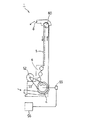
次に、本発明の実施の形態を図面と共に説明する。図1は、本発明が適用された遊技球揚送装置1の構成を表す斜視図である。なお、本実施の形態の遊技媒体揚送装置としての遊技球揚送装置1は、図示しない遊技機島としてのパチンコ島の内部に設けられ、そのパチンコ島の各パチンコ機から排出されて貯留タンクに貯留された遊技媒体としての遊技球を、そのパチンコ島上方の上部タンクに揚送するものである。
【0045】
図1に示すように、遊技球揚送装置1は、支持台2の上部に揚送筒体3が立設され、揚送筒体3の下部には下部ローラ4を、上部には図示しない上部ローラが設けられ、これに無端の搬送ベルト5が掛け渡されている。また、遊技球揚送装置1には、搬送ベルト5を循環駆動させる駆動手段としての図示しない駆動モータが取り付けられている。
【0046】
そして、搬送ベルト5の下降側に搬送ベルト5に張力を付与するためのベルト張力機構6が設けられている。
一方、前記した揚送筒体3の背面側には、側方へ開閉可能なガイドレール7が係止金具9と支持金具10(図2(b)参照)によって取り付けられ、図示しない研磨部材としての研磨ベルトの上方側を固定するベルト固定金具11aと下方側を固定する固定金具11bが取り付けられている。
【0047】
また、揚送筒体3の下部には、貯留タンクから送られた遊技球を複数列に整列させる導入樋12が設けられ、揚送筒体3の上部には、遊技球の排出口8が形成されている。
このように構成されているので、導入樋12から流入された遊技球は、搬送ベルト5と研磨ベルトとの間に挟み込んで揚送され、その揚送される過程で研磨ベルトとの摩擦力によって遊技球に付着した汚れが拭き取られ、排出口8から排出される。
【0048】
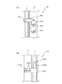
ここで、ガイドレール7を支持する係止金具9は、図2(a)に示すように、揚送筒体3に金具9aが上下2本のボルト9d,9eで固定され、これに係止レバー9bが回動可能に取り付けられている。係止レバー9bの先端部はガイドレール7に突設したピン9cに係止している。また、ボルト9eを取り付ける金具9aに設けられた穴は横方向の長穴になっているため、金具9aがボルト9dを中心として回転移動可能となっており、ボルト9dと係止レバー9bの先端部との水平方向の距離を変えることができる。つまり、揚送筒体3とガイドレール7との隙間の間隔を変更することができるようになっている。
【0049】
また、ガイドレール7の他方の側面に設けられた支持金具10は、図2(b)に示すように、ガイドレール7に取り付けた金具10dが下部のスライド板10aに対してピン10eを軸として水平方向に回動可能に取り付けられている。
スライド板10aは揚送筒体3に2本のボルト10bで固定されており、ボルト10bを取り付ける穴はいずれも水平方向の長穴になっているため、長穴の分だけ金具10dが移動可能となっており、ボルト10bと金具10dとの水平方向の距離を変えることができる。つまり、揚送筒体3とガイドレール7との隙間の間隔を変更できるようになっている。なお、10cはスライド板10aに形成されたピン10eの受部である。
【0050】
搬送ベルト5と研磨ベルトとの間の隙間の調整は、揚送筒体3とガイドレール7との間の隙間を調整することによって行われる。
この作業について詳述すると、支持金具10の2本のボルト10bおよび係止金具9のボルト9d,9eを緩め、支持金具10側の揚送筒体3とガイドレール7との隙間に所望の厚みゲージを差し込んでスライド板10aの受部10dをハンマーで軽く叩きながらゲージ厚に一致するように調節した後、ボルト10bを締めて固定する。そして、係止金具9側の揚送筒体3とガイドレール7との隙間にも同じ厚みゲージを差し込んで金具9aの上部をハンマーで軽く叩きながらゲージ厚に一致するように調節した後、ボルト9d,9eを締めて固定している。
【0051】
このような作業により、搬送ベルト5と研磨ベルトとの隙間間隔が調整されるようになっている。
次に、ベルト張力機構6は図3に示すように、搬送ベルト5が交互に当接する固定ローラ14,テンションローラ15および固定ローラ18からなり、固定ローラ14および固定ローラ18のローラ軸は所定の位置に固定されている。
【0052】
そして、テンションローラ15は固定ローラ14と固定ローラ18の中間に位置し、テンションローラ軸15aは揚送筒体3に設けた支持棒16に移動可能に支持されており、支持棒16に外嵌したバネ17によってテンションローラ軸15aを外方へ付勢している。
【0053】
なお、ベルト張力機構6は、搬送ベルト5に張力を与える機構であればよく、テンションローラ15のみでもよいし、揚送筒体3の内方へ押し出すテンションローラ15でもよい。
以上、遊技球揚送装置1の概要について説明したが、次に、請求項1〜4の発明の実施の形態について図3〜図5に基づいて説明する。
【0054】
搬送ベルト5は、図4に示すように、搬送ベルト5の外面側から層毎に白、黄、赤、青、黒のように色彩を変えた多層のベルトを使用している。そして、摩耗告知手段または摩耗検出部材としての標識体30として搬送ベルト5の調整を促す調整標識体31と搬送ベルト5の交換を促す交換標識体32をどの層かに予め決めておく。例えば、黄色を調整標識体31、赤色を交換標識体32とする。
【0055】
一方、図3に示すように、下部ローラ4の近傍には取付部材21に取り付けられた摩耗検出手段としてのカラーセンサ23が搬送ベルト5の幅方向に対向させて複数個設けられている。ここでは、A,B,C,D,E,F,Gの7個のカラーセンサ23を設けている。
【0056】
このカラーセンサ23は、集積型カラーセンサを使用している。これは、赤、緑、青の単色センサを一体化し、検知した色彩を赤、緑、青に分解する3枚のカラーフィルタと3個のフォトダイオードで構成されており、赤、緑、青を分類して中間色を含めた12色以上の色彩を識別することができる。
【0057】
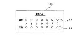
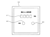
機械室には遊技球揚送装置1を含むパチンコ島全体を制御する管理装置が設けられており、これにカラーセンサ23の信号を受けて、搬送ベルト5の状態を報知する報知手段としての摩耗報知装置35が設けられている。
図5は摩耗報知装置35の一例を示すもので、A〜Gのカラーセンサ23それぞれについて、調整検出部材としての調整標識体31を検出したときに点灯する調整用表示灯36と、交換検出部材としての交換標識体32を検出したときに点灯する交換用表示灯37が設けられている。
【0058】
したがって、搬送ベルト5が摩耗し何れかのカラーセンサ23が調整標識体31を検出すると、この摩耗報知装置35に送信され、対応する調整用表示灯36が点灯する。また、交換標識体32を検出したときは同様に交換用表示灯37が点灯する。
【0059】
このように搬送ベルト5の幅方向の略全体に対向させて複数個のカラーセンサ23を設け、それぞれのカラーセンサ23の検出状態に基づいてそれぞれ報知する調整用表示灯36および交換用表示灯37を設けたので、次のようなことを推察することが可能となる。
【0060】
例えば、Cの交換用表示灯37のみが点灯した場合、釘などの異物が混入して搬送ベルト5が部分的に破損していることなどが推察され、搬送ベルト5の点検や交換作業などが必要なことを促すことができ、搬送ベルト5が切断して遊技球揚送装置1の部品などが破損される二次的被害などを防止できる。
【0061】
なお、この場合、交換標識体32よりもさらに内側(青、黒の層)まで搬送ベルト5が破損することが考えられるが、このような場合も交換用表示灯37が点灯するようにしておけばよい。
また、A,B,C3つの調整用表示灯36が点灯した場合、搬送ベルト5と研磨ベルトの間隔調整が両側方で均一になっていないことなどが推察され、再度、間隔調整が必要なことを促すことができ、不適切な間隔調整による搬送ベルト5の短命化を防止できる。
【0062】
また、上記したようなA〜Gの調整用表示灯36および交換用表示灯37の点灯パターンと推察される事項を対応させて記憶する記憶手段と、推察される事項がある点灯パターンの場合に推察される事項に関連する表示を行う表示手段を設けてもよい。これにより、点灯パターンを推察しなくても、推察される事項に関連する表示を自動的に行わせることができる。
【0063】
なお、上記実施の形態では、搬送ベルト5を種々の色彩の層で形成した多層のベルトで説明したが、色彩を使用せずに搬送ベルト5が交換すべき位置まで摩耗した位置に導電性(例えば鉄製)の摩耗検出部材を埋設し、磁気センサを摩耗検出手段としてもよい。この場合、磁気センサの出力が所定の値になると、研磨ベルトとの調整を促す調整用表示灯36を点灯させ、さらにそれより高いまたは低い所定の出力になると搬送ベルト5の交換を促す交換用表示灯37を点灯させるようにすればよい。
【0064】
また、検出は、遊技球揚送装置1が作動している間連続して行ってもよいが、一定時間毎に間欠的に行ってもよい。また、調整用表示灯36および交換用表示灯37を各1個として、何れかのカラーセンサ23または磁気センサが調整または交換を検出したときに点灯させるようにしてもよい。
また、カラーセンサ23は搬送ベルト5の幅方向の略全体に対向させて7つ設けたもので説明したが、適宜の個数であればよく、1つでもよい。
【0065】
次に参考例1について説明する。
図6に示すように、揚送筒体3にテンションローラ15の側面に立設するように取付部材27が、ボルト29で取り付けられている。揚送筒体3との取付部材27には位置調整穴28が形成されており、取付部材27はテンションローラ軸15aと直角方向に適宜の位置に取り付けることができる。
【0066】
取付部材27には伸長検出手段としての第1磁気センサ25と第2磁気センサ26が伸長検出部材としてのテンションローラ軸15aと同じ高さに位置させて設けられている。
また、テンションローラ軸15aと直角方向は搬送ベルト5が研磨部材としての研磨ベルトとの調整を必要とするほど伸長したときに、第1磁気センサ25がテンションローラ15aを検出し、さらに搬送ベルト5を交換すべきほど伸長したときに、第2磁気センサ26がテンションローラ軸15aを検出する位置に設定されている。
【0067】
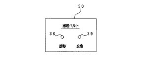
機械室には遊技球揚送装置1を含むパチンコ島全体を制御する管理装置が設けられており、これに第1磁気センサ25および第2磁気センサ26の信号を受けて、搬送ベルト5の状態を報知する報知手段としての伸長報知装置50が設けられている。
【0068】
図7は伸長報知装置50の一例を示すもので、第1磁気センサ25がテンションローラ軸15aを検出したときに点灯する調整用表示灯38と、第2磁気センサ26がテンションローラ軸15aを検出したときに点灯する交換用表示灯39が設けられている。
【0069】
このように構成されているので、搬送ベルト5が伸長するにつれ、バネ17で付勢されたテンションローラ軸15aがしだいに外方へ移動し、第1磁気センサ25がテンションローラ軸15aを検出すると、この伸長報知装置50に送信され、調整用表示灯38が点灯する。また、搬送ベルト5がさらに伸長し、第2磁気センサ26がテンションローラ軸15aを検出すると、交換用表示灯39が点灯する。
【0070】
したがって、調整用表示灯38が点灯したら、研磨ベルトとの調整作業を行い、交換用表示灯39が点灯したら、搬送ベルト5を交換すればよい。
なお、上記の実施の形態ではテンションローラ軸15aの移動を、第1磁気センサ25で検出するようにしたが、テンションローラ軸15aの端部に別部材の伸長検出部材を固設するとともに、揚送筒体3側の所定の位置に第1磁気センサ25および第2磁気センサ26に代わる伸長検出手段としてのリミットスイッチをそれぞれ設けて、伸長検出部材がリミットスイッチをONさせることにより調整用表示灯38、交換用表示灯39を点灯させるようにしてもよい。
【0071】
次に、参考例2について説明する。
図6および図8に示すように、下部ローラ4の近傍に取付部材21を設け、これに剥離検知手段としての距離センサ40が搬送ベルト5の幅方向に対向させて設けられている。
【0072】
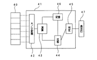
そして、遊技球揚送装置1の近傍に、距離センサ40の信号を入力してデータ処理を行い搬送ベルト5が剥離していることを判定するデータ処理装置41が設けられ、機械室の管理装置にはデータ処理装置41からの信号で搬送ベルト5が剥離していることを報知する報知手段としての表示灯47が設けられている。
【0073】
図8は剥離告知手段のブロック図で、データ処理装置41は各距離センサ40の検出信号をデジタル信号に変換するA/D変換器42と、距離センサ40から搬送ベルト5までの距離を演算する演算子43と、搬送ベルト5が正常であるときの基準距離データを記憶する記憶部46と、演算子43で演算された距離を基準距離データと比較する比較部44と、比較された値が所定の範囲内であるか否かを判定する判定部45とから構成されている。
【0074】
距離センサ40は搬送ベルト5の幅方向に複数個設けられており、それぞれ走査する幅を分担している。そして、距離センサ40から搬送ベルト5の表面までの距離信号を周期的に計測してデータ処理装置41へ送信している。
この距離信号はA/D変換器42でデジタル信号に変換され、演算子43で距離センサ40の走査している角度の情報を基に、搬送ベルト5に直角方向の距離に換算している。そして、比較部44では演算した距離データを記憶部46に記憶されている基準距離データとつきあわせ、その差を演算する。
【0075】
基準距離データは搬送ベルト5が取り付けられたときに測定した距離データである。
そして、判定部45では、その差が所定の値より大きい場合には表示灯47を点灯する信号を送出する。
【0076】
したがって、搬送ベルト5に剥離が発生すると、距離センサ40からの距離と基準距離との差が所定値より大きくなり、表示灯47が点灯する。
また、搬送ベルト5の幅方向の取り付け精度にズレが起こった場合にも表示灯47が点灯する。
【0077】
表示灯47が点灯したら、搬送ベルト5を点検し、交換や取り付け位置の修正を行えばよい。
なお、上記の参考例2では距離センサ40で剥離状態を検出するようにしたが、上記請求項1〜4の実施の形態のように、搬送ベルト5の色彩を変えた多層のベルトを使用し、剥離検出手段として距離センサ40に代えてカラーセンサを搬送ベルト5の幅方向に複数個設け、部分的に別の色彩を検出したときに剥離の可能性があることを報知するようにしてもよい。
【0078】
また、剥離検出手段として距離センサ40に代えて接触センサを搬送ベルト5の幅方向に設け、搬送ベルト5の表面に亀裂が発生して亀裂の端が飛び出し、これが接触センサに接触したときに剥離の可能性があることを報知するようにしてもよい。
【0079】
なお、参考例2を上記参考例1が記載されている図6で説明したが、参考例1とは当然個別に実施できるものである。
【0080】
次に、参考例3について図9〜図11に基づいて説明する。
遊技媒体揚送装置としての遊技球揚送装置1は上記説明したものと同じであり、図9に示すように、上部ローラ60と下部ローラ4に搬送ベルト5が巻回され、ベルト張力機構6を備えている。そして、下部ローラ4は駆動モータ52から伝動部材53を介して伝達されており、搬送ベルト5を循環駆動させている。
【0081】
下部ローラ4には駆動監視手段としての回転検出器55が設けられ、この検出信号を取り入れて積算し、所定値になると報知する報知手段としての報知装置56が設けられている。
報知装置56は図10に示すように、下部ローラ4の積算回転数を表示する積算値表示部57と、積算値が予め定めた搬送ベルト5の交換を要する値に到達すると点灯する表示灯58と、搬送ベルト5を更新したときにそれまでの積算回転数をゼロにするリセットスイッチ59が設けられており、内部にはこれらの信号を処理するためのCPUなどが格納されている。
【0082】
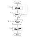
次に、報知装置56で行われる処理について、図11のフローチャートに基づいて説明する。
この処理は所定間隔(例えば100ms)で起動される。起動されると、ステップ100において、回転検出器55の信号を入力し、回転数を積算する。この積算値はメモリに記憶され、一定回転数(例えば100回転)に到達する毎に加算して積算値表示部57へ表示させる。
【0083】
ステップ110で、積算値が予めメモリに記憶されている搬送ベルト5の交換すべき基準値に到達しているか否かを判定する。ステップ110でNOと判定された場合は、ステップ100に戻り、さらに、積算が続けられる。
ステップ110でYESのときは、ステップ120へ進み、搬送ベルト5の交換を促す表示灯58を点灯させる。そして、リセットスイッチ59を押すと(ステップ130)、積算回転数をゼロにし、表示灯58を消灯させて処理を終了させる。
【0084】
なお、上記の参考例3では下部ローラ4の回転数を積算して搬送ベルト5の使用程度を把握したが、上部ローラ60の回転数、あるいは、搬送ベルト5の一カ所に検出部材を付設してこれの回数を積算するようにしてもよい。
また、駆動モータ52の通電時間を積算して、予め設定した搬送ベルト5を交換すべき時間に到達したら報知装置の表示灯を点灯させるようにしてもよい。
【0085】
また、上記の参考例3である下部ローラの積算回転数と、駆動モータ52の通電時間の積算値に基づいて、搬送ベルトの交換時期を設定することもできる。
また、リセットスイッチ59は、ベルト張力機構6にマイクロスイッチを設けてテンションローラを取り外したら自動的にリセットするようにしてもよい。
【0086】
以上の上記実施の形態では研磨部材として張設された研磨ベルトを示したが、遊技球を研磨できるものであればよく、例えば、ガイドレール7内部に樹脂製の突起を多数設けたものや、研磨ベルトが張設されておらず、ただ単にガイドレール7に敷設されたものでもよい。また、遊技球揚送装置は、摩耗告知手段、伸長告知手段、剥離告知手段および駆動監視手段をそれぞれ備えた実施の形態を示したが、全ての手段を備えたものでもよいし、1つまたは2つを組み合わせたものを備えたものでもよい。
【0087】
また、図5、図7および図10に示した摩耗報知装置35、伸長報知装置50および報知装置56は管理室や遊技球揚送装置に設けたもので説明したが、視認され易い位置であればよく、例えば、パチンコ島の上方に設けてもよい。
【図面の簡単な説明】
【図1】本発明の遊技媒体揚送装置の実施の形態の構成を表す斜視図である。
【図2】同 ガイドレールの揚送筒体への取付状態を示すもので、(a)は係止金具9の正面図、(b)は支持金具10の正面図である。
【図3】同 請求項1〜4の発明の実施の形態を示す斜視図である。
【図4】同 搬送ベルトの断面図である。
【図5】同 告知手段の平面図である。
【図6】参考例1および参考例2を示す斜視図である。
【図7】告知手段の平面図である。
【図8】参考例2の剥離告知手段のブロック図である。
【図9】参考例3を示す側面図である。
【図10】報知手段の平面図である。
【図11】報知手段における処理のフローチャートである。
【符号の説明】
1…遊技球揚送装置 2…支持台
3…揚送筒体 4…下部ローラ
5…搬送ベルト 6…ベルト張力機構
7…ガイドレール 8…排出口
9…係止金具 9a…金具
9b…係止レバー 9c…ピン
9d,9e…ボルト 10…支持金具
10a…金具 10b…ボルト
10c…受部
11a,11b…ベルト固定金具
12…導入樋 14…固定ローラ
15…テンションローラ
15a…テンションローラ軸
16…支持棒 17…バネ
18…固定ローラ 21…取付部材
23…カラーセンサ 25…第1磁気センサ
26…第2磁気センサ 27…取付部材
28…位置調整穴 29…ボルト
30…標識体 31…調整標識体
32…交換標識体 35…摩耗報知装置
36…調整用表示灯 37…交換用表示灯
38…調整用表示灯 39…交換用表示灯
40…接触センサ 41…データ処理装置
42…A/D変換器 43…演算子
44…比較部 45…判定部
46…記憶部 47…表示灯
50…伸長報知装置 52…駆動モータ
53…伝動部材 55…回転検出器
56…報知装置 57…積算値表示部
58…表示灯 59…リセットスイッチ
60…上部ローラ[0001]
BACKGROUND OF THE INVENTION
The present invention relates to a game medium lifting apparatus that lifts game media such as game balls and coins used in gaming machines such as pachinko machines and slot machines, and in particular, the transfer belt can be exchanged at an accurate time. This is related to the device.
[0002]
[Prior art]
For example, in a pachinko game hall, a plurality of pachinko machines are arranged to form a pachinko island, and the game balls discharged from each pachinko machine are gathered in the lower center of the pachinko island. A game medium lifting device is installed for lifting the collected game balls to the upper part of the pachinko island and distributing them again to each pachinko machine.
[0003]
This game medium transporting device includes a polishing belt wound around a roller provided at the top and bottom of a standing transporting cylinder, and is stretched up and down so as to face the transport belt. It is configured to be sandwiched between the conveying belt and the polishing belt to be transported.
[0004]
A driving means for circulatingly driving the conveyor belt and a belt tension mechanism for applying tension to the conveyor belt are provided in the lower part of the game medium lifting device, and when the conveyor belt is driven by the driving means, the game ball is separated from the polishing belt and the conveyor belt. In the meantime, the cigarette dust and dust adhering to the game ball are removed by adhering to the polishing belt.
[0005]
[Problems to be solved by the invention]
As described above, the abrasive belt removes the contamination of the game ball, so that the dirt is quickly and periodically changed (for example, every day).
On the other hand, since the conveyor belt is expensive and used for a long time, the conveyor belt is worn by contact with the game ball, or the conveyor belt is extended by the belt tension mechanism, so that the thickness is reduced and the abrasive belt is , And the game ball may not be securely clamped, and the carrying capacity may be reduced.
[0006]
In the amusement hall, the gap with the polishing belt is adjusted or the transport belt is replaced so that such a state does not occur. The timing for adjustment and replacement is determined based on experience by observing the state of the conveyor belt.
However, this judgment is quite difficult even for a skilled judge, and it is not accurate because it depends on the judge. For this reason, in general, adjustments and replacements are performed periodically over a period of time, and replacement work is requested by a specialized contractor because adjustment of the mounting position is troublesome.
[0007]
However, the thickness of the conveyor belt that needs to be adjusted or replaced may be reduced due to the temperature, humidity, or other environment at each game arcade, and the gap between the polishing belt and the game media transport device may be different. Therefore, it is different for each conveyor belt. Therefore, there is a problem that periodic adjustment work or replacement work is too early or too late.
[0008]
SUMMARY OF THE INVENTION An object of the present invention is to provide a game medium transporting apparatus that can determine an appropriate time when it is better to adjust the interval with the polishing member or replace the conveyor belt.
[0009]
[Means for solving the problems and effects]
Claims made to achieve the above object1In the described invention, a conveyor belt is wound around rollers provided at the upper and lower parts of a lifting cylinder, an abrasive member is provided opposite the conveyor belt, and a game medium is sandwiched between the conveyor belt and the abrasive member. In the game medium transporting apparatus for transporting, the transport belt is a multilayer belt having a plurality of layers having different colors for each layer, and a color sensor for detecting the color of the surface layer of the transport belt is provided on the transport belt. Multiple provided in the width directionStorage means for storing the detection patterns of the plurality of color sensors in correspondence with the states of the conveyance belt, and display means for displaying the states of the conveyance belts corresponding to the detection patterns of the plurality of color sensors.It is characterized by providing.
Claim2In the described invention, a conveyor belt is wound around rollers provided at the upper and lower parts of a lifting cylinder, an abrasive member is provided opposite the conveyor belt, and a game medium is sandwiched between the conveyor belt and the abrasive member. In the game medium transporting apparatus for transporting, the transport belt has a different color for each layer.More than 3 layersThe gist of the game medium transporting apparatus is a multilayer belt having layers, and includes a color sensor that detects the color of the surface layer of the transport belt for substantially the entire width of the transport belt.
Claim3In the described invention, a conveyor belt is wound around rollers provided at the upper and lower parts of a lifting cylinder, an abrasive member is provided opposite the conveyor belt, and a game medium is sandwiched between the conveyor belt and the abrasive member. In the game medium transporting apparatus for transporting, the transport belt has a different color for each layer.More than 3 layersThe gist of the game medium feeding device is a multilayer belt having a plurality of layers, and a plurality of color sensors for detecting the color of the surface layer of the transport belt in the width direction of the transport belt..
[0010]
In the present invention, for example, the conveyor belt may be layered, and a color that serves as a mark may be applied to a layer that appears on the surface when worn. This color may be applied to the entire conveyor belt or may be partial.In the present invention configured as described above, when the conveyor belt is worn down to a predetermined wear amount.PlaceIt is possible to easily determine that the wear has reached the constant wear amount. Therefore, for example, if the predetermined amount of wear is set at the replacement time of the conveyor belt, even a skilled judge such as observing the condition of the conveyor belt to determine whether or not to replace it does not perform complicated work. It is possible to easily determine whether or not it is appropriate to replace the conveyor belt for each game medium transport device, and based on this determination, it is possible to replace the conveyor belt at an appropriate time. In addition, if the predetermined wear amount is set as the adjustment timing of the game medium transporting device, it can be easily determined whether or not it is appropriate to perform the adjustment, and based on this determination, the game medium lifting is determined at an appropriate time. It is possible to adjust the interval of the feeding device. As a result, it is possible to maintain the game medium transport device in a good state.
[0011]
[0012]
[0013]
[0014]
[0015]
[0016]
[0017]
[0018]
[0019]
[0020]
[0021]
[0022]
[0023]
[0024]
[0025]
[0026]
[0027]
[0028]
[0029]
[0030]
[0031]
[0032]
In the present invention, a multi-layer belt having different colors is used as the conveyor belt, so that different colors appear on a part of the surface when peeling occurs. for that reason,In the present invention, the conveyance belt is peeled off.YongIt can be easily judged. Therefore, replacement of the conveyor belt can be urged when it is necessary to replace the conveyor belt quickly, such as when separation occurs due to foreign matter such as nails or when the conveyor belt is peeled off before it is cut. Thus, it is possible to prevent the circulation supply of game media from being damaged due to the discovery of peeling. Furthermore, secondary damage such as breakage of the parts of the game medium lifting device due to peeling of the conveyor belt can be prevented.
[0033]
[0034]
[0035]
[0036]
[0037]
[0038]
[0039]
[0040]
[0041]
[0042]
[0043]
[0044]
DETAILED DESCRIPTION OF THE INVENTION
Next, embodiments of the present invention will be described with reference to the drawings. FIG. 1 is a perspective view showing a configuration of a game
[0045]
As shown in FIG. 1, the game
[0046]
A
On the other hand, a
[0047]
In addition, an introduction rod 12 for arranging the game balls sent from the storage tank in a plurality of rows is provided in the lower part of the
Since it is configured in this way, the game ball that has flowed in from the introduction basket 12 is sandwiched between the
[0048]
Here, as shown in FIG. 2A, the metal fitting 9a for supporting the
[0049]
Further, as shown in FIG. 2B, the support metal fitting 10 provided on the other side surface of the
Since the slide plate 10a is fixed to the
[0050]
Adjustment of the gap between the conveying
This work will be described in detail. The two
[0051]
By such an operation, the gap interval between the
Next, as shown in FIG. 3, the
[0052]
The
[0053]
The
The outline of the game
[0054]
As shown in FIG. 4, the
[0055]
On the other hand, as shown in FIG. 3, in the vicinity of the
[0056]
The
[0057]
The machine room is provided with a management device for controlling the entire pachinko island including the game
FIG. 5 shows an example of the
[0058]
Accordingly, when the
[0059]
As described above, the plurality of
[0060]
For example, when only the C
[0061]
In this case, it is conceivable that the
In addition, when the three adjustment indicator lamps A, B, and C are lit, it is assumed that the interval adjustment between the conveying
[0062]
In addition, in the case of the storage pattern that stores the inferred items corresponding to the lighting patterns of the
[0063]
In the above embodiment, the multilayer belt in which the
[0064]
The detection may be performed continuously while the game
The seven
[0065]
nextReference example 1Will be described.
As shown in FIG. 6, the
[0066]
The
Further, when the
[0067]
The machine room is provided with a management device that controls the entire pachinko island including the game
[0068]
FIG. 7 shows an example of the
[0069]
With this configuration, as the
[0070]
Therefore, when the
In the above-described embodiment, the movement of the tension roller shaft 15a is detected by the first
[0071]
next,Reference example 2Will be described.
As shown in FIGS. 6 and 8, a mounting
[0072]
A data processing device 41 is provided in the vicinity of the game
[0073]
FIG. 8 is a block diagram of the peeling notification means. The data processing device 41 calculates an A / D converter 42 that converts detection signals of the
[0074]
A plurality of
This distance signal is converted into a digital signal by the A / D converter 42, and converted to a distance perpendicular to the
[0075]
The reference distance data is distance data measured when the
And the
[0076]
Therefore, when peeling occurs on the
The
[0077]
When the
Note that the aboveReference example 2Then, the
[0078]
Further, a contact sensor is provided in the width direction of the
[0079]
In addition,Reference example 2The aboveReference example 1Is described in FIG.Reference example 1Of course, it can be implemented individually.
[0080]
next,Reference example 3Will be described with reference to FIGS.
The game
[0081]
The
As shown in FIG. 10, the
[0082]
Next, processing performed by the
This process is started at a predetermined interval (for example, 100 ms). When activated, in step 100, the signal of the
[0083]
In step 110, it is determined whether or not the integrated value has reached a reference value to be exchanged for the
If YES in step 110, the process proceeds to step 120, and the indicator lamp 58 that prompts replacement of the
[0084]
Note that the aboveReference example 3Then, the number of rotations of the
Further, the energization time of the
[0085]
Also aboveReference example 3Based on the integrated rotation number of the lower roller and the integrated value of the energization time of the
Further, the
[0086]
In the above embodiment, the polishing belt stretched as the polishing member has been shown. However, any polishing ball can be used as long as it can polish the game ball, for example, a
[0087]
In addition, although the
[Brief description of the drawings]
FIG. 1 is a perspective view showing a configuration of an embodiment of a game medium lifting device of the present invention.
FIGS. 2A and 2B show a state in which the guide rail is attached to a lifting cylinder, in which FIG. 2A is a front view of a
FIG. 3~ 4It is a perspective view which shows embodiment of this invention.
FIG. 4 is a sectional view of the conveyance belt.
FIG. 5 is a plan view of the notification means.
[Fig. 6]Reference example 1andReference example 2FIG.
[Fig. 7]NoticeIt is a top view of a knowledge means.
[Fig. 8]Reference example 2It is a block diagram of the peeling notification means.
FIG. 9Reference example 3FIG.
FIG. 10NewsIt is a top view of a knowledge means.
FIG. 11NewsIt is a flowchart of the process in a knowledge means.
[Explanation of symbols]
1 ... Game
3 ... Lifting
5 ...
7 ...
9: Locking bracket 9a: Bracket
9b ... Locking lever 9c ... Pin
9d, 9e ... bolt 10 ... support bracket
10a ... Fitting 10b ... Bolt
10c ... receiving part
11a, 11b ... Belt fixing bracket
12 ...
15 ... Tension roller
15a ... tension roller shaft
16 ...
18 ...
23 ...
26 ... Second
28 ...
30 ... Marking
32 ...
36 ... Indicator light for
38 ... Indicator light for
40 ... contact sensor 41 ... data processing device
42 ... A /
44:
46 ...
50 ...
53 ...
56 ...
58 ...
60 ... Upper roller
Claims (3)
前記搬送ベルトは、層ごとに色彩が異なる複数層を有する多層のベルトであるとともに、
前記搬送ベルトの表層の色を検出するカラーセンサを、前記搬送ベルトの幅方向に複数備え、
前記複数のカラーセンサの検出パターンと、前記搬送ベルトの状態とを対応させて記憶する記憶手段を備え、前記複数のカラーセンサの検出パターンに対応する前記搬送ベルトの状態を表示する表示手段を備えることを特徴とする遊技媒体揚送装置。A game medium in which a conveyor belt is wound around rollers provided at the top and bottom of a lifting cylinder, an abrasive member is provided opposite to the conveyor belt, and a game medium is sandwiched between the conveyor belt and the abrasive member to be transported In the lifting device,
The conveyor belt is a multilayer belt having a plurality of layers with different colors for each layer, and
A plurality of color sensors for detecting the color of the surface layer of the transport belt are provided in the width direction of the transport belt ,
Storage means for storing the detection patterns of the plurality of color sensors and the states of the conveyance belts in association with each other, and display means for displaying the states of the conveyance belts corresponding to the detection patterns of the plurality of color sensors. A game medium lifting device characterized by the above.
前記搬送ベルトは、層ごとに色彩が異なる3層以上の層を有する多層のベルトであるとともに、
前記搬送ベルトの幅方向の略全体について、前記搬送ベルトの表層の色を検出するカラーセンサを備えることを特徴とする遊技媒体揚送装置。A game medium in which a conveyor belt is wound around rollers provided at the top and bottom of a lifting cylinder, an abrasive member is provided opposite to the conveyor belt, and a game medium is sandwiched between the conveyor belt and the abrasive member to be transported In the lifting device,
The conveyor belt is a multilayer belt having three or more layers having different colors for each layer , and
A game medium transporting apparatus comprising a color sensor for detecting a color of a surface layer of the transport belt for substantially the entire width of the transport belt.
前記搬送ベルトは、層ごとに色彩が異なる3層以上の層を有する多層のベルトであるとともに、
前記搬送ベルトの表層の色を検出するカラーセンサを、前記搬送ベルトの幅方向に複数備えることを特徴とする遊技媒体揚送装置。A game medium in which a conveyor belt is wound around rollers provided at the top and bottom of a lifting cylinder, an abrasive member is provided opposite to the conveyor belt, and a game medium is sandwiched between the conveyor belt and the abrasive member to be transported In the lifting device,
The conveyor belt is a multilayer belt having three or more layers having different colors for each layer , and
A game medium transporting apparatus comprising a plurality of color sensors for detecting a color of a surface layer of the transport belt in a width direction of the transport belt.
Priority Applications (1)
| Application Number | Priority Date | Filing Date | Title |
|---|---|---|---|
| JP2001359362A JP4269552B2 (en) | 2001-11-26 | 2001-11-26 | Game media lifting device |
Applications Claiming Priority (1)
| Application Number | Priority Date | Filing Date | Title |
|---|---|---|---|
| JP2001359362A JP4269552B2 (en) | 2001-11-26 | 2001-11-26 | Game media lifting device |
Publications (2)
| Publication Number | Publication Date |
|---|---|
| JP2003154148A JP2003154148A (en) | 2003-05-27 |
| JP4269552B2 true JP4269552B2 (en) | 2009-05-27 |
Family
ID=19170389
Family Applications (1)
| Application Number | Title | Priority Date | Filing Date |
|---|---|---|---|
| JP2001359362A Expired - Fee Related JP4269552B2 (en) | 2001-11-26 | 2001-11-26 | Game media lifting device |
Country Status (1)
| Country | Link |
|---|---|
| JP (1) | JP4269552B2 (en) |
Families Citing this family (4)
| Publication number | Priority date | Publication date | Assignee | Title |
|---|---|---|---|---|
| JP2012177991A (en) * | 2011-02-25 | 2012-09-13 | Sinfonia Technology Co Ltd | Paper sheet processing device |
| JP5957215B2 (en) * | 2011-12-02 | 2016-07-27 | 株式会社ブリヂストン | Conveyor belt equipment |
| JP5985132B1 (en) * | 2015-03-13 | 2016-09-06 | オリンパス株式会社 | Driving force transmission mechanism |
| JP7170568B2 (en) * | 2019-03-19 | 2022-11-14 | 株式会社東芝 | Paper sheet processing device and paper sheet processing method |
-
2001
- 2001-11-26 JP JP2001359362A patent/JP4269552B2/en not_active Expired - Fee Related
Also Published As
| Publication number | Publication date |
|---|---|
| JP2003154148A (en) | 2003-05-27 |
Similar Documents
| Publication | Publication Date | Title |
|---|---|---|
| JP4159622B2 (en) | Equipment for polishing gaming media | |
| JP4269552B2 (en) | Game media lifting device | |
| JP5844960B2 (en) | Game machine | |
| JP6121505B2 (en) | Game machine | |
| US20190224804A1 (en) | Machining apparatus having a light signal display device, and method | |
| US7383934B2 (en) | Apparatus for supporting objects to identify | |
| TWI745887B (en) | Game console | |
| JP3659266B2 (en) | Medal dropping game machine | |
| JP2004215730A (en) | Game machine | |
| KR102189218B1 (en) | Auto Assembling Apparatus of Crescent | |
| CA2115030C (en) | Medal piece feed system for game machine | |
| JP4152453B2 (en) | Polishing equipment | |
| JPH10277248A (en) | Ball polishing and lifting device | |
| JP4463746B2 (en) | Game machine | |
| EP1178291A2 (en) | Weight inspecting apparatus | |
| JP3901044B2 (en) | Tamaki hoisting device | |
| JP5155316B2 (en) | Bill recognition device and control method thereof | |
| CN111247881A (en) | Notification device and notification method | |
| JP5569149B2 (en) | Polishing belt movement control system | |
| JP4078681B2 (en) | Ball lifting device | |
| JP3854785B2 (en) | Display unit and game machine | |
| JP4159623B2 (en) | Game media polishing equipment | |
| JP4093203B2 (en) | Tamaki hoisting device | |
| JP2006326332A (en) | Ball polishing and pumping apparatus | |
| JP2006297157A (en) | Ball polishing hoisting device |
Legal Events
| Date | Code | Title | Description |
|---|---|---|---|
| A621 | Written request for application examination |
Free format text: JAPANESE INTERMEDIATE CODE: A621 Effective date: 20041019 |
|
| A977 | Report on retrieval |
Free format text: JAPANESE INTERMEDIATE CODE: A971007 Effective date: 20080221 |
|
| A131 | Notification of reasons for refusal |
Free format text: JAPANESE INTERMEDIATE CODE: A131 Effective date: 20080415 |
|
| A521 | Written amendment |
Free format text: JAPANESE INTERMEDIATE CODE: A523 Effective date: 20080604 |
|
| A131 | Notification of reasons for refusal |
Free format text: JAPANESE INTERMEDIATE CODE: A131 Effective date: 20081111 |
|
| A521 | Written amendment |
Free format text: JAPANESE INTERMEDIATE CODE: A523 Effective date: 20081224 |
|
| TRDD | Decision of grant or rejection written | ||
| A01 | Written decision to grant a patent or to grant a registration (utility model) |
Free format text: JAPANESE INTERMEDIATE CODE: A01 Effective date: 20090203 |
|
| A01 | Written decision to grant a patent or to grant a registration (utility model) |
Free format text: JAPANESE INTERMEDIATE CODE: A01 |
|
| A61 | First payment of annual fees (during grant procedure) |
Free format text: JAPANESE INTERMEDIATE CODE: A61 Effective date: 20090216 |
|
| FPAY | Renewal fee payment (event date is renewal date of database) |
Free format text: PAYMENT UNTIL: 20120306 Year of fee payment: 3 |
|
| R150 | Certificate of patent or registration of utility model |
Ref document number: 4269552 Country of ref document: JP Free format text: JAPANESE INTERMEDIATE CODE: R150 Free format text: JAPANESE INTERMEDIATE CODE: R150 |
|
| FPAY | Renewal fee payment (event date is renewal date of database) |
Free format text: PAYMENT UNTIL: 20130306 Year of fee payment: 4 |
|
| LAPS | Cancellation because of no payment of annual fees |