JP4268524B2 - Blind signal separation - Google Patents
Blind signal separation Download PDFInfo
- Publication number
- JP4268524B2 JP4268524B2 JP2003572174A JP2003572174A JP4268524B2 JP 4268524 B2 JP4268524 B2 JP 4268524B2 JP 2003572174 A JP2003572174 A JP 2003572174A JP 2003572174 A JP2003572174 A JP 2003572174A JP 4268524 B2 JP4268524 B2 JP 4268524B2
- Authority
- JP
- Japan
- Prior art keywords
- signal
- delay
- matrix
- rotation
- signals
- Prior art date
- Legal status (The legal status is an assumption and is not a legal conclusion. Google has not performed a legal analysis and makes no representation as to the accuracy of the status listed.)
- Expired - Lifetime
Links
Images

Classifications
-
- H—ELECTRICITY
- H03—ELECTRONIC CIRCUITRY
- H03H—IMPEDANCE NETWORKS, e.g. RESONANT CIRCUITS; RESONATORS
- H03H21/00—Adaptive networks
- H03H21/0012—Digital adaptive filters
-
- G—PHYSICS
- G06—COMPUTING; CALCULATING OR COUNTING
- G06F—ELECTRIC DIGITAL DATA PROCESSING
- G06F18/00—Pattern recognition
- G06F18/20—Analysing
- G06F18/21—Design or setup of recognition systems or techniques; Extraction of features in feature space; Blind source separation
- G06F18/213—Feature extraction, e.g. by transforming the feature space; Summarisation; Mappings, e.g. subspace methods
- G06F18/2134—Feature extraction, e.g. by transforming the feature space; Summarisation; Mappings, e.g. subspace methods based on separation criteria, e.g. independent component analysis
Landscapes
- Engineering & Computer Science (AREA)
- Computer Vision & Pattern Recognition (AREA)
- Data Mining & Analysis (AREA)
- Theoretical Computer Science (AREA)
- General Engineering & Computer Science (AREA)
- Bioinformatics & Cheminformatics (AREA)
- Bioinformatics & Computational Biology (AREA)
- Evolutionary Biology (AREA)
- Evolutionary Computation (AREA)
- Physics & Mathematics (AREA)
- Artificial Intelligence (AREA)
- General Physics & Mathematics (AREA)
- Life Sciences & Earth Sciences (AREA)
- Complex Calculations (AREA)
- Optical Communication System (AREA)
- Ultra Sonic Daignosis Equipment (AREA)
- Measurement Of Velocity Or Position Using Acoustic Or Ultrasonic Waves (AREA)
- Measurement Of Mechanical Vibrations Or Ultrasonic Waves (AREA)
- Amplifiers (AREA)
- Control Of Motors That Do Not Use Commutators (AREA)
- Reduction Or Emphasis Of Bandwidth Of Signals (AREA)
- Circuit For Audible Band Transducer (AREA)
Abstract
Description
本発明はブラインド信号分離に関し、より詳細には畳み込み混合された信号のブラインド信号分離、及びこれを実施するための方法、装置、及びコンピュータプログラムに関する。 The present invention relates to blind signal separation, and more particularly to blind signal separation of convolutionally mixed signals, and methods, apparatus, and computer programs for implementing the same.
ブラインド信号分離は公知であり、すなわち、コンピュータシステム上で動作し、アナログ形式からディジタル形式に変換された後にセンサからデータを受け取るソフトウエアによって実行される信号処理の形態である。「ブラインド」という表現は、混合される信号は混合の前には統計的に独立していたという仮定以外には、信号特性又は信号を混合する処理について何も仮定されないことを表している。信号を互いに分離する多くの手法が存在し、これらは信号特性の事前知識に依存する。事前知識は、信号の到来方向、周波数、波形、タイミング、振幅変調などである。しかしながら、ブラインド信号分離に唯一必要なものは信号が統計的に独立していることであり、これは通常は実際の場合において成立する現実的な仮説である。すなわち、その信号の1つについての情報が他から取得することができず、及び信号の部分集合についての情報が集合内の別の信号値の知識から導出することのできない場合は、1つの集合の信号は統計的に独立していることになる。 Blind signal separation is well known, i.e., a form of signal processing performed by software that runs on a computer system and receives data from sensors after being converted from analog to digital form. The expression “blind” means that no assumptions are made about the signal characteristics or the process of mixing the signals other than the assumption that the signals to be mixed were statistically independent prior to mixing. There are many ways to separate signals from each other, which depend on prior knowledge of signal characteristics. Prior knowledge includes signal arrival direction, frequency, waveform, timing, amplitude modulation, and the like. However, the only requirement for blind signal separation is that the signals are statistically independent, which is a realistic hypothesis that usually holds in real cases. That is, one set if the information about one of the signals cannot be obtained from the other and the information about the subset of signals cannot be derived from knowledge of another signal value in the set. Will be statistically independent.
通常、定常性及び直線性といった2つの別の仮定がブラインド信号分離でなされ、これらの仮定も本発明と関連してなされる。定常性とは、信号及び該信号が混合されるチャネルが、混合信号がサンプリングされる間の時間間隔にわたって変化しないことを意味する。直線性とは、センサによって受け取られた混合信号が、これらの信号の一次結合であることを意味する。信号の積及び平方並びに信号のより高いオーダの累乗を特徴とするより複雑な結合は考慮されていない。 Two other assumptions are usually made with blind signal separation, such as stationarity and linearity, and these assumptions are also made in connection with the present invention. Stationary means that the signal and the channel in which it is mixed do not change over the time interval during which the mixed signal is sampled. Linearity means that the mixed signal received by the sensor is a linear combination of these signals. More complex combinations characterized by signal product and square and higher order powers of the signal are not considered.
ブラインド信号分離の目的は、混合前の信号、すなわち源信号を復元することである。この手法はまた、独立成分分析(ICA)として知られており、これは本明細書の目的のブラインド信号分離と同義語として扱われる。目的が混合信号を互いに分離することなので、ブラインド信号分離は「逆混合」と呼ばれる場合がある。 The purpose of blind signal separation is to restore the signal before mixing, ie the source signal. This technique is also known as Independent Component Analysis (ICA), which is treated as a synonym for blind signal separation for purposes herein. Blind signal separation is sometimes referred to as “inverse mixing” because the purpose is to separate the mixed signals from each other.
ブラインド信号分離の用途の簡単な実施例は、2つの受信マイクロフォンに送信する2つのラウドスピーカ(拡声器)を含むものである。マイクロフォンは、両方のラウドスピーカからの混合信号を受け取り生成するが、ラウドスピーカから受信機までの経路が異なるので混合されたものは異なっている。両方のラウドスピーカが音声信号を伝送する場合、いずれかの受信機の出力を単独で理解することは、困難であるか、或いは不可能でさえある。 A simple example of the use of blind signal separation includes two loudspeakers that transmit to two receiving microphones. The microphone receives and generates mixed signals from both loudspeakers, but the mixed ones are different because of the different paths from the loudspeakers to the receiver. If both loudspeakers carry audio signals, it is difficult or even impossible to understand the output of either receiver alone.
同様の問題は、RF受信機によって受け取られた共チャネル無線信号の分離、加速度計によって計測された機械振動信号の分離、又は株式相場の引き際における根底にある要因の発見において見られる可能性がある。これら全ての状況の場合に、センサを駆動する幾つかの信号が存在し、又は最後の例の場合では、価格に影響を及ぼす幾つかの変動要素が存在し得る。 Similar problems may be found in the separation of co-channel radio signals received by RF receivers, the separation of mechanical vibration signals measured by accelerometers, or the discovery of the underlying factors in the course of stock quotes. . In all these situations there may be some signal driving the sensor, or in the last example there may be some variables that affect the price.
統計的な独立性は、混合信号の結合確率密度関数を信号の個々の確率密度関数の積に因数分解できることとして説明することができる。ブラインド信号分離問題の最も簡単な形態は瞬時混合問題と呼ばれ、すなわち、各信号とセンサの集合の各々との間の伝播遅延は、その信号の同じ時間サンプルに適用された単純な位相シフトとして表すことができる。 Statistical independence can be explained as the combined probability density function of a mixed signal can be factored into the product of the individual probability density functions of the signal. The simplest form of the blind signal separation problem is called the instantaneous mixing problem, that is, the propagation delay between each signal and each of the set of sensors is as a simple phase shift applied to the same time sample of that signal. Can be represented.
瞬時混合問題(以後「瞬時アルゴリズム」という)を解決する多くの異なるアルゴリズムは、文献において見いだすことができる。良く知られた瞬時アルゴリズムの幾つかは、JADE、SOBI、BLISS、及び高速ICAと呼ばれ、以下の引例で定義されている。 Many different algorithms for solving the instantaneous mixing problem (hereinafter referred to as “instantaneous algorithms”) can be found in the literature. Some of the well-known instantaneous algorithms are called JADE, SOBI, BLISS, and fast ICA and are defined in the following references.
「JADE」: J F Cardoso and A Souloumiac, 「Blind Beamforming for non−Gaussian signals」,IEEE proceedings−F Vol.140 No.6(1993年12月)
「SOBI」: A Belouchrani, K Abed−Meraimm, J Cardoso and E Moulines, 「A Blind Source Separation Technique UsingSecond Order Statictics」, IEEE transactions on signal processing, Vol.45 No.2(1997年2月)
「BLISS」: I.J. Clarke, 「Direct Exploitation of non−Gaussianity as a Discriminant」, EUSIPCO 1998(1998年9月)
「高速ICA」: A. Hyvarinen, E. Oja, 「A Fast Fixed−Point Algorithm for Independent Component Analysis」, Neural Computation 9, P1483−1492(1997年)
“JADE”: J F Cardoso and A Souloumiac, “Blind Beamforming for non-Gaussian signals”, IEEE processings-F Vol. 140 No. 6 (December 1993)
“SOBI”: A Belochrani, K Abbed-Meraim, J Cardoso and E Moulins, “A Blind Source Separation Technology OrderElectricsEt. 45 No. 2 (February 1997)
“BLISS”: J. et al. Clarke, “Direct Exploration of Non-Gaussianity as a Discriminant,” EUSIPCO 1998 (September 1998)
“High-speed ICA”: Hyvarinen, E .; Oja, “A Fast Fixed-Point Algorithm for Independent Component Analysis”, Neural Computation 9, P1483-1492 (1997)
これらの瞬時アルゴリズムは、その後にユニタリ回転段階が続く2オーダの非相関段階を含む2段階構造(必須ではないが)を有する。2オーダの非相関段階は2オーダの独立性を与えるように意図され、ユニタリ回転段階は、2オーダの独立性には影響を及ぼさずより高いオーダの独立性を与えることが意図されている。 These instantaneous algorithms have a two-stage structure (although not essential) that includes a two-order decorrelation stage followed by a unitary rotation stage. The two-order decorrelation stage is intended to give two orders of independence, and the unitary rotation stage is intended to give higher order independence without affecting the two-order independence.
2オーダの非相関段階は、信号の非相関化及び正規化から成る。非相関性は、信号の集合内の信号ペア間で全ての相関性又は類似性を排除するプロセスであり、相関性は、信号の積の時間積分として数学的に定義される。正規化は信号の集合内の信号を同じ出力レベルにするプロセスである。 The two-order decorrelation stage consists of signal decorrelation and normalization. Uncorrelation is the process of eliminating all correlations or similarities between signal pairs in a set of signals, where correlation is mathematically defined as the time integral of the signal product. Normalization is the process of bringing the signals in a set of signals to the same output level.
非相関化と正規化との組み合せにより、2オーダの統計的独立性が確立される。この後信号は回転を受ける。混合されるようになると、信号は、回転、伸張、及びずれが複雑に組み合されたプロセス(信号を分離するために影響を排除しなければならない)を受ける。非相関性は、伸張とずれの影響を排除するので、信号の分離には回転だけを適用する必要がある。回転は、ずれ又は伸張を適用することができず、従って非相関性の影響をうち消すことはできない。 The combination of decorrelation and normalization establishes two orders of statistical independence. After this, the signal undergoes rotation. Once mixed, the signal is subjected to a process that is a complex combination of rotation, stretching, and misalignment (effects must be eliminated to separate the signals). Since decorrelation eliminates the effects of stretching and misalignment, only rotation needs to be applied for signal separation. Rotation cannot apply offsets or stretches and therefore cannot cancel the effects of decorrelation.
例えば、2オーダの独立性が全体の独立性を意味するガウス確率密度関数を各々が有する2つの混合信号に対して、適切な回転を見つけることが不可能である場合がある。これはガウス分布が2オーダよりも大きな依存性を生じないことによる。従って、ガウス確率密度関数を有する2つの独立信号は、全回転の対称性を有し、結果的にいかなる角度の回転によっても完全に不変の結合確率密度関数を有する。 For example, it may be impossible to find an appropriate rotation for two mixed signals, each having a Gaussian probability density function, where two orders of independence mean total independence. This is because the Gaussian distribution does not produce a dependency larger than 2 orders. Thus, two independent signals with a Gaussian probability density function have full-rotation symmetry, resulting in a joint probability density function that is completely invariant with any angular rotation.
従って、従来技術の瞬時アルゴリズムの2オーダ又はより高いオーダの段階では、信号に対してより高いオーダの独立性を復元させるユニタリ行列を実行する回転を探索する。 Therefore, in the two-order or higher order stage of the prior art instantaneous algorithm, we search for a rotation that performs a unitary matrix that restores higher order independence to the signal.
「Extended Quasi−Newton Method for the ICA」と題されたT.Akuzawaの1つの引例(http://mns.brain.riken.go.jp/〜akuzawa/publ/htmから前刷りを入手可能である)では、非相関性を使用しないアルゴリズムを提案している。代わりに、依存性の4オーダの測定値を最小化する勾配降下手法が提案されている。A.Yeredorはまた、「Approximate Joint Diagonalisation Using Non−Orthoganal Matrices」,Proc ICA2000 p33−38, Helsinki,Finlandで非相関性を排除しているが、2オーダ及び4オーダの両オーダの依存性に基づく測定値を最小化する手法を使用している。これにより4オーダの依存性と同様に相関を取り扱うことができる。 T., entitled “Extended Quasi-Newton Method for the ICA”. One reference to Akuzawa (http://mns.brain.riken.go.jp/˜preprints are available from Akuzawa / publ / html) proposes an algorithm that does not use decorrelation. Instead, a gradient descent technique has been proposed that minimizes the 4-order measurement of dependency. A. Yeredor also excludes non-correlation in “Approximate Joint Diagnosis Using Non-Orthogonal Matrices”, Proc ICA2000 p33-38, Helsinki, Finland, but is based on two-order and four-order values. The technique that minimizes is used. As a result, the correlation can be handled in the same manner as the 4-order dependency.
P.Comonは、「Independent Component Analysis,A new concept?」において非相関性を使用した閉型解法を開示している。Comonは、ユニタリ行列の2×2の4要素サブブロックを繰り返して掃き出すことによって、全ユニタリ行列を一度に見つけることを試みている。この目的は、独立した4オーダの測定値を最大化することである。J F CardosoとA Souloumiacは、「Blind Beamforming for non−Gaussian signals」,IEEE proceedings−F,Vol.140,No.6(1993年12月)において「JADE」と呼ばれるアルゴリズムの生成を開示している。JADEはComonのアルゴリズムと類似しているが、結合近似対角化を使用するのでより高速である。 P. Comon discloses a closed-type solution using decorrelation in "Independent Component Analysis, A new concept?". Comon attempts to find all unitary matrices at once by repeatedly sweeping out 2 × 2 four-element sub-blocks of the unitary matrix. The purpose is to maximize the measurement of independent 4 orders. J F Cardoso and A Souloumiac, “Blind Beamforming for non-Gaussian signals”, IEEE proceedings-F, Vol. 140, no. 6 (December 1993) discloses the generation of an algorithm called “JADE”. JADE is similar to Common's algorithm, but is faster because it uses joint approximate diagonalization.
Belouchrani他は、「A Blind Source Separation Technique Using Second Order Statictics」,IEEE transactions on signal processing,Vol.45,No.2(1997年2月)においてSOBIアルゴリズムを生成するためのJADEアルゴリズムの修正を開示している。SOBIアルゴリズムは、その目的関数においてのみJADEアルゴリズムと異なり、これは最大化されるべき2オーダの測定値である。これはまた、結合対角化を使用することによるJADEアルゴリズムの速度面での利点を有する。しかしながら、SOBIは異なるスペクトル情報を保持する信号に依存し、かつ依存しない場合には機能しない。 Belouchrani et al., “A Blind Source Separation Technology Second Order Statics”, IEEE transactions on signal processing, Vol. 45, no. 2 (February 1997) discloses a modification of the JADE algorithm to generate the SOBI algorithm. The SOBI algorithm differs from the JADE algorithm only in its objective function, which is a two-order measurement to be maximized. This also has the speed advantage of the JADE algorithm by using joint diagonalization. However, SOBI relies on signals holding different spectral information and will not work if it does not.
「A Fast Fixed−Point Algorithm for Independent Component Analysis」,Neural Computation 9,P1483−1492(1997年)においてA Hyvarinen,E.Ojaは、高速ICAアルゴリズムと呼ばれるアルゴリズムを開示している。このアルゴリズムは、信号非相関性を使用し、1回で1行のユニタリマトリクスを形成することによって回転の実行を試みている。適切な回転を決定するために、このアルゴリズムは、独立した4オーダの測定値又は非線形性に基づく独立性の測定値である目標関数内の最大値を探索する。 In “A Fast Fixed-Point Algorithm for Independent Component Analysis”, Neural Computation 9, P1483-1492 (1997), A Hyvarenen, E. et al. Oja discloses an algorithm called the fast ICA algorithm. This algorithm uses signal decorrelation and attempts to perform rotation by forming a single row of unitary matrices at a time. In order to determine the appropriate rotation, the algorithm searches for the maximum value in the objective function, which is an independent 4-order measurement or an independent measurement based on non-linearity.
高速ICAに関する変形形態は、A.Hyvarinenの「Complexity Pursuit:Combining Nongaussianity and Autocorrelations for Signal Separation」,ICA2000,P567−572,Helsinki,Finland(2000年6月)によって最近提案されている。回転を決定するために、独立性ではなく複雑性(Komogoroff)の最大値を探索する。 Variations on high speed ICA include A. Recently proposed by Hyvarinen, “Complexity Pursuit: Combining Nongaussianities and Automation for Signal Separation”, ICA 2000, P567-572, Helsinki, Finland (June 2000). To determine the rotation, we search for the maximum value of complexity (Komogoroff) rather than independence.
「Direct Exploitation of non−Gaussianity as a Discriminant」,EUSIPCO,1998(1998年9月)においてI.J.Clarkeは、BLISSと呼ばれるアルゴリズムを開示している。これは信号の非相関性を使用し、JADE及びSOBIと同様に一対の掃き出しを実行する。BLISSは、回転を決定するために、推定結合確率密度関数とプロットされた座標系の軸との位置合わせに基づいて目的関数内で最大値を探索し、これは必要な回転を明示的に見つける。 In “Direct Exploration of Non-Gaussianity as a Discriminant”, EUSIPCO, 1998 (September 1998), I.I. J. et al. Clarke discloses an algorithm called BLISS. This uses signal decorrelation and performs a pair of sweeps similar to JADE and SOBI. BLISS searches for a maximum value in the objective function based on the alignment of the estimated joint probability density function with the axes of the plotted coordinate system to determine the rotation, which explicitly finds the required rotation. .
残念なことに、瞬時混合問題に好適なアルゴリズムは、より困難な問題を処理することはできない。こうしたより困難な問題は、センサの出力を数学的に畳み込みとして表す必要がある場合、すなわち、連続したレプリカ信号の組み合せが互いに相対的に遅延する場合に生じる。 Unfortunately, an algorithm suitable for the instantaneous mixing problem cannot handle more difficult problems. These more difficult problems arise when the sensor output needs to be expressed mathematically as a convolution, i.e., when successive replica signal combinations are delayed relative to each other.
畳み込み混合された信号のブラインド信号分離は、極めて最新の研究分野である。幾つかの手法が提案されてきたが、その幾つかは、ある特定の集合の状況では成功している。これらの手法は傾向としては低速であり、成立させるためには追加の仮定が必要であり、大きさ/収束問題を有する場合が多い。 Blind signal separation of convolution mixed signals is a very new research area. Several approaches have been proposed, some of which have been successful in certain set situations. These approaches tend to be slow, require additional assumptions to be successful, and often have size / convergence problems.
瞬時アルゴリズムに使用される手法は、畳み込み混合の場合にまで拡張された。この手法から、畳み込み混合信号は2段階のアルゴリズムによって逆混合し得ることが推論され、第1段階は2オーダの独立性を与え、第2段階はより高いオーダの独立性を与えるが2オーダの独立性には影響を与えない。このアルゴリズムは混合及び逆混合に含まれる時間遅延に適応する。第1段階として、混合信号を多チャネル格子フィルタによって変換して非相関化及び白色化された信号を取得することができる。これに関して、信号の白色化は、信号が全周波数で同じ出力を有するようにすることを含む。信号の集合を白色化することは、このような信号を全て個別に白色化することを意味する。 The technique used for the instantaneous algorithm has been extended to the case of convolutional mixing. From this approach, it is inferred that the convolutional mixed signal can be backmixed by a two-stage algorithm, where the first stage gives two orders of independence and the second stage gives higher orders of independence but two orders of independence. Does not affect independence. This algorithm adapts to the time delays involved in mixing and demixing. As a first step, the mixed signal can be transformed by a multi-channel grating filter to obtain a decorrelated and whitened signal. In this regard, signal whitening involves ensuring that the signal has the same output at all frequencies. Whitening a set of signals means whitening all such signals individually.
瞬時アルゴリズムに使用されたユニタリ行列の代わりに、畳み込み逆混合アルゴリズムの第2段階は、パラユニタリ行列を用いる。以下でより詳細に説明するように、パラユニタリ行列は、そのパラ共役行列、すなわちエルミート共役行列に相当する多項式行列と乗算すると、単位行列を与える多項式行列である。従って、畳み込み混合問題に対する実行可能な手法は、多チャネル格子フィルタを適用して、2オーダの独立性と白色化を与え、次いで、4オーダ又はより高いオーダの独立性の測定値を最大化するパラユニタリ行列を探索することである。 Instead of the unitary matrix used for the instantaneous algorithm, the second stage of the convolutional demixing algorithm uses a paraunitary matrix. As described in more detail below, a paraunitary matrix is a polynomial matrix that, when multiplied by its paraconjugate matrix, ie, a polynomial matrix corresponding to a Hermitian conjugate matrix, gives a unit matrix. Thus, a feasible approach to the convolutional mixing problem applies a multi-channel grid filter to give 2 orders of independence and whitening, and then maximize 4 or higher order independence measurements. Search for paraunitary matrices.
従来技術における殆どの畳み込み逆混合アルゴリズムは、非相関性手順を使用しない。その代わりに、勾配降下又はニューラルネットワーク手法を使用して、逆混合フィルタ係数の調整を試みる傾向にある。しかしながら、これらのアルゴリズムの幾つかは非相関性を使用しない。これらは異なる目標関数を有し、パラユニタリ行列を抽出する異なる方法を有する。 Most convolutional demixing algorithms in the prior art do not use decorrelation procedures. Instead, they tend to attempt to adjust the backmix filter coefficients using gradient descent or neural network techniques. However, some of these algorithms do not use decorrelation. These have different objective functions and have different ways of extracting the paraunitary matrix.
以下の3つの文献は、勾配降下アルゴリズムを適用して、出力のエントロピーを最大化することを開示しているが、完全な非相関段階は使用していない。すなわち、これらのうちの最初の文献は、方法を初期化するための事前処理の段階として、非相関性に関する制限された形態の使用を提案したが、初期化を超えた非相関性を維持していない。
T.Lee,A.Ziehe,R.Orglemeister,T.Sejnowski,「Combining Time−Delayed Decorrelation and ICA:Towards Solving the Cocktail Party Problem」,IEEE International Conference on Acoustics,Speech and Signal Processing,1249−1252,Seattle(1998年5月);
K.Torkkola,「Blind Separation of Convolved Sources based on Information Maximisation」,IEEE workshop on Neural Networks for Signal Processing,Kyoto, Japan(1996年9月);
T.Lee,A.J.Bell,R.H.Lambert,「Blind Separation of Delayed and Convolved Sources」,Advances in Neural Information Processing Systems,9,758−764(1997年);
The following three documents disclose applying a gradient descent algorithm to maximize the entropy of the output, but do not use a complete decorrelation stage. That is, the first of these proposed the use of a limited form of decorrelation as a pre-processing step to initialize the method, but preserved decorrelation beyond initialization. Not.
T.A. Lee, A.M. Ziehe, R.A. Orangemeister, T.W. Seijnowski, “Combining Time-Delayed Decoration and ICA: Towers Solving the Cocktail Parity Problem”, IEEE International Conference on Acoustics 49, IEEE International Conference on Acoustics, 49.
K. Torkola, “Blind Separation of Convolved Sources based on Information Maximization”, IEEE workshop on Neural Networks for Signaling, 1996
T.A. Lee, A.M. J. et al. Bell, R.A. H. Lambert, “Blind Separation of Delayed and Convolved Sources”, Advances in Neural Information Processing Systems, 9, 758-764 (1997);
同様のアルゴリズムは、J.K.Tugnait,「On Blind Separation of Convolutive Mixtures of Independent Linear Signals in Unknown Additive Noise」,IEEE Transactions on Signal Processing,Vol46,No.11(1998年11月)で開示されている。ここでも同様に、非相関段階は使用されておらず、勾配降下手法を使用して信号の推定値及び混合を調整している。独立した4オーダの測定値に基づいた目的関数が使用される。 A similar algorithm is described in J.I. K. Tunait, “On Blind Separation of Convolutive Mixture of Independent Linear Signals in Underwater Additive Noise,” 46. 11 (November 1998). Again, no decorrelation stage is used, and a gradient descent technique is used to adjust the signal estimates and mixing. An objective function based on four independent measurements is used.
別の同様なアルゴリズムが、K.RahbarとJ.P.Reillyにより「Blind Diagonalisation of Convolved Sources by Joint Approximate Diagonalisation of Cross−Spectral Density Matrices」,ICASSP2001 Salt Lake City(2001年5月)で開示されている。信号混合の周波数領域表示から取られた分離フィルタパラメータを調整するために勾配降下手法が使用されており、使用された目的関数は、信号のクロス・スペクトル密度の最小化である。これは、L.ParraとC.Spenceにより「Convolutive Blind Separation of Non−Stationary Sources」,IEEE transactions on Speech and Signal Processing,Vol8,No3(2000年5月)で提案された方法と類似している。この別の方法は、相互相関から成る目的関数の勾配降下及び最小化と共に異なる周波数成分への分離に使用される。これは、信号が非定常であったが混合は定常であったという仮定に依存する。
Another similar algorithm is described in K.A. Rahbar and J.H. P. Reilly, “Blind Diagnosis of Convolved Sources by Joint Application of Cross-Cross-Specimen Density Matrices”, ICASSP 2001, 2010 A gradient descent technique is used to adjust the separation filter parameters taken from the frequency domain representation of the signal mixing, and the objective function used is a minimization of the signal's cross spectral density. This is because L. Parara and C.I. Similar to the method proposed by Spence in “Continuous Blind Separation of Non-Stationary Sources”, IEEE transactions on Speech and Signal Processing,
「Adaptive Paraunitary Filter Banks for Contrast−Based Miltichannel Blind Deconvolution」,ICASSP2001 Salt Lake City(2001年5月)において、X.Sun及びS.C.Douglasは、非相関化とこれに続くパラユニタリ行列の発見を開示した。非相関後に、得ようとしている多項式逆混合行列のオーダを確定して、勾配降下によって探し出す。全ての段階において、行列はほぼパラユニタリにされる。目的関数は、4オーダの独立性を最大化する目的の勾配降下のために使用される。 In “Adaptive Paraunitary Filter Banks for Contrast-Based Miltichanel Blind Devolution”, ICASSP2001, Salt Lake City (May 2001), X. Sun and S.M. C. Douglas disclosed the decorrelation followed by the discovery of the paraunitary matrix. After decorrelation, the order of the polynomial inverse mixing matrix to be obtained is determined and searched by gradient descent. At all stages, the matrix is almost paraunitary. The objective function is used for the objective gradient descent that maximizes the 4 order independence.
同様の方法論は、K.Matsuda,M.Ohata,及びT.Tokunariによって「A Kurtosis−Based Blind Separation of Sources Using the Cayley Transfor」,AS−SPCC2000で開示された。この使用された非相関の後に、目的関数として独立した4オーダの測定値を備えたパラユニタリ行列に対する勾配降下が続く。これは、パラユニタリ行列空間の変換である線形空間において勾配降下を可能にするケーリー変換に基づいてパラメータ化を使用したという点で上述とは異なっている。 A similar methodology is described in K.K. Matsuda, M .; Ohata, and T.W. Disclosed by Tokunari in “A Kurtosis-Based Blind Separation of Sources Using the Cayley Transform”, AS-SPCC2000. This used decorrelation is followed by a gradient descent for a paraunitary matrix with an independent 4-order measurement as the objective function. This differs from the above in that parameterization was used based on the Cayley transform that allows gradient descent in a linear space, which is a transformation of the paraunitary matrix space.
「An Algebraic Approach to Blind MIMO Identification」,ICA2000,P211−214,Helsinki,Finland(2000年6月)L.De Lathauwer,B.De Moore及びJ.Vandewalleにおいて、Lathauwer,De Moore及びVandewalleは、Vaidyanathan(後述される)によって開示されたようなパラユニタリ行列のパラメータ化による非相関性を開示している。この目的は、更に発見されるべきブロック数に基づいて独立した4オーダの測定値を最小化することによって、パラメータ化の一連の遅延及び回転を見つけることであった。これは、パラユニタリ行列のオーダが既知であるか、又は前もって正しく推量されているという仮定に基づく。 “An Algebraic Approach to Blind MIMO Identification”, ICA2000, P211-214, Helsinki, Finland (June 2000) De Lathauwer, B.M. De Moore and J.H. In Vandwalle, Lathauwer, De Moore and Vandwalle disclose uncorrelation due to paraunitary matrix parameterization as disclosed by Vaidyanathan (discussed below). The purpose was to find a series of parameterization delays and rotations by minimizing independent four-order measurements based on the number of blocks to be further discovered. This is based on the assumption that the order of the paraunitary matrix is known or correctly guessed in advance.
前述した従来技術方法の最後の3つは、得ようとしているパラユニタリ行列の次数の事前知識があるという仮定に依存する。実際に次数を推定し、仮に誤った場合には、これを修正することはできない。推定が大きすぎる場合でも解を発見することはできるが、かなりの不必要な処理によりその成果は劣化してしまう。推定が小さすぎる場合、アルゴリズムは単に有用な結果の生成に失敗するだけである。 The last three of the prior art methods described above rely on the assumption that there is prior knowledge of the order of the paraunitary matrix we are trying to obtain. If the order is actually estimated and wrong, it cannot be corrected. A solution can be found even if the estimate is too large, but the result is degraded by considerable unnecessary processing. If the estimate is too small, the algorithm simply fails to produce useful results.
パラユニタリ行列又は逆混合フィルタの全てのパラメータを同時に調整することを目的とする勾配降下手法には、別の問題がある。すなわち、パラメータは、容易に因数分解することのできない極めて複雑な方法で独立性のあらゆる有効な測定値にリンクしていることである。これは、全てのパラメータを同時に調整すると、収束が極めて遅いアルゴリズムになることを意味する。 There is another problem with gradient descent techniques that aim to adjust all parameters of a paraunitary matrix or inverse mixing filter simultaneously. That is, the parameters are linked to any valid measure of independence in a very complex way that cannot be easily factored. This means that adjusting all parameters simultaneously results in an algorithm with very slow convergence.
「Multirate Systems and Filter Banks」,Prentice Hall:Signal Processing Series(1993年)においてP.P.Vaidyanathanは、z-1のパラユニタリ行列の段階毎の分解においてパラユニタリ行列のパラメータ化を開示している。ここでz-1は、遅延を実行する遅延演算子である。Vaidyanathanは、一連のパラユニタリ行列ブロックのペアから形成された積の行列がパラユニタリであることを示し、ここで1つのブロックは遅延を表し、別のブロックはギヴンス回転(米国特許第4,727,503号を参照)を実行する2×2のユニタリ行列を表す。Vaidyanathanにおいて、次数Nのパラユニタリ行列は、N+1の回転とNの1−チャネル遅延演算子との積であり、全同じ単位遅延を実行することが立証されている。 In "Multirate Systems and Filter Banks", Prentice Hall: Signal Processing Series (1993). P. Vaidyanathan discloses paraunitary matrix parameterization in a step-wise decomposition of the z −1 paraunitary matrix. Here, z −1 is a delay operator that executes a delay. Vaidanathan indicates that the product matrix formed from a pair of paraunitary matrix block pairs is paraunitary, where one block represents the delay and another block is the Givens rotation (US Pat. No. 4,727,503). Represents a 2 × 2 unitary matrix. In Vaidanathan, a paraunitary matrix of order N is the product of N + 1 rotations and N 1-channel delay operators, and has been demonstrated to perform all the same unit delays.
Vaidyanathanのパラメータ化を使用する場合の問題は、不必要であっても逆混合信号の第1段階が適用する回転を探すことである点である。この不必要な回転は、後のパラメータ化ブロックにおいて取り消すのが非常に難しく、更に、これが信号をより高い次数まで混合する。例えば2チャネルの場合には、各混合信号は2つではなく4つの源信号の和である。この信号はガウス分布により近くなり、従って、正しい回転を見つけるのが更に難しくなる。このように、不必要な回転は、修正が困難となり問題の解決をより難しくする。これは中程度の大きさの問題に対しても、この方法が失敗につながる可能性がある。 The problem with using Vaidanathan's parameterization is that it looks for the rotation that the first stage of the backmix signal applies, even if it is not needed. This unnecessary rotation is very difficult to cancel in a later parameterized block, which further mixes the signal to a higher order. For example, in the case of two channels, each mixed signal is the sum of four source signals instead of two. This signal is closer to a Gaussian distribution, thus making it more difficult to find the correct rotation. Thus, unnecessary rotation is difficult to correct and makes the problem more difficult to solve. This can lead to failure of this method even for moderately sized problems.
本発明の目的は、畳み込み混合信号のブラインド信号分離に対する代替の手法を提供することである。 It is an object of the present invention to provide an alternative approach to blind signal separation of convolutional mixed signals.
本発明は、互いに対して2オーダの独立性を有する入力信号を取得する段階を含み、(a)ある範囲の信号遅延パラメータとある範囲の信号回転パラメータとを用いて入力信号を処理し、少なくとも1つの基本パラユニタリ行列を実行し、且つ入力信号を独立性の測定値が改善された出力信号に変換する遅延及び回転パラメータを決定する段階と、(b)出力信号を入力信号として指定し、且つ独立性の測定が有意に改善されるのが終了するまで段階(a)を繰り返し、その後出力信号を逆混合信号として指定する段階と、を更に含むブラインド信号分離の方法を提供する。 The present invention includes obtaining input signals that are two orders of independence with respect to each other, (a) processing the input signals with a range of signal delay parameters and a range of signal rotation parameters, and at least Performing a basic paraunitary matrix and determining a delay and rotation parameter that converts the input signal into an output signal with improved independence measurements; (b) designating the output signal as an input signal; and A method of blind signal separation further comprising repeating step (a) until the independence measurement is significantly improved and then designating the output signal as an inverse mixed signal.
本発明は、未知のフィルタを使用して混合されている場合でも、畳み込み混合されている信号のブラインド信号分離の実行可能な手法を提供する。これは、例えば、多経路の反射を受けた信号、又は残響環境での音響信号に好適である。本発明の方法は、現在知られているどのような代替方法よりも、より信頼性があり、必要とする計算が少ない。 The present invention provides a feasible technique for blind signal separation of convolutionally mixed signals even when they are mixed using unknown filters. This is suitable, for example, for signals that have undergone multipath reflections or acoustic signals in a reverberant environment. The method of the present invention is more reliable and requires less computation than any currently known alternative.
入力信号を変換するために、本発明の方法は単一の基本パラユニタリ行列を特徴付ける、遅延及び回転のパラメータを用いる。これは、段階(a)を繰り返す段階により生成された連続する基本パラユニタリ行列を累積乗算することによって、パラユニタリ行列を生成する段階を含むことができる。入力信号を処理する段階は多項式非相関行列を導出する段階を含むことができ、この行列をパラユニタリ行列と事前乗算して逆混合行列を生成する段階を備える追加の段階を実行することができる。 In order to transform the input signal, the method of the present invention uses delay and rotation parameters that characterize a single elementary paraunitary matrix. This may include generating a paraunitary matrix by cumulatively multiplying successive basic paraunitary matrices generated by repeating step (a). Processing the input signal can include deriving a polynomial decorrelation matrix, and additional steps can be performed comprising pre-multiplying the matrix with a paraunitary matrix to generate an inverse mixing matrix.
ある範囲の信号遅延パラメータは離散的遅延ベクトルの集合とすることができ、遅延及び回転パラメータは、この集合の各遅延ベクトルによって遅延された入力信号のそれぞれのバージョンを生成する段階と、少なくとも出力信号の独立性の最大値の生成に取り組む回転のパラメータを各々のバージョンに対して探索する段階とによって決定される。少なくとも出力信号の独立性の最大化の生成に取り組む回転パラメータは、瞬時逆混合(瞬時アルゴリズム)で使用される種類の独立成分分析のアルゴリズムを使用して決定される。 The range of signal delay parameters may be a set of discrete delay vectors, and the delay and rotation parameters may include generating a respective version of the input signal delayed by each delay vector of the set, and at least the output signal And searching for each version for a rotation parameter that addresses the generation of a maximum of independence of the. Rotational parameters that address at least the generation of output signal independence maximization are determined using an independent component analysis algorithm of the kind used in instantaneous backmixing (instantaneous algorithm).
本方法は、nが2を超える整数であるn個の入力信号を含み、ある範囲の信号遅延パラメータはn要素遅延ベクトルの集合であり、ある範囲の信号回転パラメータはn(n−1)/2の角度パラメータの集合である。段階(a)は、入力信号ペアの回転と前記又は場合によっては他の各入力信号の相対的遅延とを提供する少なくとも1つの基本パラユニタリ行列を実行する遅延及び回転パラメータを決定する段階を含むことができる。n個の入力信号がそれぞれのチャネルに対応付けられ、段階(a)が、各々が少なくとも1つのそれぞれの基本パラユニタリ行列に対応付けられ、且つ各々がそれぞれのチャネルのペアと対応付けられた信号の回転と、前記又は場合によっては他の各チャネルと対応付けられた相対遅延とを提供する、n(n−1)/2の連続するステージを有し、第1のステージは入力信号を処理するように配置され、前記又は場合によっては各後続のステージがそれぞれ先行するステージで処理された信号を受け取るように配置される。 The method includes n input signals, where n is an integer greater than 2, a range of signal delay parameters is a set of n-element delay vectors, and a range of signal rotation parameters is n (n−1) / A set of two angle parameters. Step (a) includes determining delay and rotation parameters that implement at least one elementary paraunitary matrix that provides rotation of the input signal pair and relative delay of each of the other input signals. Can do. n input signals are associated with each channel, stage (a) is the signal of each associated with at least one respective basic paraunitary matrix and each associated with a respective channel pair. Having n (n-1) / 2 successive stages providing rotation and relative delay associated with each of the other or possibly other channels, the first stage processing the input signal And each or each subsequent stage is arranged to receive a signal processed in the preceding stage.
本発明の方法は、nが2を超える整数であるn個の入力信号の集合を含むことができ、(a)入力信号の集合のn(nー1)/2のレプリカを生成する段階と、(b)各レプリカにおいて、別のレプリカで選択された信号ペアとは異なるそれぞれの信号ペアを選択する段階と、(c)各レプリカに対して実行される段階(a)と、(i)それぞれ選択された信号ペアだけの回転を提供する少なくとも1つの基本パラユニタリ行列を実行する遅延及び回転パラメータを決定し、(ii)関連する少なくとも1つの基本パラユニタリ行列によって変換されたときに、レプリカにより取得可能な最大値の範囲の少なくとも主要部分による独立性の測定値の改善に相当する変換信号をどのレプリカが生成するかを決定し、これらの変換信号を出力信号として指定することを含むことを特徴とする。 The method of the present invention can include a set of n input signals, where n is an integer greater than 2, and (a) generating n (n−1) / 2 replicas of the set of input signals; (B) in each replica, selecting a respective signal pair that is different from the signal pair selected in another replica; (c) performing (a) on each replica; (i) Determine the delay and rotation parameters for performing at least one elementary paraunitary matrix that provides rotation for each selected signal pair, and (ii) obtained by a replica when transformed by at least one associated elementary paraunitary matrix Determine which replicas generate converted signals equivalent to improved independence measurements due to at least the main part of the maximum possible range and output these converted signals as output signals Characterized in that it comprises specified.
別の態様において本発明は、互いに対して2オーダの独立性を有する入力信号を受け取るようにプログラムされたコンピュータ機器を備え、前記コンピュータ機器は、(a)ある範囲の信号遅延パラメータとある範囲の信号回転パラメータとを用いて入力信号を処理し、少なくとも1つの基本パラユニタリ行列を実行し、且つ入力信号を独立性の測定値が改善された出力信号に変換する遅延及び回転パラメータを決定し、(b)出力信号を入力信号として指定し、且つ独立性の測定が有意に改善されるのが終了するまで本態様の前記段階(a)を繰り返し処理し、その後出力信号を逆混合信号として指定するようにプログラムされたことを特徴とするブラインド信号分離用装置を提供する。 In another aspect, the invention comprises computer equipment programmed to receive input signals that are two orders of independence with respect to each other, the computer equipment comprising: (a) a range of signal delay parameters and a range of signal delay parameters. Processing the input signal with the signal rotation parameter, performing at least one elementary paraunitary matrix, and determining a delay and rotation parameter that converts the input signal into an output signal with improved independence measurements; b) Designate the output signal as an input signal and repeat the step (a) of this aspect until the independence measurement is significantly improved, and then designate the output signal as an inverse mixed signal An apparatus for blind signal separation is provided which is programmed as described above.
別の態様において、本発明は、互いに対して2オーダの独立性を有する入力信号のブラインド信号分離用コンピュータプログラムを提供し、該プログラムが、(a)ある範囲の信号遅延パラメータとある範囲の信号回転パラメータとを用いて入力信号を処理し、少なくとも1つの基本パラユニタリ行列を実行し、且つ入力信号を独立性の測定値が改善された出力信号に変換する遅延及び回転パラメータを決定する段階と、(b)出力信号を入力信号として指定し、且つ独立性の測定が有意に改善されるのが終了するまで段階(a)を繰り返し、その後出力信号を逆混合信号として指定する段階と、を実行するためにコンピュータ機器を制御するように配置されていることを特徴とする。 In another aspect, the present invention provides a computer program for blind signal separation of input signals having an order of 2 independence from each other, the program comprising: (a) a range of signal delay parameters and a range of signals. Processing the input signal with the rotation parameter, performing at least one elementary paraunitary matrix, and determining a delay and rotation parameter that converts the input signal to an output signal with improved independence measurements; (B) designating the output signal as an input signal and repeating step (a) until the independence measurement is significantly improved, and then designating the output signal as an inverse mixed signal. In order to do so, it is arranged to control computer equipment.
本発明の装置及びコンピュータプログラムの態様は、本発明の方法に関連して上述した特徴と同等の特徴を含むことができる。 Aspects of the apparatus and computer program of the present invention can include features equivalent to those described above in connection with the method of the present invention.
次に、本発明をより完全に理解するために例証として添付図面を参照しながらその実施形態を説明する。
本発明は従来技術のブラインド信号分離を修正し且つ拡張することによって達成されることから、本発明をより理解することができるようにするため最初にこの技術を更に詳細に議論することにする。上述のように、ブラインド信号分離では、混合された信号が統計的に互いに独立している必要がある。独立性は、信号の結合確率密度関数を個々の信号の密度関数の積に因数分解できることとして表すことができる。すなわち、信号x1,x2,...,xnの集合の結合確率密度関数p(x1,x2,...,xn)は、以下のように因数分解されるべきである。

Since the present invention is accomplished by modifying and extending the prior art blind signal separation, the technique will first be discussed in more detail to provide a better understanding of the present invention. As mentioned above, blind signal separation requires that the mixed signals are statistically independent of each other. Independence can be expressed as the combined probability density function of signals can be factored into the product of the density functions of individual signals. That is, the signals x 1 , x 2 ,. . . , X n , the joint probability density function p (x 1 , x 2 ,..., X n ) should be factored as follows:
2つの信号が統計的に独立している場合には、成立する無数の数式を見いだすことが可能である。しかしながら、サンプリングされた信号と共にこれらの数式の一部だけを使用することが好適である。このような数式の1つの集合は信号のモーメントに基づく。モーメントとは、ブラインド信号分離の分野で一般的に使用される信号の数学的関数である。第1、第2、及び第3のモーメントは信号の平均、分散、及び歪みを定める。詳細には、Mathematical Statistics and Data Analysis,142−145ページ,John A.Rice,Duxbury Press,第2版に記載されている。 If the two signals are statistically independent, it is possible to find countless mathematical expressions that hold. However, it is preferred to use only some of these equations with the sampled signal. One set of such equations is based on signal moments. A moment is a mathematical function of a signal commonly used in the field of blind signal separation. The first, second, and third moments define the mean, variance, and distortion of the signal. For details, see Mathematical Statistics and Data Analysis, pages 142-145, John A. et al. Rice, Duxbury Press, 2nd edition.
以下の(2)の等式は、サンプリング信号により試験するのに好適であり、容易に推定できるモーメントを有する。これらの式は以下の通りである。
E(x1x2)=E(x1)E(x2) ……(2a)
E(x1x2x3x4)=E(x1)E(x2)E(x3)E(x4) ……(2b)
Equation (2) below is suitable for testing with sampling signals and has moments that can be easily estimated. These equations are as follows:
E (x 1 x 2 ) = E (x 1 ) E (x 2 ) (2a)
E (x 1 x 2 x 3 x 4) = E (x 1) E (x 2) E (x 3) E (x 4) ...... (2b)
ここでEは期待値演算子であり、積x1x2は、同じサンプリング時間を有する、信号x1の各サンプルと信号x2のそれぞれのサンプルとを乗算することによって得られる信号を示す。 Here, E is an expected value operator, and the product x 1 x 2 indicates a signal obtained by multiplying each sample of the signal x 1 and each sample of the signal x 2 having the same sampling time.
期待値は、サンプリング信号から推定され、サンプリング信号に関して式(2a)及び(2b)が成立するかどうかを判定することができる。全ての信号の集合に対して式(2a)が成立する場合、信号は「2オーダの独立」と見なされ、それは式中に含まれる異なる信号の数である。同様に、式(2b)が集合内の4つの信号の全ての可能な部分集合に対して成立することは、信号が4オーダの独立性を有することを意味する。 The expected value is estimated from the sampling signal, and it can be determined whether the expressions (2a) and (2b) hold for the sampling signal. If equation (2a) holds for all signal sets, the signal is considered “two-order independent”, which is the number of different signals included in the equation. Similarly, the fact that equation (2b) holds for all possible subsets of the four signals in the set means that the signal has 4 orders of independence.
数学的に、ソース(例えばラウドスピーカ)からの2つの信号の瞬時混合と、2つの受信器によるこれらの受信とは、次のように表すことができる。
x1(t)=h11s1(t)+h12s2(t)
x2(t)=h21s1(t)+h22s2(t) ……(3)
Mathematically, the instantaneous mixing of two signals from a source (eg, a loudspeaker) and their reception by two receivers can be expressed as:
x 1 (t) = h 11 s 1 (t) + h 12 s 2 (t)
x 2 (t) = h 21 s 1 (t) + h 22 s 2 (t) (3)
上記式において、時間(t)で2つの受信器に到達するラウドスピーカの出力(源信号)は、s1(t)及びs2(t)で表され、tは連続するディジタル信号のサンプル間隔(クロックサイクル)の単位であり、整数値1、2などを有する。各ラウドスピーカから各受信器までの経路及び受信器の受信特性は、一定のチャネル変調を生成する。瞬時混合問題において、この変調は乗数項hijによって表され、ここで、i=1又は2であって第1又は第2の受信器を表し、j=1又は2であって第1又は第2のラウドスピーカをそれぞれ表す。時間(t)における第1及び第2のラウドスピーカの信号は、x1(t)及びx2(t)によって表される。各受信器の信号は2つのラウドスピーカ信号の和であり、各々がそれぞれの係数と乗算される。これらの等式は行列ベクトル形式でよりコンパクトに表すことができる。すなわち、
x(t)=Hs(t) ……(4)
である。式中、sは2つのラウドスピーカ信号の2×1要素のベクトル、Hは2×2要素の混合行列、及びxは各受信器あたり1つであって、2つの受信信号の2×1要素のベクトルである。Hは、行列要素又は係数がラウドスピーカ信号に対して動作し、これらを混合して受信信号を形成するので混合行列と呼ばれる。2つより多い信号又は2つより多いセンサを含む場合には、s、x、及びHのサイズは大きくなる。前述のように、式(4)で定義される瞬時混合問題を解決するアルゴリズムは従来技術で公知である。
In the above equation, the outputs (source signals) of the loudspeakers that reach the two receivers at time (t) are represented by s 1 (t) and s 2 (t), where t is the sampling interval of successive digital signals. A unit of (clock cycle), which has
x (t) = Hs (t) (4)
It is. Where s is a 2 × 1 element vector of two loudspeaker signals, H is a 2 × 2 element mixing matrix, and x is one for each receiver, and 2 × 1 elements of the two received signals Vector. H is referred to as a mixing matrix because matrix elements or coefficients operate on the loudspeaker signal and mix them to form the received signal. When including more than two signals or more than two sensors, the size of s, x, and H is increased. As described above, algorithms for solving the instantaneous mixing problem defined by Equation (4) are known in the prior art.
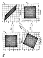
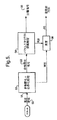
図1を参照すると、4つのグラフにおいて第2の信号に対して第1の信号がプロットされて示されている。源信号はラウドスピーカにより生成される単一音質のような正弦曲線である。各ポイントはそれぞれの時刻(サンプリング時間)における2つの信号値を表している。第1のグラフ10は、混合前の源信号を示している。第2のグラフ12は、混合後の同じ信号であるが、これらを逆混合する処理前を示しており、混合が伸張、ずれ、及び回転の複雑な組み合せに対応することを示している。第3のグラフ14は、非相関化及び正規化後であるが回転前の信号を示す。非相関化及び正規化は伸張とずれを排除する。第4のグラフ16は、これらをグラフ10のような元の形式に復元する回転後の信号を示す。グラフ14及び16は、回転の適用がずれ及び伸張を生成せず、従って非相関化及び正規化の影響を打ち消すことができないことを示している。
Referring to FIG. 1, the first signal is plotted against the second signal in four graphs. The source signal is a sinusoid such as a single sound quality produced by a loudspeaker. Each point represents two signal values at each time (sampling time). The
より数学的には、ベクトルxとして表される1つの集合の信号の相関行列Rは、
R=E((x−E(x))(x−E(x))H) ……(5)
として定義することができ、式中、E(x)はxの期待値であって、ある期間にわたるxの平均であり、上付き文字Hはエルミート共役を意味する。式(5)において、E(x)はxから減算されるが、これは以後続く全体処理における第1段階である。しかしながら、表記を簡単にするために、通常、信号はゼロ平均値を有すると仮定され、この仮定が以下において使用される。これは式(5)が、R=E(xxH)として簡略化されることを意味する。しかしながら、本発明を有効とするためには信号がゼロ平均値である必要はない。
More mathematically, the correlation matrix R of a set of signals, expressed as a vector x, is
R = E ((x-E (x)) (x-E (x)) H ) (5)
Where E (x) is the expected value of x and is the average of x over a period of time, and the superscript H means Hermitian conjugate. In equation (5), E (x) is subtracted from x, which is the first stage in the overall processing that follows. However, to simplify the notation, it is usually assumed that the signal has a zero mean value, and this assumption is used below. This means that equation (5) is simplified as R = E (xx H ). However, in order for the present invention to be effective, the signal need not be a zero average value.
混合信号に対して2オーダの独立性を与えるためには、相関行列Rに対してゼロに等しい非対角係数を持たせるようにする必要がある。これは正確な量の受信信号1が受信信号2から減算され、結果として得られる出力が受信信号1から確実に非相関化されることを意味する。これが他の全ての信号に対して繰り返されて、受信信号1で非相関化される出力の集合を生成し、次いでこれが出力1として定義される。次に、出力の残りの集合は、これらを使用してこの手順を繰り返すことによって互いに非相関化される。これは、信号xを下三角行列、すなわち対角線より上の全ての係数がゼロに等しい行列と事前乗算することによって非相関化信号x’を取得することに相当する。非相関化信号はx’で示され、次式で定義される相関行列R’を有する。
R’=E(x’x’H)=E(LxxHLH)=I ……(6)
In order to give 2 orders of independence to the mixed signal, it is necessary to give the correlation matrix R an off-diagonal coefficient equal to zero. This means that the correct amount of the received
R ′ = E (x′x ′ H ) = E (Lxx H L H ) = I (6)
ここで、正確な対角行列ではないが単位行列Iである新しい相関行列が示される。これは、状態に影響を与えることなく各信号とスカラー因子とを乗算することが可能であることに起因する。従って、全ての非対角要素がゼロに等しくその対角上の正の数を有する任意の相関行列は、各信号をその自己相関の平方根で除算することによって単位行列Iに変換することができる。これは上述の正規化プロセスであり、後のプロセスが確実に非相関段階の影響を相殺しないことが必要である。 Here, a new correlation matrix is shown which is not an exact diagonal matrix but is a unit matrix I. This is due to the fact that each signal can be multiplied by a scalar factor without affecting the state. Thus, any correlation matrix with all off-diagonal elements equal to zero and having a positive number on that diagonal can be converted to a unit matrix I by dividing each signal by the square root of its autocorrelation. . This is the normalization process described above, and it is necessary to ensure that later processes do not offset the effects of the decorrelation stage.
非相関化の後で信号を回転する。図1の14と16に示されるように、回転は結合確率密度関数のストレートエッジを座標系軸と位置合わせするように選択される。幾つかの異なる回転がこれを行い、これらは出力のオーダの置換及び/又は出力に−1を乗算することに相当する。これらの差は有意ではない。 Rotate the signal after decorrelation. The rotation is selected to align the straight edge of the joint probability density function with the coordinate system axis, as shown at 14 and 16 in FIG. Several different rotations do this, which corresponds to permuting the output order and / or multiplying the output by -1. These differences are not significant.
数学的にユニタリ行列は回転を表し、それぞれのエルミート共役と乗算されると単位行列を与える。非相関信号x’とユニタリ行列Uを事前乗算して信号x″を得ることは、2オーダの非相関段階に影響を与えない。これは期待値演算子の線形性を用いて以下のように表される。
R″=E(x″x″H)=E(Ux’x’HUH)=UE(x’x’H)UH=UIUH=UUH=I=R’ ……(7)
Mathematically the unitary matrix represents a rotation and gives a unit matrix when multiplied by the respective Hermite conjugate. Pre-multiplying the uncorrelated signal x ′ and the unitary matrix U to obtain the signal x ″ does not affect the two-order decorrelation stage. This uses the linearity of the expectation operator as follows: expressed.
R "= E (x" x "H) = E (Ux'x 'H U H) = UE (x'x' H) U H = UIU H = UU H = I = R '...... (7)
このようにUのユニタリ特性によって、2オーダ段階ではUの適用で変化しないままになる。 Thus, due to the unitary characteristics of U, the application of U remains unchanged in the 2-order stage.
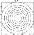
適正なUを見いだすことができない場合もある。これは2つの信号が互いにガウス分布を有する場合である。この特別な場合、2オーダの独立性は全体的な独立性であることを意味する。図2は2つの独立ガウス分布の結合確率密度関数の輪郭プロットであり、ここで輪郭線は、2つの信号の各々異なる値の結合確率密度関数値を示す。この関数は完全な回転対称を有するので、回転が適用されても変化しない。従って、回転はこの関数のあらゆる調整に影響を与えないので、回転を生じさせるのに使用されるデータに依性を導入することも排除することもない。 In some cases, the correct U cannot be found. This is the case when the two signals have a Gaussian distribution. In this special case, two-order independence means global independence. FIG. 2 is a contour plot of the joint probability density function of two independent Gaussian distributions, where the contour line shows the joint probability density function value of each different value of the two signals. This function has perfect rotational symmetry and does not change when rotation is applied. Thus, rotation does not affect any adjustment of this function, so it does not introduce or eliminate dependence on the data used to cause the rotation.
信号分布がガウス確率密度関数に近い程、適正な回転を見いだすのが困難になる。これは信号の調整が適正な場合に検出するのがより難しいためで、誤差がより大きくなる。 The closer the signal distribution is to the Gaussian probability density function, the more difficult it is to find the proper rotation. This is because it is more difficult to detect when the signal is properly adjusted, resulting in a larger error.
瞬時混合問題用のブラインド信号分離アルゴリズムでは、2つの別個のセンサに到達する信号ソースからの信号の時間サンプル間の相対伝播遅延を、一方のセンサによって受信された信号に適用されるサンプル位相シフトとして表すことができることが要求される。N個のセンサに対して、これはN−1個の位相シフトとなる。この条件が成立しない場合、信号ソースから各センサまでのチャネルは畳み込みとすることができ、瞬時アルゴリズムは機能しないことになる。 In the blind signal separation algorithm for the instantaneous mixing problem, the relative propagation delay between the time samples of the signal from the signal source reaching two separate sensors is taken as the sample phase shift applied to the signal received by one sensor. It is required that it can be represented. For N sensors, this is N-1 phase shifts. If this condition is not satisfied, the channel from the signal source to each sensor can be convoluted, and the instantaneous algorithm will not function.
次に、1チャネルの畳み込みとz変換を用いた解析を考察する。単一の信号及び単一の受信器構成において、ラウドスピーカの信号は、s(t)によって取得され示されたそれぞれの時間tによって索引付けられた一連の値から成る。ラウドスピーカの信号は、チャネルを通って別の一連の値x(t)を検出する受信器によって受信される。s(t)とx(t)との間のリンクは瞬時混合におけるような単純な乗算ではない可能性がある。代わりにx(t)は、s(t)のこれまでの値の幾つかの線形和から成るものとすることができる。これは畳み込みとして知られており、次式によって示される。
![]()
![]()
畳み込みは、係数による単純な乗算と比べてより複雑でより多くの代数を含む。しかしながら、以下のようなz変換を使用することによって乗算に対して畳み込みを低減することが可能である。s、x、及びhのz変換は、
s(z)=s(0)+s(1)z-1+s(2)z-2+s(3)z-3...
x(z)=x(0)+x(1)z-1+x(2)z-2+x(3)z-3...
h(z)=h(0)+h(1)z-1+h(2)z-2+...+h(p)z-p……(9)
Convolution is more complex and involves more algebra than simple multiplication by coefficients. However, it is possible to reduce the convolution for multiplication by using a z-transform as follows: The z-transform of s, x, and h is
s (z) = s (0) + s (1) z −1 + s (2) z −2 + s (3) z −3 . . .
x (z) = x (0) + x (1) z −1 + x (2) z −2 + x (3) z −3 . . .
h (z) = h (0) + h (1) z −1 + h (2) z −2 +. . . + H (p) z -p ...... (9)
式中、z-1は上述のように遅延演算子と呼ばれる。サンプル値の時系列として表された信号のz変換は、z-1の多項式である。z変換の形式が与えられると、その多項式係数は源信号を回復することができる。これらのz変換で形成すると、s×hの畳み込みは、式(5)に示されるように2つの多項式の積になり、すなわち以下の通りである。
x(z)=h(z)s(z) ……(10)
In the formula, z −1 is called a delay operator as described above. The z-transform of the signal expressed as a time series of sample values is a z −1 polynomial. Given the form of the z-transform, its polynomial coefficients can recover the source signal. Formed by these z-transforms, the s × h convolution is the product of two polynomials as shown in equation (5), ie:
x (z) = h (z) s (z) (10)
畳み込み混合は、式(3)のように瞬時混合を式(8)乃至(10)のより複雑な手法と組み合せることによって対処することができる。これは、複数のソースと畳み込みする介在チャネルを備えた複数の受信器に対応する。従って、2つの信号で2つの受信器の場合、受信信号に関して次式で表すことができる。
![]()
![]()
![]()
![]()
式(4)のベクトル行列の表記において、式(9)及び(10)のz変換表記を用いると、式(11)は次のように簡単に表すことができる。
x(z)=H(z)s(z) ……(12)
In the expression of the vector matrix of Expression (4), Expression (11) can be simply expressed as follows using the z-transform expression of Expressions (9) and (10).
x (z) = H (z) s (z) (12)
式中、s(z)はラウドスピーカ出力のz変換から形成された2×1係数ベクトルである。H(z)は2×2係数多項式混合行列であり、x(z)は受信信号のz変換から形成された2×1ベクトルである。更にまた、2つより多いラウドスピーカ及び/又は受信器が存在する場合、これに応じてs(z)、x(z)、及びH(z)のサイズが大きくなる。 Where s (z) is a 2 × 1 coefficient vector formed from the z-transform of the loudspeaker output. H (z) is a 2 × 2 coefficient polynomial mixing matrix, and x (z) is a 2 × 1 vector formed from the z-transform of the received signal. Furthermore, if there are more than two loudspeakers and / or receivers, the size of s (z), x (z), and H (z) increases accordingly.
H(z)は、信号の混合を示すことにより多項式混合行列と呼ばれ、この係数はz-1の多項式である。H(z)はまた、係数が行列であるz-1の多項式と見なすことができる。個々のラウドスピーカ/受信器チャネルのz変換を取ることによって、1回につき1つの係数が見いだされる。今後の利便性のために、多項式行列のオーダと次数をここで定義する。多項式行列のオーダは、行列内でz-1が累乗される最大の累乗である。多項式行列の次数は、該行列をフィルタとして実行するのに必要な遅延の最小数である。これは少なくとも常にオーダと同じ大きさであるが、これよりも優に大きな場合もある。 H (z) is referred to as a polynomial mixing matrix by indicating signal mixing, and this coefficient is a polynomial in z −1 . H (z) can also be viewed as a polynomial in z −1 whose coefficients are matrices. By taking the z-transform of the individual loudspeaker / receiver channels, one coefficient is found at a time. For future convenience, the order and order of the polynomial matrix are defined here. The order of the polynomial matrix is the largest power in the matrix where z -1 is raised. The order of the polynomial matrix is the minimum number of delays required to run the matrix as a filter. This is always at least as large as the order, but may be much larger than this.
正常な瞬時アルゴリズムのフレームワークにより、畳み込み逆混合アルゴリズムは2つの段階を有するべきであることが提示される。第1段階は2オーダの独立性を与えることになる。第2段階は、より高いオーダの独立性を与えると共に、2オーダを維持する。しかしながら、2オーダの独立性の測定は、時間遅延にわたって動作する必要がある。すなわち、2オーダの独立であるためには、信号の1つに任意の時間遅延が適用されたときに、2つの信号間の相関はゼロでなければならない。これは数学的に下記のように表すことができる。
R(d)=E(x(t)x(t−dH))=D(d)
∀d∈(…−2,−1,0,1,2…) ……(13)
ここで、∀d∈(…−2,−1,0,1,2…)は全ての正と負の全数の集合における遅延d(単位は連続する信号サンプルの時間間隔)の全ての値を意味し、D(d)は全てのdの値に対する対角行列(全ての非対角係数がゼロ)である。式(13)を以下のようにz変換形式にすることができる。
![]()
R (d) = E (x (t) x (t−d H )) = D (d)
∀d∈ (..., -2, -1, 0, 1, 2, ...) (13)
Here, ∀d∈ (..., −2, −1, 0, 1, 2. Meaning, D (d) is a diagonal matrix (all off-diagonal coefficients are zero) for all values of d. Equation (13) can be in z-transform form as follows:
![]()
2オーダの独立性を達成するために、多項式相関行列の全ての非対角項をゼロ多項式にする、すなわち全ての係数としてゼロを有するz-1の多項式にする必要がある。加えて、その対角上の行列の多項式関数は同一でなければならないので、相関行列は多項式×単位行列に等しい。すなわち、
非相関化を行うこと及び対角項を同一にすることは、1つのアルゴリズムによって行うことができる。このアルゴリズムは多チャネル格子フィルタを実行するものであって従来技術で多くの異なる変形形態があり、これらは二乗根の無い形式や演算子の異なるオーダリング(ordering)を含む。例えば、S.Haykin,「Adaptive Filter Theory」,Prentice Hall(1991年)を参照されたい。 Performing decorrelation and making the diagonal terms the same can be done by one algorithm. This algorithm implements a multi-channel lattice filter, and there are many different variations in the prior art, including forms without square roots and different ordering of operators. For example, S.M. See Haykin, “Adaptive Filter Theory”, Prentice Hall (1991).
多チャネル格子フィルタが、信号処理の当業者であれば選択することができる異なる収束及び安定特性を有するものとして知られているので、その説明は行わない。しかしながら、本明細書では便宜上、これらは全て容認できる程度には正常であり、且つ同じ答を導くと仮定する。 Since multi-channel grating filters are known to have different convergence and stability characteristics that can be selected by those skilled in the art of signal processing, they will not be described. However, for the sake of convenience herein, it is assumed that these are all acceptable to normal and lead to the same answer.
単位多項式は、その係数が1であるz0を除いて、z-1の全ての累乗に対してゼロの係数を有する多項式である。多チャネル格子フィルタは、多項式相関行列の対角項がこれらを全て単位多項式にすることによって同一になることを保証する。これは信号を白色化することである。 A unit polynomial is a polynomial with zero coefficients for all powers of z −1 , except for z 0 whose coefficient is 1. The multi-channel lattice filter ensures that the diagonal terms of the polynomial correlation matrix are identical by making them all unit polynomials. This is to whiten the signal.
信号x(z)の多項式相関行列は、上式(14)によって与えられる。多チャネル格子フィルタは、これらを変換して非相関化及び白色化された信号x’(z)の行列を得る。これらの信号はその相関行列が多項式単位行列である特性を有し、記号を用いて以下に示される。
![]()
![]()
多項式行列の空間に対するエルミート演算子の拡張は、パラ共役の選択肢である。この多項式行列はこれらのパラ共役と乗算したときに単位行列を与えるので、これはパラユニタリ行列を定義することになる。記号で表すと、
![]()
![]()
パラユニタリ行列H(z)をx’(z)に適用すると、非相関化及び白色化された信号の行列はx″(z)を生成し、次の式は2オーダの独立性が保たれることを示す。
同様にまた、2オーダの独立性の保存は、パラユニタリ行列の定義付け特性にすぐ続いていることが分かる。しかしながら、白色化は不可欠ではなく、必要とされる全ては、対角多項式相関行列が多項式因子×単位行列であることである。多項式因子は、式(17)の全ての要素と交換可能であり、そのため保存がなされる。このことは、畳み込み逆混合問題に対する実行可能な手法が、2オーダの独立性及び白色化を加えるために多チャネル格子フィルタを適用し、次いで4又はより高いオーダの独立性の測定値を最大化するパラユニタリ多項式行列を探索することであることを示している。 Similarly, it can be seen that the conservation of independence of the two orders immediately follows the defining properties of the paraunitary matrix. However, whitening is not essential and all that is required is that the diagonal polynomial correlation matrix is a polynomial factor × unit matrix. The polynomial factor is interchangeable with all elements of equation (17) and is therefore saved. This means that a feasible approach to the convolutional backmixing problem applies a multi-channel grid filter to add 2 orders of independence and whitening, and then maximizes 4 or higher order independence measurements. To search for a paraunitary polynomial matrix.
前述のようにVaidyanathanの引例は、全てのパラユニタリ行列の空間のパラメータ化を開示している。これはパラユニタリ行列z-1を段階毎に分解する。2チャネルの場合におけるパラメータ化が図3に示される。これは、隣接するブロックが全て同様の個々の遅延ブロックΛ(z)によって隔てられている、一連のN+1回転ブロックQ0、Q1、...QNを有する。上部信号チャネル20及び下部信号チャネル22は、全てのブロックを通過する。増幅器24はチャネル入力信号倍率因子αを示し、上部チャネル因子が正であり、下部チャネル因子が「α」の前に「+−」で表示されるように正又は負である。
As mentioned above, the Vaidyanathan reference discloses the parameterization of the space of all paraunitary matrices. This decomposes the paraunitary matrix z −1 step by step. The parameterization in the case of 2 channels is shown in FIG. This is a series of N + 1 rotation blocks Q 0 , Q 1 ,..., Where adjacent blocks are all separated by similar individual delay blocks Λ (z). . . With a Q N. The
回転ブロックQ0乃至QNの各々は、ギヴンス回転(米国特許第4,727,503号参照)を自ら実装する各々2×2のユニタリ行列を実行する。ギヴンス回転とは、単一の回転角θによってパラメータ化される回転である。第1の回転ブロックQ0において、下部チャネル22の信号はギヴンス回転パラメータs0及びc0と乗算され、上部チャネル20の信号はギヴンス回転パラメータの−s0及びc0と乗算され、s0及びc0はそれぞれ、ブロックQ0によって実行される回転角度θの正弦及び余弦である。各c0の積は、他のチャネルからのs0又は−s0の積と合計され、それぞれのチャネル20又は22に沿って次のブロックΛ(z)に伝えられる和を生成する。この次のブロックΛ(z)は、下部チャネル22の信号を上部チャネル20の信号に対して遅延させる。次に、この手順は、下部チャネル22において同等の介在遅延Λ(z)を有する、後続の回転ブロックQ1乃至QNで繰り返される。
Each of the rotating blocks Q 0 through Q N implements a 2 × 2 unitary matrix that implements itself a Givens rotation (see US Pat. No. 4,727,503). A Givens rotation is a rotation parameterized by a single rotation angle θ. In the first rotation block Q 0 , the
回転ブロックQ0乃至QN及び遅延Λ(z)は、これら自体がパラユニタリであり、従ってこれらの積もまたパラユニタリ行列である。Vaidyanathanは、任意の有限の次数Nのパラユニタリ行列がこの形式で表現できることを証明した。従って、スカラー因子は別として、任意の有限の次数のパラユニタリ行列は、次式によって表すことができる。
HN(z)=QN...Λ(z)Q1Λ(z)Q0 ……(18)
式中、Nはパラユニタリ行列の次数である。従って次数Nのパラユニタリ行列HN(z)は、図3の連結ステージによって示されるように、N+1個のギヴンス回転と、遅延の等しいN個の1チャネル遅延演算子との積である。
The rotating blocks Q 0 to Q N and the delay Λ (z) are themselves paraunitary, so their product is also a paraunitary matrix. Vaidanathan proved that any finite order N paraunitary matrix can be expressed in this form. Therefore, apart from scalar factors, any finite order paraunitary matrix can be expressed by the following equation.
H N (z) = Q N. . . Λ (z) Q 1 Λ (z) Q 0 (18)
Where N is the order of the paraunitary matrix. Thus, the order N paraunitary matrix H N (z) is the product of N + 1 Givens rotations and N equal one-channel delay operators, as shown by the concatenation stage of FIG.
しかしながら、Vaidyanathanパラメータ化を使用することは困難であり、その簡単な実施例をここに示す。ある非ガウス分布から得られた独立した等分布(iid)時系列の信号状況を考察する。白色化段階の考慮を排除するために、これらの信号はパラユニタリ混合行列によって混合されたものであることを前提とする。パラユニタリ混合行列の次数を1とし、以下のようなVaidyanathanパラメータ化を用いて形成されたと仮定する。
本発明は上記の困難な問題を克服することを目的とする。これは、Vaidyanathanパラメータ化と同様であるが、必ずしも1つのチャネルに限定されず、及び必ずしも同じものである必要はない可変の遅延を使用し、ゲインが殆どないか全くない場合に回転の適用を強制せず、任意の大きさのパラユニタリ行列を構築することができる。 The present invention aims to overcome the above difficult problems. This is similar to the Vaidanathan parameterization, but is not necessarily limited to one channel, and uses a variable delay that does not necessarily have to be the same, and applies rotation when there is little or no gain. A paraunitary matrix of any size can be constructed without forcing.
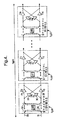
図4は、本発明によるN+1の基本パラユニタリ行列の積として構築されたパラユニタリ行列HN(z)を示す。基本パラユニタリ行列は、本発明のために新たに造られた表現であり、これは、信号に対して遅延集合の適用を表す多項式行列として定義され、この後に単一の直交変換(回転)が続く。図4においては、図3と同様に簡略化のために、上部チャネル30及び下部チャネル31で表される2つだけのチャネルの事例が示されている。波線のブロックの集合Vi(z)(i=0,1,…,N)の各々は、それぞれの遅延diに続いてギヴンス回転を実行するそれぞれの単一の基本パラユニタリ行列を表す。N+1のブロックVi(z)を用いて、パラユニタリ行列HN(z)を構成する。
FIG. 4 shows a paraunitary matrix H N (z) constructed as a product of N + 1 basic paraunitary matrices according to the present invention. The basic paraunitary matrix is a newly created representation for the present invention, which is defined as a polynomial matrix that represents the application of a delay set to a signal, followed by a single orthogonal transformation (rotation). . For the sake of simplicity, FIG. 4 shows an example of only two channels represented by an
ブロックV0(z)乃至VN(z)の各々は、これら自体がギヴンス回転を実行するそれぞれ2×2の基本パラユニタリ行列を実行する。第1のブロックV0(z)では、上部チャネル30及び下部チャネル31の信号は、経路指定を制御する4つの連動する単極双投スイッチ32の行列に入って通るか、或いは遅延セルZdoを介して通る。スイッチ32は全て、アップ又はダウン位置のいずれかにあり、ダウン時に上部チャネルの信号はZdoだけ遅延するが、下部チャネルの信号は遅延せず、アップ時にはこの逆になる。これによりチャネル30又は31のいずれかを他に対して遅延させることができる。
Each of the blocks V 0 (z) through V N (z) performs a 2 × 2 basic paraunitary matrix, each of which performs a Givens rotation. In the first block V 0 (z), the
スイッチ32を出ると、上部チャネル信号は、増幅器33と34のそれぞれにおいてギヴンス回転パラメータの−s0及びc0と乗算される。同様にスイッチ32を出ると、下部チャネル信号は、増幅器35及び36においてそれぞれギヴンス回転パラメータs0及びc0と乗算される。式中、s0及びc0はそれぞれ、ブロックV0(z)で実行される回転角度θの正弦及び余弦である。各c0の積は、他のチャネルからの信号を含むs0又は−s0の積と合計され、これがそれぞれのチャネル30及び31に沿って次のブロックV1(z)に伝えられる和を生成する。次いで、この遅延/回転手順は、後続のブロックV1(z)乃至VN(z)で繰り返される。この後のブロックは、遅延と回転が通常と異なること以外は第1のブロックV0(z)と同様に動作するため、これ以上の説明は行わない。適切な遅延及び回転を見つけるためのこの手順の実施については、理論的な議論に続いて後述する。
Upon exiting
基本パラユニタリ行列の観点からの本発明による完全なパラユニタリ行列のパラメータ化は、以下のように表すことができる。
本発明による逆混合の進行は、基本パラユニタリ行列をデータに全て適用した後に計算されるコスト関数を使用して改善が達成されたか否かを判定する。コスト関数は信号の独立性の測定値であり、その実施例は非ガウス的性質の4オーダの測定値であって、この4オーダの測定値が最小の時に最大となる。このようにして、このコスト関数の値が大きくなると信号間の依存性が排除されることになる。 The progress of backmixing according to the present invention determines whether an improvement has been achieved using a cost function calculated after applying all of the basic paraunitary matrices to the data. The cost function is a measurement of signal independence, an example of which is a four-order measurement of non-Gaussian nature, with a maximum when this four-order measurement is minimum. In this way, the dependency between signals is eliminated when the value of the cost function increases.
本発明の実施例で使用されるコスト関数は、ガウス分布からサンプリングされた分布の離脱の測定値であり、本明細書では、サンプリングされた分布は、観測された信号から生成された信号の確率密度関数の推定値である。中心極限定理は、混合信号がこれらのガウス的性質を増大させる傾向があり、信号の逆混合によりこれらの非ガウス的性質の測定値を増大させるべきであることを示している。従って、コスト関数は、部分的な逆混合だけが行われる場合は増大させるべきであり、これにより各連続する基本パラユニタリ行列の影響を試験することができるので有益である。これは、逆混合の最後の段階を除く全てに対して鈍感な幾つかの独立性の測定値とは対照的である。 The cost function used in an embodiment of the present invention is a measure of the divergence of a distribution sampled from a Gaussian distribution, where the sampled distribution is the probability of a signal generated from the observed signal. It is an estimate of the density function. The central limit theorem indicates that mixed signals tend to increase these Gaussian properties, and that the non-Gaussian property measurements should be increased by demixing the signals. Thus, the cost function should be increased if only partial backmixing is performed, which is beneficial because it allows the effect of each successive elementary paraunitary matrix to be tested. This is in contrast to some independent measurements that are insensitive to all but the last stage of backmixing.
このコスト関数は、連続する基本パラユニタリ行列にどの遅延範囲が最善の結果をもたらすかを見つけるために使用される。これは独立コスト関数(ICF)と呼ばれる。 This cost function is used to find which delay range gives the best results for successive elementary paraunitary matrices. This is called an independent cost function (ICF).
本発明のプロセスは信号を取り入れ、最初にこれらを多チャネル格子フィルタに通し、非相関及び白色化して2オーダの独立性を与える。次の段階は適切なパラユニタリ逆混合行列を見つけることである。この行列は、Vaidyanathanによって明らかにされたようにパラメータ化されないが、代わりに、逐次計算された基本パラユニタリ行列の点からパラメータ化される(式(20)参照)。導出後、各基本パラユニタリ行列を計算に使用される各信号に適用する。これにより、次のこのような行列の計算に好適な形式に信号が変換される。 The process of the present invention takes signals and first passes them through a multi-channel grating filter to decorrelate and whiten to give two orders of independence. The next step is to find a suitable paraunitary inverse mixing matrix. This matrix is not parameterized as revealed by Vaidyanathan, but instead is parameterized from the points of the fundamental paraunitary matrix computed sequentially (see equation (20)). After derivation, each basic paraunitary matrix is applied to each signal used in the calculation. As a result, the signal is converted into a format suitable for the calculation of the following matrix.
基本パラユニタリ行列を計算するために、実行可能な遅延集合が考慮される。最新の基本パラユニタリ行列は、信号に対して計算されたICFを最大化するものを選択し、この信号は、最新のものを含めてこれまで計算されたこうした全ての行列を適用することにより変換される。最新の基本パラユニタリ行列を識別するために、該行列の遅延及び回転を特定する必要がある。数えられる無限の様々な可能性のある遅延が存在するが、これ以外に数えられない別の回転のパラメータが存在する。現実的には、可算無限の遅延可能性が、考慮されるべき有限の数の様々な遅延にまで低減されることになる。 In order to compute the basic paraunitary matrix, a feasible delay set is considered. The latest basic paraunitary matrix selects the one that maximizes the ICF computed for the signal, and this signal is transformed by applying all such matrices computed so far, including the latest one. The In order to identify the latest basic paraunitary matrix, it is necessary to specify the delay and rotation of the matrix. There are an infinite variety of possible delays that can be counted, but there are other rotation parameters that cannot be counted. In reality, the countable infinite delay potential will be reduced to a finite number of different delays to be considered.
遅延の試行値が信号に適用されると、回転パラメータs0及びc0が選択される。これらのパラメータは、出力信号のICFを明確に最大化する手法を使用することによって選択することができる。しかしながら、従来技術の瞬時アルゴリズムを用いる方がより速く、これらのアルゴリズムは、混合された信号を瞬時的に逆混合するように設計されており、出力のICFをほぼ最大化するパラメータ値を生成するはずである。瞬時アルゴリズムの選択を考慮する最適値からかけ離れたICFが選択されると、ICFはそのアルゴリズムによってあまり改善される可能性はない。瞬時アルゴリズムと形式が同じICFを選択することによってこの問題が回避される。 When a delay trial value is applied to the signal, the rotation parameters s 0 and c 0 are selected. These parameters can be selected by using techniques that explicitly maximize the ICF of the output signal. However, it is faster to use prior art instantaneous algorithms, which are designed to instantaneously demix the mixed signal and generate parameter values that nearly maximize the output ICF. It should be. If an ICF far from the optimal value that takes into account the selection of the instantaneous algorithm is selected, the ICF is unlikely to be improved much by that algorithm. This problem is avoided by selecting an ICF that has the same format as the instantaneous algorithm.
従って、試用遅延の範囲を見て、各遅延において遅延及び回転を適用した後にICFを最大化した回転を付加することができる。これは、実行可能な基本パラユニタリ行列の集合を生成し、各々が、これを信号に適用して結果として得られる出力のICFを見つけることによって発見されたそれぞれのICFに関連付けられる。選択された基本パラユニタリ行列は、最適なICF出力を有するものである。この段階は、ICFにゲインが見られなくなるまで繰り返される。 Therefore, looking at the range of trial delays, it is possible to add a rotation that maximizes the ICF after applying the delay and rotation at each delay. This is associated with a respective ICF found by generating a set of executable basic paraunitary matrices, each of which is applied to the signal to find the resulting output ICF. The selected basic paraunitary matrix is the one with the optimal ICF output. This stage is repeated until no gain is seen in the ICF.
本発明のプロセスのこの段階は、各々が使用によって結果として得られる出力のICFの測定値を最大化するように選択される基本パラユニタリ行列の集合を連続して適用するものとして見ることができる。各基本パラユニタリ行列は、1つの回転を含む。このように、本発明のプロセスは、順次最適回転(SBR)アルゴリズムと呼ばれるアルゴリズムを実行する。このアルゴリズムは、パラユニタリ行列の基本パラユニタリ行列への分解、及びアルゴリズムの最後だけでなく各段階で有効に計算された測定値の使用を含む。これら2つのステップの組み合せは、アルゴリズムを順次実行可能な一連の同様な段階に分離する。 This stage of the process of the present invention can be viewed as successively applying a set of basic paraunitary matrices that are each selected to maximize the ICF measurement of the resulting output through use. Each basic paraunitary matrix contains one rotation. Thus, the process of the present invention performs an algorithm called a sequential optimal rotation (SBR) algorithm. This algorithm involves the decomposition of the paraunitary matrix into a basic paraunitary matrix and the use of measurements that are effectively calculated at each stage as well as at the end of the algorithm. The combination of these two steps separates the algorithm into a series of similar stages that can be executed sequentially.
次に、図5を参照すると、本発明のプロセスの一般的な態様のフロー図が示される。混合された信号50が、従来技術の多チャネル格子線形予測フィルタ52の入力51に供給され、該フィルタは信号を遅延の広範囲にわたって非相関化してこれを白色化する。フィルタ52は、従来技術で良く知られた種類のものであり、特に、S.Haykinによって、「Adaptive Filter Theory」,Prentice Hall(1991年)に記載されている。詳細には説明を行わない。これは2オーダの独立性を与えると共に、この独立性が後続のパラユニタリ行列の適用によって非相関化信号から確実に除去されることが無いようにする。このプロセスにおいて、フィルタ52は多項式非相関行列W(z)を導出する。フィルタ52によって生成された非相関信号53は、行列探索段階54に移り、ここで多項式パラユニタリ行列H(z)が導出され、非相関化信号に適用されて、4オーダの独立性を有する要求の分離信号55を生成する。また、行列探索段階54は、W(z)と共に乗算器56に移行する行列H(z)を出力する。乗算器56は、W(z)をH(z)と事前乗算して、混合信号50から分離信号55への変換を表す逆混合行列J(z)を与える。
Referring now to FIG. 5, a flow diagram of a general aspect of the process of the present invention is shown. The
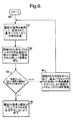
次に図6を参照すると、基本パラユニタリ行列の集合の積としてパラユニタリ多項式行列H(z)を生成するための、本発明の反復プロセスを示すフロー図が示される。各順次反復プロセスの最初において、導出されるパラユニタリ行列のそれぞれの最新値h(z)、即ち現時点までに計算された全ての基本パラユニタリ行列の積がある。また、h(z)に組み込まれたごく最近の計算された基本パラユニタリ行列を使用して導出された最新の信号の集合が存在し、h(z)は、最新の信号を取得するために元の入力混合信号(図5の50)を転化する変換を表し、これは、h(z)がH(z)になる点において、ICFを何ら改善しない別の基本パラユニタリ行列を適用するまで繰り返し改善される。 Referring now to FIG. 6, a flow diagram illustrating the iterative process of the present invention for generating a paraunitary polynomial matrix H (z) as a product of a set of basic paraunitary matrices is shown. At the beginning of each sequential iteration process, there is a product of each latest value h (z) of the derived paraunitary matrix, i.e. all the basic paraunitary matrices calculated so far. There is also a latest set of signals derived using the most recently computed basic paraunitary matrix built into h (z), where h (z) is the original signal to obtain the latest signal. Represents a transformation that transforms the input mixed signal (50 in FIG. 5), which iteratively improves until another basic paraunitary matrix that does not improve ICF at all is applied in that h (z) becomes H (z). Is done.
プロセスは60で始まり、ここで最初の最新信号は非相関化及び白色化された53における入力の源信号であり、パラユニタリ行列h(z)の最初の最新値は単位行列Iである。61において、最新信号を用いて最新の基本パラユニタリ行列を生成し、62において、この行列を最新信号に適用して新しい信号を生成する。63において、新しい信号は、これらの統計的な独立特性が改善されたかどうかを見るために試験され、こうした改善が得られていた場合は、64において最新の基本パラユニタリ行列を用いてh(z)を事前乗算し、導出されるパラユニタリ行列のごく最新の値を与え、新しい信号が最新の信号になる。次いで、h(z)の最新の値及び最新の信号を段階61に戻し、段階61、62、及び63の手順を繰り返す。
The process begins at 60, where the first latest signal is the input source signal at 53 which is decorrelated and whitened, and the first latest value of the paraunitary matrix h (z) is the identity matrix I. At 61, the latest basic paraunitary matrix is generated using the latest signal, and at 62, the matrix is applied to the latest signal to generate a new signal. At 63, the new signal is tested to see if these statistical independence properties have been improved, and if such improvement has been obtained, at 64 using the latest basic paraunitary matrix, h (z) And give the very latest value of the derived paraunitary matrix, and the new signal becomes the latest signal. The latest value of h (z) and the latest signal are then returned to step 61 and the procedure of
63において、最新の信号にわたって何の改善も得られなかったことを新しい信号が示す場合には、プロセスは解に収束したものと見なされ、65で終了する。h(z)の最新の値がH(z)として出力され、最新の信号が要求された分離信号として出力される。このように基本パラユニタリ行列を使用することにより、信号の分離とH(z)の取得の問題が幾つかの副次的な問題に分割される。 If at 63 the new signal indicates that no improvement has been obtained over the latest signal, the process is considered to have converged to the solution and ends at 65. The latest value of h (z) is output as H (z), and the latest signal is output as the requested separation signal. By using the basic paraunitary matrix in this way, the problem of signal separation and H (z) acquisition is divided into several secondary problems.
61において各基本パラユニタリ行列を探索する方法、及び63において新しい信号が最新の信号にわたって改善されたか否かを判定するための方法を次に説明する。前者の方法は非ガウス信号に依存するため、前述のように瞬時アルゴリズムを機能させることができる。後者の方法は、使用されている信号の独立性の測定値に依存する。正確で包括的な独立コスト関数は、サンプリングされた信号から計算することはできないが、独立性の種々の様々な部分的測定値を計算することはできる。良好な独立コスト関数がここで与えられる。これは次式で定義される信号の集合の4オーダの尖度項(kurtosis term)のκ(x1,x2,x3,x4)に基づく。
63において最新の信号と新しい信号とが、これらのICFを計算することによって比較され、2つのうちICFが高い信号の方がより優れているものとして認められる。 At 63, the latest signal and the new signal are compared by calculating their ICF, and the signal with the higher ICF out of the two is recognized as superior.
61において最新の基本パラユニタリ行列を取得するために、このような行列、遅延パラメータd、及び回転パラメータθを特徴付ける2つのパラメータを導出することが必要である。従って、パラユニタリ行列の識別は、(d,θ)の探索を軽減する。パラメータdはベクトルパラメータであり、2つより多い信号がある場合には、θはベクトルパラメータである可能性がある。しかしながら、この実施例では、信号が2つの場合だけ考慮されているのでθはベクトルではない。 In order to obtain the latest basic paraunitary matrix at 61, it is necessary to derive two parameters that characterize such a matrix, the delay parameter d, and the rotation parameter θ. Thus, the identification of the paraunitary matrix reduces the search for (d, θ). The parameter d is a vector parameter, and if there are more than two signals, θ may be a vector parameter. However, in this embodiment, θ is not a vector because only two signals are considered.
遅延パラメータdを探索するために、実現可能な値の集合Dが選択される。2信号の場合に好適な集合は以下の式(22)で示され、すなわちDは、
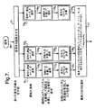
図7を参照すると、基本パラユニタリ行列を見つける方法を表すフロー図が示されている。Dにおける全ての遅延ベクトルδ1乃至δSに関して、それぞれの基本パラユニタリ行列が導出され、次にこれらの行列が生成する信号のICFを計算する。次いで、最適なICFに対応する基本パラユニタリ行列が選択されて使用される。図面では、2チャネルの場合において最新の信号のペアが70で入力される。71で信号はS回、すなわちDに遅延の値がある回数だけ再生される。2チャネルの場合、各レプリカは最新の信号のペアであり、各レプリカのペアは、Sが存在する、すなわちi=1乃至Sであるそれぞれの信号チャネル72iに入力される。3つのチャネル721、722、及び72Sが示され、他は73のような鎖線によって示されている。741乃至74Sでは、チャネル721乃至72Sの各々は、それぞれ遅延のベクトルδ1,...δSをDからそのレプリカに対して適用する。すなわち、これは他方に対するレプリカ内の最新の信号のペアの1つを遅延させ、i番目のチャネル72iは、i=1乃至Sであるi番目のレプリカに対して遅延ベクトルδiを適用する。チャネル721乃至72Sの各々において、相対的遅延は、70で入力された信号とは異なる信号のペアを生成するが、これらは前よりも決して独立してはいない。これらの信号を点毎の意味で可能な限り独立させるために、回転だけを用いることは、正に瞬時逆混合において実行されるものである。このように、前述のICAに対して、正常な従来技術の瞬時アルゴリズムのいずれかを適用することにより、適切な回転が得られる。これは良く知られており、説明は行わない。これは、751乃至75Sにおいて回転動作P1乃至PSとして実行され、それぞれ回転角θ1乃至θSを与える。 Referring to FIG. 7, a flow diagram representing a method for finding a basic paraunitary matrix is shown. For all delay vectors δ 1 to δ S in D, the respective basic paraunitary matrices are derived, and then the ICF of the signals generated by these matrices is calculated. The basic paraunitary matrix corresponding to the optimal ICF is then selected and used. In the figure, the latest signal pair is input at 70 in the case of two channels. At 71, the signal is reproduced S times, that is, as many times as there is a delay value in D. In the case of two channels, each replica is the latest signal pair, and each replica pair is input to each signal channel 72 i where S exists, i.e., i = 1 to S. Three channels 72 1 , 72 2 , and 72 S are shown, others are indicated by a dashed line like 73. 74 1 through 74 S , each of the channels 72 1 through 72 S has a respective delay vector δ 1 ,. . . Apply δ S from D to its replica. That is, this delays one of the latest signal pairs in the replica for the other, and the i th channel 72 i applies the delay vector δ i to the i th replica where i = 1 to S. . In each of the channels 72 1 to 72 S , the relative delay produces a different signal pair than the signal input at 70, but these are by no means independent. In order to make these signals as independent as possible in a point-by-point sense, using only rotation is exactly what is performed in instantaneous backmixing. Thus, an appropriate rotation can be obtained by applying any of the normal prior art instantaneous algorithms to the aforementioned ICA. This is well known and will not be explained. This is performed as rotating operations P 1 to P S at 75 1 to 75 S , giving rotation angles θ 1 to θ S , respectively.
各チャネル72iは、あたかもこれらのパラメータを実行する基本パラユニタリ行列が70で入力された信号に適用されたように、遅延ベクトルδi及び回転角θiから成る関連するパラメータを有し、更に、入力信号に適用されたときに、この行列は遅延要素δiの関連値に対してできる限り独立し得る出力信号を生成する回転をもたらす。従って、各チャネル72iの最初の2つの要素74iと75iは組み合せ状態で、それぞれのパラメータの集合(d,θ)=(di,θ1)を用いて基本パラユニタリ行列をシミュレートする。
Each channel 72 i has associated parameters consisting of a delay vector δ i and a rotation angle θ i as if a basic paraunitary matrix implementing these parameters was applied to the signal input at 70, and When applied to the input signal, this matrix provides a rotation that produces an output signal that can be as independent as possible with respect to the associated value of the delay element δi. Therefore, the first two
次の段階は、チャネル721乃至72Sのいずれが独立性を最大に改善する基本パラユニタリ行列をシミュレートするかを決定することである。これは761乃至76Sで実行され、ここでステージ751乃至75Sからの信号出力のICFがそれぞれ計算される。これらのICFは、77で互いに比較され、最大のICFを生成するどのチャネルでも独立性を最大に改善し、最善の基本パラユニタリ行列をシミュレートする。この行列は、図6の61で使用するために、図7に示されたプロセスの出力として選択される。
The next step is to determine which of the channels 72 1 to 72 S simulates the basic paraunitary matrix that improves the independence to the maximum. This is performed at 76 1 to 76 S , where the ICF of the signal output from
どちらのチャネルが最大のICFを生成するかを選択することは、実際のところ必須事項ではなく、この値に比較的近い値を与える別のチャネルが許容可能である。また、パラメータの1つにとってより好都合な値、例えばより短い遅延を与えるように選択される可能性がある。しかしながら、最大のICFに十分に近い値を与えないチャネルが選択された場合、後続の反復で状況を修正することが不可能になる可能性があるので、信号分離のプロセスは失敗する恐れがある。それ故に、ICFを与えるか、又は遅延及び回転のパラメータの範囲にわたり取得可能なこれらの最大値の少なくとも顕著な部分に対する独立性を改善するチャネルを選択する必要がある。 Choosing which channel produces the largest ICF is not actually a requirement, and another channel giving a value relatively close to this value is acceptable. It may also be selected to give a more convenient value for one of the parameters, for example a shorter delay. However, if a channel is chosen that does not give a value close enough to the maximum ICF, the signal separation process may fail because it may be impossible to correct the situation in subsequent iterations. . Therefore, there is a need to choose a channel that provides ICF or improves the independence of at least a significant portion of these maximum values obtainable over a range of delay and rotation parameters.
本発明の上述の実施形態は、2チャネルの場合、すなわち2つの信号ソース、2つの受信器、及び各信号ソースから受信器までの2つの経路に関連するものであった。チャネルが2つより多い場合は別の処理が必要である。しかしながら、本発明の手順はおおまかには同じであり、すなわち2オーダの独立性を達成するために信号を処理し、続いてこれらを分離するためにパラユニタリ行列を探索し、行列は連続する基本パラユニタリ行列の積であり、その各々の行列が入力信号への適用によっても得られる出力の独立性の測定値を最大化する。 The above-described embodiment of the present invention has been associated with the case of two channels: two signal sources, two receivers, and two paths from each signal source to the receiver. If there are more than two channels, separate processing is required. However, the procedure of the present invention is roughly the same, i.e., processing the signals to achieve two orders of independence, and then searching the paraunitary matrix to separate them, the matrix is a continuous basic paraunitary. Matrix product, each of which maximizes the output independence measurement obtained by application to the input signal.
本発明を2つより多いチャネルに拡大する方法は幾つかある。1つは上述の実施形態の単純な直接拡張である。他は、幾つかの従来技術のアルゴリズムの方法論の使用、すなわち信号ペアの使用、ペアの独立性を与える試み、及び全ての信号ペアのあるオーダの掃き出しである。 There are several ways to extend the invention to more than two channels. One is a simple direct extension of the embodiment described above. The other is the use of several prior art algorithm methodologies, ie, the use of signal pairs, attempts to provide pair independence, and sweeping of certain orders of all signal pairs.
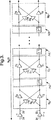
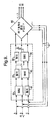
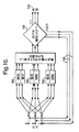
図8は、前述のVaidyanathanの従来技術によって与えられた多チャネル(すなわち3つ又はそれ以上のチャネル)の場合における次数Nのパラユニタリ行列の分解を示す。図3の2チャネルの場合と非常に類似している。違いは、基本的に2チャネル演算子であるギヴンス回転が、一度に全てのチャネルで動作する、より一般的な回転と置き換えられたことである。これは数学的に以下のように表すことができる。
HN(z)=RN...Λ(z)R1Λ(z)R0 ……(23)
式中、前と同様に、Λ(z)は最下位のチャネルの連続する単位遅延を表す行列であり、Ri(i=0からN)はi番目の回転を表す。nチャネルの場合、各回転は、n(nー1)/2個のパラメータを有し、2チャネルの場合に使用されたギヴンス回転においてn=2のときパラメータは1個に減少する。
FIG. 8 shows the decomposition of the order N paraunitary matrix in the case of multi-channels (ie, three or more channels) given by the prior art of Vaidyanathan. It is very similar to the two channel case of FIG. The difference is that the Givens rotation, which is basically a two-channel operator, has been replaced with a more general rotation that operates on all channels at once. This can be expressed mathematically as:
H N (z) = R N. . . Λ (z) R 1 Λ (z) R 0 (23)
In the equation, as before, Λ (z) is a matrix representing the continuous unit delay of the lowest channel, and Ri (i = 0 to N) represents the i-th rotation. In the case of n channels, each rotation has n (n−1) / 2 parameters, and in the Givens rotation used in the case of 2 channels, the parameter decreases to 1 when n = 2.
式(23)のパラメータ化は、図3に関連して説明した2チャネルの場合と同様の問題を包含する。ここでも同様に、問題に対処するために使用される手順は、パラユニタリ行列の基本パラユニタリ行列への分解であり、基本パラユニタリ行列は、分解を考慮して最後の回転以外の全ての回転を制約することによって見つけられる。最後の回転は制約を受けないが、他は全て制約されていずれも入力を不変のままにするか、又はチャネルの順序を順序付けるので、別のチャネルが後続の遅延を受信する。従って、最後の回転以外の全ての回転は順列であるように制約される。基本パラユニタリ行列は従って以下のように表すことができる。
Vd,θ(z)=RθΛ(z)...P1Λ(z)P0=RθDd(z) ……(24)
The parameterization of equation (23) involves the same problems as the two-channel case described in connection with FIG. Again, the procedure used to address the problem is the decomposition of the paraunitary matrix into a basic paraunitary matrix, which constrains all rotations except the last one to account for the decomposition. Can be found by The last rotation is unconstrained, but all others are constrained, either leaving the input unchanged or ordering the order of the channels so that another channel receives the subsequent delay. Thus, all rotations other than the last rotation are constrained to be permutations. The basic paraunitary matrix can thus be expressed as:
V d, θ (z) = R θ Λ (z). . . P 1 Λ (z) P 0 = R θ D d (z) (24)
式中、Piは順列行列であり、Rθはn(n−1)/2の回転角度θのベクトルによってパラメータ化された回転行列である。全ての順列行列と遅延行列の組み合せはDdによって表され、遅延行列と呼ばれる。その添え字dは長さnのベクトルであり、そのn要素はそれぞれのチャネルに適用された遅延である。 Where P i is a permutation matrix and R θ is a rotation matrix parameterized by a vector of n (n−1) / 2 rotation angles θ. All permutation and delay matrix combinations are represented by D d and are called delay matrices. The subscript d is a vector of length n, and the n element is the delay applied to each channel.
式(24)は、基本パラユニタリ行列の拡張形式を示す。第1に、全てのチャネルに適用されている異なる遅延から成る遅延行列が適用される。第2に、回転が適用される。前と同様に、信号を混合する1つの動作しか含まないので、これは基本的な構成ブロックにとって良好な選択である。しかしながら、この形式はパラメータ化が可能であり、そのパラメータはベクトルdとθである。これは、パラユニタリ行列の基本パラユニタリ行列への分解を以下のように表すことができることを意味する。
![]()
![]()
この拡張を見つけるための方法論は、2チャネルの場合と殆ど同じである。これは、単に、Dの選択、基本パラユニタリ行列の第1のステージを形成するための遅延集合又は可能性がある遅延集合の修正だけを必要とする。2チャネルの場合、Dの要素は、1つのチャネルだけに適用された遅延として取り扱われた。更に一般的な場合では、遅延は1つより多いチャネルで可能になる。2チャネルの場合には可算の無限の可能性があるので、Dを形成するためにかなりの有限の集合を選択する必要がある。 The methodology for finding this extension is almost the same as in the 2-channel case. This simply requires selection of D, a delay set to form the first stage of the basic paraunitary matrix, or a possible delay set modification. In the case of two channels, the element of D was treated as a delay applied to only one channel. In the more general case, delay is possible with more than one channel. Since there are countless infinite possibilities in the case of two channels, it is necessary to choose a fairly finite set to form D.
Dの要素の数は、その中の遅延の数に対してlで表される上限を設定することによって定めることができる。従ってDは、nチャネルの間でl個の遅延までの割り当てが可能な全ての方法で構成することが可能である。同一の遅延を全てのチャネルに対して同時に適用することは、遅延を全く適用しないことと同等であるため、Dの全ての要素は、遅延のない少なくとも1つのチャネルを有する必要がある。Dの中の要素の数は、nとlが増加するにつれて非常に迅速に増加することができる。前述のように、Dに対するこの方法は単なる堅実なオプションの選択である。他の可能性は存在するが、通常は有効性を確保するためにより一層の正当化が必要である。Dの定められた大きさに対してより高いlの許可を宣言することによって、幾つかの選択(1つのチャネルだけに遅延の適用を認めるなど)を正当化することが可能である。従って、小さな遅延のより複雑な組み合せの実行を認めないコストで、より長い遅延を考慮するアルゴリズムが可能となる。 The number of elements of D can be determined by setting an upper limit represented by l for the number of delays therein. Thus, D can be configured in any way that allows allocation of up to l delays among n channels. Since applying the same delay to all channels simultaneously is equivalent to applying no delay at all, all elements of D need to have at least one channel with no delay. The number of elements in D can increase very quickly as n and l increase. As mentioned above, this method for D is just a solid option choice. There are other possibilities, but usually more justification is needed to ensure effectiveness. By declaring a higher l grant for a defined size of D, it is possible to justify some choices (such as allowing only one channel to apply delay). Thus, an algorithm that allows for longer delays is possible at a cost that does not allow the execution of more complex combinations of small delays.
しかしながらこれ定義され、Dが決定されると、本発明のプロセスは、前述の実施形態の2チャネルの場合と同様に多チャネルの場合で進めることができる。2つの相違点があり、すなわち、第1に、図7の2要素遅延のベクトルδiは、n要素を有する遅延ベクトル(遅延集合Dの要素)で置き換えられ、ここでnはチャネルの数である。これにより、アルゴリズムが信号にDの要素を適用することが可能となる。第2に、ステージ751乃至75iで既知の瞬時アルゴリズムによって計算された回転は、ここではnチャネルの回転である。これらは、n(n−1)/2の2チャネルの回転を引き続き適用することによって取得することができるので、n(n−1)/2の角度パラメータによってパラメータ化することができる。前述の従来技術の瞬時アルゴリズムは、最新の信号と、これらを生成する回転行列を提供するので、そのプロセスはこれ以上説明しない。
However, once this is defined and D is determined, the process of the present invention can proceed in the multi-channel case as in the two-channel case of the previous embodiment. There are two differences: first, the two-element delay vector δ i in FIG. 7 is replaced by a delay vector having n elements (elements of delay set D), where n is the number of channels. is there. This allows the algorithm to apply elements of D to the signal. Secondly, the rotation calculated by the known instantaneous algorithm at
多チャネルの場合に対するこの手法は、遅延集合Dの大きさに問題を生じる可能性がある。これは、Dの各要素がベクトルであり、各要素に対して全体のn×nの瞬時アルゴリズムを実行する必要があることによる。遅延集合の上限lが増えるにつれて、このことは支配的な時間的制約となって処理を遅らせる。いわゆる「掃出し」アルゴリズムが従来技術で開発され、瞬時アルゴリズムの場合や、特異値分解アルゴリズムのような他のアルゴリズムにおける同様の問題を軽減しようとする試みがなされている。 This approach for the multi-channel case can cause problems with the size of the delay set D. This is because each element of D is a vector and the entire n × n instantaneous algorithm needs to be executed for each element. As the upper limit l of the delay set increases, this becomes a dominant time constraint and delays processing. So-called “sweep” algorithms have been developed in the prior art and attempts have been made to mitigate similar problems in the case of instantaneous algorithms and other algorithms such as the singular value decomposition algorithm.
「Independent Component Analysis,A new Concept?」,Signal Processing 36,pp287−314(1994年)で、P.Comonが、極めてゆるやかな条件下では、ペアの独立性を与えることは全体の独立性を与えることと同等であることを示した。残念なことに、任意の2つの信号に対してペアの独立性を与えるときに、他の信号のペアの独立性が影響を受けることになる。それにも関わらず、異なる信号の組み合せにより循環してペアの独立性を与えると、利用可能な全ての信号ペアを通して繰り返される掃き出しがあることを条件として、良好な信号の分離をもたらすことが示された。BLISSアルゴリズム、JADEアルゴリズム、及び前述の他のアルゴリズムは、ユニタリ回転行列を見つけるためにこの手法を使用する。これらは2つの信号を互いにペア独立にする際にのみ機能する。 “Independent Component Analysis, A new Concept?”, Signal Processing 36, pp 287-314 (1994). Comon showed that under very mild conditions, giving pair independence is equivalent to giving overall independence. Unfortunately, when providing pair independence for any two signals, the independence of other signal pairs will be affected. Nonetheless, cycling through different signal combinations to give pair independence has been shown to provide good signal separation, provided that there is a repeated sweep through all available signal pairs. It was. The BLISS algorithm, JADE algorithm, and other algorithms described above use this approach to find unitary rotation matrices. They only work when the two signals are pair-independent of each other.
BLISSアルゴリズムと同じ手法に従う基本パラユニタリ行列アルゴリズムを見つけるための本発明の手順は、掃き出しプロセスと呼ばれる。これは、掃き出しにおいて機能する利用可能な全ての信号ペアの組み合せの事前に決定された順序を有する。各信号ペアは、本発明の第1の実施形態の2チャネルプロセスを使用して処理される。残りの信号は、時間内に調整され(遅延され)るので、処理されている信号ペアとして適用された少なくともほぼ同じ遅延を有する。掃き出しの終わりに、本発明の上述の実施形態から同一の終端条件を適用して、別の掃き出しを実行する必要があるかどうか、又は有意な改善がこれ以上得られないかどうかを判定することができる。 The procedure of the present invention for finding a basic paraunitary matrix algorithm that follows the same approach as the BLISS algorithm is called the sweep-out process. This has a predetermined order of combinations of all available signal pairs that function in sweeping. Each signal pair is processed using the two-channel process of the first embodiment of the present invention. The remaining signals are adjusted (delayed) in time so that they have at least about the same delay applied as the signal pair being processed. At the end of the sweep, apply the same termination condition from the above embodiment of the present invention to determine if another sweep needs to be performed or if no further significant improvement is obtained Can do.
図9は3つの信号A、B、及びCに対する手順を示す。上述のように、本発明のプロセスは、順次最適回転すなわちSBRアルゴリズムを実行する。図面において、「SBR2」は、上述の実施形態のような2チャネルの場合に対するSBRアルゴリズムの適用を示す。 FIG. 9 shows the procedure for three signals A, B and C. As mentioned above, the process of the present invention performs a sequential optimal rotation or SBR algorithm. In the drawing, “SBR2” indicates application of the SBR algorithm to the case of two channels as in the above-described embodiment.
最初のフェーズにおいて、信号AとBは、90においてSBR2により処理され、91において信号Cは、90からの出力と実質的に同期して時間内に調整される。91における時間調整は、90において決定された多項式行列の半分のオーダだけCを遅延することによって実行される。すなわち、どのチャネルにその又は(場合によっては)各遅延があるかに関係なく、Cは、AとBの処理で適用された遅延の総合計の半分だけ時間内で遅延される。Cのこのような調整は必須ではないが、満足できる結果が得られることが分かっている。信号A、B、及びCは、使用されないときに保存されたディジタルデータのサンプルの系列であるので、処理の遅延が90においてSBR2を実行できるようにする必要はない。A又はBに対する「遅延」Cは単に、後続の処理ステージに対する一連の入力におけるサンプル数の変更を意味する。 In the first phase, signals A and B are processed at 90 by SBR2, and at 91, signal C is adjusted in time substantially synchronously with the output from 90. The time adjustment at 91 is performed by delaying C by the order of half the polynomial matrix determined at 90. That is, C is delayed in time by half the sum of the delays applied in the A and B processing, regardless of which channel has that or (possibly) each delay. Such adjustment of C is not essential, but it has been found that satisfactory results are obtained. Since signals A, B, and C are sequences of digital data samples that are stored when not in use, it is not necessary to allow SBR2 to be performed at a processing delay of 90. A “delay” C for A or B simply means a change in the number of samples in a series of inputs for subsequent processing stages.
ステージ90及び91で組み合せて、少なくとも1つの基本パラユニタリ行列を3つの信号全てに適用し、このような行列は、場合によっては、3つのチャネルをカバーするように90において生成された各2つのチャネルの基本パラユニタリ行列を拡張することによって生成される。その各行列は信号AとBに回転と遅延を適用するが、信号Cには回転なしで遅延を適用する。90において1つより多い基本パラユニタリ行列が求められると、信号Cに適用された全ての遅延は、91においてCに適用された合計の遅延に加算しなければならない。 In combination at stages 90 and 91, at least one elementary paraunitary matrix is applied to all three signals, such matrix possibly in each two channels generated at 90 to cover three channels. Generated by extending the basic paraunitary matrix. Each matrix applies rotation and delay to signals A and B, but applies delay to signal C without rotation. When more than one elementary paraunitary matrix is determined at 90, all delays applied to signal C must be added to the total delay applied to C at 91.
第2のフェーズにおいて、信号B(90における処理の後)と信号C(91における遅延の後)は、92でSBR2を使用して処理され、信号A(90における処理の後)は、93において時間内で92からの出力を使用して調整される。第3のフェーズでは、信号A(93における調整の後)と信号C(92における処理の後)は、94においてSBR2を使用して処理され、信号B(92における処理の後)は、94からの出力を使用して時間内で調整される。 In the second phase, signal B (after processing at 90) and signal C (after delay at 91) are processed at 92 using SBR2, and signal A (after processing at 90) is processed at 93. Adjusted using output from 92 in time. In the third phase, signal A (after adjustment at 93) and signal C (after processing at 92) are processed using SBR2 at 94, and signal B (after processing at 92) is Will be adjusted in time using the output of.
次の段階は、96において、信号がプロセスの終了に値するほど十分独立するようになったかどうか、又は、継続する必要があるかどうかを決定し、上述のように、この終端条件は、信号のICFが有意に改善されなかった場合に満足され、この場合処理は終了する。そうでない場合は、90、92、及び94の各々で決定されたそれぞれの基本パラユニタリ行列を用いてこれらに先行する保存された積を事前乗算して、最新の結果として得られた積をこれまで保存されたものと置き換える。次いで、SRB2の94と配列95からの最新の信号は、繰り返されるようにする手順のためのフィードバックループ97を介して90と91にフィードバックされる。
The next step determines at 96 whether the signal has become sufficiently independent to deserve the end of the process, or whether it needs to continue, and as described above, this termination condition is Satisfied if the ICF was not significantly improved, the process ends. Otherwise, pre-multiply the stored products preceding them using the respective basic paraunitary matrices determined at each of 90, 92, and 94 to obtain the latest resulting product so far. Replace with saved one. The latest signals from
この実施形態において、1つ又はそれ以上の2チャネルの基本パラユニタリ行列を、要素90乃至97のループを周る各循環に対してSBR2の段階における90、92、及び94に適用することができる。SBR2アルゴリズムにおける終端条件に合致するのに必要とされる数まで、この段階で望まれるできるだけ多くの基本パラユニタリ行列を適用することが可能である。91、93、及び95における信号調整の必要性が低減されるので、段階90、92、及び94において、1つだけの基本パラユニタリ行列を適用するのが望ましく、これは、SBR2プロセスにおける早期の回転が後からの同等の回転よりも多くの性能ゲインを与える傾向があるので、より重要な回転を最初に適用するといった原理を用いる。
In this embodiment, one or more two-channel elementary paraunitary matrices can be applied to 90, 92, and 94 in the SBR2 stage for each cycle around the loop of elements 90-97. It is possible to apply as many basic paraunitary matrices as desired at this stage, up to the number required to meet the termination conditions in the SBR2 algorithm. Since the need for signal conditioning at 91, 93, and 95 is reduced, it is desirable to apply only one basic paraunitary matrix at
固定された順序で信号ペアを動作させるのではなく、ICFの最大限の増加につながるペアを最初に動作させる場合には、別の手法を提示することができる。この手法はまた、ペアに対して動作するがペアの順序は固定ではない。代わりに、全ての可能性のあるペアを考慮に入れ、ICFの最大限の改善につながるものを受け入れる。これは可能性のある信号ペアを全て探索するので、これは探索プロセスとして知られている。図10は、3つの信号A、B、及びCに対する手順を示す。信号はn(nー1)/2回再現される。ここで、nは信号の数であり、本発明の実施例ではn=3で、同時に信号のレプリカが3つあることを意味する。最初のフェーズにおいて、100で3つの信号A、B、及びCの第1のレプリカを使用して、信号A及びBがSBR2を使用して処理され、信号Cがこのように生成された出力を使用して時間内で調整される。ここでまた、2つの信号チャネルに対するSBR2の適用によって生成された、1つの(又は場合によっては各)2チャネルの基本パラユニタリ行列を、その又は各残りの信号Cを遅延させる(しかし回転させない)nチャネルの基本パラユニタリ行列まで拡張し、SBR2で処理された信号AとBを使用して時間調整を維持する。 Instead of operating signal pairs in a fixed order, another approach can be presented when operating pairs that lead to the greatest increase in ICF first. This approach also works for pairs, but the order of the pairs is not fixed. Instead, it takes into account all possible pairs and accepts that lead to the greatest improvement in ICF. This is known as the search process because it searches for all possible signal pairs. FIG. 10 shows the procedure for three signals A, B and C. The signal is reproduced n (n-1) / 2 times. Here, n is the number of signals. In the embodiment of the present invention, n = 3, which means that there are three signal replicas at the same time. In the first phase, signals A and B are processed using SBR2 using a first replica of three signals A, B, and C at 100 and signal C is generated in this way. Use and adjust in time. Again, one (or possibly each) two-channel basic paraunitary matrix generated by application of SBR2 to two signal channels delays (but does not rotate) its or each remaining signal C n Extend to the basic paraunitary matrix of the channel and maintain the time alignment using signals A and B processed in SBR2.
第2のレプリカにおいて、101で信号AとCをSBR2を使用して処理し、信号Bは出力によって調整される。第3のレプリカにおいて、102で信号BとCを94におけるSBR2を使用して処理し、信号Aは出力によって調整される。103で、3つの出力信号グループのICFが求められ、最大のICFを有するグループが選択され、このICFがこのステージに対する入力信号にわたって改善を示す場合は、その動作が受け入れられる。 In the second replica, signals A and C are processed at 101 using SBR2, and signal B is adjusted by the output. In the third replica, signals B and C are processed at 102 using SBR2 at 94, and signal A is adjusted by the output. At 103, the ICFs of the three output signal groups are determined, and the group with the largest ICF is selected, and if this ICF shows improvement over the input signal for this stage, the operation is accepted.
上述のように、全ての信号のICFが改善された場合、処理は新たな最新の信号で継続し、新たな最新の行列がループ104を介して100、101、及び102にフィードバックされる。顕著な改善がない場合、処理は終了し、105において最新の信号とパラユニタリ行列が出力される。
As described above, if the ICF of all signals is improved, processing continues with the new latest signal, and the new latest matrix is fed back to 100, 101, and 102 via the
また、SBR2の段階100、101、及び102は、一連の基本パラユニタリ行列を改善が得られなくなるまで計算する完全なSBR2プロセスの適用か、又は単なる1つの基本パラユニタリ行列の探索から構成することができる。後者の場合は、完全なSBRの制約されたものと同等であり、すなわち、時間調整を無視すると、遅延は1つのチャネルの遅延だけに制約され、回転は遅延のチャネルと互いに対する回転の適用だけに制約される。これは遅延集合の大きさを小さくし、従って、基本パラユニタリ行列の計算速度を向上させる。 Also, SBR2 stages 100, 101, and 102 can consist of applying a complete SBR2 process that computes a series of basic paraunitary matrices until no improvement is obtained, or just searching for one basic paraunitary matrix. . The latter case is equivalent to a full SBR constrained, ie, ignoring time adjustment, the delay is constrained to only one channel delay, and the rotation is only the application of the rotation to the delay channel and each other Constrained by This reduces the size of the delay set and thus improves the computation speed of the basic paraunitary matrix.
2つより多いセンサを含む混合問題を取り扱うときに、全てのアルゴリズムは、センサが存在するよりも少ない信号が混合中に存在するという可能性に対処しなければならない。これは、存在する信号の数を検出し、高いオーダの独立性を導入する段階において処理すべきチャネル数を減少させることができる、2オーダの独立性が確立される段階で対処される。これは、多チャネル最小二乗格子予測アルゴリズム又はフィルタの各時間ステージから生成されたチャネルを見つけることによって行われた。1つ又はそれ以上のこれらのチャネルの出力が他より相当に低い場合、これは「ノイズチャネル」と呼ばれ、検討の対象から除外される。これは、多チャネル最小二乗格子予測アルゴリズムが適用されると、出力チャネルの数はその入力信号の数に等しいことを意味するはずである。 When dealing with mixing problems involving more than two sensors, all algorithms must deal with the possibility that fewer signals will be present during mixing than there are sensors. This is addressed at the stage where two-order independence is established, which can detect the number of signals present and reduce the number of channels to be processed in the stage of introducing high order independence. This was done by finding the channel generated from each time stage of the multi-channel least squares grid prediction algorithm or filter. If the power of one or more of these channels is significantly lower than the others, this is called a “noise channel” and is excluded from consideration. This should mean that when a multi-channel least squares grid prediction algorithm is applied, the number of output channels is equal to the number of its input signals.
上記説明で与えられた式及び手順は、明らかに適切な搬送媒体に記録され、従来のコンピュータシステム上で実行されるプログラム命令を備えた適切なコンピュータプログラムによって実行することができる。搬送媒体は、メモリ、フロッピー(登録商標)又はコンパクト又は光学ディスク、或いはハードウエア書き込み可能媒体、若しくは電気信号でもよい。このようなプログラムは、よく知られたコンピュータ手続きを含むので、熟練したプログラマーにとっては簡単であり、上述の説明から本発明に影響することなく実施することができる。 The equations and procedures given in the above description can be executed by a suitable computer program with program instructions clearly recorded on a suitable carrier medium and executed on a conventional computer system. The carrier medium may be a memory, floppy or compact or optical disk, a hardware writable medium, or an electrical signal. Such a program includes well-known computer procedures and is therefore easy for a skilled programmer and can be implemented without affecting the present invention from the above description.
上述の本発明の式及び手順は、異なる混合ケースにおいて幾つかの形式のシミュレート信号の逆混合のために正常に使用された。正常に逆混合された信号は、通信において使用されるような、独立識別分布(i.i.d)信号、フィルタ処理されたi.i.d信号、及び二相変位変調(BPSK)信号を含む。これらは、パラユニタリである混合行列の場合と、既知の次数のランダム多項式行列である混合行列の更に一般的な場合に分離された。 The above-described equations and procedures of the present invention have been successfully used for backmixing several types of simulated signals in different mixing cases. A normally demixed signal is an independent discriminant distribution (iid) signal, filtered i.d. i. d signal and a two-phase displacement modulation (BPSK) signal. These were separated into the case of a mixing matrix that is paraunitary and the more general case of a mixing matrix that is a random polynomial matrix of known order.
例えば、2つのBPSK信号を逆混合する場合、本発明のSBRアルゴリズムは、信号対雑音比が10dBで、ビット誤り率(BER)が0.3%より小さいこれらの信号を分離した。これらの信号は、1%を超えるBERを達成するだけの従来技術の手法で混合された。ここで関連する従来技術は、P.Comon,E. Moreau,L.Rotaの「Blind Separation of Convolutive Mixtures,AContrase−based Joint Diagonalisation Approach」,ICA2001 San Diego(2001年12月)である。 For example, when two BPSK signals are backmixed, the SBR algorithm of the present invention separated those signals with a signal to noise ratio of 10 dB and a bit error rate (BER) of less than 0.3%. These signals were mixed in a prior art manner that only achieved a BER greater than 1%. Related prior art here is P.I. Comon, E.M. Moreau, L .; Rota's "Blind Separation of Convolutive Mixtures, AContrate-based Joint Diagnosis Approach", ICA2001 San Diego (December 2001).
30 上部チャネル
31 下部チャネル
32 単極双投スイッチ
33、34、35、36 増幅器
30
Claims (30)
(a)ある範囲の信号遅延パラメータとある範囲の信号回転パラメータとを用いて前記入力信号を処理し、少なくとも1つの基本パラユニタリ行列を実行し、且つ前記入力信号を独立性のある測定になるように改善した出力信号に変換する遅延及び回転パラメータを決定するステップと、
(b)前記出力信号を入力信号として指定し、且つ前記独立性のある測定が有意に改善されることが終了するまでステップ(a)を繰り返し、その後前記出力信号を逆混合信号として指定するステップと、
を更に含むことを特徴とする方法。A method of blind signal separation comprising the steps of acquiring input signals that are two orders of independence with respect to each other, comprising:
(A) processing the input signal with a range of signal delay parameters and a range of signal rotation parameters, performing at least one elementary paraunitary matrix, and making the input signal an independent measurement; Determining delay and rotation parameters to convert to an improved output signal;
(B) designating the output signal as an input signal and repeating step (a) until the independent measurement is significantly improved and then designating the output signal as an inverse mixed signal When,
The method of further comprising.
(a)前記入力信号の集合のn(nー1)/2のレプリカを生成するステップと、
(b)各レプリカにおいて、別のレプリカで選択された信号ペアとは異なるそれぞれの信号ペアを選択するステップと、
(c)各レプリカに対して請求項1のステップ(a)を実行し、且つ、
(i)前記それぞれ選択された信号ペアだけの回転を提供する少なくとも1つの基本パラユニタリ行列を実行する遅延及び回転パラメータを決定し、
(ii)前記関連する少なくとも1つの基本パラユニタリ行列によって変換されたときに、前記レプリカにより取得可能な最大値の範囲の少なくとも主要部分による独立性のある測定が改善されることに相当する変換信号をどのレプリカが生成するかを決定し、これらの変換信号を出力信号として指定する、
ことを含む請求項1に記載の方法。a set of n input signals, where n is an integer greater than 2,
(A) generating n (n−1) / 2 replicas of the set of input signals;
(B) in each replica, selecting a respective signal pair that is different from the signal pair selected in another replica;
(C) performing step (a) of claim 1 for each replica; and
(I) determining delay and rotation parameters for performing at least one elementary paraunitary matrix that provides rotation of only each of the selected signal pairs;
(Ii) a transformed signal that, when transformed by the associated at least one elementary paraunitary matrix, represents an improvement in independent measurement by at least the main part of the maximum value range obtainable by the replica; Decide which replicas will be generated and specify these converted signals as output signals,
The method of claim 1 comprising:
(a)ある範囲の信号遅延パラメータとある範囲の信号回転パラメータとを用いて前記入力信号を処理し、少なくとも1つの基本パラユニタリ行列を実行し、且つ前記入力信号を独立性のある測定になるように改善した出力信号に変換する遅延及び回転パラメータを決定し、
(b)前記出力信号を前記入力信号として指定し、且つ前記独立性のある測定が有意に改善されることが終了するまで本請求項の前記ステップ(a)を繰り返し処理し、その後前記出力信号を逆混合信号として指定する、
ようにプログラムされていることを特徴とするブラインド信号分離装置。A blind signal separation apparatus comprising computer equipment programmed to receive input signals having two orders of independence with respect to each other, the computer equipment further comprising:
(A) processing the input signal with a range of signal delay parameters and a range of signal rotation parameters, performing at least one elementary paraunitary matrix, and making the input signal an independent measurement; Determine the delay and rotation parameters to convert to an improved output signal,
(B) designating said output signal as said input signal and repeatedly processing said step (a) of this claim until said independent measurement is significantly improved, after which said output signal Specify as a backmixed signal,
A blind signal separation device programmed as described above.
(a)前記入力信号の集合のn(nー1)/2のレプリカを生成し、
(b)各レプリカにおいて、別のレプリカで選択された信号ペアとは異なるそれぞれの信号ペアを選択し、
(c)入力信号として各レプリカに対して請求項11の(a)項を実行して、
(i)前記それぞれ選択された信号ペアだけの回転を提供する少なくとも1つの基本パラユニタリ行列を実行する遅延及び回転パラメータを決定し、
(ii)前記関連する少なくとも1つの基本パラユニタリ行列によって変換されたときに、前記レプリカにより取得可能な最大値の範囲の少なくとも主要部分による独立性のある測定が改善されることに相当する変換信号をどのレプリカが生成するかを決定して、これらの変換信号を出力信号として指定する、ことを特徴とする請求項11に記載の装置。The computer device is programmed to receive a set of n input signals, where n is an integer greater than 2, and the computer device also includes:
(A) generating n (n−1) / 2 replicas of the set of input signals;
(B) In each replica, select each signal pair that is different from the signal pair selected in another replica;
(C) executing the item (a) of claim 11 for each replica as an input signal;
(I) determining delay and rotation parameters for performing at least one elementary paraunitary matrix that provides rotation of only each of the selected signal pairs;
(Ii) a transformed signal that, when transformed by the associated at least one elementary paraunitary matrix, represents an improvement in independent measurement by at least the main part of the maximum value range obtainable by the replica; 12. The apparatus according to claim 11, wherein which replica is generated is determined and these converted signals are designated as output signals.
(a)ある範囲の信号遅延パラメータとある範囲の信号回転パラメータとを用いて前記入力信号を処理し、少なくとも1つの基本パラユニタリ行列を実行し、且つ前記入力信号を独立性のある測定になるように改善した出力信号に変換する遅延及び回転パラメータを決定するステップと、
(b)前記出力信号を入力信号として指定し、且つ前記独立性のある測定が有意に改善されることが終了するまでステップ(a)を繰り返し、その後前記出力信号を逆混合信号として指定するステップと、
を実行するためにコンピュータ機器を制御するように配置されていることを特徴とするコンピュータプログラム。A computer program for separating blind signals of input signals having independence of two orders with respect to each other, the program comprising:
(A) processing the input signal with a range of signal delay parameters and a range of signal rotation parameters, performing at least one elementary paraunitary matrix, and making the input signal an independent measurement; Determining delay and rotation parameters to convert to an improved output signal;
(B) designating the output signal as an input signal and repeating step (a) until the independent measurement is significantly improved and then designating the output signal as an inverse mixed signal When,
A computer program arranged to control computer equipment to execute
(a)前記入力信号の集合のn(nー1)/2のレプリカを生成し、
(b)各レプリカにおいて、別のレプリカで選択された信号ペアとは異なるそれぞれの信号ペアを選択し、
(c)各レプリカに対して入力信号として、
(i)前記それぞれ選択された信号ペアだけの回転を提供する少なくとも1つの基本パラユニタリ行列を実行する遅延及び回転パラメータを決定し、
(ii)前記関連する少なくとも1つの基本パラユニタリ行列によって変換されたときに、前記レプリカにより取得可能な最大値の範囲の少なくとも主要部分による独立性のある測定が改善されることに相当する変換信号をどのレプリカが生成するかを決定し、これらの変換信号を出力信号として指定する、
ことによって請求項21のステップ(a)を実行する、
ような前記コンピュータ機器を備えることを特徴とする請求項21に記載のコンピュータプログラム。arranged to control a computing device to receive a set of n input signals, where n is an integer greater than 2,
(A) generating n (n−1) / 2 replicas of the set of input signals;
(B) In each replica, select each signal pair that is different from the signal pair selected in another replica;
(C) As an input signal for each replica,
(I) determining delay and rotation parameters for performing at least one elementary paraunitary matrix that provides rotation of only each of the selected signal pairs;
(Ii) a transformed signal that, when transformed by the associated at least one elementary paraunitary matrix, represents an improvement in independent measurement by at least the main part of the maximum value range obtainable by the replica; Decide which replicas will be generated and specify these converted signals as output signals,
Performing step (a) of claim 21 by
The computer program according to claim 21, comprising the computer device as described above.
Applications Claiming Priority (2)
| Application Number | Priority Date | Filing Date | Title |
|---|---|---|---|
| GBGB0204548.2A GB0204548D0 (en) | 2002-02-27 | 2002-02-27 | Blind signal separation |
| PCT/GB2003/000655 WO2003073612A2 (en) | 2002-02-27 | 2003-02-14 | Method of blind signal separation |
Publications (2)
| Publication Number | Publication Date |
|---|---|
| JP2005518572A JP2005518572A (en) | 2005-06-23 |
| JP4268524B2 true JP4268524B2 (en) | 2009-05-27 |
Family
ID=9931854
Family Applications (1)
| Application Number | Title | Priority Date | Filing Date |
|---|---|---|---|
| JP2003572174A Expired - Lifetime JP4268524B2 (en) | 2002-02-27 | 2003-02-14 | Blind signal separation |
Country Status (8)
| Country | Link |
|---|---|
| US (1) | US7765089B2 (en) |
| EP (1) | EP1479163B1 (en) |
| JP (1) | JP4268524B2 (en) |
| AT (1) | ATE311038T1 (en) |
| AU (1) | AU2003208412A1 (en) |
| DE (1) | DE60302443T2 (en) |
| GB (1) | GB0204548D0 (en) |
| WO (1) | WO2003073612A2 (en) |
Families Citing this family (30)
| Publication number | Priority date | Publication date | Assignee | Title |
|---|---|---|---|---|
| US7170954B2 (en) * | 1999-07-16 | 2007-01-30 | Lucent Technologies Inc. | Cayley-encodation of unitary matrices for differential communication |
| GB0228163D0 (en) * | 2002-12-03 | 2003-01-08 | Qinetiq Ltd | Decorrelation of signals |
| FR2853427B1 (en) * | 2003-04-01 | 2005-06-17 | Thales Sa | METHOD OF BLINDLY IDENTIFYING MIXTURES OF SOURCES WITH HIGHER ORDERS |
| US7333850B2 (en) * | 2004-05-28 | 2008-02-19 | University Of Florida Research Foundation, Inc. | Maternal-fetal monitoring system |
| JPWO2006059767A1 (en) * | 2004-12-03 | 2008-06-05 | 日本電気株式会社 | Method and device for blind separation of mixed signal and method and device for transmitting mixed signal |
| FR2887379B1 (en) * | 2005-06-17 | 2007-08-31 | Thales Sa | METHOD FOR BLINDLY DEMODULATING UPPER ORDERS OF SEVERAL LINEAR WAVEFORM TRANSMITTERS |
| US7893872B2 (en) * | 2006-04-27 | 2011-02-22 | Interdigital Technology Corporation | Method and apparatus for performing blind signal separation in an OFDM MIMO system |
| US7970564B2 (en) * | 2006-05-02 | 2011-06-28 | Qualcomm Incorporated | Enhancement techniques for blind source separation (BSS) |
| WO2008002310A1 (en) * | 2006-06-27 | 2008-01-03 | Ata Engineering, Inc. | Methods and apparatus for modal parameter estimation |
| US7828753B2 (en) * | 2006-10-18 | 2010-11-09 | Convergent Engineering, Inc. | Electrode interface system |
| US9351682B2 (en) | 2006-10-18 | 2016-05-31 | Convergent Engineering, Inc. | Sensor interface system |
| US7614021B1 (en) * | 2007-05-22 | 2009-11-03 | The United States Of America As Represented By The Secretary Of The Navy | Optimal amplifier performance selection method |
| US8175871B2 (en) * | 2007-09-28 | 2012-05-08 | Qualcomm Incorporated | Apparatus and method of noise and echo reduction in multiple microphone audio systems |
| US8954324B2 (en) * | 2007-09-28 | 2015-02-10 | Qualcomm Incorporated | Multiple microphone voice activity detector |
| US8223988B2 (en) * | 2008-01-29 | 2012-07-17 | Qualcomm Incorporated | Enhanced blind source separation algorithm for highly correlated mixtures |
| US8374854B2 (en) * | 2008-03-28 | 2013-02-12 | Southern Methodist University | Spatio-temporal speech enhancement technique based on generalized eigenvalue decomposition |
| US8259857B2 (en) * | 2009-12-10 | 2012-09-04 | The Aerospace Corporation | Methods and systems for increased communication throughput |
| ES2357601B1 (en) | 2011-01-26 | 2012-03-21 | Laboratorios Farmacéuticos Rovi, S.A. | PROCEDURE FOR THE PREPARATION OF DERIVATIVES OF GLYCONAMINOGLYCAN DONORS OF NORTIC OXIDE AND ITS USE IN THE TREATMENT OF CHRONIC ULCERS. |
| CN102903368B (en) | 2011-07-29 | 2017-04-12 | 杜比实验室特许公司 | Method and equipment for separating convoluted blind sources |
| TWI455115B (en) * | 2012-04-13 | 2014-10-01 | Univ Nat Central | A method of separating a plurality of signal sources in a spherically mixed blind source |
| US9285272B2 (en) * | 2012-07-17 | 2016-03-15 | Sciaps, Inc. | Dual source system and method |
| US10012603B2 (en) | 2014-06-25 | 2018-07-03 | Sciaps, Inc. | Combined handheld XRF and OES systems and methods |
| GB2534175A (en) | 2015-01-15 | 2016-07-20 | Buddi Ltd | Ingestion monitoring system |
| CN105391538A (en) * | 2015-10-28 | 2016-03-09 | 上海电机学院 | Time delay estimation method of robustness |
| CN106356075B (en) | 2016-09-29 | 2019-09-17 | 合肥美的智能科技有限公司 | Blind sound separation method, structure and speech control system and electric appliance assembly |
| WO2021100136A1 (en) * | 2019-11-20 | 2021-05-27 | 日本電信電話株式会社 | Sound source signal estimation device, sound source signal estimation method, and program |
| CN113221986B (en) * | 2021-04-30 | 2022-04-19 | 西安理工大学 | Method for separating vibration signals of through-flow turbine |
| CN113259283B (en) * | 2021-05-13 | 2022-08-26 | 侯小琪 | Single-channel time-frequency aliasing signal blind separation method based on recurrent neural network |
| CN114172766B (en) * | 2021-12-06 | 2023-06-30 | 东莞理工学院城市学院 | Signal separation method, device, electronic equipment and medium |
| WO2023170680A1 (en) | 2022-03-08 | 2023-09-14 | Equashield Medical Ltd | Fluid transfer station in a robotic pharmaceutical preparation system |
Family Cites Families (8)
| Publication number | Priority date | Publication date | Assignee | Title |
|---|---|---|---|---|
| DE3482532D1 (en) * | 1983-07-06 | 1990-07-19 | Secr Defence Brit | PROCESSOR WITH FORCED ADJUSTMENT. |
| US6167417A (en) | 1998-04-08 | 2000-12-26 | Sarnoff Corporation | Convolutive blind source separation using a multiple decorrelation method |
| JP2002528778A (en) | 1998-10-27 | 2002-09-03 | シーメンス アクチエンゲゼルシヤフト | Method and apparatus for determining parameters of a technical system |
| IL135932A0 (en) * | 1999-05-04 | 2001-05-20 | Varintelligent Bvi Ltd | A driving scheme for liquid crystal display |
| US6426977B1 (en) * | 1999-06-04 | 2002-07-30 | Atlantic Aerospace Electronics Corporation | System and method for applying and removing Gaussian covering functions |
| WO2001017109A1 (en) | 1999-09-01 | 2001-03-08 | Sarnoff Corporation | Method and system for on-line blind source separation |
| GB9923292D0 (en) * | 1999-10-01 | 1999-12-08 | Varintelligent Bvi Ltd | An efficient liquid crystal display driving scheme using orthogonal block-circulant matrix |
| AU2002248164A1 (en) | 2000-11-09 | 2002-08-06 | Hrl Laboratories, Llc | Blind decomposition using fourier and wavelet transforms |
-
2002
- 2002-02-27 GB GBGB0204548.2A patent/GB0204548D0/en not_active Ceased
-
2003
- 2003-02-14 WO PCT/GB2003/000655 patent/WO2003073612A2/en active IP Right Grant
- 2003-02-14 JP JP2003572174A patent/JP4268524B2/en not_active Expired - Lifetime
- 2003-02-14 AU AU2003208412A patent/AU2003208412A1/en not_active Abandoned
- 2003-02-14 AT AT03706700T patent/ATE311038T1/en not_active IP Right Cessation
- 2003-02-14 DE DE60302443T patent/DE60302443T2/en not_active Expired - Lifetime
- 2003-02-14 US US10/504,622 patent/US7765089B2/en active Active
- 2003-02-14 EP EP03706700A patent/EP1479163B1/en not_active Expired - Lifetime
Also Published As
| Publication number | Publication date |
|---|---|
| DE60302443T2 (en) | 2006-08-03 |
| JP2005518572A (en) | 2005-06-23 |
| ATE311038T1 (en) | 2005-12-15 |
| EP1479163B1 (en) | 2005-11-23 |
| WO2003073612A3 (en) | 2004-01-08 |
| AU2003208412A1 (en) | 2003-09-09 |
| US20050105644A1 (en) | 2005-05-19 |
| GB0204548D0 (en) | 2002-04-10 |
| DE60302443D1 (en) | 2005-12-29 |
| EP1479163A2 (en) | 2004-11-24 |
| US7765089B2 (en) | 2010-07-27 |
| WO2003073612A2 (en) | 2003-09-04 |
| AU2003208412A8 (en) | 2003-09-09 |
Similar Documents
| Publication | Publication Date | Title |
|---|---|---|
| JP4268524B2 (en) | Blind signal separation | |
| Kim et al. | Robust beamforming via worst-case SINR maximization | |
| CN108364659B (en) | Frequency domain convolution blind signal separation method based on multi-objective optimization | |
| Ikram et al. | Permutation inconsistency in blind speech separation: Investigation and solutions | |
| JP4339801B2 (en) | Direction-of-arrival estimation method and reception beam forming apparatus without using eigenvalue decomposition | |
| CN110113085B (en) | Wave beam forming method and system based on covariance matrix reconstruction | |
| JP6363213B2 (en) | Apparatus, method, and computer program for signal processing for removing reverberation of some input audio signals | |
| Salvati et al. | A low-complexity robust beamforming using diagonal unloading for acoustic source localization | |
| Rao et al. | A denoising approach to multisensor signal estimation | |
| Steffens et al. | Direction finding and array calibration based on sparse reconstruction in partly calibrated arrays | |
| Zhagypar et al. | Spatially smoothed TF-root-MUSIC for DOA estimation of coherent and non-stationary sources under noisy conditions | |
| Douglas | Blind separation of acoustic signals | |
| US7299161B2 (en) | Decorrelation of signals | |
| CN111273219A (en) | One-dimensional underwater direction of arrival estimation method based on circular and non-circular mixed signals | |
| Weiss et al. | Array processing using joint diagonalization | |
| Mazur et al. | Robust room equalization using sparse sound-field reconstruction | |
| Oliinyk et al. | Center weighted median filter application to time delay estimation in non-Gaussian noise environment | |
| CN113591537B (en) | Double-iteration non-orthogonal joint block diagonalization convolution blind source separation method | |
| Haddadi et al. | Direction-of-arrival estimation for temporally correlated narrowband signals | |
| US11087733B1 (en) | Method and system for designing a modal filter for a desired reverberation | |
| Suksiri et al. | A highly efficient wideband two-dimensional direction estimation method with l-shaped microphone array | |
| Mazur et al. | A method for filter equalization in convolutive blind source separation | |
| Klionskiy et al. | Adaptive algorithm for hydroacoustic signal processing | |
| Brahmi et al. | Research Article Blind Separation of Cyclostationary Sources Sharing Common Cyclic Frequencies Using Joint Diagonalization Algorithm | |
| Corr | Advanced algorithms for polynomial matrix eigenvalue decomposition |
Legal Events
| Date | Code | Title | Description |
|---|---|---|---|
| A621 | Written request for application examination |
Free format text: JAPANESE INTERMEDIATE CODE: A621 Effective date: 20060210 |
|
| TRDD | Decision of grant or rejection written | ||
| A01 | Written decision to grant a patent or to grant a registration (utility model) |
Free format text: JAPANESE INTERMEDIATE CODE: A01 Effective date: 20090209 |
|
| A01 | Written decision to grant a patent or to grant a registration (utility model) |
Free format text: JAPANESE INTERMEDIATE CODE: A01 |
|
| A61 | First payment of annual fees (during grant procedure) |
Free format text: JAPANESE INTERMEDIATE CODE: A61 Effective date: 20090220 |
|
| R150 | Certificate of patent or registration of utility model |
Ref document number: 4268524 Country of ref document: JP Free format text: JAPANESE INTERMEDIATE CODE: R150 Free format text: JAPANESE INTERMEDIATE CODE: R150 |
|
| FPAY | Renewal fee payment (event date is renewal date of database) |
Free format text: PAYMENT UNTIL: 20120227 Year of fee payment: 3 |
|
| FPAY | Renewal fee payment (event date is renewal date of database) |
Free format text: PAYMENT UNTIL: 20130227 Year of fee payment: 4 |
|
| R250 | Receipt of annual fees |
Free format text: JAPANESE INTERMEDIATE CODE: R250 |
|
| FPAY | Renewal fee payment (event date is renewal date of database) |
Free format text: PAYMENT UNTIL: 20140227 Year of fee payment: 5 |
|
| R250 | Receipt of annual fees |
Free format text: JAPANESE INTERMEDIATE CODE: R250 |
|
| R250 | Receipt of annual fees |
Free format text: JAPANESE INTERMEDIATE CODE: R250 |
|
| R250 | Receipt of annual fees |
Free format text: JAPANESE INTERMEDIATE CODE: R250 |
|
| R250 | Receipt of annual fees |
Free format text: JAPANESE INTERMEDIATE CODE: R250 |
|
| R250 | Receipt of annual fees |
Free format text: JAPANESE INTERMEDIATE CODE: R250 |
|
| R250 | Receipt of annual fees |
Free format text: JAPANESE INTERMEDIATE CODE: R250 |
|
| R250 | Receipt of annual fees |
Free format text: JAPANESE INTERMEDIATE CODE: R250 |
|
| R250 | Receipt of annual fees |
Free format text: JAPANESE INTERMEDIATE CODE: R250 |
|
| R250 | Receipt of annual fees |
Free format text: JAPANESE INTERMEDIATE CODE: R250 |
|
| R250 | Receipt of annual fees |
Free format text: JAPANESE INTERMEDIATE CODE: R250 |
|
| EXPY | Cancellation because of completion of term |