JP4267932B2 - Plug device for standard electrical or optical connection cord - Google Patents
Plug device for standard electrical or optical connection cord Download PDFInfo
- Publication number
- JP4267932B2 JP4267932B2 JP2003026654A JP2003026654A JP4267932B2 JP 4267932 B2 JP4267932 B2 JP 4267932B2 JP 2003026654 A JP2003026654 A JP 2003026654A JP 2003026654 A JP2003026654 A JP 2003026654A JP 4267932 B2 JP4267932 B2 JP 4267932B2
- Authority
- JP
- Japan
- Prior art keywords
- plug
- cord
- adapter
- packing
- latch
- Prior art date
- Legal status (The legal status is an assumption and is not a legal conclusion. Google has not performed a legal analysis and makes no representation as to the accuracy of the status listed.)
- Expired - Lifetime
Links
Images


Classifications
-
- H—ELECTRICITY
- H01—ELECTRIC ELEMENTS
- H01R—ELECTRICALLY-CONDUCTIVE CONNECTIONS; STRUCTURAL ASSOCIATIONS OF A PLURALITY OF MUTUALLY-INSULATED ELECTRICAL CONNECTING ELEMENTS; COUPLING DEVICES; CURRENT COLLECTORS
- H01R13/00—Details of coupling devices of the kinds covered by groups H01R12/70 or H01R24/00 - H01R33/00
- H01R13/46—Bases; Cases
- H01R13/516—Means for holding or embracing insulating body, e.g. casing, hoods
Landscapes
- Connector Housings Or Holding Contact Members (AREA)
- Mechanical Coupling Of Light Guides (AREA)
- Coupling Device And Connection With Printed Circuit (AREA)
- Details Of Connecting Devices For Male And Female Coupling (AREA)
- Optical Couplings Of Light Guides (AREA)
- Communication Cables (AREA)
Abstract
Description
【0001】
【発明の属する技術分野】
本発明は、外面に機械的掛け金を備えた本体を擁するプラグを、少なくともその一端に有する、標準電気又は光接続コード用のプラグ装置に関する。
【0002】
【従来の技術】
現在、電気架設の分野では、制御装置:シーメンス社からのPROFIBUS、テレメカニック社からのFIP、などの供給者によって厄介な工業的ネットワークが生み出されている。
【0003】
現在の傾向は、各利用者に公開された、即ち制御装置の特定の供給者には依存せず、且つ真の世界標準を構築するようなデータ伝送網を用いて、制御装置のこのような供給者に伴う束縛から離れることである。
【0004】
既にオフィスでコンピュータと周辺機器を相互接続するのに使われているネットワークであるイーサネット(登録商標)は、これらの条件を満足する。使用されるコネクターは、「RJ45」型として知られている。接続は、両端に同じように標準搭載されたプラグを擁し、場合によってはシールドされる標準コードから構成されており、各プラグは一端を押すことにより引っ込ませることの出来る機械的掛け金を外面に備えた本体を呈している。予想されるように、掛け金はジャックと接続するとき機械的に固定するため使用される。
【0005】
添付した図1は、RJ45又はRJ11系で標準の型のプラグが取り付けられた標準コードの端部を示す。コード10及び一般にコード10の上に被覆成形される本体14からなるプラグ12が示されている。機械的掛け金16は、本体14の外面上に設けられ、掛け金は制御レバーとして働くつまみ18によって停止位置へと動かすことが出来る。
【0006】
この型のコネクターは、イーサネット(登録商標)標準に適用される条件には良く適合しているが、液体の飛散、衝撃、不意にかかるコードの引っ張り、振動、電磁障害、などなどに遭遇する工業的環境には決して適合していない。RJ45又はRJ11型の接続コードは、各端部に二個の被覆成型したRJ45又はRJ11プラグを有し、較正済みで入手できる現在の標準コードであるという更なる利点を呈する。
【0007】
工業的環境の拘束にRJ45電気コネクターを適合させるための一つの解決手段は、標準コードをプラグから切り離して、これらのプラグを工業的環境で用いられる従来型のプラグに置き換えることであろう。しかしながら、それは二つの欠点を呈することが理解されるであろう:
・第一に、被覆成型であるため、元のプラグを除去し次いで新しいプラグをコードに配線するのに、追加費用が必要となり;且つ
・第二に、較正済みの二個の被覆成型されたプラグが取り付けられたコードであるという利点が失われ、このことは全体の性能を低下させるという危険を冒す。
【0008】
それ故、RJ45型プラグ又は類似物が取り付けられた標準電気コードを、上で概説した解決手段の欠点を避けつつ、工業的環境と両立できるプラグが取り付けられた標準コードに変換するという現実の必要性が存在する。
【0009】
情報が光信号を用いて伝達される分野においても、同様、乃至同一の問題が存在する。少なくとも一端に少なくとも一個のプラグの本体を有する標準光ファイバー・コードが入手でき、その本体は機械的掛け金を備えている。電気コード同様、この型の光コードは、工業的製造環境での使用に適合されていない。
【0010】
【発明が解決しようとする課題】
従って、標準光接続コードを工業的環境と両立できるプラグを取り付けたコードに変換するという同じ必要性が存在する。
【0011】
【課題を解決するための手段】
この目的を達成するために、本発明は、コードに固定され、且つ動作位置と停止位置を有する制御レバーが取り付けられた機械的掛け金を外面に設けた本体を有する、コード・プラグを端部に備えた標準電気又は光接続コード用のプラグ装置を提供するものであり、プラグ装置は以下の構成から成ることを特徴とし:
・プラグ本体;
・プラグ本体とは別個のもので且つ前記プラグ本体と噛み合わせるための外面固定手段を有するプラグ・アダプター;
・円筒形のパッキング及び螺子山を含むパッキング本体;及び
・前記プラグ本体と接続するための第一端部、及び前記パッキング本体の前記螺子山に嵌合するための螺子山を備えた第二端部を有する連接部品;
前記プラグ・アダプターは、前記コード・プラグの本体を収納するために適した内部断面を有し、更にコード・プラグの本体と噛み合い且つコード・プラグの本体の前記掛け金を停止位置に保持するための固定手段を有し、
前記パッキング本体、未使用状態のパッキング、及び前記連接部品は、それぞれ全てコード・プラグの本体を通すのに十分な寸法の内部通路を形作っており;及び
パッキング本体を前記連接部品に螺子締めすると、前記パッキングは圧縮されて標準コードへ前記パッキングを締め付けることを特徴とする。
【0012】
プラグの本体を保護プラグ・アダプターの内部に収納するように、プラグ装置を構成する構成要素の中へコード・プラグを挿入することが、本発明により可能であることは理解されるであろう。更にその上、プラグ・アダプターは、コード・プラグの機械的掛け金を停止位置に保持するような仕方で形作られている。このようにして、プラグ及び対応するジャックの間の接続は、プラグ本体のみによって従来の方法で行なわれる。
【0013】
パッキングを圧縮することによって、プラグ装置組立物が封止されるだけでなく、標準コードは、プラグ・アダプターとコード・プラグが嵌合することに起因する主固定動作に加えて、プラグ装置に力学的に固定されるということは強調されるべきである。
【0014】
最後に、何よりも先ず、本発明はコードからプラグを分離する必要なしに、工業的環境にコードを適合させることを可能にする。これらの利点は、光コード及び電気コードに同じように良くあてはまる。
【0015】
好ましい実施態様においては、前記プラグ・アダプターは二個の異なる部品から成り、各々が前記コード・プラグの本体を収納するのに適した内部断面の一部を形作り、それにより前記アダプタ―の前記二つの異なる部品がコード・プラグの本体上にぴったりと一連の動きで嵌めることが出来る。
【0016】
この好ましい実施態様においては、各部品がコード・プラグの本体に対し相対的に横方向にぴったりと一連の動きで嵌めることが出来るので、絶縁アダプターの中でコード・プラグを搭載するのが簡単であることが理解されるであろう。
【0017】
更に、前記掛け金がその停止位置に在る時、プラグ・アダプターの各部品は、コード・プラグの掛け金の一部分を嵌めるのに適した隣接物を補助的に形成している部分を具備している。このようにして、コード・プラグとプラグ・アダプター間の軸方向の固定が、標準化された寸法を有するプラグの一部分により得られるので、この特性は特に有益である。プラグ・アダプターは、従ってコードの型又はその製造者にかかわらず使用することが出来る。
【0018】
発明のその他の特性及び利点は、非制限的な実施例として与えられた発明の種々の実施態様についての以下の説明を読むことにより、一層良く見えてくる。説明は、添付した図面を参照する。
【0019】
【発明の実施の形態】
図2から8は、電気コードに好ましい形態で提供されたプラグ装置を示す。先ず、図2を参照して、本発明のプラグ装置組立物の説明が以下に続く。
【0020】
それは、プラグ本体20、コード・プラグ12用のプラグ・アダプター22、アダプターは二個の異なる部品24と26から構成されることが好ましく、連接部品28、及び円筒形パッキング32を取り付けたパッキング本体30から成っている。
【0021】
プラグ本体20は如何なる形状でも良く、内部にプラグ・アダプター22を軸方向及び半径方向の両方に固定する手段を備えてもよい。それは亦、ジャック本体(示されていない)に接続するための噛み合わせ手段を備えている。プラグ本体20は、その後部20aにも螺子が切られている。
【0022】
連接部品28は、逆螺子34及び36の付いた前部28a及び後部28bを備えている。
【0023】
パッキング本体30は、螺子38が切られており、コード10のプラグ12が通り抜けるのに十分な寸法の軸方向開口が穿孔された後壁40を有する。同じく、連接部品28及びパッキング32は、両者ともコード10のプラグ12を通すのに十分大きな軸方向通路を呈している。
【0024】
ここで図3から6を参照して、プラグ・アダプター22の好ましい実施態様、及びそれをプラグに固定する方法の説明が以下に続く。
【0025】
アダプター22は、電磁気的保護を与えるために、場合によりニッケル又はカドミウム合金で金属めっきされた絶縁材料で作られてもよい。アダプター22を形成する部品24及び26は、挟み留部材42及び44により互いに固定される。各部品24、26は内部断面24a、26aを呈し、二つの部品が一緒に組み立てられると、プラグ12の本体を収納する凹所が形作られ、非動作位置にある掛け金16に対応する低くした位置にプラグが在る時に、凹所はプラグ12の制御レバー18を収納するための溝48により覆われる。
【0026】
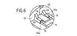
図5に明瞭に示されているように、各部品24(26)は、横梁型伸張部50をその前面26b(24b)上に前面から突き出した状態で具備している。伸張部50は、プラグ12の本体14がアダプター22の凹所46に挿入されるとき、並びに掛け金16が非作動状態にあるときに、伸張部50の端部50aが掛け金16と隣接するように配置されている。これは図6に明瞭に示されている。
【0027】
ここで図2、7、8A、及び8Bを参照して、プラグ装置がコード10のプラグ12に搭載される方法の説明が以下に続く。
【0028】
連接部品28、パッキング32、及びパッキング本体30は、全て図2に示すようにコード10上でプラグ12を越えて噛み合っている。次に、掛け金16のレバー18をプラグ12上に押し下げるとアダプター22の部品26がぴったり嵌められる。その後に、アダプターの第二の部品24がプラグの本体14上に搭載され、部品24及び26は同時に一緒に止め金で留められる。アダプター22は、次いで図7に示すようにプラグ12の本体14に固定される。
【0029】
プラグ12とアダプター22は次いでプラグ本体20に挿入される。アダプターの外壁24c、26cは、突起部を有するのが好ましく、プラグ本体20の内壁20bは90°づつ、ずらした四つの切り欠きを具備している。アダプター22は、従ってプラグ本体20の中で回転するのを妨げられ、四つの間接的に表現された位置の中の一つを占めることが出来る。
【0030】
最後に、図8A及び8Bに示すように、連接部品28はプラグ本体20に螺子締めされ、アダプター22がプラグ本体に対して相対的に並進運動するのを妨げる。パッキング本体30は次いで連接部品の螺子36に螺子締めされ、それによりパッキング32を圧縮しそれをコード10の上に留める。
【0031】
アダプター22の延伸部50の端部50aが非動作位置において掛け金16に隣接するので、プラグ12は、アダプター22に対して相対的に並進運動するのを妨げられるという事実は、強調されねば成らない。掛け金16は規格化された寸法のものである。発明のプラグ装置は、それ故、プラグが規格に従っている掛け金を有する全てのコードと共に使用することが出来る。
【0032】
連接部品28は、前記パッキング本体に嵌合するのに適したOリングを、その第二端部に備えていることが好ましい。ここで図9及び10を参照して、特に光コードに適合されたプラグ装置の実施態様を説明する。
【0033】
図9は、光コードを伴った光向けプラグ装置の、色々な構成要素の分解斜視図である。
【0034】
光コード60は、コード・プラグの本体62に搭載された端部を有し、それはフェルール65によって其処に固定されている。コード・プラグの本体外面は、以下に更に詳しく説明してある機械的掛け金64を具備している。
【0035】
プラグ装置そのものは、先ず、補完的光接続構成要素と共にそれを固定するためのナット68でその外面に取り付けられた、プラグ本体66から構成される。プラグ装置は、同じく、プラグ本体66の中に搭載するためのプラグ・アダプター70から成る。プラグ装置は、同じく、プラグ本体66に固定するための第一端部を有し、且つパッキング(図示されていない)内に固定するための反対側の端部72bを有する管状接続部品72を備えている。
【0036】
ここで図10Aを参照して、発明のプラグ装置を更に詳細に説明する。プラグ本体66は、その前方への並進運動を妨げるように、アダプター70の外面に形成された相補的肩部76と嵌合するのに適した肩部74をその内面66aに備えている。アダプター70は、並進するのを止めるための機械的装置78を取り付けることにより、プラグ本体66中に静止状態で保持できる。
【0037】
図に見られるように、アダプター70は、コード・プラグの本体の端部62aをその中に挿入できるような輪郭の軸方向開口80を有する。この断面は、光コードプラグの本体の機械的掛け金64を通すための先端の溝80を形作っている。より正確には、図10Aに見られるように、掛け金64の端部は、アダプターの軸方向通路80内に形成された肩部82と嵌合するのに適した突出部64aを具備している。突出部64aと肩82との嵌め合いはコードのプラグの本体62をアダプターに固定させることを可能にする。肩82は掛け金64がその非動作位置に保持されるような断面を形作っているということは、付け加えなければ成らない。
【0038】
接続部品72の第一端部72aは、プラグ本体66の後端に形成された螺子86と嵌合するのに適した螺子孔を有している。接続部品72の第二端部72bは、径の大きなハウジング88、及びパッキング92を収納するための肩部90を形作っている。未使用状態では、図10Aに見られるように、このパッキング92は、光芯線のプラグの本体62が自由に通れるような軸方向通路94を呈する。最後に、プラグ装置は、接続部品72の端部72bに設けられた外面螺子100と嵌合するのに適した螺子98を有する締付けナット96を備えている。このナット96は、光コードのプラグの本体62が自由に通るのに十分な直径(又はより一般的に寸法)の軸方向の開口102を有する。
【0039】
光コード60のプラグ62上に搭載するためのプラグ装置は、以下のように使用される。最初に、接続部品72、パッキング92、及び締付けナット96が光コード66の周りに噛み合わされる。次に、プラグの本体62の前部62aがアダプター70の軸方向通路80内で停止位置まで下げられた機械的掛け金64と噛み合わされる。コードのプラグ本体がアダプター70中に挿入した後で、掛け金64はコード・プラグの本体を肩部62と嵌合する突出部64aによりアダプターに固定する。この組立物はプラグ本体70にぴったり嵌められ、固定する装置78を挿入することによって並進運動が妨げられる。引き続いて、接続部品72がプラグ本体66の後部上に螺子締めされる。最後に、ナット96が接続部品72の後端部72b上にパッキング92を変形させるように螺子締めされ、光コード60の外面60aにパッキングを締付ける。これは、接続部品72とプラグ本体66で形作られる内容積を封止するのみでなく、上述の締付けによって光コード60を力学的にプラグ装置に固定するのにも役立つ。図10Bは、光コード60のプラグ62に搭載されたプラグ装置を示す。
【図面の簡単な説明】
【図1】 プラグの付いた標準電気コードを示す斜視図である。
【図2】 電気−向けプラグ装置の種々の構成要素を示す斜視図である。
【図3】 絶縁プラグ・アダプターを形成する二つの部品の詳細図である。
【図4】 絶縁プラグ・アダプターを形成する二つの部品の詳細図である。
【図5】 プラグ・アダプター部品の一つの側面図である。
【図6】 如何にしてコード・プラグがプラグ・アダプターに掛け金で留められるかを示す前の図の詳細図である。
【図7】 コード・プラグに搭載されたプラグ・アダプターを示す図である。
【図8】 プラグ装置を組み立てる際の、最後の二工程を示す図である。
【図9】 光向けプラグ装置の種々の構成要素を示す分解斜視図である。
【図10】 光コードに搭載されたプラグ装置を貫通する垂直断面図である。[0001]
BACKGROUND OF THE INVENTION
The present invention relates to a plug device for a standard electrical or optical connection cord having a plug having a body with a mechanical latch on the outer surface at least at one end thereof.
[0002]
[Prior art]
Currently, in the field of electrical erection, troublesome industrial networks are created by suppliers such as controllers: PROFIBUS from Siemens, FIP from Telemechanics.
[0003]
The current trend is that such a control device is used with a data transmission network that is open to each user, i.e. does not depend on the specific supplier of the control device, and builds a true world standard. It is to move away from the constraints associated with the supplier.
[0004]
Ethernet® , a network already used to interconnect computers and peripherals in the office, satisfies these requirements. The connector used is known as the “RJ45” type. The connection consists of a standard cord that is equally fitted at both ends and is sometimes shielded, and each plug has a mechanical latch on the outer surface that can be retracted by pushing one end. Presents the main body. As expected, the latch is used to secure mechanically when connecting to the jack.
[0005]
The attached FIG. 1 shows the end of a standard cord to which a standard type plug is attached in the RJ45 or RJ11 series. Shown is a
[0006]
This type of connector is well suited to the conditions that apply to the Ethernet standard, but it encounters industry that encounters liquid splashes, shocks, unexpected cord pulls, vibrations, electromagnetic interference, etc. It is never suitable for a dynamic environment. RJ45 or RJ11 type connection cords have the additional advantage of being current standard cords that are calibrated and available with two coated RJ45 or RJ11 plugs at each end.
[0007]
One solution to adapt the RJ45 electrical connector to the constraints of the industrial environment would be to disconnect the standard cords from the plugs and replace these plugs with conventional plugs used in the industrial environment. However, it will be understood that it presents two drawbacks:
First, because of the cover molding, additional costs are required to remove the original plug and then wire the new plug to the cord; and, second, two calibrated cover moldings The advantage of the cord being plugged is lost, which risks reducing the overall performance.
[0008]
Therefore, the real need to convert a standard electrical cord with an RJ45 plug or the like attached to a standard cord with a plug compatible with the industrial environment while avoiding the disadvantages of the solution outlined above. Sex exists.
[0009]
Similar or identical problems exist in the field where information is transmitted using optical signals. Standard fiber optic cords are available that have at least one plug body on at least one end, the body having a mechanical latch. Like electrical cords, this type of optical cord is not adapted for use in an industrial manufacturing environment.
[0010]
[Problems to be solved by the invention]
Therefore, there is the same need to convert standard optical connection cords into cords with plugs that are compatible with the industrial environment.
[0011]
[Means for Solving the Problems]
To achieve this object, the present invention provides a cord plug at the end having a body secured to the cord and having a mechanical latch on the outer surface to which is attached a control lever having an operating position and a stopping position. A plug device for a standard electrical or optical connecting cord is provided, the plug device having the following configuration:
・ Plug body;
A plug adapter that is separate from the plug body and has outer surface fixing means for meshing with the plug body;
A packing body including a cylindrical packing and a thread; and a second end having a first end for connection with the plug body and a thread for fitting into the thread of the packing body. Connecting parts having parts;
The plug adapter has an internal cross section suitable for housing the cord plug body, and further engages with the cord plug body and holds the latch of the cord plug body in the stop position. Having fixing means,
The packing body, the unused packing, and the connecting part each form an internal passage of sufficient dimensions to pass through the body of the cord plug; and when the packing body is screwed to the connecting part, The packing is compressed and clamped to a standard cord.
[0012]
It will be appreciated that the present invention allows the cord plug to be inserted into the components that make up the plug device such that the body of the plug is housed within the protective plug adapter. Furthermore, the plug adapter is shaped in such a way as to hold the mechanical latch of the cord plug in the stop position. In this way, the connection between the plug and the corresponding jack is made in a conventional manner only by the plug body.
[0013]
By compressing the packing, not only the plug device assembly is sealed, but the standard cord is also mechanically connected to the plug device in addition to the main locking action resulting from the mating of the plug adapter and cord plug It should be emphasized that it is fixed.
[0014]
Finally, above all, the present invention allows the cord to be adapted to an industrial environment without having to separate the plug from the cord. These advantages apply equally well to optical cords and electrical cords.
[0015]
In a preferred embodiment, the plug adapter consists of two different parts, each forming part of an internal cross section suitable for housing the body of the cord plug, whereby the two of the adapters. Two different parts can be fitted in a series of movements onto the body of the cord plug.
[0016]
In this preferred embodiment, the parts can be fitted in a series of movements in the lateral direction relative to the body of the cord plug so that it is easy to mount the cord plug in an insulated adapter. It will be understood that there is.
[0017]
In addition, when the latch is in its parked position, each part of the plug adapter includes a portion that supplementarily forms an adjoining object suitable for fitting a portion of the cord plug latch. . In this way, this property is particularly beneficial because the axial fixation between the cord plug and the plug adapter is obtained by a part of the plug having standardized dimensions. Plug adapters can therefore be used regardless of the type of cord or its manufacturer.
[0018]
Other features and advantages of the invention will become better apparent upon reading the following description of various embodiments of the invention given as non-limiting examples. The description refers to the accompanying drawings.
[0019]
DETAILED DESCRIPTION OF THE INVENTION
2 to 8 show a plug device provided in a preferred form for an electrical cord. First, with reference to FIG. 2, the description of the plug device assembly of the present invention follows.
[0020]
It is preferably composed of a
[0021]
The
[0022]
The connecting
[0023]
The packing
[0024]
With reference now to FIGS. 3-6, a description of a preferred embodiment of the
[0025]
The
[0026]
As clearly shown in FIG. 5, each component 24 (26) includes a cross
[0027]
With reference now to FIGS. 2, 7, 8A and 8B, a description of the manner in which the plug device is mounted on the
[0028]
The connecting
[0029]
The
[0030]
Finally, as shown in FIGS. 8A and 8B, the connecting
[0031]
It must be emphasized that the
[0032]
The connecting
[0033]
FIG. 9 is an exploded perspective view of various components of the optical plug device with an optical cord.
[0034]
The
[0035]
The plug device itself is first composed of a
[0036]
Referring now to FIG. 10A, the inventive plug device will be described in more detail. The
[0037]
As can be seen, the
[0038]
The
[0039]
The plug device for mounting on the
[Brief description of the drawings]
FIG. 1 is a perspective view showing a standard electric cord with a plug.
FIG. 2 is a perspective view showing various components of an electrical-oriented plug device.
FIG. 3 is a detailed view of two parts forming an insulating plug adapter.
FIG. 4 is a detailed view of two parts forming an insulating plug adapter.
FIG. 5 is a side view of one of the plug adapter parts.
FIG. 6 is a detail view of the previous figure showing how the cord plug is latched to the plug adapter.
FIG. 7 is a diagram showing a plug adapter mounted on a cord plug.
FIG. 8 is a diagram showing the last two steps when assembling the plug device.
FIG. 9 is an exploded perspective view showing various components of the optical plug device.
FIG. 10 is a vertical sectional view through a plug device mounted on an optical cord.
Claims (9)
・プラグ本体;
・プラグ本体とは別個のもので且つ前記プラグ本体と噛み合わせるための外面固定手段を有するプラグ・アダプター;
・円筒形のパッキングを含むパッキング本体;及び
・前記プラグ本体と接続するための第一端部、及び前記パッキング本体の螺子山に嵌合するための螺子山を備えた第二端部を有する連接部品;
前記プラグ・アダプターは、前記コード・プラグの本体を収納するために適した内部断面を有し、更にコード・プラグの本体と噛み合い且つコード・プラグの本体の前記掛け金を停止位置に保持するための固定手段を有し、
前記パッキング本体、未使用状態のパッキング、及び前記連接部品は、それぞれ全てコード・プラグの本体を通すのに十分な寸法の内部通路を形作っており;及び
パッキング本体を前記連接部品に螺子締めすると、前記パッキングは圧縮されて標準コードへ前記パッキングを締め付けることを特徴とする。A plug device for a standard electrical or optical connection cord with a cord plug at the end, having a body fixed to the cord and provided with a mechanical latch on the outer surface, the plug device comprising the following configuration It is characterized by:
・ Plug body;
A plug adapter that is separate from the plug body and has outer surface fixing means for meshing with the plug body;
A packing body including a cylindrical packing; and a connection having a first end for connection with the plug body and a second end with a thread for mating with a thread of the packing body. parts;
The plug adapter has an internal cross section suitable for housing the cord plug body, and further engages with the cord plug body and holds the latch of the cord plug body in the stop position. Having fixing means,
The packing body, the unused packing, and the connecting part each form an internal passage that is sufficiently sized to pass the body of the cord plug; and when the packing body is screwed to the connecting part, The packing is compressed and clamped to a standard cord.
Applications Claiming Priority (4)
| Application Number | Priority Date | Filing Date | Title |
|---|---|---|---|
| FR0201321A FR2835658B1 (en) | 2002-02-05 | 2002-02-05 | PLUG DEVICE FOR STANDARD ELECTRICAL CONNECTION CORD |
| FR0201321 | 2002-02-05 | ||
| FR0215512A FR2835657B1 (en) | 2002-02-05 | 2002-12-09 | PLUG DEVICE FOR A STANDARD CORD OF ELECTRIC OR OPTICAL LINK |
| FR0215512 | 2002-12-09 |
Publications (2)
| Publication Number | Publication Date |
|---|---|
| JP2003243108A JP2003243108A (en) | 2003-08-29 |
| JP4267932B2 true JP4267932B2 (en) | 2009-05-27 |
Family
ID=26213332
Family Applications (1)
| Application Number | Title | Priority Date | Filing Date |
|---|---|---|---|
| JP2003026654A Expired - Lifetime JP4267932B2 (en) | 2002-02-05 | 2003-02-04 | Plug device for standard electrical or optical connection cord |
Country Status (7)
| Country | Link |
|---|---|
| EP (1) | EP1333537B1 (en) |
| JP (1) | JP4267932B2 (en) |
| AT (1) | ATE293298T1 (en) |
| CA (1) | CA2418376C (en) |
| DE (1) | DE60300484T2 (en) |
| ES (1) | ES2242146T3 (en) |
| FR (1) | FR2835657B1 (en) |
Families Citing this family (22)
| Publication number | Priority date | Publication date | Assignee | Title |
|---|---|---|---|---|
| US6962445B2 (en) | 2003-09-08 | 2005-11-08 | Adc Telecommunications, Inc. | Ruggedized fiber optic connection |
| ATE430948T1 (en) * | 2004-02-19 | 2009-05-15 | Reichle & De Massari Fa | CONNECTOR HOUSING OF AN OPTICAL CONNECTOR FOR THE INDUSTRIAL ENVIRONMENT |
| CN100364182C (en) * | 2005-04-12 | 2008-01-23 | 中航光电科技股份有限公司 | Small volume fast separating RJ 45 electric connector |
| JP4771523B2 (en) * | 2005-08-18 | 2011-09-14 | 株式会社三桂製作所 | hood |
| DE202006011910U1 (en) * | 2005-11-09 | 2007-03-22 | Weidmüller Interface GmbH & Co. KG | Adapter for receiving a plug part |
| FR2906089B1 (en) * | 2006-09-18 | 2008-12-05 | Legrand France | HOOD FOR PREDETERMINED INFORMATION NETWORK SHEET, ASSEMBLY AND SYSTEM COMPRISING SAME |
| US7572065B2 (en) | 2007-01-24 | 2009-08-11 | Adc Telecommunications, Inc. | Hardened fiber optic connector |
| DE102007018389B4 (en) * | 2007-04-17 | 2012-01-12 | Mc Technology Gmbh | Connectors |
| US7677814B2 (en) | 2007-05-06 | 2010-03-16 | Adc Telecommunications, Inc. | Mechanical interface converter for making non-ruggedized fiber optic connectors compatible with a ruggedized fiber optic adapter |
| WO2008137893A1 (en) | 2007-05-06 | 2008-11-13 | Adc Telecommunications, Inc. | Interface converter for sc fiber optic connectors |
| US7686519B2 (en) | 2007-06-18 | 2010-03-30 | Adc Telecommunications, Inc. | Hardened fiber optic housing and cable assembly |
| US7942590B2 (en) | 2007-12-11 | 2011-05-17 | Adc Telecommunications, Inc. | Hardened fiber optic connector and cable assembly with multiple configurations |
| JP5892600B2 (en) * | 2012-05-22 | 2016-03-23 | 日本航空電子工業株式会社 | Connector device |
| JP5866734B2 (en) | 2012-12-27 | 2016-02-17 | ヒロセ電機株式会社 | Connector, connector device using the connector, and connector member used for the connector |
| EP3014322B1 (en) | 2013-06-27 | 2018-09-19 | CommScope Connectivity Belgium BVBA | Fiber optic cable anchoring device for use with fiber optic connectors and methods of using the same |
| CN103594862A (en) * | 2013-11-25 | 2014-02-19 | 济南中维世纪科技有限公司 | Video camera tail circuit connector |
| EP2960695B1 (en) * | 2014-06-24 | 2020-08-12 | TE Connectivity Nederland B.V. | Connector for a cable and connector assembly |
| US9450338B2 (en) * | 2014-08-06 | 2016-09-20 | Molex, Llc | High speed connector with ruggedized exterior structure and shielding |
| FR3037666A1 (en) * | 2015-06-16 | 2016-12-23 | Nexans | FIBER OPTIC CONNECTOR DEVICE |
| JP6805408B2 (en) * | 2015-10-30 | 2020-12-23 | 群馬県 | Power generation equipment and power generation method using fuel cells |
| CN105870698A (en) * | 2016-05-16 | 2016-08-17 | 苏州博豪精密机械有限公司 | Disc shell for plug |
| KR102395601B1 (en) * | 2021-09-13 | 2022-05-10 | 주식회사유비씨에스 | Waterproof assembly for electric cable |
Family Cites Families (3)
| Publication number | Priority date | Publication date | Assignee | Title |
|---|---|---|---|---|
| FR1409281A (en) * | 1964-05-06 | 1965-08-27 | Connector for coaxial cables and shielded cables with one or more conductors | |
| JP3604314B2 (en) * | 2000-02-03 | 2004-12-22 | 松下電器産業株式会社 | XSR cable connector |
| US6257923B1 (en) * | 2000-02-03 | 2001-07-10 | Phillips & Temro Industries Inc. | Dual media connector for a vehicle |
-
2002
- 2002-12-09 FR FR0215512A patent/FR2835657B1/en not_active Expired - Lifetime
-
2003
- 2003-01-23 AT AT03290164T patent/ATE293298T1/en active
- 2003-01-23 DE DE60300484T patent/DE60300484T2/en not_active Expired - Lifetime
- 2003-01-23 ES ES03290164T patent/ES2242146T3/en not_active Expired - Lifetime
- 2003-01-23 EP EP03290164A patent/EP1333537B1/en not_active Expired - Lifetime
- 2003-02-04 JP JP2003026654A patent/JP4267932B2/en not_active Expired - Lifetime
- 2003-02-04 CA CA2418376A patent/CA2418376C/en not_active Expired - Lifetime
Also Published As
| Publication number | Publication date |
|---|---|
| FR2835657B1 (en) | 2004-08-06 |
| EP1333537B1 (en) | 2005-04-13 |
| DE60300484T2 (en) | 2006-02-23 |
| DE60300484D1 (en) | 2005-05-19 |
| CA2418376C (en) | 2010-10-26 |
| FR2835657A1 (en) | 2003-08-08 |
| ES2242146T3 (en) | 2005-11-01 |
| EP1333537A1 (en) | 2003-08-06 |
| JP2003243108A (en) | 2003-08-29 |
| ATE293298T1 (en) | 2005-04-15 |
| CA2418376A1 (en) | 2003-08-05 |
Similar Documents
| Publication | Publication Date | Title |
|---|---|---|
| JP4267932B2 (en) | Plug device for standard electrical or optical connection cord | |
| US6817902B2 (en) | Plug device for a standard electrical or optical connection cord | |
| US7641396B2 (en) | Connection device with a cable gland having housing parts enabling relative movement therebetween | |
| EP2579396B1 (en) | Shielded enclosure assembly for at least one in particular standardized connector on a cable | |
| US8764485B2 (en) | Electrical plug connector | |
| US20110201228A1 (en) | Plug connector with adapter | |
| CA2500767A1 (en) | Electrical plug-in connector | |
| TW201104983A (en) | An interconnection system | |
| KR20090085652A (en) | Miniature circular connector system | |
| US20030148652A1 (en) | Plug device for a standard electrical connection cord | |
| CN201708366U (en) | Connector component | |
| JP5892600B2 (en) | Connector device | |
| CN117254292A (en) | Multi-signal transmission connector for wire harness wiring and plug and socket connector | |
| CN102214872B (en) | Connector component | |
| US12021327B2 (en) | Signal outlet assembly with shielding wire grounded to sidewall of the housing | |
| CN210156638U (en) | Pluggable wiring plug structure | |
| CN209993793U (en) | Multifunctional composite connector | |
| CN110380276B (en) | Multifunctional composite connector | |
| JP2009086562A (en) | Connector with built-in photoelectric conversion circuit | |
| CN217405827U (en) | Communication connecting device and communication connecting wire | |
| JPH05226027A (en) | Optical-electric composite connector | |
| CN209045893U (en) | A kind of plug-assembly and connection equipment with waterproofness | |
| CN217720175U (en) | Split type socket of connector | |
| CN112038827B (en) | Argon atmosphere hot chamber is with sealed electric connection device of remote plug operation | |
| CN219393769U (en) | Connector |
Legal Events
| Date | Code | Title | Description |
|---|---|---|---|
| A621 | Written request for application examination |
Free format text: JAPANESE INTERMEDIATE CODE: A621 Effective date: 20060112 |
|
| A131 | Notification of reasons for refusal |
Free format text: JAPANESE INTERMEDIATE CODE: A131 Effective date: 20080318 |
|
| A601 | Written request for extension of time |
Free format text: JAPANESE INTERMEDIATE CODE: A601 Effective date: 20080617 |
|
| A602 | Written permission of extension of time |
Free format text: JAPANESE INTERMEDIATE CODE: A602 Effective date: 20080620 |
|
| A521 | Request for written amendment filed |
Free format text: JAPANESE INTERMEDIATE CODE: A523 Effective date: 20080912 |
|
| TRDD | Decision of grant or rejection written | ||
| A01 | Written decision to grant a patent or to grant a registration (utility model) |
Free format text: JAPANESE INTERMEDIATE CODE: A01 Effective date: 20090127 |
|
| A01 | Written decision to grant a patent or to grant a registration (utility model) |
Free format text: JAPANESE INTERMEDIATE CODE: A01 |
|
| A61 | First payment of annual fees (during grant procedure) |
Free format text: JAPANESE INTERMEDIATE CODE: A61 Effective date: 20090219 |
|
| R150 | Certificate of patent or registration of utility model |
Ref document number: 4267932 Country of ref document: JP Free format text: JAPANESE INTERMEDIATE CODE: R150 Free format text: JAPANESE INTERMEDIATE CODE: R150 |
|
| FPAY | Renewal fee payment (event date is renewal date of database) |
Free format text: PAYMENT UNTIL: 20120227 Year of fee payment: 3 |
|
| FPAY | Renewal fee payment (event date is renewal date of database) |
Free format text: PAYMENT UNTIL: 20120227 Year of fee payment: 3 |
|
| FPAY | Renewal fee payment (event date is renewal date of database) |
Free format text: PAYMENT UNTIL: 20130227 Year of fee payment: 4 |
|
| R250 | Receipt of annual fees |
Free format text: JAPANESE INTERMEDIATE CODE: R250 |
|
| FPAY | Renewal fee payment (event date is renewal date of database) |
Free format text: PAYMENT UNTIL: 20130227 Year of fee payment: 4 |
|
| FPAY | Renewal fee payment (event date is renewal date of database) |
Free format text: PAYMENT UNTIL: 20140227 Year of fee payment: 5 |
|
| R250 | Receipt of annual fees |
Free format text: JAPANESE INTERMEDIATE CODE: R250 |
|
| R250 | Receipt of annual fees |
Free format text: JAPANESE INTERMEDIATE CODE: R250 |
|
| R250 | Receipt of annual fees |
Free format text: JAPANESE INTERMEDIATE CODE: R250 |
|
| R250 | Receipt of annual fees |
Free format text: JAPANESE INTERMEDIATE CODE: R250 |
|
| R250 | Receipt of annual fees |
Free format text: JAPANESE INTERMEDIATE CODE: R250 |
|
| R250 | Receipt of annual fees |
Free format text: JAPANESE INTERMEDIATE CODE: R250 |
|
| R250 | Receipt of annual fees |
Free format text: JAPANESE INTERMEDIATE CODE: R250 |
|
| R250 | Receipt of annual fees |
Free format text: JAPANESE INTERMEDIATE CODE: R250 |
|
| R250 | Receipt of annual fees |
Free format text: JAPANESE INTERMEDIATE CODE: R250 |
|
| R250 | Receipt of annual fees |
Free format text: JAPANESE INTERMEDIATE CODE: R250 |
|
| EXPY | Cancellation because of completion of term |