JP4265794B2 - Drainage device for intelligent flush toilet - Google Patents
Drainage device for intelligent flush toilet Download PDFInfo
- Publication number
- JP4265794B2 JP4265794B2 JP2004533829A JP2004533829A JP4265794B2 JP 4265794 B2 JP4265794 B2 JP 4265794B2 JP 2004533829 A JP2004533829 A JP 2004533829A JP 2004533829 A JP2004533829 A JP 2004533829A JP 4265794 B2 JP4265794 B2 JP 4265794B2
- Authority
- JP
- Japan
- Prior art keywords
- bubbles
- toilet
- bubble generator
- user
- control signal
- Prior art date
- Legal status (The legal status is an assumption and is not a legal conclusion. Google has not performed a legal analysis and makes no representation as to the accuracy of the status listed.)
- Expired - Fee Related
Links
Images
Classifications
-
- E—FIXED CONSTRUCTIONS
- E03—WATER SUPPLY; SEWERAGE
- E03D—WATER-CLOSETS OR URINALS WITH FLUSHING DEVICES; FLUSHING VALVES THEREFOR
- E03D5/00—Special constructions of flushing devices, e.g. closed flushing system
- E03D5/10—Special constructions of flushing devices, e.g. closed flushing system operated electrically, e.g. by a photo-cell; also combined with devices for opening or closing shutters in the bowl outlet and/or with devices for raising/or lowering seat and cover and/or for swiveling the bowl
- E03D5/105—Special constructions of flushing devices, e.g. closed flushing system operated electrically, e.g. by a photo-cell; also combined with devices for opening or closing shutters in the bowl outlet and/or with devices for raising/or lowering seat and cover and/or for swiveling the bowl touchless, e.g. using sensors
Landscapes
- Engineering & Computer Science (AREA)
- Aviation & Aerospace Engineering (AREA)
- Health & Medical Sciences (AREA)
- Life Sciences & Earth Sciences (AREA)
- Hydrology & Water Resources (AREA)
- Public Health (AREA)
- Water Supply & Treatment (AREA)
- Sanitary Device For Flush Toilet (AREA)
Description
本発明は知能型水洗式便器の排水装置に係るものであって、さらに詳しくは、一般家庭や公共化粧室に設けられる洋便器の排水のために、センサーが人を感知し、その感知された時間に従って大小便を判断して浮力器に気泡を差等的に供給することにより、気泡の充填に従って上下運動をする浮力器によってサイホン蓋が開閉され排水機能を行なう知能型水洗式便器の排水装置に関するものである。 The present invention relates to a drainage device for an intelligent flush toilet. More specifically, the sensor senses a person for draining a western toilet provided in a general household or public restroom, and the sense is detected. Intelligent flush toilet drainage device that siphon lid is opened and closed by a buoyancy device that moves up and down according to the filling of bubbles by judging the size of urine according to time and supplying bubbles differentially. It is about.
一般的に、大小便兼用に使用される水洗式便器は、陶器からなった本体と、その後方に位置され汚物洗浄用水が貯蔵されるタンクとからなり、従来の便器では便器内の汚物を排出するために水槽には一定量の水が貯蔵され、それを流して処理する方式を用いる。 In general, a flush toilet used for both large and small stools consists of a main body made of earthenware and a tank that is located behind it and stores wastewater for washing waste. In conventional toilets, waste in the toilet is discharged. In order to do this, a certain amount of water is stored in the aquarium, and the system is used by flowing it.
最近では、上記水洗式便器を改良した便器が一般公共建物に導入されている。上記自動式便器は用便をしようとする人の有無を赤外線センサーで感知し、これを主コントロール部で処理して洋便器または小便器の排水バルブに連結されたソレノイドバルブを作動させて排水させる方法を用いている。 Recently, toilets improved from the flush toilets have been introduced into general public buildings. The above-mentioned automatic toilet uses the infrared sensor to detect the presence or absence of the person who is going to use the stool, treats it with the main control unit, and activates the solenoid valve connected to the drainage valve of the urinal or urinal to drain the water. The method is used.
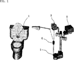
さらに他の方法としては、図1に示したように、利用者の有無を便器蓋に設けられた赤外線センサー部1で感知してこれを主コントロール部2で処理し、前記処理されたデータに応じてモーター3にてチェ-ン調節装置4によってチェ-ンに連結されたサイホンの蓋部5を上下運動で開閉することにより、水槽の水が流されて用便の処理が行なわれるようにする方法を用いている
上記ソレノイドバルブを使用する従来技術の水洗式便器は、給水パイプに高い圧力を必要としていた。一般公共建物に設けられる場合には、高い圧力で消費電力が少ないパイロット方式のソレノイドバルブを利用して、従来技術の水洗式便器の具現が可能であった。しかしながら、水槽に水を満たしてから用便の処理をする一般家庭の便器では、十分なパイプ内圧力が保障されないので上記ソレノイドバルブの具現は難しいとの問題点がある。
As another method, as shown in FIG. 1, the presence or absence of a user is detected by an
また別途に、一般家庭においては家庭用便器に適応させて開発された最大直径1インチの低水圧で、流体量が少なくても作動することができる直動式ソレノイドバルブの導入が進んでいる。しかしながら上記タイプのソレノイドバルブには排水時間が長いことと、低水圧と低流体量で作動するために便器内の汚物が完全に排水されないという欠点がある。 Separately, in general households, the introduction of a direct acting solenoid valve that can be operated even with a small amount of fluid with a low water pressure of 1 inch maximum diameter, which was developed to be adapted to a domestic toilet. However, the solenoid valve of the above type has a disadvantage that the drainage time is long and the waste in the toilet is not completely drained because it operates at a low water pressure and a low fluid amount.
さらに、上記モーターを使用する従来技術の水洗式便器はその作動環境が多湿であるため耐久性に問題があり、多数筋のチェーンが使用されるため正常動作が不確実な問題点がある。 Further, the flush toilet of the prior art using the motor has a problem in durability because its operating environment is humid, and there is a problem that normal operation is uncertain because a multi-strand chain is used.
本発明は上記のような問題点を解決するために提案されたものであって、その目的は、センサーにより使用者を感知すると制御部の制御信号によって気泡が浮力器に供給され、その浮力によって浮力器が上昇してタンクに盛れた水の排水口を塞いでいるサイホンの蓋を開閉することにより洋便器の排水機能が自動的に行なわれるようにする知能型便器排水装置を提供することである。 The present invention has been proposed in order to solve the above-described problems. The object of the present invention is to supply bubbles to a buoyancy device according to a control signal from a control unit when a user is detected by a sensor. By providing an intelligent toilet drainage device that automatically performs the drainage function of the Western toilet by opening and closing the lid of the siphon that blocks the drainage port of the water built up in the tank when the buoyancy device rises is there.
さらに、センサーが便器使用者の使用時間を感知しそれを制御部で定められた時間に従って大小便を判断し、水槽の水を差等的に放出させることにより、水の節約が可能になるようにする知能型水洗式便器排水装置を提供することである。 In addition, the sensor senses the usage time of the toilet user, judges the size of the urine according to the time set by the control unit, and discharges the water in the aquarium differentially so that water can be saved. It is to provide an intelligent flush toilet drain device.
上記の目的を達成するための本発明による知能型水洗式便器の排水装置は、便器の外部に設置され便器利用者の有無を感知するセンサー部;上記センサー部で便器利用者が感知されれば、その感知継続時間を所定基準時間と比較して所定時間以上である場合、大便に判断し、用便制御信号を送信する制御部;上記制御部の用便制御信号に従って、気泡を発生させる気泡発生器;上記気泡発生器と接続され気泡の供給と排出を制御するソレノイドバルブ;上記気泡発生器から気泡の供給を受けて気泡の充填有無に従って、上下運動を行う浮力器;および上記浮力器の上下運動に従って開閉され水槽の水を排水させるサイホン蓋を含むことを特徴とする。 In order to achieve the above object, the drainage device of the intelligent flush toilet according to the present invention includes a sensor unit installed outside the toilet to sense the presence or absence of a toilet user; if the toilet user is detected by the sensor unit , A control unit that determines the stool and transmits a stool control signal when the perceived duration is greater than or equal to a predetermined time compared to a predetermined reference time; a bubble that generates bubbles according to the stool control signal of the control unit; A solenoid valve connected to the bubble generator to control supply and discharge of bubbles; a buoyancy device that receives supply of bubbles from the bubble generator and moves up and down according to whether the bubbles are filled; and It includes a siphon lid that is opened and closed according to vertical movement and drains water from the aquarium.
好ましくは、上記用便制御信号は大便制御信号と小便制御信号とに区分され、大小便制御信号に従って差等的に気泡を発生させ、上記サイホン蓋の行程を制限するように水槽の内部に付着されるリミットブラケットをさらに含むことを特徴とする。 Preferably, the stool control signal is divided into a stool control signal and a urine control signal, and bubbles are generated in a differential manner according to the stool control signal and adhered to the inside of the water tank so as to limit the stroke of the siphon lid. And a limit bracket to be included.
さらに好ましくは、上記制御部は使用者がメロデイーボタンを押すとスピカ-を通じて所定時間メロデイーが発生するようにするメロデイーチップ;およびセンサー部で感知された使用者の便器利用時間が30分を越えるとこれを指定された電話に自動ダイアリングするようにするホームセキユリテイーに連結させる緊急信号作動装置をさらに含むことを特徴とする。 More preferably, the control unit is configured to generate a melody for a predetermined time through a speaker when the user presses the melody button; and when the user's toilet usage time detected by the sensor unit exceeds 30 minutes. It further includes an emergency signal actuating device that is connected to a home security that allows automatic dialing to a designated telephone.
さらに好ましくは、上記ソレノイドバルブはT型コネクターを通じて平行に移動可能なチューブに連結されており、更に柔軟な素材のチューブにより浮力器とも連結されている。浮力器に気泡が提供されるとき、ソレノイドバルブの排気口は常に閉じられており、浮力器から気泡が排出されるときにのみソレノイドバルブの排気口は開かれる。 More preferably, the solenoid valve is connected to a tube movable in parallel through a T-shaped connector, and is also connected to a buoyancy device by a tube made of a flexible material. When bubbles are provided to the buoyancy device, the exhaust port of the solenoid valve is always closed, and only when the bubbles are discharged from the buoyancy device, the exhaust port of the solenoid valve is opened.
以下、図面を参照して本発明の好ましい実施例を詳しく説明する。 Hereinafter, preferred embodiments of the present invention will be described in detail with reference to the drawings.
以下において、本発明はセンサーが洋便器の利用者を感知してその経過時間に従って大小便を区分して、気泡発生器から気泡の供給を受けて上下運動を行う浮力器によってサイホンの蓋が開閉されることにより、自動的に排水機能を行なう知能型水洗式便器排水装置を好ましい実施例で説明するが、本発明の技術的思想はこれに制限されることなく、当業者によって修正され多様に実施され得るのは勿論である。 In the following, the present invention detects the user of a toilet bowl and classifies large and small urine according to the elapsed time, and the siphon lid is opened and closed by a buoyancy device that moves up and down with the supply of bubbles from the bubble generator. Thus, an intelligent flush toilet drainage device that automatically performs a drainage function will be described in a preferred embodiment. However, the technical idea of the present invention is not limited to this, and various modifications can be made by those skilled in the art. Of course, it can be implemented.
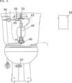
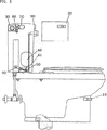
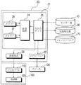
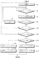
図2は本発明が適用された知能型水洗式便器の排水装置の正面を示す図面であり、図3は本発明が適用された知能型水洗式便器排水装置の側面を示す図面であり、図4は本発明が適用された知能型水洗式便器の排水装置の制御部のブロック図であり、図5は本発明が適用された知能型水洗式便器の排水装置の制御部の動作を示す流れ図である。 FIG. 2 is a front view of an intelligent flush toilet drainage apparatus to which the present invention is applied, and FIG. 3 is a side view of an intelligent flush toilet drainage apparatus to which the present invention is applied. 4 is a block diagram of the control unit of the drainage device of the intelligent flush toilet to which the present invention is applied, and FIG. 5 is a flowchart showing the operation of the control unit of the drainage device of the intelligent flush toilet to which the present invention is applied. It is.
本発明が適用された知能型水洗式便器の排水装置は便器利用者の有無を感知するセンサー部10、 上記センサー部10から感知された利用者の便器利用時間で大小便を判断して制御信号を送信する制御部20、上記制御部20の制御信号に従って、大小便に対して差等的に気泡を発生させる気泡発生器30、上記気泡発生器30から供給された気泡の充填有無に従って上下運動をする浮力器40、上記浮力器40の上下運動によって開閉され水を排水させるサイホン蓋50、上記浮力器40に充填された気泡を放出させるように誘導するソレノイドバルブ70から構成される。
The drainage device of an intelligent flush toilet to which the present invention is applied has a
図2ないし図3を参照して本発明の実施例に基づいた知能型水洗式便器排水装置に対してもう少し詳しく説明する。 An intelligent flush toilet drain device according to an embodiment of the present invention will be described in more detail with reference to FIGS.
上記センサー部10は水洗式洋便器の外部に設置されて便器を利用する人の有無を持続的に感知する。
The
この時、上記センサー部10は、赤外線を放出し感知された物体から赤外線が反射されることによりその物体を感知するようにするように便器の下側に設置される。センサーの感知範囲は座っている人は勿論、便器周囲に倒れている人も感知できるように上側を斜めに感知する方向に設ける事が好ましい。
At this time, the
センサー部10が感知した信号を制御部20に送信した後、次に大小便信号を送信するために、その利用時間の開始を始めるとともにあらかじめ制御部に設定された利用時間との比較も開始する。
After transmitting the signal sensed by the
図4に示されるように、マイクロプロセッサー21は制御部20は演算装置24、入出力ポート25、タイマー26、メモリ部27、複数のメロデイーを演奏することのできるメロデイーチップ22、緊急時に電話連絡が可能な緊急信号作動装置23を内蔵している。メロデイーチップ22とは便器利用者がボタンを押したとき、一定期間メロデイーが流れるようになっている。緊急信号作動装置23は非常事態連絡用電話に接続されており、センサーが利用者の緊急事態を感知したときには自動的に緊急連絡先に連絡するように設定されている。
As shown in FIG. 4, the
センサー10が便器利用者の存在を感知して、その信号を入出力ポート25に送信してからマイクロプロセッサー21は作動する。それから、タイマー26が大小便のいずれかであるという信号を送信するために、便器利用時間を測定する。この時、演算装置24は上記メモリ27に貯蔵される人体感知時間をそれぞれ「使用者安全時間」、「非使用時間」、「大小便境界時間」等に区分された所定時間と比較する。
The
演算装置24がタイマー26より実際の便器利用者の使用時間のデータを受信して、メモリー部27の設定時間との比較を元に用便を区別する。メモリ27は利用者の感知時間をそれぞれ「使用者安全時間」、「未使用時間」、「大小便境界時間」等、所定時間に区分して貯蔵している。
The
図5の流れ図を用いて本発明である知能型水洗式便器の排水装置の詳細について説明する。使用者が便器の使用開始を始めたときからセンサー部10が使用開始信号を制御部20へ送信する。その後、演算装置24が使用時間の測定を開始する。上記演算装置24による便器使用時の測定時間が「使用者安全時間」と設定されている30分を超えると、使用者に異常が生じたと判断して緊急信号作動装置23に緊急信号を送信して、ホームセキュリテイ-システム100を作動させる。
The details of the drainage device of the intelligent flush toilet according to the present invention will be described with reference to the flowchart of FIG. The
上記ホームセキュリテイ-システム100はテレホンモデム110と連結されており、救助隊や119番および親族と連絡を取る事が可能である。
The
また、使用者がトイレの個室に入っただけですぐに立ち去った場合や、使用する目的ではなく便器およびセンサーの前を横切るなどした場合にもセンサー10は継続して使用者の有無を感知するために赤外線を放出し続ける。またセンサー10が10秒間継続して便器の使用者を感知しない場合、上記演算装置24はリセット後、初期設定、「非使用時間」に戻る。
In addition, the
また、便器使用時間が10秒以上であり、120秒以下である場合、上記演算装置24が小便であると判断してその信号を送信する。センサー10が120秒以上の便器使用時間を感知した場合、上記演算装置24が大便であると判断してその信号を送信する。
When the toilet use time is 10 seconds or longer and 120 seconds or shorter, the
この時点では、以上提示した「使用者安全時間」、「非使用時間」、「大小便境界時間」に対して、それぞれ例を挙げて記述したが、これに限定されるものではない。
便器使用者が用便の音や単純に気分良く用を足したい時に、便器使用者は制御部20に設置されているメロデイーボタンを使用してもよい。それにより、メロデイーチップ22に登録されたメロデイーが一定の期間スピーカー130より出力され、用便を足しているときの音を覆う。
At this point, the above-described “user safety time”, “non-use time”, and “large and small stool boundary time” have been described with examples, but the present invention is not limited thereto.
When the toilet user wants to use the sound of the stool or simply feel good, the toilet user may use a melody button installed in the
以上で例示した制御部20にはマイクロプロセッサー21の制御を目的として設計された8ビット、80C31チップを利用する事が好ましい。前記気泡発生器30は前記制御部20の出力信号に応じて気泡を発生させるが、その信号内容に従ってそれぞれ異なる時間の間気泡をさせるよう。
It is preferable to use an 8-bit 80C31 chip designed for the control of the
例えば、気泡発生器30は小便の場合は8秒間作動し、大便である場合は12秒間作動させ気泡を発生させる。
For example, the
また気泡を発生するための気泡発生器作動時間は上記に限定されるものではない。 Further, the bubble generator operating time for generating bubbles is not limited to the above.
上記ソレノイドバルブ70はT型コネクター80でもって上記気泡発生器30と平行に接続され、更に柔軟な素材のチューブ42を通して浮力器40と接続されている。上記気泡発生器30から発生された気泡はT型コネクターを通って浮力器40へと運ばれる。気泡が浮力器40に供給されるまで、ソレノイドバルブ70の排気口は常に閉じられている(N.C.)。ソレノイドバルブ70は制御部20からの気泡を放出せよという信号を受信すると排気口が開放され、気泡が浮力器40へと放出される。
The
浮力器40の上部分は柔軟な素材のチューブ42に接続されており、浮力器40の底部分に入水および排水が可能な水孔41が形成されている。
An upper portion of the
通常、浮力器40はその中身を水で満たされ、沈むようになっている。そして気泡発生器30の気泡が供給された時、供給された気泡の圧力によって水孔41へ水が排水され、浮力器40は気泡で充填され該浮力によって上昇するようになる。
Normally, the
さらに、上記ソレノイドバルブ70の排気口が開放されると水孔41を通じて水が入水され、浮力器40が再び沈むようになる。
Further, when the exhaust port of the
一方、上記サイホン蓋50は上記浮力器40に連結され、制御信号に従って排水量を調節する。
Meanwhile, the siphon
さらに、上記サイホン蓋50は水槽内部に設置されたリミットブラケット60に連結されている。上記リミットブラケット60により所定角度でサイホン蓋50の開放を制限すると共に制御信号の内容により流水量を制御している。
Further, the siphon
また、サイホン蓋50は手動レバー90に連結されており、緊急事態において排水を手動で行うことも可能である。
Further, the siphon
上記のような構成による本発明による知能型水洗式便器排水装置の一実施例に対する動作を図4と図5とを参照して詳しく説明すれば次のとおりである。 The operation of the intelligent flush toilet drainage apparatus according to the present invention having the above-described configuration will be described in detail with reference to FIGS. 4 and 5. FIG.
第二段階の手順として、マイクロプロセッサー21の入出力ポート25とタイマー26を初期化する。第四段階の手順として、マイクロプロセッサー21はローレベル信号がポート1-7へと正常に送信できているか確認する。
As a procedure of the second stage, the input /
第六段階の手順としては、マイクロプロセッサー21のタイマー26がローレベル信号の継続して送信されている時間を感知する。感知された時間はリアルタイムで記録され、メモリ部27の所定時間と比較される。第八段階の手順として、該感知時間が30分以上継続すれば、マイクロプロセッサー21によって便器使用者が緊急状況に陥っていると判断される。第七段階の手順としてはテレホンモデム110と連結されているホームセキュリテイ-システム100が、緊急信号作動装置23を作動させ、救助隊や119番および親族へ緊急信号を送信する事が可能である。
In the sixth step, the
一方で、マイクロプロセッサー21の中のメモリ部27はハイレベル信号がセンサー部10に受信されるまでの実時間を記録しておく。
On the other hand, the
第十段階としては、マイクロプロセッサー21内に設置された演算装置24が上記ハイレベル信号を感知した後、第十二段階としてメモリ部27内の所定の設定時間と比較する。また、使用者がトイレの個室に入っただけですぐに立ち去った場合や、使用する目的ではなく便器およびセンサーの前を横切るなどした場合にもセンサー10は継続して使用者の有無を感知するために赤外線を放出し続ける。またセンサー10が10秒間継続して便器の使用者を感知しない場合、上記演算装置24はリセット後、初期設定、「非使用時間」に戻る。
In the tenth stage, after the
第十四段階としては、便器使用時間が10秒以上であり、120秒以下である場合、上記演算装置24が小便であると判断してその信号を送信する。センサー10が120秒以上の便器使用時間を感知した場合、上記演算装置24が大便であると判断してその信号を送信する。その後、気泡発生器30が気泡をポート1−0を通じて浮力器に供給する。
As the fourteenth stage, when the toilet use time is 10 seconds or longer and 120 seconds or shorter, the
第十五段階としては、気泡発生器30が、ポート1−0を通じてマイクロプロセッサー21より受信した大便信号に基づいて12秒間に渡り要求された気泡を生成する。第十六段階としてはポート1−1を通じてソレノイドバルブ70を10秒間作動させる。第十七段階として、気泡発生器30が、ポート1−0を通じてマイクロプロセッサー21より受信した小便信号に基づいて8秒間に渡り要求された気泡を生成する。第十八段階として、ポート1−1を通じてソレノイドバルブ70を10秒間作動させる。
As the fifteenth stage, the
上記ソレノイドバルブ70はT型コネクター80でもって上記気泡発生器30と平行に接続され、更に柔軟な素材の移動チューブ42を通して浮力器40と接続されている。上記気泡発生器30で上記浮力器40に気泡を供給する場合には、上記ソレノイドバルブ70が閉まることで、気泡が大気に漏出されないように作用し、気泡が供給されると、(N.C.)上記浮力器40が浮き始める。上記浮力器40から大気に気泡を放出させる時には上記ソレノイドバルブ70が開くことにより上記気泡発生器30と上記移動チューブ42の連結が遮断され、上記浮力器40内の気泡が上記移動チューブ42を通じて大気に放出される。
The
常に便器の水槽には一定量の推量が維持されている。浮力器40は柔軟な素材のチューブ42に接続されており、その底部分に入水および排水が可能な水孔41が形成されている。浮力器40はその中身を水で満たされ、気泡発生器30の気泡が供給された時、供給された気泡の圧力によって水孔41へ水が排水され、浮力器40は気泡で充填され該浮力によって沈む。
A constant amount of guessing is always maintained in the toilet bowl. The
制御信号に伴って排水量を調節するサイホン蓋50に浮力器40は連結されている。さらに、上記サイホン蓋50は水槽内部に設置されたリミットブラケット60に連結されている。上記リミットブラケット60により所定角度でサイホン蓋50の開放を制限すると共に制御信号の内容により流水量を制御している。
The
一方、排水量は浮力器を満たした空気量によって調節される。気泡発生器30が浮力器40に小便の場合は8秒間、大便の場合は12秒間気泡を供給する。
On the other hand, the amount of drainage is adjusted by the amount of air filling the buoyancy device. When the
マイクロプロセッサー21はソレノイドバルブ70を調節してポート1−1を通して大小便に関わらず、便器内の汚物を流す。この時点では浮力器内の空気はソレノイドバルブ70の排気口を通して放出されている。
この時、上記浮力器40には気泡が抜け出るのと同時に水孔41を通じて水が満たされるようになり、サイホン蓋50に掛かる水の圧力と少なくなった浮力との力の差異によってサイホン蓋50は閉じられるようになる。
At this time, the
以後、水槽には排水された一定水位が再度満ちるまで水が供給されるようになる。 Thereafter, water is supplied to the water tank until the drained water level is filled again.
以上検討したとおり、本発明が属する技術分野で通常の知識を有する者において本発明の技術的思想を外れない範囲内で種々な置換、変形および変更が可能であるので、前述の実施例および添付の図面に限定されるものではない。 As discussed above, various substitutions, modifications and changes can be made without departing from the technical idea of the present invention by those who have ordinary knowledge in the technical field to which the present invention belongs. It is not limited to the drawings.
以上検討したとおり、本発明によって知能型水洗式便器排水装置は外部に設置されたセンサー部が使用者を感知しこれに従って、気泡発生器の気泡が充填される浮力器の上下運動によって水槽の水が排水されることにより、便器の大小便の洗浄のための排水が自動的に行なわれる効果がある。 As described above, according to the present invention, the intelligent flush toilet drainage device detects the user by the sensor unit installed outside, and according to this, the buoyancy device filled with bubbles of the bubble generator moves the water in the aquarium. As a result, the drainage for washing the urinals of the toilet bowl is automatically performed.
さらに、センサー部が用便をしようとする使用者の便器利用時間を感知し、これを制御部が所定基準時間と比較して大小便を区別して、これに従って差等的に排水が行なわれることにより、大小便の区分なしに同一量で排水される既存の排水装置に比べて水を節約することができる効果がある。 Furthermore, the sensor unit senses the toilet use time of the user who wants to use the stool, the control unit compares this with a predetermined reference time, distinguishes large and small stools, and the drainage is performed according to this difference. Thus, there is an effect that water can be saved as compared with an existing drainage device that drains in the same amount without separating large and small stools.
さらに、センサー部が便器の下で感知機能を行い、これを受信した制御部が便器使用者の便器利用時間が度を過ぎて長い、使用者が便器の周囲に倒れているようであればこれを使用者の親姻戚らに自動ダイアリングするようになるホームセキュリテイ-システムを備えることにより、老弱者および肢体不自由者を対象にする化粧室で生じ得る不意の事故を防止できる効果がある。 In addition, if the sensor unit performs a sensing function under the toilet and the control unit that receives it senses that the toilet user's toilet usage time is too long, the user may have fallen around the toilet bowl. By providing a home security system that automatically dials the user's relatives, it is possible to prevent unexpected accidents that may occur in the restroom for the elderly and physically handicapped.
Claims (4)
上記センサー部10で便器利用者が感知されると、その感知保持時間を所定基準時間と比較して所定時間以上である場合大小便に判断し、用便制御信号を生成する制御部20;
上記制御部20の用便制御信号に従って気泡を発生させる気泡発生器30;
上記気泡発生器30と接続され気泡の供給と排出を制御するソレノイドバルブ70;
上記気泡発生器30から気泡の供給を受けて気泡の充填有無に従って上下運動をする浮力器40;および
上記浮力器40の上下運動に従って開閉され水槽の水を排水させるサイホン蓋50を含むことを特徴とする知能型水洗式便器排水装置。A sensor unit 10 installed outside the toilet and sensing the presence or absence of a toilet user;
When the sensor unit 10 detects a toilet user, the control unit 20 generates a stool control signal by determining whether the sensed holding time is greater than or equal to a predetermined reference time and is greater than or equal to a predetermined time.
A bubble generator 30 for generating bubbles in accordance with the stool control signal of the control unit 20;
A solenoid valve 70 connected to the bubble generator 30 for controlling supply and discharge of bubbles;
A buoyancy device 40 that receives the supply of bubbles from the bubble generator 30 and moves up and down according to whether the bubbles are filled; and a siphon lid 50 that is opened and closed according to the up and down movement of the buoyancy device 40 and drains water from the aquarium. An intelligent flush toilet drainage device.
センサー部10で感知された使用者の便器利用時間が30分を超えるとこれを指定された電話に自動ダイアリングするようにホームセキュリティーシステム100に連結させる緊急信号作動装置23をさらに含むことを特徴とする、請求項1に記載の知能型水洗式便器排水装置。When the user presses the melody button, the control unit 20 causes the melody chip 22 to generate a melody for a predetermined time through the speaker 130; and when the user's toilet use time detected by the sensor unit 10 exceeds 30 minutes, The intelligent flush toilet drainage device according to claim 1, further comprising an emergency signal actuating device (23) that is connected to the home security system (100) so as to automatically dial a designated telephone.
上記ソレノイドバルブ70が閉まる場合、気泡発生器30から出た気泡は T 型連結部80の両端を通じて移動チューブ42と連結された浮力器40側に流入され、
上記ソレノイドバルブ70が開かれた場合、移動チューブ42と気泡発生器30の連結状態は遮断され、浮力器40内部の空気が移動チューブ42を通じて大気に放出されるように構成されていることを特徴とする、請求項1に記載の知能型水洗式便器排水装置。The solenoid valve 70 is connected in parallel to the bubble generator 30 using a T-type connector 80 , and is further connected to the buoyancy device 40 through a moving tube 42 .
When the solenoid valve 70 is closed, the bubbles emitted from the bubble generator 30 are introduced into the buoyancy device 40 connected to the moving tube 42 through both ends of the T- shaped connecting portion 80.
When the solenoid valve 70 is opened, the connection state between the moving tube 42 and the bubble generator 30 is cut off, and the air inside the buoyancy device 40 is discharged to the atmosphere through the moving tube 42. The intelligent flush toilet drainage device according to claim 1.
Applications Claiming Priority (2)
| Application Number | Priority Date | Filing Date | Title |
|---|---|---|---|
| KR10-2002-0053231A KR100457640B1 (en) | 2002-09-04 | 2002-09-04 | Automatic drainer 0f toilet bowl |
| PCT/KR2003/001694 WO2004022861A1 (en) | 2002-09-04 | 2003-08-22 | Electronic toilet and flushing system |
Publications (2)
| Publication Number | Publication Date |
|---|---|
| JP2005538275A JP2005538275A (en) | 2005-12-15 |
| JP4265794B2 true JP4265794B2 (en) | 2009-05-20 |
Family
ID=31973660
Family Applications (1)
| Application Number | Title | Priority Date | Filing Date |
|---|---|---|---|
| JP2004533829A Expired - Fee Related JP4265794B2 (en) | 2002-09-04 | 2003-08-22 | Drainage device for intelligent flush toilet |
Country Status (7)
| Country | Link |
|---|---|
| US (1) | US7225478B2 (en) |
| EP (1) | EP1540096A1 (en) |
| JP (1) | JP4265794B2 (en) |
| KR (1) | KR100457640B1 (en) |
| CN (1) | CN100357534C (en) |
| AU (1) | AU2003252574A1 (en) |
| WO (1) | WO2004022861A1 (en) |
Families Citing this family (20)
| Publication number | Priority date | Publication date | Assignee | Title |
|---|---|---|---|---|
| WO2006052163A2 (en) * | 2004-11-12 | 2006-05-18 | Andrey Viktorovich Nosonov | Electronic remote device for controlling a cistern |
| JP4215113B2 (en) * | 2005-07-26 | 2009-01-28 | パナソニック電工株式会社 | Flush toilet facilities |
| BRPI0505751A (en) * | 2005-12-23 | 2007-09-25 | Leonardo Senna Da Silva | automated intelligent toilet system |
| US8307470B2 (en) * | 2006-10-24 | 2012-11-13 | Oved Abadi | Toilet flushing without using a toilet tank |
| DE102009052046A1 (en) * | 2009-11-05 | 2011-05-12 | Airbus Operations Gmbh | Monitoring device for a vacuum toilet |
| US8387172B2 (en) * | 2009-11-06 | 2013-03-05 | Prodius Llc | Water flow controlling system and method |
| USD635219S1 (en) | 2010-04-20 | 2011-03-29 | Zurn Industries, LCC | Flush valve actuator |
| CN102425218B (en) * | 2011-11-28 | 2014-02-05 | 常州市凯晟机电科技发展有限公司 | Intelligent accumulator type toilet stool and control method thereof |
| CN102877527B (en) * | 2012-11-01 | 2014-02-12 | 田伟 | automatic toilet cleaner |
| US10094098B2 (en) * | 2015-10-22 | 2018-10-09 | Nat R. Shain | Flush-all |
| CN105442677A (en) * | 2015-11-17 | 2016-03-30 | 厦门瑞尔特卫浴科技股份有限公司 | Closestool flushing method |
| US11085658B1 (en) * | 2017-06-08 | 2021-08-10 | United Services Automobile Association (Usaa) | Systems and methods for sensor-based ventilation |
| CN107395736A (en) * | 2017-08-03 | 2017-11-24 | 京东方科技集团股份有限公司 | A kind of communal facility system, user terminal, server and Internet of things system |
| CN107816099A (en) * | 2017-11-30 | 2018-03-20 | 九牧厨卫股份有限公司 | A kind of intelligent closestool and control method of adaptive stool and urine |
| CN108179791A (en) * | 2017-12-28 | 2018-06-19 | 泉州迪特工业产品设计有限公司 | A kind of closestool and its method of work for automatically adjusting amount of flush water |
| CN109083246A (en) * | 2018-09-30 | 2018-12-25 | 太原理工大学 | A kind of squat toilet formula toilet flushing device of novel environment friendly |
| US10906647B2 (en) | 2018-11-28 | 2021-02-02 | The Boeing Company | Lavatory occupancy detection systems and methods |
| US11434023B2 (en) * | 2019-07-18 | 2022-09-06 | The Boeing Company | Presence detection systems and methods with increased occupancy status determination |
| CN112213963B (en) * | 2020-09-14 | 2022-06-03 | 厦门一点智能科技有限公司 | Control method and system for automatic flushing of closestool and intelligent closestool |
| CN112523313A (en) * | 2020-12-12 | 2021-03-19 | 江西洪都航空工业集团有限责任公司 | Intelligent closestool power-off flushing method |
Family Cites Families (13)
| Publication number | Priority date | Publication date | Assignee | Title |
|---|---|---|---|---|
| US2744262A (en) * | 1953-05-27 | 1956-05-08 | Ritter Margaretta Boyd | Valve operating mechanism |
| JPH01207662A (en) * | 1988-02-15 | 1989-08-21 | Inax Corp | Method for measuring urine component and stool for measuring urine component |
| JPH0291330A (en) * | 1988-09-27 | 1990-03-30 | Energy Support Corp | Flashing water in toilet and device thereof |
| KR940005652Y1 (en) * | 1991-04-04 | 1994-08-20 | 이종균 | Bath |
| KR930011271B1 (en) * | 1991-04-16 | 1993-11-29 | 주식회사 남성쎄라믹 | Ceramic composition for induction cooker heat resistant plate and manufacturing method of heat resistant plate using same |
| CN2110042U (en) * | 1991-11-20 | 1992-07-15 | 振吉电化厂股份有限公司 | Fully automatic water supply control mechanism |
| US5228146A (en) * | 1991-12-26 | 1993-07-20 | Steve Martell | Flushing device for toilet |
| DE4420334A1 (en) * | 1994-06-10 | 1995-12-14 | Grohe Armaturen Friedrich | Sanitary water delivery system with microprocessing control |
| CN2217043Y (en) * | 1994-09-18 | 1996-01-10 | 陈志良 | Water-saving automatic flushing device for closet |
| BE1008693A6 (en) * | 1994-09-27 | 1996-07-02 | Schoors Luc Emiel | Device for limiting water consumption of a water closet |
| JP3213205B2 (en) * | 1995-05-12 | 2001-10-02 | エナジーサポート株式会社 | Flush toilet water supply system |
| CN1327114A (en) * | 2000-06-02 | 2001-12-19 | 付文军 | Intelligent flushing controller for toilet and trigger signal processing method |
| CN2433320Y (en) * | 2000-08-07 | 2001-06-06 | 付文军 | Automatic flushing controller for toilet |
-
2002
- 2002-09-04 KR KR10-2002-0053231A patent/KR100457640B1/en not_active Expired - Fee Related
-
2003
- 2003-08-22 US US10/526,426 patent/US7225478B2/en not_active Expired - Fee Related
- 2003-08-22 EP EP03794303A patent/EP1540096A1/en not_active Withdrawn
- 2003-08-22 WO PCT/KR2003/001694 patent/WO2004022861A1/en not_active Ceased
- 2003-08-22 CN CNB038237806A patent/CN100357534C/en not_active Expired - Fee Related
- 2003-08-22 JP JP2004533829A patent/JP4265794B2/en not_active Expired - Fee Related
- 2003-08-22 AU AU2003252574A patent/AU2003252574A1/en not_active Abandoned
Also Published As
| Publication number | Publication date |
|---|---|
| CN100357534C (en) | 2007-12-26 |
| AU2003252574A1 (en) | 2004-03-29 |
| WO2004022861A1 (en) | 2004-03-18 |
| JP2005538275A (en) | 2005-12-15 |
| KR100457640B1 (en) | 2004-11-17 |
| US20050283891A1 (en) | 2005-12-29 |
| US7225478B2 (en) | 2007-06-05 |
| CN1688775A (en) | 2005-10-26 |
| KR20040021403A (en) | 2004-03-10 |
| EP1540096A1 (en) | 2005-06-15 |
Similar Documents
| Publication | Publication Date | Title |
|---|---|---|
| JP4265794B2 (en) | Drainage device for intelligent flush toilet | |
| JP3655914B2 (en) | Pump-operated sanitary equipment and toilet equipment | |
| US5539938A (en) | Water closet | |
| US6370703B1 (en) | Odorless toilet | |
| EP1057942A3 (en) | Automatic urinal flushing system | |
| US20080066220A1 (en) | Odor removal system and overflow safety system for toilets | |
| KR102111230B1 (en) | Alarm device and method for flushing of toilet bowl | |
| JP3401892B2 (en) | Human waste crushing and pumping equipment | |
| KR20070109962A (en) | Toilet bowl with odor removal and gastrointestinal sound | |
| JP2009084779A (en) | Toilet bowl apparatus | |
| JPH11140940A (en) | Toilet bowl cleaning system | |
| JPH08270042A (en) | Vacuum type toilet device | |
| JP2007314973A (en) | Western style toilet bowl device | |
| JP2557698Y2 (en) | Japanese flush toilet | |
| JPH06306913A (en) | Automatic flush toilet device | |
| KR0178581B1 (en) | Siphon urinal having ventilation facilities | |
| JPH09221806A (en) | Toilet bowl cleaning equipment | |
| TWI914501B (en) | Western-style toilet bowl device and toilet seat device | |
| AU698377B2 (en) | Cleanair - toilet seat | |
| JP2025133473A (en) | Toilet bowl and toilet seat devices | |
| KR20140058027A (en) | Water closet | |
| JP7734333B2 (en) | Toilet bowl and toilet seat devices | |
| JP7702663B2 (en) | Toilet bowl device and toilet seat device | |
| KR200301111Y1 (en) | Automatic drainer 0f toilet bowl | |
| KR101857675B1 (en) | Toilet |
Legal Events
| Date | Code | Title | Description |
|---|---|---|---|
| A131 | Notification of reasons for refusal |
Free format text: JAPANESE INTERMEDIATE CODE: A131 Effective date: 20080812 |
|
| A521 | Request for written amendment filed |
Free format text: JAPANESE INTERMEDIATE CODE: A523 Effective date: 20081107 |
|
| TRDD | Decision of grant or rejection written | ||
| A01 | Written decision to grant a patent or to grant a registration (utility model) |
Free format text: JAPANESE INTERMEDIATE CODE: A01 Effective date: 20090113 |
|
| A01 | Written decision to grant a patent or to grant a registration (utility model) |
Free format text: JAPANESE INTERMEDIATE CODE: A01 |
|
| A61 | First payment of annual fees (during grant procedure) |
Free format text: JAPANESE INTERMEDIATE CODE: A61 Effective date: 20090210 |
|
| R150 | Certificate of patent or registration of utility model |
Free format text: JAPANESE INTERMEDIATE CODE: R150 |
|
| FPAY | Renewal fee payment (event date is renewal date of database) |
Free format text: PAYMENT UNTIL: 20120227 Year of fee payment: 3 |
|
| LAPS | Cancellation because of no payment of annual fees |