JP4265764B2 - Air-cooled internal combustion engine - Google Patents
Air-cooled internal combustion engine Download PDFInfo
- Publication number
- JP4265764B2 JP4265764B2 JP2003332354A JP2003332354A JP4265764B2 JP 4265764 B2 JP4265764 B2 JP 4265764B2 JP 2003332354 A JP2003332354 A JP 2003332354A JP 2003332354 A JP2003332354 A JP 2003332354A JP 4265764 B2 JP4265764 B2 JP 4265764B2
- Authority
- JP
- Japan
- Prior art keywords
- air passage
- cooling air
- combustion engine
- internal combustion
- rear direction
- Prior art date
- Legal status (The legal status is an assumption and is not a legal conclusion. Google has not performed a legal analysis and makes no representation as to the accuracy of the status listed.)
- Expired - Lifetime
Links
Images
Landscapes
- Cylinder Crankcases Of Internal Combustion Engines (AREA)
Description
本発明は、自動二輪車等に搭載される空冷式内燃機関の冷却風通路に関するものである。 The present invention relates to a cooling air passage for an air-cooled internal combustion engine mounted on a motorcycle or the like.
従来の空冷式内燃機関には、つぎのような構成のものがある。この内燃機関には、シリンダヘッドの前部に2個の排気ポートとこれらに対応する2個の排気弁、後部に2個の吸気ポートとこれらに対応する2個の吸気弁がそれぞれ並設され、上記4個の弁に囲まれる位置に点火プラグが設けられ、シリンダヘッドとシリンダヘッドカバーとの間に、左右方向に向くカム軸が設けられており、2個の排気弁の間、および2個の吸気弁の間を通り、シリンダヘッドを前後方向に貫通する冷却風通路が設けられ、かつ上記前後方向冷却風通路に連通する横方向冷却風通路が設けてある(例えば、特許文献1参照。)。この例では、点火プラグの本体部を周囲に隙間を有して囲む点火プラグ着脱孔がシリンダヘッドに設けられており、この点火プラグ着脱孔も上記前後方向冷却風通路に連通している。 Conventional air-cooled internal combustion engines include the following configurations. In this internal combustion engine, two exhaust ports and two exhaust valves corresponding to the two exhaust ports are provided in front of the cylinder head, and two intake ports and two intake valves corresponding thereto are provided in parallel at the rear. A spark plug is provided at a position surrounded by the four valves, and a cam shaft directed in the left-right direction is provided between the cylinder head and the cylinder head cover, and between the two exhaust valves and two A cooling air passage that passes between the intake valves and penetrates the cylinder head in the front-rear direction is provided, and a lateral cooling air passage that communicates with the front-rear direction cooling air passage is provided (see, for example, Patent Document 1). ). In this example, a spark plug attaching / detaching hole surrounding the main body of the spark plug with a gap is provided in the cylinder head, and the spark plug attaching / detaching hole is also communicated with the front-rear direction cooling air passage.
この内燃機関が自動二輪車に搭載された状態で、自動二輪車が走行すると、前後方向冷却風通路の前方開口から空気が流入し、その一部は上記点火プラグ着脱孔から内燃機関の上部外方へ抜け、さらに他の一部は横方向冷却風通路から内燃機関の側部外方へ抜け、残りの空気は前後方向冷却風通路の後方開口から後方に抜ける。この空気流通の過程で、シリンダヘッドと点火プラグが冷却される。 When the motorcycle runs with the internal combustion engine mounted on the motorcycle, air flows from the front opening of the front-rear cooling air passage, and part of the air flows from the spark plug attachment / detachment hole to the upper outside of the internal combustion engine. The other part of the air passes through the lateral cooling air passage to the outside of the side of the internal combustion engine, and the remaining air escapes backward from the rear opening of the front-rear cooling air passage. In the course of this air flow, the cylinder head and the spark plug are cooled.
従来の技術では、冷却風通路における空冷の効果が十分ではない。本発明は、冷却風通路における空冷効果の向上を図り、効果的な空冷を可能にしようとするものである。 In the prior art, the effect of air cooling in the cooling air passage is not sufficient. The present invention aims to improve the air cooling effect in the cooling air passage and to enable effective air cooling.
本発明は、上記課題を解決したものであって、請求項1記載の発明は、燃焼室の上部に動弁機構を設け、前記燃焼室と前記動弁機構との間で、前後に配置された排気ポートと吸気ポートとに沿って前後方向冷却風通路を設けて、自動二輪車に搭載された空冷式内燃機関において、前記動弁機構のチェーン室をシリンダヘッド側方に配置し、前記前後方向冷却風通路の一方の側部を前記チェーン室側壁により構成するとともに、前記前後方向冷却風通路の他方の側部を前記排気ポートの周壁と前記吸気ポートの周壁とにより構成し、
前記前後方向冷却風通路の前方開口を前方に向って広げるよう、前記排気ポート中心線の前部が前記チェーン室から離れる方向へ該排気ポート中心線を傾斜させ、前記排気ポートと前記吸気ポートとの間に、前記前後方向冷却風通路に連通する横方向冷却風通路を設け、同横方向冷却風通路に点火プラグを設けるとともに、前記前後方向冷却風通路から前記横方向冷却風通路に向かって湾曲する冷却フィンを設けたことを特徴とするものである。
The present invention solves the above-mentioned problem, and the invention according to claim 1 is provided with a valve operating mechanism in an upper part of the combustion chamber, and is disposed in the front-rear direction between the combustion chamber and the valve operating mechanism. In an air-cooled internal combustion engine mounted on a motorcycle, a chain chamber of the valve mechanism is disposed on the side of the cylinder head in the front-rear direction. One side portion of the cooling air passage is constituted by the side wall of the chain chamber, and the other side portion of the front-rear direction cooling air passage is constituted by the peripheral wall of the exhaust port and the peripheral wall of the intake port,
To broaden the front opening of the front-rear direction cooling air passage toward the front, the front part of the exhaust port center line is inclined exhaust port center line away from the chain chamber, and the exhaust port and the intake port A lateral cooling air passage communicating with the front-rear cooling air passage, a spark plug provided in the lateral cooling air passage, and from the front-rear cooling air passage toward the lateral cooling air passage. A cooling fin that is curved is provided.
請求項2に記載の発明は、前記前後方向冷却風通路の前方開口を前方に向って広げるよう、前記前後方向冷却風通路のチェーン室側壁を傾斜させたことを特徴とするものである。
請求項3に記載の発明は、前記冷却フィンには、前記前後方向冷却風通路の天井に連なる部分を厚肉背高部に形成したことを特徴とするものである。
The invention according to
The invention described in
請求項1の発明においては、燃焼室上方の冷却風通路の中に冷却フィンが設けてあるので、燃焼室周辺を効果的に冷却することができる。横方向冷却風通路内に点火プラグが設けてあり、冷却フィンは同点火プラグの方向へ冷却風を導くよう湾曲しているので、点火プラグの過熱を防止することができる。 In the invention of claim 1, since the cooling fin is provided in the cooling air passage above the combustion chamber, the periphery of the combustion chamber can be effectively cooled. Since the ignition plug is provided in the transverse cooling air passage, and the cooling fin is curved so as to guide the cooling air in the direction of the ignition plug, overheating of the ignition plug can be prevented.
請求項2の発明においては、前方開口の開口面積が大きくなり、多量の空気を冷却風通路に導入することができるので、走行風による空冷の効果を高めることができる。
In the invention of
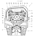
図1は本発明の一実施形態に係る空冷式内燃機関1の要部縦断面図であり、頭上カム軸型単気筒内燃機関の上部を示している。図において矢印Fは前方を指している。図において、内燃機関1の要部の外殻はシリンダブロック2、シリンダヘッド3、シリンダヘッドカバー4から成る。シリンダブロック2の中でピストン5が上下運動をする、シリンダヘッド3の下面側に燃焼室6が形成されている。シリンダヘッド3には燃焼室6につながる排気ポート7と吸気ポート9が形成されている。排気ポート7の内側端にはこの通路を開閉する排気弁8が設けてある。排気ポート7の外側端には図示省略した排気管が連なっている。また、吸気ポート9の内側端にはこの通路を開閉する吸気弁10が設けてある。吸気ポート9の外側端には図示省略した気化器が連なっている。
FIG. 1 is a longitudinal sectional view of a main part of an air-cooled internal combustion engine 1 according to an embodiment of the present invention, and shows an upper part of an overhead camshaft type single cylinder internal combustion engine. In the figure, the arrow F points to the front. In the figure, the outer shell of the main part of the internal combustion engine 1 comprises a
排気弁8はシリンダヘッド3の前寄りにその軸部8aが前傾するように設けられ、軸部8aの上部突出部には排気弁8を閉じ方向へ付勢する弁ばね11が装着されている。吸気弁10はシリンダヘッド3の後寄りにその軸部10aが後傾するように設けられ、軸部10aの上部突出部には吸気弁10を閉じ方向へ付勢する弁ばね12が装着されている。
The exhaust valve 8 is provided on the front side of the
シリンダヘッド3とシリンダヘッドカバー4とによって動弁室13が形成され、ここに前記排気弁8と吸気弁10とを開閉する動弁機構が収容されている。排気弁8と吸気弁10とで形成されるV字形の空間に、内燃機関1の前後方向に対して直交する左右方向のカム軸14がシリンダヘッド3に固定されたカム軸ホルダ41に回転可能に支持されている。このカム軸14に排気弁8を開閉駆動する排気用カム15と、吸気弁10を開閉駆動する吸気用カム16が形成されている。
A
排気弁8の上方には排気用ロッカーアーム17が排気用ロッカーアーム軸18に揺動可能に支持され、その一端はタペット19を介して排気弁の軸部8aの上端に接し、他端はローラ軸20に支持された排気用ローラ21を介して排気用カム15に接している。吸気弁10の上方には吸気用ロッカーアーム22が吸気用ロッカーアーム軸23に揺動可能に支持され、その一端はタペット24を介して吸気弁の軸部10aの上端に接し、他端はローラ軸25に支持された吸気用ローラ26を介して吸気用カム16に接している。
An
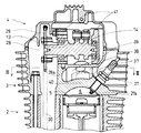
図2は上記内燃機関1の要部の横断面を後方から見た図である。図において、シリンダヘッド3には、その右側部に点火プラグ27が装着され、その先端の電極27aは燃焼室6内に突出している。また、カム軸14の一端はチェーン室28内に突出しており、その突出端には従動スプロケット29が固定されている。クランク軸には駆動スプロケット(図示なし)が固定され、チェーン室28の中で、上記駆動スプロケットと従動スプロケット29との間にカムチェーン30が掛け回されている。クランク軸が回転した時、カムチェーン30を介してカム軸14が回転駆動される。
FIG. 2 is a rear cross-sectional view of the main part of the internal combustion engine 1. In the figure, the
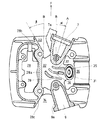
図3は図2のIII−III断面図であり、上記内燃機関のシリンダヘッドの水平断面を表している。図には、点火プラグ27を取り外し、点火プラグ取付部31が露出した状態が示してある。矢印Fは前方を指している。チェーン室28の中央部側壁28aのシリンダヘッド中央側に沿って、シリンダヘッドを前後方向に貫通する前後方向冷却風通路32が形成されている。チェーン室前部側壁28bと排気ポート周壁7aとに挟まれた空間が前方開口33、チェーン室後部側壁28cと吸気ポート周壁9aとに挟まれた空間が後方開口34である。さらに、上記前後方向冷却風通路32に連通し、排気ポート周壁7aと吸気ポート周壁9aの間を通り、内燃機関の側方へ抜ける横方向冷却風通路35が形成されている。点火プラグ取付部31の両脇の外方が側方開口36である。更に、図に示されるように、排気ポート7の中心線Aを内燃機関の前後方向線Bに対して前方開口33を広げる方向へ角αだけ傾斜させ、かつ、チェーン室前部側壁28bを、内燃機関前後方向線Bに対して角βだけ傾斜させて、前方開口33の開口面積を大きくし、冷却風通路に多量の空気を導入するようにしてある。
FIG. 3 is a cross-sectional view taken along the line III-III of FIG. The figure shows a state where the
前後方向冷却風通路32と横方向冷却風通路35との接続部、および横方向冷却風通路35の中に、3枚の冷却フィンが形成されている。前フィン37、中フィン38、後フィン39である。図の中フィン38、後フィン39のハッチングを付してある部分は、補強のために厚くしてある肉厚背高部であり、その頂部は、冷却風通路の天井につながっている。
Three cooling fins are formed in the connecting portion between the front-rear direction
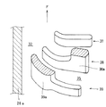
図4は、上記冷却フィンを後方の斜め上方から見た斜視図である。中フィン38、後フィン39の頂部のハッチングを付してある部分は、冷却風通路の天井につながっている肉厚背高部38a、39aの頂部の断面である。なお、図1には、横方向冷却風通路35内に3枚のフィンの縦断面が描いてある。図2には、冷却風通路に設けてある上記の3枚のフィンを内燃機関後方から見たように描いてある。
FIG. 4 is a perspective view of the cooling fin as viewed obliquely from the rear. The hatched portions of the
本実施形態の空冷式内燃機関の構成は以上のとおりである。この内燃機関を搭載した自動二輪車が走行している時に走行風が生じ、この走行風が前後方向冷却風通路32の前方開口33から流入し、その一部は3枚のフィンの案内作用によって、横方向冷却風通路35を経て、点火プラグ27の両側を通過し、側方開口36から流出する。他の一部は3枚のフィンの間を通り抜けて、前後方向冷却風通路32の後方開口34から流出する。
The configuration of the air-cooled internal combustion engine of the present embodiment is as described above. A traveling wind is generated when the motorcycle equipped with the internal combustion engine is traveling, and the traveling wind flows from the front opening 33 of the front-rear direction
車両走行中に、走行風によって、前後方向冷却風通路32および横方向冷却風通路35に面したシリンダヘッドの外壁面が冷却される。特に、燃焼室6の高温は、燃焼室頂部外殻40(図2)を経由して前、中、後のフィン37、38、39に伝達され、前後方向冷却風および横方向冷却風によって冷却される。燃焼室が効果的に冷却されることによりノッキングのタフネスが向上し、点火時期を進角できることから、燃費の向上を図ることができる。また、これらの冷却作用によって、シリンダヘッドの過熱が防止され、シリンダヘッド周辺のシール劣化が防止される。また、点火プラグ30の電極30aで生じた高温は、点火プラグ30の外方露出部に伝達され、上記の横方向冷却風によって冷却されるので、点火プラグの過熱による劣化が防止され、点火プラグの寿命が延びる。また、本発明の点火プラグは横方向冷却風通路の中に傾斜して設けてあるので、内燃機関の側部からの取り付け取り外しが容易であり、整備性が向上している。
During traveling of the vehicle, the outer wall surface of the cylinder head facing the front-rear direction cooling
更に、図3に示されるように、排気ポート7の中心線Aが内燃機関前後方向線Bに対して前方開口33を広げる方向へ角αだけ傾斜させてあるので、前方開口33の開口面積が大きくなり、多量の空気を導入することができるので、走行風による空冷の効果が大きい。
Further, as shown in FIG. 3, the center line A of the
1…空冷式内燃機関、2…シリンダブロック、3…シリンダヘッド、4…シリンダヘッドカバー、5…ピストン、6…燃焼室、7…排気ポート、7a…排気ポート周壁、8…排気弁、9…吸気ポート、9a…吸気ポート周壁、10…吸気弁、11…弁ばね、、12…弁ばね、13…動弁室、14…カム軸、15…排気用カム、16…吸気用カム、17…排気用ロッカーアーム、18…排気用ロッカーアーム軸、19…タペット、20…ローラ軸、21…排気用ローラ、22…吸気用ロッカーアーム、23…吸気ロッカーアーム軸、24…タペット、25…ローラ軸、26…吸気用ローラ、27…点火プラグ、27a…電極、28…チェーン室、28a…チェーン室中央部側壁、28b…チェーン室前部側壁、28c…チェーン室後部側壁、29…従動スプロケット、30…カムチェーン、31…点火プラグ取付部、32…前後方向冷却風通路、33…前方開口、34…後方開口、35…横方向冷却風通路、36…側方開口、37…前フィン、38…中フィン、38a…中フィンの肉厚背高部、39…後フィン、39a…後フィンの肉厚背高部、40…燃焼室頂部外殻、41…カム軸ホルダ。
DESCRIPTION OF SYMBOLS 1 ... Air-cooled internal combustion engine, 2 ... Cylinder block, 3 ... Cylinder head, 4 ... Cylinder head cover, 5 ... Piston, 6 ... Combustion chamber, 7 ... Exhaust port, 7a ... Exhaust port peripheral wall, 8 ... Exhaust valve, 9 ...
Claims (3)
前記燃焼室と前記動弁機構との間で、前後に配置された排気ポートと吸気ポートとに沿って前後方向冷却風通路を設けて、自動二輪車に搭載された空冷式内燃機関において、
前記動弁機構のチェーン室をシリンダヘッド側方に配置し、
前記前後方向冷却風通路の一方の側部を前記チェーン室側壁により構成するとともに、前記前後方向冷却風通路の他方の側部を前記排気ポートの周壁と前記吸気ポートの周壁とにより構成し、
前記前後方向冷却風通路の前方開口を前方に向って広げるよう、前記排気ポート中心線の前部が前記チェーン室から離れる方向へ該排気ポート中心線を傾斜させ、
前記排気ポートと前記吸気ポートとの間に、前記前後方向冷却風通路に連通する横方向冷却風通路を設け、
同横方向冷却風通路に点火プラグを設けるとともに、
前記前後方向冷却風通路から前記横方向冷却風通路に向かって湾曲する冷却フィンを設けことを特徴とする空冷式内燃機関。 A valve mechanism is installed at the top of the combustion chamber,
In the air-cooled internal combustion engine mounted on the motorcycle, a front-rear direction cooling air passage is provided between the combustion chamber and the valve mechanism along the exhaust port and the intake port arranged in the front-rear direction.
The chain chamber of the valve mechanism is arranged on the side of the cylinder head,
One side portion of the front-rear direction cooling air passage is constituted by the chain chamber side wall, and the other side portion of the front-rear direction cooling air passage is constituted by the peripheral wall of the exhaust port and the peripheral wall of the intake port,
Inclining the exhaust port center line in a direction in which the front portion of the exhaust port center line is away from the chain chamber so as to widen the front opening of the front-rear cooling air passage toward the front,
Between the exhaust port and the intake port is provided with a lateral cooling air passage communicating with the longitudinal direction the cooling air passage,
While providing a spark plug in the transverse cooling air passage,
An air-cooled internal combustion engine comprising cooling fins that curve from the front-rear cooling air passage toward the lateral cooling air passage.
Priority Applications (1)
| Application Number | Priority Date | Filing Date | Title |
|---|---|---|---|
| JP2003332354A JP4265764B2 (en) | 2002-09-24 | 2003-09-24 | Air-cooled internal combustion engine |
Applications Claiming Priority (2)
| Application Number | Priority Date | Filing Date | Title |
|---|---|---|---|
| JP2002276924 | 2002-09-24 | ||
| JP2003332354A JP4265764B2 (en) | 2002-09-24 | 2003-09-24 | Air-cooled internal combustion engine |
Publications (2)
| Publication Number | Publication Date |
|---|---|
| JP2004138053A JP2004138053A (en) | 2004-05-13 |
| JP4265764B2 true JP4265764B2 (en) | 2009-05-20 |
Family
ID=32473038
Family Applications (1)
| Application Number | Title | Priority Date | Filing Date |
|---|---|---|---|
| JP2003332354A Expired - Lifetime JP4265764B2 (en) | 2002-09-24 | 2003-09-24 | Air-cooled internal combustion engine |
Country Status (1)
| Country | Link |
|---|---|
| JP (1) | JP4265764B2 (en) |
Families Citing this family (5)
| Publication number | Priority date | Publication date | Assignee | Title |
|---|---|---|---|---|
| JP5479965B2 (en) * | 2010-03-23 | 2014-04-23 | 本田技研工業株式会社 | Spark plug cooling device for vehicle engine |
| JP5415363B2 (en) * | 2010-06-11 | 2014-02-12 | 本田技研工業株式会社 | Cylinder head structure of internal combustion engine |
| JP5719657B2 (en) * | 2011-03-29 | 2015-05-20 | 本田技研工業株式会社 | Saddle riding vehicle |
| JP5771494B2 (en) * | 2011-09-28 | 2015-09-02 | 本田技研工業株式会社 | Variable valve operating device for internal combustion engine |
| JP6851409B2 (en) * | 2019-02-26 | 2021-03-31 | 本田技研工業株式会社 | Internal combustion engine for saddle-type vehicles |
-
2003
- 2003-09-24 JP JP2003332354A patent/JP4265764B2/en not_active Expired - Lifetime
Also Published As
| Publication number | Publication date |
|---|---|
| JP2004138053A (en) | 2004-05-13 |
Similar Documents
| Publication | Publication Date | Title |
|---|---|---|
| JP4244178B2 (en) | Cylinder head cooling air passage structure | |
| CN100582453C (en) | Internal combustion engine for vehicle | |
| EP1403496B1 (en) | Air-cooled internal combustion engine | |
| CN101111669B (en) | internal combustion engine | |
| JP5345405B2 (en) | Cylinder head cooling structure | |
| JPS6243050B2 (en) | ||
| JP4265764B2 (en) | Air-cooled internal combustion engine | |
| CN101080566B (en) | Internal combustion engine for vehicle | |
| JPWO2017154782A1 (en) | Intake structure of internal combustion engine | |
| JP4602235B2 (en) | Internal combustion engine and motorcycle | |
| JP5415363B2 (en) | Cylinder head structure of internal combustion engine | |
| JP7236267B2 (en) | Air-cooled engine for straddle-type vehicle | |
| JP2000205042A (en) | Multi-cylinder engine | |
| CN100532150C (en) | Air guide structure for vehicle internal combustion engine | |
| JP6262168B2 (en) | In-cylinder injection internal combustion engine of saddle riding type vehicle | |
| JP2024025032A (en) | Oil passage arrangement structure of internal combustion engine | |
| JP2001193553A (en) | Intake device for engine | |
| EP4495397B1 (en) | Installation structure for air control device | |
| JPH11153029A (en) | Motorcycle engine | |
| CN111608817B (en) | Saddle-ride type internal combustion engine for vehicle | |
| JP4795905B2 (en) | Water-cooled engine | |
| JP2008075507A (en) | Water-cooled multi-cylinder engine | |
| JPS61167107A (en) | Overhead camshaft type engine | |
| KR100798580B1 (en) | Automotive Internal Combustion Engine | |
| JPH0441241Y2 (en) |
Legal Events
| Date | Code | Title | Description |
|---|---|---|---|
| A621 | Written request for application examination |
Free format text: JAPANESE INTERMEDIATE CODE: A621 Effective date: 20051201 |
|
| A131 | Notification of reasons for refusal |
Free format text: JAPANESE INTERMEDIATE CODE: A131 Effective date: 20081118 |
|
| A977 | Report on retrieval |
Free format text: JAPANESE INTERMEDIATE CODE: A971007 Effective date: 20081120 |
|
| A521 | Request for written amendment filed |
Free format text: JAPANESE INTERMEDIATE CODE: A523 Effective date: 20090119 |
|
| TRDD | Decision of grant or rejection written | ||
| A01 | Written decision to grant a patent or to grant a registration (utility model) |
Free format text: JAPANESE INTERMEDIATE CODE: A01 Effective date: 20090210 |
|
| A01 | Written decision to grant a patent or to grant a registration (utility model) |
Free format text: JAPANESE INTERMEDIATE CODE: A01 |
|
| A61 | First payment of annual fees (during grant procedure) |
Free format text: JAPANESE INTERMEDIATE CODE: A61 Effective date: 20090210 |
|
| R150 | Certificate of patent or registration of utility model |
Ref document number: 4265764 Country of ref document: JP Free format text: JAPANESE INTERMEDIATE CODE: R150 Free format text: JAPANESE INTERMEDIATE CODE: R150 |
|
| FPAY | Renewal fee payment (event date is renewal date of database) |
Free format text: PAYMENT UNTIL: 20120227 Year of fee payment: 3 |
|
| FPAY | Renewal fee payment (event date is renewal date of database) |
Free format text: PAYMENT UNTIL: 20130227 Year of fee payment: 4 |
|
| FPAY | Renewal fee payment (event date is renewal date of database) |
Free format text: PAYMENT UNTIL: 20130227 Year of fee payment: 4 |
|
| FPAY | Renewal fee payment (event date is renewal date of database) |
Free format text: PAYMENT UNTIL: 20140227 Year of fee payment: 5 |
|
| EXPY | Cancellation because of completion of term |