JP4265720B2 - Hemodiafiltration machine - Google Patents
Hemodiafiltration machine Download PDFInfo
- Publication number
- JP4265720B2 JP4265720B2 JP2000096666A JP2000096666A JP4265720B2 JP 4265720 B2 JP4265720 B2 JP 4265720B2 JP 2000096666 A JP2000096666 A JP 2000096666A JP 2000096666 A JP2000096666 A JP 2000096666A JP 4265720 B2 JP4265720 B2 JP 4265720B2
- Authority
- JP
- Japan
- Prior art keywords
- dialysate
- blood
- supply
- flow path
- channel
- Prior art date
- Legal status (The legal status is an assumption and is not a legal conclusion. Google has not performed a legal analysis and makes no representation as to the accuracy of the status listed.)
- Expired - Lifetime
Links
- 239000008280 blood Substances 0.000 claims description 160
- 210000004369 blood Anatomy 0.000 claims description 160
- 239000007788 liquid Substances 0.000 claims description 88
- 239000012530 fluid Substances 0.000 claims description 58
- 230000036772 blood pressure Effects 0.000 claims description 50
- 230000007246 mechanism Effects 0.000 claims description 46
- 238000001914 filtration Methods 0.000 claims description 29
- 230000009471 action Effects 0.000 claims description 26
- 239000012528 membrane Substances 0.000 claims description 26
- 230000017531 blood circulation Effects 0.000 claims description 19
- 238000000746 purification Methods 0.000 claims description 17
- 238000001631 haemodialysis Methods 0.000 claims description 16
- 230000000322 hemodialysis Effects 0.000 claims description 16
- XLYOFNOQVPJJNP-UHFFFAOYSA-N water Substances O XLYOFNOQVPJJNP-UHFFFAOYSA-N 0.000 claims description 15
- 238000000502 dialysis Methods 0.000 claims description 13
- 239000000243 solution Substances 0.000 claims description 11
- 238000006467 substitution reaction Methods 0.000 claims description 10
- 208000024891 symptom Diseases 0.000 claims description 9
- 239000000385 dialysis solution Substances 0.000 claims description 7
- 238000007599 discharging Methods 0.000 claims description 6
- 230000008859 change Effects 0.000 claims description 2
- 238000011403 purification operation Methods 0.000 description 30
- 238000000034 method Methods 0.000 description 7
- 230000009467 reduction Effects 0.000 description 7
- 230000036770 blood supply Effects 0.000 description 6
- 238000011026 diafiltration Methods 0.000 description 5
- 238000011144 upstream manufacturing Methods 0.000 description 5
- 238000010586 diagram Methods 0.000 description 4
- 238000001514 detection method Methods 0.000 description 3
- 239000000126 substance Substances 0.000 description 3
- 238000002615 hemofiltration Methods 0.000 description 2
- 239000000463 material Substances 0.000 description 2
- 238000010572 single replacement reaction Methods 0.000 description 2
- 238000000108 ultra-filtration Methods 0.000 description 2
- QGZKDVFQNNGYKY-UHFFFAOYSA-O Ammonium Chemical compound [NH4+] QGZKDVFQNNGYKY-UHFFFAOYSA-O 0.000 description 1
- 229920000297 Rayon Polymers 0.000 description 1
- 208000001647 Renal Insufficiency Diseases 0.000 description 1
- XSQUKJJJFZCRTK-UHFFFAOYSA-N Urea Chemical compound NC(N)=O XSQUKJJJFZCRTK-UHFFFAOYSA-N 0.000 description 1
- LEHOTFFKMJEONL-UHFFFAOYSA-N Uric Acid Chemical compound N1C(=O)NC(=O)C2=C1NC(=O)N2 LEHOTFFKMJEONL-UHFFFAOYSA-N 0.000 description 1
- TVWHNULVHGKJHS-UHFFFAOYSA-N Uric acid Natural products N1C(=O)NC(=O)C2NC(=O)NC21 TVWHNULVHGKJHS-UHFFFAOYSA-N 0.000 description 1
- 239000004202 carbamide Substances 0.000 description 1
- 229920002678 cellulose Polymers 0.000 description 1
- 239000001913 cellulose Substances 0.000 description 1
- 238000012937 correction Methods 0.000 description 1
- 230000003247 decreasing effect Effects 0.000 description 1
- 230000006866 deterioration Effects 0.000 description 1
- 238000009792 diffusion process Methods 0.000 description 1
- 238000003113 dilution method Methods 0.000 description 1
- 230000000694 effects Effects 0.000 description 1
- 239000012510 hollow fiber Substances 0.000 description 1
- 201000006370 kidney failure Diseases 0.000 description 1
- 239000006166 lysate Substances 0.000 description 1
- 238000012423 maintenance Methods 0.000 description 1
- 229920002239 polyacrylonitrile Polymers 0.000 description 1
- 238000005086 pumping Methods 0.000 description 1
- 239000002964 rayon Substances 0.000 description 1
- 238000011084 recovery Methods 0.000 description 1
- 230000004044 response Effects 0.000 description 1
- 230000006641 stabilisation Effects 0.000 description 1
- 238000011105 stabilization Methods 0.000 description 1
- 230000000087 stabilizing effect Effects 0.000 description 1
- 230000001954 sterilising effect Effects 0.000 description 1
- 238000004659 sterilization and disinfection Methods 0.000 description 1
- 229940116269 uric acid Drugs 0.000 description 1
Images

Landscapes
- External Artificial Organs (AREA)
Description
【0001】
【技術分野】
本発明は、血液透析濾過装置に係り、特に血液の透析・濾過からなる浄化操作中における患者の血圧低下(降下)に対して、浄化操作の停止を伴なうことなく、効果的に対処し得る血液透析濾過装置に関するものである。
【0002】
【背景技術】
従来から、腎不全の患者の治療や生命の維持等のために、患者の体内から取り出した血液を浄化して、再び体内に戻すようにした血液浄化手法が種々検討されて、実用化されてきており、そこでは、一般に、函体内に中空繊維状のセルロース膜、キュプラアンモニウムレーヨン膜、ポリアクリロニトリル膜等の半透膜を収容した浄化器としての透析器(ダイアライザー)が用いられ、例えば血液透析法(HD)の場合には、そのような透析器の半透膜を介して血液と透析液を接触せしめ、拡散による物質の移動によって、患者の血液中に蓄積した尿素、尿酸等を除去せしめており、また血液濾過法(HF)の場合には、かかる半透膜に存在する膜孔を通じての濾過操作によって、血液中の不要或いは有害な物質を通過、除去せしめるようにしており、更に血液透析濾過( Hemodiafiltration :HDF)法の場合には、そのような血液透析と血液濾過を同時併用して、血液浄化を行なうようにしているのである。
【0003】
また、そのような血液浄化操作のうちの、血液透析濾過法を行なうための装置としては、例えば特公昭56−35496号公報等に明らかにされている如く、函体内に半透膜を収容してなる血液浄化器を用い、かかる半透膜を介して血液を透析液に接触せしめるようにする一方、そのような血液浄化器に供給される透析液の供給量とそれから排出される透析液量を調節することによって、かかる血液浄化器内において、血液透析と血液濾過とが同時に行なわれ得るようにすると共に、透析液を血液浄化器に流すための透析液回路から、血液を血液浄化器に流すための血液回路に、所定量の透析液が、置換液乃至は置換補充液として供給せしめられるように為して、血液浄化器における血液濾過量を補償するようにした構造の装置が、明らかにされている。
【0004】
ところで、かくの如き従来からの血液浄化手法にあっては、その血液浄化操作中において、患者が血圧低下(降下)を来す場合があり、それによって、血液浄化操作の停止を余儀なくされる問題があった。そして、そのような血圧低下の要因については、従来から種々なる検討が行なわれているが、また血液浄化手法の如何によっても異なり、例えば、血液濾過操作の場合には、血圧が安定しているのに対して、血液透析操作や血液透析濾過操作の場合においては、血圧低下が惹起されることが知られている。
【0005】
特に、近年においては、血液浄化操作を受ける患者の年齢が一段と高くなってきているところから、その血液浄化操作中における血圧低下が惹起され易くなっているのであり、それ故に、そのような血圧低下が予測されたり或いは現実に発生したりした場合には、そのような血液浄化操作を続行しつつ、早急に適切な処置を施し、血圧低下の阻止乃至は血圧の安定化を図り、更には血圧の回復を図ることが望まれるのである。
【0006】
【解決課題】
ここにおいて、本発明は、かかる事情を背景にして為されたものであって、その解決課題とするところは、血液の透析濾過中において、血圧低下が惹起されても、その更なる進行を阻止して、少なくとも血圧の安定化を図り、以て血液浄化操作をそのまま続行せしめ得るようにした血液透析濾過装置を提供することにある。
【0007】
【解決手段】
そして、そのような課題を解決するために、本発明にあっては、函体内に半透膜を収容し、該半透膜を介して血液を透析液に接触せしめて透析し、また濾過して、血液を浄化するようにした血液浄化器と、該血液浄化器に血液を流通せしめるための血液流路と、該血液浄化器に透析液を供給する透析液の供給流路と、該血液浄化器から透析液を排出せしめる透析液の排出流路と、それら透析液供給流路と血液流路とを接続する置換液供給流路と該置換液供給流路上に設けられた置換液浄化手段と置換液送液手段とからなる、該透析液供給流路から導かれる所定量の透析液を浄化せしめて置換液として該血液流路に給送する置換液供給機構と、前記透析液の供給流路及び排出流路上に設けられ、透析液の該供給流路における入口流量と該排出流路における出口流量とを同時に調節し、その差を体内よりの除水量と等しくする透析液の流入及び流出量調節機構とを含む血液透析濾過装置において、前記透析液の流入及び流出量調節機構における前記透析液供給流路への透析液の入口流量と、前記置換液供給流路上に設けられた前記置換液送液手段における置換液としての透析液の吐出量との差を調節する制御装置を設け、かかる制御装置によって、前記血液浄化器における血液透析作用と血液濾過作用の比率を変化させ得るようにしたことを特徴とする血液透析濾過装置を、その要旨とするものである。
【0008】
すなわち、このような本発明に従う血液透析濾過装置にあっては、透析液の流入及び流出量調節機構による透析液供給流路の入口流量と置換液送液手段の吐出量との差を調節する制御装置によって、血液の透析濾過中における血圧低下が予想される場合や現実に血圧低下が惹起された場合等において、かかる透析液供給流路の入口流量と置換液送液手段における吐出量との差を小さくならしめ、以て血液浄化器における血液透析作用を低下させることによって、血液浄化器における血液浄化が主として血液濾過作用にて行なわれ得るようにすることにより、血圧低下の効果的な抑制、更には阻止を図り、また血圧の安定化を図って、そのまま、血液浄化操作が続行せしめられ得るようになっているのであり、また、それによって血圧が再上昇或いは安定した場合には、上記制御装置によって、透析液供給流路の入口流量と置換液送液手段の吐出量との差を大ならしめ、以て血液浄化器における血液透析作用を再び増大させることが出来るようにもなっているのである。
【0009】
また、本発明は、函体内に半透膜を収容し、該半透膜を介して血液を透析液に接触せしめて透析し、また濾過して、血液を浄化するようにした血液浄化器と、該血液浄化器に血液を流通せしめるための血液流路と、該血液浄化器に透析液を供給する透析液の供給流路と、該血液浄化器から透析液を排出せしめる透析液の排出流路と、それら透析液供給流路と血液流路とを接続する置換液供給流路上に設けられた置換液送液手段と置換液浄化手段によって、該透析液供給流路から導かれる所定量の透析液を浄化せしめて、置換液として該血液流路に給送する置換液供給機構と、前記透析液の供給流路及び排出流路上に設けられ、透析液の該供給流路における入口流量と該排出流路における出口流量とを同時に調節し、その差を体内よりの除水量と等しくする透析液の流入及び流出量調節機構とを含む血液透析濾過装置において、前記透析液の流入及び流出量調節機構における前記透析液供給流路への透析液の入口流量と、前記置換液供給流路上に設けられた前記置換液送液手段における置換液としての透析液の吐出量との差を調節する制御装置を設け、かかる制御装置によって、該透析液の入口流量を前記置換液送液手段における吐出量に近付けるように変化せしめることにより、前記血液浄化器における血液透析作用を低下させて、該血液浄化器において主として血液濾過操作が進行せしめられ得るようにしたことを特徴とする血液透析濾過装置をも、その要旨とするものである。
【0010】
なお、上記せる如き本発明に従う血液透析濾過装置の好ましい態様の一つによれば、前記制御装置によって、前記入口流量と前記吐出量との差が0〜200mL/分まで低下するように、制御され得るようになっており、これにより、血液浄化器内における血液浄化操作を、血液濾過操作に近付け、以て有効な血圧低下の抑制乃至は阻止、更には血圧の安定化を図り得るようになっている。
【0011】
また、本発明における別の好ましい態様によれば、前記制御装置による、前記透析液供給流路への透析液の入口流量と前記血液流路への置換液としての透析液の吐出量との差の制御を、患者の血圧及び/又は症状についての情報に基づいて、自動的に行なう機構、若しくはかかる制御を、蓄積された患者の過去の透析中における血圧及び/又は症状に関する情報に基づいて、時系列的に且つ自動的に行なう機構を備えて構成されるのであり、これによって、患者の一人一人に応じた適切な血液浄化操作が有利に実現され得ることとなる。
【0012】
さらに、本発明の望ましい他の態様によれば、前記透析液の流入及び流出量調節機構は、前記透析液供給流路における透析液の流量と前記透析液排出流路における透析液の流量とを同一と為す流量同一化機構と、該透析液供給流路に透析液を送液せしめる透析液送液ポンプ手段とを含んで構成されており、或いは前記透析液供給流路における透析液の流量と前記透析液排出流路における透析液の流量とを同一化すると共に、少なくとも該透析液供給流路に透析液を送液せしめる流量同一化・送液ポンプ機構を含んで構成されており、それら透析液送液ポンプ手段や流量同一化・送液ポンプ機構が、本発明に従って制御装置にて制御せしめられることによって、透析液供給流路に送液される透析液量が制御されるようになっているのである。
【0013】
更にまた、本発明にあっては、好ましくは、複数の患者の個別の血液透析濾過操作のために、前記血液浄化器の複数が配置されて、それら複数の血液浄化器に対して、前記血液流路及び前記透析液供給流路、透析液排出流路がそれぞれ設けられてなると共に、それぞれの血液浄化器における血液流路と透析液供給流路とを接続する置換液供給流路が各血液浄化器毎に設けられ、そしてそれら複数の置換液供給流路が一つの置換液浄化手段を経て、それぞれの血液流路に接続されて、各血液流路に導かれる置換液としての透析液が該一つの置換液浄化手段にてそれぞれ浄化せしめられるようにした構成が、有利に採用される。
【0014】
この構成では、複数の患者の血液透析濾過操作において、それぞれの置換液供給流路に設けられる置換液浄化手段が一つで済むこととなり、全体としての血液浄化操作のコスト低減が効果的に為され得るのである。
【0015】
なお、かかる複数の患者の個別の血液透析濾過操作のための装置において、望ましくは、前記複数の置換液供給流路の各々に、前記置換液浄化手段よりも上流側の流路における置換液流量と下流側の流路における置換液流量とが同一となるように、前記血液流路に送液せしめる流量同一化・送液ポンプ手段が、前記置換液送液手段としてそれぞれ設けられている構成が、有利に採用されることとなる。
【0016】
【発明の実施の形態】
以下に、本発明の構成をより具体的に明らかにするために、本発明に係る血液透析濾過装置の代表的な具体例について、図面に基づいて詳細に説明することとする。
【0017】
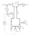
先ず、図1は、本発明に係る血液透析濾過装置の一例を示す系統図であって、そこにおいて、2は、血液浄化器としての透析器(ダイアライザー)であって、従来と同様な構造を有しており、円筒形状の函体内部に中空繊維状の半透膜が収容されている。そして、そのような透析器2の軸方向の一端側には、患者の体内から血液を導くための血液供給流路4が接続され、また他端側には、透析器2において、浄化(透析濾過)された血液を患者の体内に戻すための血液返送流路6が接続されている。このように、ここでは、血液供給流路4と血液返送流路6によって、血液流路が構成されている一方、血液供給流路4上には、血液ポンプ8が設けられ、この血液ポンプ8の作動によって、血液流路や透析器2内に血液が流通せしめられるようになっている。
【0018】
また、透析器2には、透析液をその貯槽(図示せず)より透析器2内に導くための透析液供給流路10が接続されており、更に、かかる透析器2において半透膜を介して血液に接触せしめられた透析液を排出し、また半透膜を通じて血液側から濾過された濾過物質(排液)を排出するための透析液排出流路12が設けられている。なお、ここでは、それら透析液供給流路10と透析液排出流路12とによって、透析液流路が構成されている。
【0019】
そして、かかる透析液供給流路10と透析液排出流路12の流路上には、ダブルプランジャポンプ14が設けられており、このダブルプランジャポンプ14が駆動装置16によって、図中、矢印にて示される如く、往復駆動せしめられることにより、透析液供給流路10に供給せしめられる透析液の流量と透析液排出流路12を通じて排出せしめられる透析液流量とが同一となるように構成されている。即ち、ここでは、かかるダブルプランジャポンプ14と駆動装置16とは、流量同一化・送液ポンプ機構を構成しており、ダブルプランジャポンプの一方のプランジャポンプ部の吸引・吐出量と他方のプランジャポンプ部の吸引・吐出量とが、同一となるように構成されているのである。なお、図示はされていないが、ダブルプランジャポンプ14の透析液供給流路10上に配置されたプランジャポンプ部の吸引側と吐出側には、それぞれ逆止弁が設けられており、かかるプランジャポンプ部のポンプ作動によって、透析液が透析器2側に供給されるようになっており、またダブルプランジャポンプ14の透析液排出流路12上に配置されたプランジャポンプ部の吸引側と吐出側には、それぞれ逆止弁が設けられており、かかるプランジャポンプ部のポンプ作動によって、透析器2から排出される透析液が系外に流出せしめられるようになっている。
【0020】
また、かかるダブルプランジャポンプ14と透析器2との間の透析液排出流路12に対して、分岐流路18が接続され、この分岐流路18上に、除水ポンプ20が設けられており、この除水ポンプ20の駆動によって、透析器2による血液透析濾過に際して、患者の体内より所定量の除水が行なわれ得るようになっている。従って、ここでは、前記したダブルプランジャポンプ14と駆動装置16と共に、かかる除水ポンプ20によって、本発明における透析液の流入及び流出量調節機構が構成されているのである。
【0021】
さらに、置換液供給流路22が、ダブルプランジャポンプ14と透析器2との間の透析液供給流路10と血液返送流路6とを接続するように設けられており、この置換液供給流路22上に配置した置換液送液手段としての置換液ポンプ24のポンプ作動によって、透析液供給流路10から、置換液フィルタ26を通じて、透析液が置換液として血液返送流路6に供給されて、体内に返送せしめられる血液に混入せしめられるようになっている。そして、これに伴って、透析器2における血液濾過量が置換液ポンプ24による吐出量の分だけ増大することとなる。なお、置換液フィルタ26は、置換液として血液返送流路6に供給せしめられる透析液を浄化するための置換液浄化手段として機能するものであって、透析器2と同様に、フィルム状、チューブ状或いは中空繊維状の半透膜を収容した容器から構成され、そのような半透膜を透析液が通過せしめられることにより、その浄化が行なわれ得るようになっているのである。
【0022】
そして、かかる置換液供給流路22上に配置された置換液ポンプ24の作動とダブルプランジャポンプ14を駆動せしめる駆動装置16の作動とが、制御装置30にて制御されて、そのような置換液ポンプ24における置換液としての透析液の吐出量とダブルプランジャポンプ14における透析液供給流路10への透析液の入口流量との差が調節され得るようになっているのであり、また、そのような制御装置30によって、除水ポンプ20の吐出量を考慮して、駆動装置16の作動制御を行ない、ダブルプランジャポンプ14の一方のプランジャポンプ部からの透析液供給流路10への透析液の供給量(入口流量)を低下せしめることにより、かかる透析液の供給量を置換液ポンプ24における吐出量に近付けるように変化せしめて、透析器2への透析液供給量を低下せしめ、以て透析器2における血液透析作用を低下させる一方、そのような透析器2における血液濾過作用はそのまま維持し得るようになっているのである。
【0023】
従って、かくの如き構造の血液透析濾過装置を用いた血液の透析・濾過を行なう定常の血液浄化操作においては、従来と同様に、透析器2に対して、血液ポンプ8により、血液供給流路4及び血液返送流路6からなる血液流路を通じて、所定量の血液が流通せしめられる一方、駆動装置16にて駆動せしめられるダブルプランジャポンプ14の一方のプランジャポンプ部の吸引・吐出作動(ポンプ作動)によって、透析液供給流路10に対して、所定量(例えば400〜500mL/分程度)の透析液が供給せしめられ、また、そのような透析液供給量と同量の透析液(濾過物質を含む)が、ダブルプランジャポンプ14の他方のプランジャポンプ部のポンプ作動にて、透析液排出流路12を通じて系外に排出されるようになっていると共に、透析液排出流路12には、分岐流路18上に設けた除水ポンプ20のポンプ作動により、目的とする体内よりの除水量に等しい量(例えば10mL/分程度)の透析液が、系外に排出せしめられるようになっているのである。
【0024】
また、透析液供給流路10と血液返送流路6とをつなぐ置換液供給流路22を通じて、透析液供給流路10から導かれた透析液が、置換液ポンプ24のポンプ作動にて、所定の割合(例えば60mL/分程度)において、血液返送流路6に供給されるようになっているところから、透析器2には、透析液供給流路10を通じて、ダブルプランジャポンプ14からの透析液の供給量から置換液ポンプ24の吐出量を減じた量の透析液が供給せしめられて、かかる透析器2内に収容せしめた半透膜を介して、血液に対する透析作用が行なわれると共に、透析液排出流路12を通じて、ダブルプランジャポンプ14による透析液の排出量に除水ポンプ20による除水量を加えた分の透析液(濾過物質を含む)が系外に排出されることとなるところから、透析器2においては、供給透析液量よりも排出透析液量の方が多くなるのであり、従って半透膜を通じての限外濾過作用によって、血液の濾過操作が、前記した透析操作と並行して行なわれ、以て血液の浄化操作が進行せしめられるのである。
【0025】
そして、このような定常の血液透析・濾過からなる浄化操作を実施している間において、何等かの原因により、患者の血圧低下(降下)が予測されたり、或いは現実に血圧低下が生じたりすると、制御装置30によって、駆動装置16の作動が制御され、以てダブルプランジャポンプ14による透析液供給流路10への透析液の吐出量と置換液ポンプ24の吐出量との差が小さくならしめられるのであり、これによって、透析器2への透析液供給流路10を通じての透析液の供給量が低減され、究極的には、透析液の供給量が0とされることにより、透析器2においては、半透膜を介しての血液透析作用は低下せしめられる一方、透析液排出流路12を通じてのダブルプランジャポンプ14による透析液の排出作用は、その排出量が低下せしめられるとしても、0とはならないところから、少なくとも置換液ポンプ24の吐出量に見合う量において、血液の濾過作用はそのまま維持されて、透析器2内においては、血液濾過作用による血液の浄化操作が主として進行せしめられることとなるのである。
【0026】
このように、透析器2内において、血液透析よりも血液濾過を主体とした血液浄化操作が行なわれるようにすることにより、従来の血液濾過法(HF)における血液浄化操作の場合と同様に、血圧の安定化が効果的に図られ得、また血圧の低下が阻止され、更には血圧の回復も期待され得るところから、患者に対する血液浄化操作を停止させる必要がなく、そのまま血液浄化操作を続行することが出来るのである。
【0027】
なお、このような血液の透析濾過作用に基づく血液浄化操作から、血液濾過作用を主体とする血液浄化操作への切換のために、制御装置30によって、ダブルプランジャポンプ14の駆動装置16及び/又は置換液ポンプ24の作動制御が適宜に行なわれることとなるが、有利には、ダブルプランジャポンプ14による透析液供給流路10への透析液の供給量と置換液ポンプ24の吐出量との差が、一般に、0〜200mL/分となるように、好ましくは0〜100mL/分となるように、駆動装置16及び/又は置換液ポンプ24の作動が制御されて、ダブルプランジャポンプ14による透析液供給流路10への透析液の供給量と置換液ポンプ24の吐出量との差が減少せしめられることとなる。このように、ダブルプランジャポンプ14からの透析液供給流路10への透析液供給量と置換液ポンプ24の吐出量との差が低減せしめられることにより、透析器2内において、血液透析作用が低下して、患者の血圧低下の阻止乃至は安定化、更には血圧回復に、効果的に寄与せしめ得るのである。
【0028】
そして、更に、以上のような血液濾過作用を主とする血液浄化操作によって、血圧が回復乃至は上昇した場合には、制御装置30により駆動装置16の作動を制御して、ダブルプランジャポンプ14からの透析液供給流路10への透析液供給量と置換液ポンプ24の吐出量との差を増大させることで、透析器2内において、血液濾過作用に対する血液透析作用の比率(割合)を高めることが出来るのである。
【0029】
なお、上述せる如き患者の血圧に応じた血液操作を有利に実現し得る、前記制御装置30によるダブルプランジャポンプ14の駆動装置16の制御にあっては、一般に、医師や看護婦等の手動操作によって、或いは血圧検出機構等の適当な検出手段(図示せず)からの信号に基づいて実行されることとなるが、好適には、かかる検出手段にて検出される等して得られた、患者の血圧及び/又は症状についての情報に基づいて自動的に行なったり、或いはそれまでに蓄積された、患者の過去の透析中における血圧及び/又は症状に関する情報に基づいて、時系列的乃至は経時的に、且つ自動的に行なうようにすることが望ましい。これによって、患者の一人一人にきめ細かく対応した血液浄化操作が実現可能となるのである。
【0030】
また、かかる図1に示される構造の血液透析濾過装置の他にも、本発明にあっては、図2に示される如き、透析液の流入及び流出量調節機構を備えた構造の血液透析濾過装置を採用することも、可能である。
【0031】
すなわち、かかる図2に示される例においては、透析液供給流路10上と透析液排出流路12上に、それぞれ、流入・流出変換器32a、32bが配置され、それら流入・流出変換器32a、32b内が、それぞれ、ダイアフラム34a、34bにて、左右二つのチャンバに仕切られていると共に、それら流入・流出変換器32a、32bをそれぞれバイパスする供給用分岐流路36及び排出用分岐流路38が、三方弁40a、40b;40c、40dを介して、透析液供給流路10及び透析液排出流路12に対して、それぞれ、設けられているのである。そして、透析液供給流路10と供給用分岐流路36とが、流入・流出変換器32a、32bのダイアフラム34a、34bにて仕切られた一方のチャンバ(図において、左チャンバ)にそれぞれ接続せしめられ、また透析液排出流路12と排出用分岐流路38が、流入・流出変換器32a、32bのダイアフラム34a、34bにて仕切られた他方のチャンバ(図において、右チャンバ)にそれぞれ接続せしめられている。
【0032】
さらに、透析液供給流路10上には、三方弁40aの上流側と三方弁40bの下流側に位置するように、送液ポンプ42a、42bが、それぞれ、設けられ、三方弁40aの切換によって、送液ポンプ42aから送液された透析液が流入・流出変換器32a、32bの一方のチャンバに、交互に流入せしめられるようになっている一方、三方弁40bの切換によって、そのような一方のチャンバ内の透析液が、送液ポンプ42bの吸引・吐出作用にて、透析器2側の透析液供給流路10に供給せしめられるようになっている。なお、三方弁40c、40dの切換操作によって、流入・流出変換器32a、32bの他方のチャンバには、透析器2からの排出されるべき透析液が交互に流入せしめられ、そこでは、一方のチャンバに対する送液ポンプ42a、42bによる透析液の流入、吸引とは逆の流出・流入が行なわれ、三方バルブ40dを通じて、排出されるべき透析液が系外に流出せしめられ得るようになっている。
【0033】
要するに、このような機構においては、三方バルブ40aの作動によって、透析液は、透析液供給流路10と供給用分岐流路36の何れかに導かれて、それら流路上の何れかの流入・流出変換器32a又は32bの一方のチャンバ内に導き入れられる一方、他方の流入・流出変換器32b又は32aの一方のチャンバ内に収容された透析液が、三方弁40bの作動によって、透析器2側の透析液供給流路10内に導かれることとなるのであり、また、透析液排出側においては、三方弁40c、40dの切換作動によって、一方のチャンバ内に透析液が導き入れられている流入・流出変換器32a又は32bの他方のチャンバから、排出されるべき透析液が、ダイアフラム34a又は34bによる押圧作動にて排出せしめられる一方、透析液が一方のチャンバから透析器2側に導かれている流入・流出変換器32b又は32aにおいては、ダイアフラム34b又は34aの移動による吸引作用にて、かかる透析液が、流入・流出変換器32b又は32aの他方のチャンバ内に収容せしめられるようになっており、これによって、透析液供給流路10における透析液の供給量と透析液排出流路12における透析液の排出流量とが、同一化されることとなるのである。
【0034】
そして、透析液供給流路10上に設けられた二つの送液ポンプ42a及び42bの作動制御が、制御装置30にて行なわれ得るようになっているのであり、それ故に、血液浄化操作を受けている患者において、その血圧低下が予測される場合や現実に血圧低下が生じた場合等においては、制御装置30にて、二つの送液ポンプ42a、42bがそれぞれ作動制御せしめられて、置換液ポンプ24の吐出量に対して、それら送液ポンプ42a、42bの吐出量(送液量)が近付くように、それらの吐出量が低下せしめられ、以て透析器2内における血液透析作用を低下させて、血液濾過を主とする血液浄化操作が実施されるようにするのである。なお、置換液ポンプ24の吐出量は、透析器2内の半透膜の劣化(目詰まり)の進行の程度に応じて変化させるものであり、従って、二つの送液ポンプ42aと42bの吐出量の制御は、そのような置換液ポンプ24の吐出量の変化にも対応させて行なうことが、望ましい。
【0035】
従って、ここでは、二つの流入・流出変換器32a、32bと四つの三方弁40a〜40dと供給用分岐流路36、排出用分岐流路38とによって、透析液供給流路10における透析液の流量と透析液排出流路12における透析液の流量とを同一と為す流量同一化機構が構成されており、また二つの送液ポンプ42aと42bにて、透析液供給流路10に透析液を送液せしめる透析液送液ポンプ手段が構成され、更に、それら流量同一化機構と透析液送液ポンプ手段とを含み、それらと除水ポンプ20にて、透析液の流入及び流出量調節機構が構成されるようになっている。
【0036】
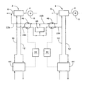
さらに、本発明にあっては、複数の患者の個別の血液透析濾過操作を同時に行ない得るように、図3に示される如き配置構成の装置(システム)とすることも、有利に採用されることとなる。
【0037】
因みに、図3においては、複数の透析器2に対して、それぞれの血液返送流路6と透析液供給流路10とを接続する複数の置換液供給流路(22)が、一つの置換液フィルタ26に接続され、この一つの置換液フィルタ26にて、浄化された透析液が、置換液として、それぞれの血液返送流路6に供給されるようになっているのである。具体的には、それぞれの置換液供給流路(22)は、上流側置換液供給流路22aと下流側置換液供給流路22bとから構成され、上流側置換液供給流路22aを通じて、透析液供給流路10から導かれた透析液が、一つの置換液フィルタ26に導かれて、浄化された後、下流側置換液供給流路22bを通じて、血液返送流路6に置換液として供給されるようになっているのであり、また、それら上流側置換液供給流路22aと下流側置換液供給流路22bにまたがって、それら二つの流路における透析液(置換液)流量が同一となるようにして、送液せしめる流量同一化・送液ポンプ46が、置換液送液手段(24)として、それぞれ、設けられているのである。
【0038】
なお、透析液供給流路10と透析液排出流路12の流路上には、透析液の供給量と排出量を調節する、公知の透析液流入及び流出量調節機構44が設けられており、かかる調節機構44によって、透析器2からの該調節機構44を介しての透析液排出流量と該透析器2への透析液の供給流量とが調節されて、その差が体内からの除水量となるように設定されている。このような透析液流入及び流出機構44は、従来から透析濾過装置に付属する装置として、よく知られているものであって、例えば、市販されているウルトラフィルトレーション・コントローラー(東レ:UFCII)やUFRコントローラーと称されるもの等を用いることが出来る。
【0039】
そして、このような透析液流入及び流出量調節機構44の作動と置換液供給流路(22a、22b)上に設けた流量同一化・送液ポンプ46の作動が、制御装置30にて制御されることにより、透析液流入及び流出量調節機構44による透析液供給流路10への透析液の供給量と前記流量同一化・送液ポンプ46の吐出量との差が0に近付くように調節せしめられ得るようになっているのであり、これにより、それぞれの透析器2における血液透析作用を低下させて、主として血液濾過による血液浄化操作が進行せしめられるようにすることによって、患者の血圧低下を阻止乃至は安定化せしめ、更には血圧回復をも為し得るようになっているのである。
【0040】
このように、それぞれの置換液供給流路(22)を通じて導かれる透析液を、一つの置換液フィルタ26にて浄化せしめて、置換液として血液返送流路6内に供給し得るようにすることにより、置換液フィルタ26の使用個数の著しい低減が図られ得ることとなるのであり、以て、複数の患者に対する透析濾過操作において、その全体としてのコスト低減が有利に図られ得ることとなるのである。
【0041】
なお、かかる図3に示される例においては、二人の患者の個別の血液透析濾過操作において、一つの置換液フィルタ26を用いたシステムが明らかにされているが、三人或いはそれ以上の患者の個別の血液透析濾過操作を、一つの置換液フィルタ26を用いて、実施するようにすることが出来ることは、言うまでもないところであり、そのような場合にあっては、それぞれの置換液供給流路(22)が、一つの置換液フィルタ26に対して、それぞれ、図3の例と同様に接続せしめられることとなる。
【0042】
以上、本発明に係る血液透析濾過装置の代表的な具体例について詳細に説明してきたが、本発明が、そのような例示の具体例についての記載によって、何等の制約をも受けるものでないことは言うまでもないところである。また、本発明には、上記の具体例の他にも、本発明の趣旨を逸脱しない限りにおいて、当業者の知識に基づいて種々なる変更、修正、改良等を加え得るものであることが、理解されるべきである。
【0043】
例えば、例示の具体例においては、何れも、透析液供給流路10内を流通せしめられる透析液を分流して、置換液として供給するための置換液供給流路22が血液流路のうちの血液返送流路6に対して接続せしめられた、所謂後希釈方式が採用されているが、そのような置換液供給流路22を、血液供給流路4に対して接続して、透析器2に供給される前の血液に対して、置換液としての透析液を混入せしめるようにした、所謂前希釈方式を採用することも可能であり、更には、それら前希釈方式と先の後希釈方式とを組み合わせた方式を採用することも、可能である。
【0044】
また、置換液供給流路22上における置換液ポンプ24と置換液フィルタ26の配置関係にあっても、例示の具体例では、置換液ポンプ24の下流側に置換液フィルタ26が配されてなる構成が採用されているが、これとは逆に、置換液ポンプ24の上流側に置換液フィルタ26を配するようにしても、何等差し支えなく、またそのような置換液フィルタ26として、半透膜を通過せしめることによる浄化方式を採用するものに限られることなく、その他の適当な滅菌浄化手段を使用することが、可能である。
【0045】
さらに、透析液の流入及び流出量調節機構として、或いはそれを構成する、上述せる如き流量同一化機構や透析液送液ポンプ手段又は流量同一化・送液ポンプ機構としても、例示のもののみに限定されるものでは決してなく、当業者の容易に利用乃至は想到し得る全ての機構乃至は構造又は装置を採用することが可能であるが、その中でも、置換液ポンプ24や除水ポンプ20としては、それぞれ、定量ポンプを用いる一方、透析液の流入及び流出量調節機構におけるダブルプランジャポンプ14や送液ポンプ42a、42bは、その吸引・吐出量が可変となるように作動制御せしめられ得る構成とされていることが、制御装置30による作動制御の上において、推奨されるものであるが、また、置換液ポンプ24を可変吐出量ポンプとして、制御装置30による作動制御によって、かかる置換液ポンプ24の吐出量を上昇せしめる一方、ダブルプランジャポンプ14や送液ポンプ42a、42b等の透析液の流入及び流出量調節機構による透析液供給流路10への透析液の供給量を低下せしめるようにすることも可能である。
【0046】
【発明の効果】
以上の説明から明らかなように、本発明に従う血液透析濾過装置にあっては、血液透析濾過操作中の患者の血圧低下が予測され、或いは現実に血圧低下が生じた場合において、制御装置によって、置換液送液手段に対する透析液流入及び流出量調節機構の作動制御を行ない、透析液供給流路への透析液の入口流量と置換液送液手段における吐出量との差を小さくならしめることにより、血液浄化器における血液透析作用を低下させて、かかる血液浄化器においては、主として、血液濾過操作が進行せしめられ得るようになっているところから、患者の血圧低下が効果的に阻止乃至は安定化され得て、血液の浄化操作を続行せしめることが出来るのであり、それ故に、従来の血圧低下にて血液浄化操作が低減或いは停止された場合における各種の問題を悉く解消せしめ得ることとなったのである。
【図面の簡単な説明】
【図1】本発明に係る血液透析濾過装置の一例を示す系統図である。
【図2】本発明に係る血液透析濾過装置の他の一例を示す系統図である。
【図3】複数の患者に対して適用される、本発明に係る血液透析濾過装置の一例を示す系統図である。
【符号の説明】
2 透析器 4 血液供給流路
6 血液返送流路 8 血液ポンプ
10 透析液供給流路 12 透析液排出流路
14 ダブルプランジャポンプ 16 駆動装置
18 分岐流路 20 除水ポンプ
22 置換液供給流路 24 置換液ポンプ
26 置換液フィルタ 30 制御装置
32a、b 流入・流出変換器 34a、b ダイアフラム
36 供給用分岐流路 38 排出用分岐流路
40a〜d 三方弁 42a、b 送液ポンプ
44 透析液流入及び流出量調節機構
46 流量同一化・送液ポンプ[0001]
【Technical field】
The present invention relates to a hemodiafiltration device, and in particular, effectively copes with a decrease (decrease) in blood pressure of a patient during a purification operation including blood dialysis and filtration without stopping the purification operation. The present invention relates to a hemodiafiltration device to be obtained.
[0002]
[Background]
Conventionally, various blood purification techniques for purifying blood taken from a patient's body and returning it to the body again have been studied and put into practical use for the treatment of patients with renal failure and maintenance of life. In general, a dialyzer (dialyzer) is used as a purifier in which a semi-permeable membrane such as a hollow fiber cellulose membrane, a cupra ammonium rayon membrane, or a polyacrylonitrile membrane is accommodated in a box. In the case of the method (HD), blood and dialysate are brought into contact with each other through the semipermeable membrane of such a dialyzer, and urea, uric acid, etc. accumulated in the patient's blood are removed by the movement of the substance by diffusion. In the case of blood filtration (HF), unnecessary or harmful substances in the blood are allowed to pass through and removed by filtration through the membrane holes present in the semipermeable membrane. Cage, further hemodiafiltration: For (Hemodiafiltration HDF) method, and concurrent such hemodialysis and hemofiltration, with each other to to perform blood purification.
[0003]
Among such blood purification operations, as a device for performing hemodiafiltration, for example, as disclosed in Japanese Patent Publication No. 56-35496, a semipermeable membrane is accommodated in the box. The blood purifier is used to bring blood into contact with the dialysate through the semipermeable membrane, while the amount of dialysate supplied to the blood purifier and the amount of dialysate discharged therefrom In this blood purifier, blood dialysis and blood filtration can be performed at the same time, and blood is supplied to the blood purifier from a dialysate circuit for flowing dialysate to the blood purifier. An apparatus having a structure in which a predetermined amount of dialysate is supplied as a replacement fluid or a replacement replenisher to a blood circuit for flow to compensate for the amount of blood filtration in the blood purifier is apparent. In It has been.
[0004]
By the way, in such a conventional blood purification method, the blood pressure may be lowered (decreased) during the blood purification operation, and thus the blood purification operation is forced to stop. was there. Various studies have been made on the cause of such a decrease in blood pressure, but it varies depending on the blood purification method. For example, in the case of blood filtration operation, the blood pressure is stable. On the other hand, in the case of hemodialysis operation or hemodiafiltration operation, it is known that blood pressure decrease is caused.
[0005]
In particular, in recent years, since the age of patients undergoing blood purification operations has become higher, blood pressure reduction during the blood purification operation has become more likely to occur, and therefore such blood pressure reduction In the event that a blood pressure is predicted or actually occurs, appropriate measures are taken as soon as possible while continuing such blood purification operations to prevent or lower blood pressure, and further improve blood pressure. It is hoped that this will be restored.
[0006]
[Solution]
Here, the present invention has been made in the context of such circumstances, and the problem to be solved is to prevent further progression of blood pressure during blood diafiltration even if blood pressure is reduced. Thus, it is an object of the present invention to provide a hemodiafiltration device that at least stabilizes blood pressure so that the blood purification operation can be continued as it is.
[0007]
[Solution]
In order to solve such a problem, in the present invention, a semipermeable membrane is accommodated in the box, blood is dialyzed by contacting the dialysate through the semipermeable membrane, and filtered. A blood purifier configured to purify blood, a blood flow path for circulating blood through the blood purifier, a dialysate supply flow path for supplying dialysate to the blood purifier, and the blood Dialysate discharge flow path for discharging dialysate from the purifier, a replacement liquid supply flow path connecting the dialysate supply flow path and the blood flow path, and a replacement liquid purification means provided on the replacement liquid supply flow path And a replacement liquid supply means, purifying a predetermined amount of dialysate guided from the dialysate supply flow path and supplying the blood flow path as a replacement liquid, and supplying the dialysate An inlet flow rate and a discharge flow rate of the dialysate in the supply flow channel provided on the flow channel and the discharge flow channel. And a dialysate flow-in and flow-out adjustment mechanism that simultaneously adjusts the outlet flow rate in the dial, and makes the difference equal to the amount of water removed from the body. A control device is provided for adjusting the difference between the inlet flow rate of the dialysate to the dialysate supply channel and the discharge amount of dialysate as the replacement solution in the replacement solution feeding means provided on the replacement solution supply channel. The gist of the hemodiafiltration apparatus is characterized in that the ratio of the hemodialysis action and the blood filtration action in the blood purifier can be changed by such a control device.
[0008]
That is, in such a hemodiafiltration apparatus according to the present invention, the difference between the inlet flow rate of the dialysate supply channel and the discharge amount of the replacement fluid feeding means by the dialysate inflow and outflow amount adjustment mechanism is adjusted. When a blood pressure drop during blood diafiltration is expected by the control device, or when a blood pressure drop is actually caused, the flow rate at the inlet of the dialysate supply channel and the discharge amount at the replacement liquid feeding means Effective reduction of blood pressure reduction by reducing the difference and thus reducing the hemodialysis action in the blood purifier so that the blood purification in the blood purifier can be performed mainly by the blood filtration action. In addition, the blood purification operation can be continued as it is to prevent and stabilize the blood pressure, and as a result, the blood pressure rises again. If stable, the control device increases the difference between the inlet flow rate of the dialysate supply flow path and the discharge rate of the replacement fluid feeding means, thereby increasing the hemodialysis action in the blood purifier again. It is also possible to make it happen.
[0009]
The present invention also includes a blood purifier containing a semipermeable membrane in a box, dialyzing blood by contacting the dialysate through the semipermeable membrane, and filtering to purify the blood. A blood flow path for circulating blood to the blood purifier, a dialysate supply flow path for supplying dialysate to the blood purifier, and a dialysate discharge flow for discharging dialysate from the blood purifier A predetermined amount guided from the dialysate supply flow path by the replacement liquid supply means and the replacement liquid purification means provided on the replacement liquid supply flow path connecting the channels, the dialysate supply flow path and the blood flow path. A replacement fluid supply mechanism for purifying the dialysate and supplying it as a replacement fluid to the blood channel; an inlet flow rate of the dialysate in the supply channel; The outlet flow rate in the discharge channel is adjusted at the same time, and the difference is the amount of water removed from the body. In a hemodiafiltration apparatus including a dialysate inflow and outflow amount adjustment mechanism to equalize, the dialysate inlet flow rate to the dialysate supply flow path in the dialysate inflow and outflow amount adjustment mechanism, and the replacement liquid supply There is provided a control device for adjusting a difference between the discharge amount of the dialysate as the substitution liquid in the substitution fluid feeding means provided on the flow path, and the inlet flow rate of the dialysate is controlled by the control device. The blood dialysis action in the blood purifier is lowered by changing the discharge amount to approach the discharge amount in the means so that the blood filtration operation can mainly proceed in the blood purifier. The gist of the filtering device is also used.
[0010]
According to one of the preferred embodiments of the hemodiafiltration device according to the present invention as described above, the control device controls the difference between the inlet flow rate and the discharge amount to be reduced to 0 to 200 mL / min. As a result, the blood purification operation in the blood purifier can be brought close to the blood filtration operation, thereby effectively suppressing or preventing the decrease in blood pressure, and further stabilizing the blood pressure. It has become.
[0011]
According to another preferred aspect of the present invention, the difference between the flow rate of the dialysate inlet to the dialysate supply channel and the amount of dialysate discharged as a replacement fluid to the blood channel by the control device. A mechanism that automatically controls the blood pressure and / or symptoms of the patient based on information about the patient's blood pressure and / or symptoms, or such control based on the accumulated information about the blood pressure and / or symptoms of the patient during past dialysis, It is configured to include a mechanism that performs time-sequentially and automatically, whereby an appropriate blood purification operation according to each individual patient can be advantageously realized.
[0012]
Furthermore, according to another desirable aspect of the present invention, the dialysate inflow and outflow amount adjusting mechanism is configured to control a dialysate flow rate in the dialysate supply channel and a dialysate flow rate in the dialysate discharge channel. The same flow rate equalizing mechanism and a dialysate feeding pump means for feeding dialysate into the dialysate supply channel, or the dialysate flow rate in the dialysate supply channel The dialysate discharge flow path has the same dialysate flow rate and includes at least a flow rate equalization / feed pump mechanism for sending dialysate to the dialysate supply flow path. By controlling the liquid feed pump means and the flow rate equalization / liquid feed pump mechanism by the control device according to the present invention, the amount of dialysate fed to the dialysate supply channel is controlled. It is.
[0013]
Furthermore, in the present invention, preferably, a plurality of blood purifiers are arranged for individual hemodiafiltration operations of a plurality of patients, and the blood is disposed with respect to the plurality of blood purifiers. A flow path, a dialysate supply path, and a dialysate discharge path are provided, and a replacement liquid supply path that connects the blood path and the dialysate supply path in each blood purifier is provided for each blood. Provided for each purifier, and the plurality of replacement liquid supply channels are connected to the respective blood flow paths through one replacement liquid purification means, and dialysate as a replacement liquid led to each blood flow path is provided. A configuration in which each of the replacement liquid purifying means can purify each is advantageously employed.
[0014]
In this configuration, in the hemodiafiltration operation of a plurality of patients, only one replacement liquid purifying means is provided in each replacement liquid supply flow path, which effectively reduces the cost of the blood purification operation as a whole. It can be done.
[0015]
In the apparatus for the individual hemodiafiltration operation of the plurality of patients, preferably, the flow rate of the replacement fluid in each of the plurality of replacement fluid supply channels is higher than the replacement fluid purification means. And a flow rate equalizing / feeding pump means for feeding the blood flow path so that the flow rate of the replacement liquid in the downstream flow path is the same. , Will be advantageously employed.
[0016]
DETAILED DESCRIPTION OF THE INVENTION
Hereinafter, in order to clarify the configuration of the present invention more specifically, a typical example of a hemodiafiltration device according to the present invention will be described in detail based on the drawings.
[0017]
First, FIG. 1 is a system diagram showing an example of a hemodiafiltration device according to the present invention, in which 2 is a dialyzer as a blood purifier and has the same structure as the conventional one. A hollow fiber-like semipermeable membrane is accommodated inside a cylindrical box. A blood supply channel 4 for guiding blood from the patient's body is connected to one end side of the
[0018]
The
[0019]
A
[0020]
A
[0021]
Further, a replacement fluid
[0022]
Then, the operation of the
[0023]
Therefore, in the normal blood purification operation for performing dialysis and filtration of blood using the hemodiafiltration apparatus having such a structure, the blood supply flow path is connected to the
[0024]
In addition, the dialysate introduced from the dialysate
[0025]
And during the purification operation consisting of such steady hemodialysis and filtration, if a patient's blood pressure decrease (decrease) is predicted for some reason, or if blood pressure decrease actually occurs The operation of the
[0026]
Thus, in the
[0027]
In order to switch from the blood purification operation based on the diafiltration action of blood to the blood purification operation mainly having the blood filtration action, the
[0028]
Further, when the blood pressure is recovered or increased by the blood purification operation mainly having the blood filtering action as described above, the operation of the driving
[0029]
In the control of the driving
[0030]
In addition to the hemodiafiltration apparatus having the structure shown in FIG. 1, in the present invention, as shown in FIG. 2, the hemodiafiltration apparatus having a structure having a dialysate inflow and outflow amount adjusting mechanism as shown in FIG. 2. It is also possible to employ a device.
[0031]
That is, in the example shown in FIG. 2, the inflow /
[0032]
Furthermore, liquid feed pumps 42a and 42b are provided on the
[0033]
In short, in such a mechanism, the dialysate is guided to either the
[0034]
The operation control of the two liquid feed pumps 42a and 42b provided on the
[0035]
Therefore, here, the two inflow /
[0036]
Furthermore, in the present invention, an apparatus (system) having an arrangement configuration as shown in FIG. 3 can be advantageously employed so that individual hemodiafiltration operations of a plurality of patients can be performed simultaneously. It becomes.
[0037]
Incidentally, in FIG. 3, a plurality of replacement fluid supply channels (22) that connect the blood return channels 6 and the
[0038]
On the
[0039]
The
[0040]
Thus, the dialysate guided through each of the replacement fluid supply channels (22) is purified by one
[0041]
In the example shown in FIG. 3, a system using one
[0042]
As mentioned above, although the typical example of the hemodiafiltration apparatus based on this invention has been demonstrated in detail, this invention does not receive any restrictions by description about such an example. Needless to say. In addition to the specific examples described above, the present invention can be subjected to various changes, corrections, improvements and the like based on the knowledge of those skilled in the art without departing from the spirit of the present invention. Should be understood.
[0043]
For example, in each of the illustrated specific examples, the replacement
[0044]
Further, even in the arrangement relationship between the
[0045]
Furthermore, as an inflow and outflow amount adjustment mechanism of dialysate, or the above-described flow rate equalization mechanism, dialysate liquid feed pump means or flow rate equalization / liquid feed pump mechanism as described above, only the illustrated ones Any mechanism, structure, or device that can be easily used or conceived by those skilled in the art can be employed without limitation, and among them, the
[0046]
【The invention's effect】
As is clear from the above description, in the hemodiafiltration device according to the present invention, when the blood pressure drop of the patient during the hemodiafiltration operation is predicted or when the blood pressure drop actually occurs, the control device By controlling the operation of the dialysate inflow and outflow rate adjustment mechanism for the replacement fluid delivery means, and reducing the difference between the dialysate inlet flow rate to the dialysate supply flow path and the discharge amount in the replacement fluid delivery means The blood dialysis action in the blood purifier is reduced, and in this blood purifier, the blood filtration operation can mainly be advanced, so that the blood pressure reduction of the patient is effectively prevented or stabilized. Therefore, the blood purification operation can be continued, and therefore, various cases when the blood purification operation is reduced or stopped due to the conventional blood pressure reduction. It is entirely became a be obtained allowed solve the problem.
[Brief description of the drawings]
FIG. 1 is a system diagram showing an example of a hemodiafiltration device according to the present invention.
FIG. 2 is a system diagram showing another example of a hemodiafiltration device according to the present invention.
FIG. 3 is a system diagram showing an example of a hemodiafiltration device according to the present invention applied to a plurality of patients.
[Explanation of symbols]
2 Dialyzer 4 Blood supply channel
6 Blood
10
14
18
22 Replacement fluid
26
32a, b Inflow /
36 Branch flow path for
40a-d Three-
44 Dialysate inflow and outflow adjustment mechanism
46 Flow rate equalization / feed pump
Claims (9)
前記透析液の流入及び流出量調節機構における前記透析液供給流路への透析液の入口流量と、前記置換液供給流路上に設けられた前記置換液送液手段における置換液としての透析液の吐出量との差が、0〜200mL/分まで低下するように、前記血液浄化器への透析液の供給量を調節する制御装置を設け、少なくとも前記置換液送液手段の駆動による置換液の供給を続行せしめつつ、かかる制御装置によって、前記透析液の入口流量を前記置換液送液手段における吐出量に近付けるように変化せしめて、前記血液浄化器への前記透析液供給流路を通じての透析液の供給量を低減することにより、前記血液浄化器における血液透析作用を低下させて、該血液浄化器において主として血液濾過操作が進行せしめられ得るようにしたことを特徴とする血液透析濾過装置。A semipermeable membrane is accommodated in the box, blood is dialyzed through contact with the dialysate through the semipermeable membrane, and filtered to purify the blood. A blood flow path for circulating blood, a dialysate supply path for supplying dialysate to the blood purifier, a dialysate discharge path for discharging dialysate from the blood purifier, and the dialysate by the substitution liquid purifying means provided in the location auxiliary liquid supply flow path that connects the supply passage and the blood flow path and the replacement fluid feeding means, a predetermined amount of dialysate derived from the dialysate supply channel and allowed purification, and substituted liquid supply mechanism for feeding the blood flow path as the auxiliary liquid, provided in the supply channel and the discharge flow path of the dialysate inlet flow rate in the supply passage of the dialysis fluid and exhaust Izuru while the outlet flow rate in the road is adjusted to be the same, provided exhaust Izuru path In hemodiafiltration apparatus comprising inflow and outflow control mechanism of the discharge amount of the water pump is configured such that the water removing amount of from body dialysate,
The inlet flow rate of the dialysate to the dialysate supply channel in the dialysate inflow and outflow control mechanism, and the dialysate as the replacement fluid in the replacement fluid feeding means provided on the replacement fluid supply channel A control device for adjusting the amount of dialysate supplied to the blood purifier is provided so that the difference from the discharge amount is reduced to 0 to 200 mL / min . While continuing the supply, the control device changes the inlet flow rate of the dialysate so as to approach the discharge amount in the replacement fluid feeding means, and dialyzes through the dialysate supply channel to the blood purifier. by reducing the supply amount of the liquid, and wherein the lowering the hemodialysis action in blood purifier, primarily blood filtration in the blood purifier is so may be allowed to proceed That hemodiafiltration apparatus.
複数の患者の個別の血液透析濾過操作のために、前記血液浄化器の複数が配置されて、それら複数の血液浄化器に対して、前記血液流路及び前記透析液供給流路、透析液排出流路がそれぞれ設けられてなると共に、それぞれの血液浄化器における血液流路と透析液供給流路とを接続する置換液供給流路が各血液浄化器毎に設けられ、そしてそれら複数の置換液供給流路が一つの置換液浄化手段に接続されて、それぞれの置換液供給流路上に設けられた前記置換液送液手段の各々により、それら置換液供給流路のそれぞれを通じて各血液流路に導かれる置換液としての透析液が該一つの置換液浄化手段にてそれぞれ浄化せしめられるようにしたことを特徴とする血液透析濾過装置。 A semipermeable membrane is accommodated in the box, blood is dialyzed through contact with the dialysate through the semipermeable membrane, and filtered to purify the blood. A blood flow path for circulating blood, a dialysate supply path for supplying dialysate to the blood purifier, a dialysate discharge path for discharging dialysate from the blood purifier, and the dialysate Guided from the dialysate supply channel, comprising a replacement fluid supply channel connecting the supply channel and the blood channel, a replacement fluid purification means and a replacement fluid feed means provided on the replacement fluid supply channel. A replacement fluid supply mechanism for purifying a predetermined amount of dialysate and supplying it as a replacement fluid to the blood flow path; and an inlet of the dialysate to the supply flow path provided on the supply flow path and the discharge flow path of the dialysate The flow rate and the outlet flow rate in the discharge flow path are adjusted simultaneously, and the difference is removed from the body. In the hemodiafiltration apparatus comprising a equally dialysate inflow and outflow adjusting mechanism of an inlet flow rate of the dialysate Previous Symbol dialysate supply channel in the inflow and outflow control mechanism of the dialysate, the A control device is provided for adjusting a difference from the discharge amount of dialysate as a replacement liquid in the replacement liquid supply means provided on the replacement liquid supply flow path, and the control device can provide a hemodialysis action in the blood purifier. In what can change the ratio of blood filtration action,
A plurality of the blood purifiers are arranged for individual hemodiafiltration operations of a plurality of patients, and the blood flow path, the dialysate supply flow path, and the dialysate discharge for the plurality of blood purifiers Each of the blood purifiers is provided with a replacement liquid supply flow path that connects the blood flow path and the dialysate supply flow path in each blood purifier. A supply flow path is connected to one replacement liquid purification means, and each of the replacement liquid supply means provided on each replacement liquid supply flow path is connected to each blood flow path through each of the replacement liquid supply flow paths. A hemodiafiltration apparatus characterized in that a dialysate as a substitution liquid to be guided is purified by the one substitution liquid purification means.
Priority Applications (1)
| Application Number | Priority Date | Filing Date | Title |
|---|---|---|---|
| JP2000096666A JP4265720B2 (en) | 2000-03-31 | 2000-03-31 | Hemodiafiltration machine |
Applications Claiming Priority (1)
| Application Number | Priority Date | Filing Date | Title |
|---|---|---|---|
| JP2000096666A JP4265720B2 (en) | 2000-03-31 | 2000-03-31 | Hemodiafiltration machine |
Publications (2)
| Publication Number | Publication Date |
|---|---|
| JP2001276216A JP2001276216A (en) | 2001-10-09 |
| JP4265720B2 true JP4265720B2 (en) | 2009-05-20 |
Family
ID=18611399
Family Applications (1)
| Application Number | Title | Priority Date | Filing Date |
|---|---|---|---|
| JP2000096666A Expired - Lifetime JP4265720B2 (en) | 2000-03-31 | 2000-03-31 | Hemodiafiltration machine |
Country Status (1)
| Country | Link |
|---|---|
| JP (1) | JP4265720B2 (en) |
Cited By (1)
| Publication number | Priority date | Publication date | Assignee | Title |
|---|---|---|---|---|
| CN103826672A (en) * | 2011-08-09 | 2014-05-28 | 川澄化学工业株式会社 | Blood purifying system |
Families Citing this family (1)
| Publication number | Priority date | Publication date | Assignee | Title |
|---|---|---|---|---|
| DE102004026561B4 (en) * | 2004-05-27 | 2007-02-22 | Fresenius Medical Care Deutschland Gmbh | Hemodialysis machine with emergency activator |
-
2000
- 2000-03-31 JP JP2000096666A patent/JP4265720B2/en not_active Expired - Lifetime
Cited By (2)
| Publication number | Priority date | Publication date | Assignee | Title |
|---|---|---|---|---|
| CN103826672A (en) * | 2011-08-09 | 2014-05-28 | 川澄化学工业株式会社 | Blood purifying system |
| CN103826672B (en) * | 2011-08-09 | 2016-09-14 | 川澄化学工业株式会社 | Apparatus for purifying blood |
Also Published As
| Publication number | Publication date |
|---|---|
| JP2001276216A (en) | 2001-10-09 |
Similar Documents
| Publication | Publication Date | Title |
|---|---|---|
| JP4571621B2 (en) | Apparatus and method for extracorporeal treatment of blood by selective extraction of solutes | |
| CA2431431C (en) | Multistage hemodiafiltration/hemofiltration method and apparatus | |
| CN101155607B (en) | Systems and methods for fluid regeneration | |
| US7780848B2 (en) | Apparatus for blood dialysis and filtration | |
| JP4334771B2 (en) | Efficient hemodiafiltration | |
| US8998837B2 (en) | Apparatus for extracorporeal blood treatment | |
| US7291269B2 (en) | Apparatus and process for extracorporeal treatment of blood with selective extraction of solutes | |
| JP2004313522A (en) | Dialysis machine | |
| JP2004512873A (en) | Two-stage diafiltration method and apparatus | |
| WO2015152236A1 (en) | Blood purification device and fluid replacement/priming method for blood purification device | |
| TWI574706B (en) | Dialysis device | |
| JPH07299133A (en) | Diafiltration equipment | |
| JP4265720B2 (en) | Hemodiafiltration machine | |
| CN1956744B (en) | A hemodialysis device that repeatedly injects and removes water intermittently | |
| JP2004016675A (en) | Hemodialysis machine | |
| JP4502707B2 (en) | Hemodialysis machine that repeatedly injects and removes water intermittently | |
| JP2804148B2 (en) | Diafiltration equipment | |
| JPS596664B2 (en) | Dialysis “filtration” device | |
| JPH05245195A (en) | Blood filtration and dialysis device | |
| JPH07246236A (en) | Blood dialysis ultrafilter device with self-cleaning endotoxin filter | |
| JPS6121105B2 (en) | ||
| JPH0337951B2 (en) |
Legal Events
| Date | Code | Title | Description |
|---|---|---|---|
| A621 | Written request for application examination |
Free format text: JAPANESE INTERMEDIATE CODE: A621 Effective date: 20070118 |
|
| A977 | Report on retrieval |
Free format text: JAPANESE INTERMEDIATE CODE: A971007 Effective date: 20080922 |
|
| A131 | Notification of reasons for refusal |
Free format text: JAPANESE INTERMEDIATE CODE: A131 Effective date: 20080930 |
|
| A521 | Written amendment |
Free format text: JAPANESE INTERMEDIATE CODE: A523 Effective date: 20081201 |
|
| TRDD | Decision of grant or rejection written | ||
| A01 | Written decision to grant a patent or to grant a registration (utility model) |
Free format text: JAPANESE INTERMEDIATE CODE: A01 Effective date: 20090210 |
|
| A01 | Written decision to grant a patent or to grant a registration (utility model) |
Free format text: JAPANESE INTERMEDIATE CODE: A01 |
|
| A61 | First payment of annual fees (during grant procedure) |
Free format text: JAPANESE INTERMEDIATE CODE: A61 Effective date: 20090210 |
|
| R150 | Certificate of patent or registration of utility model |
Ref document number: 4265720 Country of ref document: JP Free format text: JAPANESE INTERMEDIATE CODE: R150 Free format text: JAPANESE INTERMEDIATE CODE: R150 |
|
| FPAY | Renewal fee payment (event date is renewal date of database) |
Free format text: PAYMENT UNTIL: 20120227 Year of fee payment: 3 |
|
| FPAY | Renewal fee payment (event date is renewal date of database) |
Free format text: PAYMENT UNTIL: 20130227 Year of fee payment: 4 |
|
| R250 | Receipt of annual fees |
Free format text: JAPANESE INTERMEDIATE CODE: R250 |
|
| S111 | Request for change of ownership or part of ownership |
Free format text: JAPANESE INTERMEDIATE CODE: R313113 |
|
| FPAY | Renewal fee payment (event date is renewal date of database) |
Free format text: PAYMENT UNTIL: 20130227 Year of fee payment: 4 |
|
| R350 | Written notification of registration of transfer |
Free format text: JAPANESE INTERMEDIATE CODE: R350 |
|
| FPAY | Renewal fee payment (event date is renewal date of database) |
Free format text: PAYMENT UNTIL: 20130227 Year of fee payment: 4 |
|
| FPAY | Renewal fee payment (event date is renewal date of database) |
Free format text: PAYMENT UNTIL: 20150227 Year of fee payment: 6 |
|
| R250 | Receipt of annual fees |
Free format text: JAPANESE INTERMEDIATE CODE: R250 |
|
| R250 | Receipt of annual fees |
Free format text: JAPANESE INTERMEDIATE CODE: R250 |
|
| R250 | Receipt of annual fees |
Free format text: JAPANESE INTERMEDIATE CODE: R250 |
|
| R250 | Receipt of annual fees |
Free format text: JAPANESE INTERMEDIATE CODE: R250 |
|
| EXPY | Cancellation because of completion of term |