JP4265700B2 - Toner supply container - Google Patents
Toner supply container Download PDFInfo
- Publication number
- JP4265700B2 JP4265700B2 JP25606496A JP25606496A JP4265700B2 JP 4265700 B2 JP4265700 B2 JP 4265700B2 JP 25606496 A JP25606496 A JP 25606496A JP 25606496 A JP25606496 A JP 25606496A JP 4265700 B2 JP4265700 B2 JP 4265700B2
- Authority
- JP
- Japan
- Prior art keywords
- sealing material
- toner
- container
- opening
- slide lid
- Prior art date
- Legal status (The legal status is an assumption and is not a legal conclusion. Google has not performed a legal analysis and makes no representation as to the accuracy of the status listed.)
- Expired - Fee Related
Links
- 239000003566 sealing material Substances 0.000 claims description 33
- 238000007789 sealing Methods 0.000 claims description 4
- 238000007599 discharging Methods 0.000 claims description 2
- -1 polyethylene Polymers 0.000 description 19
- 239000011347 resin Substances 0.000 description 16
- 229920005989 resin Polymers 0.000 description 16
- 239000004743 Polypropylene Substances 0.000 description 12
- 238000000034 method Methods 0.000 description 12
- 229920001155 polypropylene Polymers 0.000 description 12
- 239000004698 Polyethylene Substances 0.000 description 9
- 239000000049 pigment Substances 0.000 description 9
- 229920000573 polyethylene Polymers 0.000 description 9
- 239000000155 melt Substances 0.000 description 7
- 238000007654 immersion Methods 0.000 description 6
- 239000007788 liquid Substances 0.000 description 6
- 239000000463 material Substances 0.000 description 6
- 229920003023 plastic Polymers 0.000 description 6
- 239000004033 plastic Substances 0.000 description 6
- 239000002245 particle Substances 0.000 description 5
- PPBRXRYQALVLMV-UHFFFAOYSA-N Styrene Chemical compound C=CC1=CC=CC=C1 PPBRXRYQALVLMV-UHFFFAOYSA-N 0.000 description 4
- XCJYREBRNVKWGJ-UHFFFAOYSA-N copper(II) phthalocyanine Chemical compound [Cu+2].C12=CC=CC=C2C(N=C2[N-]C(C3=CC=CC=C32)=N2)=NC1=NC([C]1C=CC=CC1=1)=NC=1N=C1[C]3C=CC=CC3=C2[N-]1 XCJYREBRNVKWGJ-UHFFFAOYSA-N 0.000 description 4
- 239000002184 metal Substances 0.000 description 4
- 229910052751 metal Inorganic materials 0.000 description 4
- 239000000654 additive Substances 0.000 description 3
- 239000006229 carbon black Substances 0.000 description 3
- 239000003086 colorant Substances 0.000 description 3
- 238000011161 development Methods 0.000 description 3
- 230000000694 effects Effects 0.000 description 3
- 238000000691 measurement method Methods 0.000 description 3
- 239000000203 mixture Substances 0.000 description 3
- 238000000465 moulding Methods 0.000 description 3
- 239000000123 paper Substances 0.000 description 3
- 229920000728 polyester Polymers 0.000 description 3
- 238000012545 processing Methods 0.000 description 3
- 238000003860 storage Methods 0.000 description 3
- 239000004925 Acrylic resin Substances 0.000 description 2
- 229920000178 Acrylic resin Polymers 0.000 description 2
- VYPSYNLAJGMNEJ-UHFFFAOYSA-N Silicium dioxide Chemical compound O=[Si]=O VYPSYNLAJGMNEJ-UHFFFAOYSA-N 0.000 description 2
- 239000011230 binding agent Substances 0.000 description 2
- 230000007423 decrease Effects 0.000 description 2
- 238000004049 embossing Methods 0.000 description 2
- 238000011156 evaluation Methods 0.000 description 2
- 238000001746 injection moulding Methods 0.000 description 2
- IICCLYANAQEHCI-UHFFFAOYSA-N 4,5,6,7-tetrachloro-3',6'-dihydroxy-2',4',5',7'-tetraiodospiro[2-benzofuran-3,9'-xanthene]-1-one Chemical compound O1C(=O)C(C(=C(Cl)C(Cl)=C2Cl)Cl)=C2C21C1=CC(I)=C(O)C(I)=C1OC1=C(I)C(O)=C(I)C=C21 IICCLYANAQEHCI-UHFFFAOYSA-N 0.000 description 1
- 239000004793 Polystyrene Substances 0.000 description 1
- 230000000996 additive effect Effects 0.000 description 1
- 239000000853 adhesive Substances 0.000 description 1
- 230000001070 adhesive effect Effects 0.000 description 1
- 229910052782 aluminium Inorganic materials 0.000 description 1
- XAGFODPZIPBFFR-UHFFFAOYSA-N aluminium Chemical compound [Al] XAGFODPZIPBFFR-UHFFFAOYSA-N 0.000 description 1
- IRERQBUNZFJFGC-UHFFFAOYSA-L azure blue Chemical compound [Na+].[Na+].[Na+].[Na+].[Na+].[Na+].[Na+].[Na+].[Al+3].[Al+3].[Al+3].[Al+3].[Al+3].[Al+3].[S-]S[S-].[O-][Si]([O-])([O-])[O-].[O-][Si]([O-])([O-])[O-].[O-][Si]([O-])([O-])[O-].[O-][Si]([O-])([O-])[O-].[O-][Si]([O-])([O-])[O-].[O-][Si]([O-])([O-])[O-] IRERQBUNZFJFGC-UHFFFAOYSA-L 0.000 description 1
- 238000005452 bending Methods 0.000 description 1
- 235000013869 carnauba wax Nutrition 0.000 description 1
- 239000004203 carnauba wax Substances 0.000 description 1
- 239000003795 chemical substances by application Substances 0.000 description 1
- 230000000052 comparative effect Effects 0.000 description 1
- 239000000470 constituent Substances 0.000 description 1
- 238000001035 drying Methods 0.000 description 1
- 239000011888 foil Substances 0.000 description 1
- 230000005484 gravity Effects 0.000 description 1
- 229920001903 high density polyethylene Polymers 0.000 description 1
- 239000004700 high-density polyethylene Substances 0.000 description 1
- 230000002209 hydrophobic effect Effects 0.000 description 1
- 239000002440 industrial waste Substances 0.000 description 1
- 239000010954 inorganic particle Substances 0.000 description 1
- MOUPNEIJQCETIW-UHFFFAOYSA-N lead chromate Chemical compound [Pb+2].[O-][Cr]([O-])(=O)=O MOUPNEIJQCETIW-UHFFFAOYSA-N 0.000 description 1
- 238000003754 machining Methods 0.000 description 1
- 229940002712 malachite green oxalate Drugs 0.000 description 1
- 238000004519 manufacturing process Methods 0.000 description 1
- CXKWCBBOMKCUKX-UHFFFAOYSA-M methylene blue Chemical compound [Cl-].C1=CC(N(C)C)=CC2=[S+]C3=CC(N(C)C)=CC=C3N=C21 CXKWCBBOMKCUKX-UHFFFAOYSA-M 0.000 description 1
- 230000002093 peripheral effect Effects 0.000 description 1
- 230000000704 physical effect Effects 0.000 description 1
- 239000000088 plastic resin Substances 0.000 description 1
- 229920006267 polyester film Polymers 0.000 description 1
- 229920001225 polyester resin Polymers 0.000 description 1
- 239000004645 polyester resin Substances 0.000 description 1
- 229920000098 polyolefin Polymers 0.000 description 1
- 229920002223 polystyrene Polymers 0.000 description 1
- 238000003825 pressing Methods 0.000 description 1
- 229940051201 quinoline yellow Drugs 0.000 description 1
- 235000012752 quinoline yellow Nutrition 0.000 description 1
- IZMJMCDDWKSTTK-UHFFFAOYSA-N quinoline yellow Chemical compound C1=CC=CC2=NC(C3C(C4=CC=CC=C4C3=O)=O)=CC=C21 IZMJMCDDWKSTTK-UHFFFAOYSA-N 0.000 description 1
- 239000004172 quinoline yellow Substances 0.000 description 1
- 229940081623 rose bengal Drugs 0.000 description 1
- 229930187593 rose bengal Natural products 0.000 description 1
- STRXNPAVPKGJQR-UHFFFAOYSA-N rose bengal A Natural products O1C(=O)C(C(=CC=C2Cl)Cl)=C2C21C1=CC(I)=C(O)C(I)=C1OC1=C(I)C(O)=C(I)C=C21 STRXNPAVPKGJQR-UHFFFAOYSA-N 0.000 description 1
- 229940058287 salicylic acid derivative anticestodals Drugs 0.000 description 1
- 150000003872 salicylic acid derivatives Chemical class 0.000 description 1
- 239000000377 silicon dioxide Substances 0.000 description 1
- 229920005792 styrene-acrylic resin Polymers 0.000 description 1
- 235000013799 ultramarine blue Nutrition 0.000 description 1
- XOSXWYQMOYSSKB-LDKJGXKFSA-L water blue Chemical compound CC1=CC(/C(\C(C=C2)=CC=C2NC(C=C2)=CC=C2S([O-])(=O)=O)=C(\C=C2)/C=C/C\2=N\C(C=C2)=CC=C2S([O-])(=O)=O)=CC(S(O)(=O)=O)=C1N.[Na+].[Na+] XOSXWYQMOYSSKB-LDKJGXKFSA-L 0.000 description 1
Images


Landscapes
- Dry Development In Electrophotography (AREA)
Description
【0001】
【発明の属する技術分野】
本発明は、複写機、プリンタ等に用いられる静電荷像現像用トナーの補給に用いられるトナー容器に関するものである。
【0002】
【従来の技術】
従来、複写機、プリンタ等に広く用いられる静電荷像現像においては、殆どトナー現像が行われている。この方法においては、現像が進行するにつれて消費されるトナーを簡便でトナー飛散等のないよう補給する必要があり、そのためのトナー補給容器の開発が盛んに行われている。例えば、その代表例の一つとして特開平1−280781号記載のものがある。
【0003】
一方、トナー補給容器はラミネートした紙や種々のプラスチックで構成されていることも多いが、近年、産業廃棄物の削減から、これら容器を回収し、再使用する試みがなされている。しかし、ラミネートした紙では再生が困難であり、更に、プラスチック材料を用いた場合、材料組成が異なる場合には分別が困難となり、回収して再利用することが困難となっている。このため、容器を構成する素材をなるべく同系統の材料で作製し、特に回収して再利用することが比較的行い易いプラスチック樹脂で作ることが期待されている。
【0004】
一方、この構成ではシール材を剥離するために、シール剥離牽引部材が必要である。シール材とシール剥離牽引部材とはスライドする構成が採られている。この構成を使用する場合、剥離に力が必要となり、この力が大きくなり過ぎると、シール面の破損等を起こす問題を有している。
【0005】
【発明が解決しようとする課題】
本発明の目的は、上記問題を解決することにあり、具体的にいえば、シール材を剥離する際に大きな力を必要とせず、簡単に剥離することができ、シール材を破損することが無く、容易にトナーを補給することができるトナー補給容器を提供することにある。
【0006】
【課題を解決するための手段】
本発明の目的は、下記構成を採ることにより達成される。
【0007】
(1) トナーを排出するための開口部を有する容器本体と、前記開口部をシールしたフイルム状のシール材と、前記フイルム状のシール材と共に配置され、前記開口部に沿ってスライド可能に本体容器に設けられた薄板のスライド蓋(シール剥離牽引部材)を有するトナー補給容器に於いて、長尺なシール材の片方の端部は容器本体に固定され、開口部の下端面に剥離可能に接着された後、シール材のもう一方の端部は、スライド蓋の端部で折り返されてスライド蓋の外側を通り略一周してさらに折り返されて容器本体に固定されており、シール材の折り返し部が接する該スライド蓋の端部はシボ10番〜100番加工したものであることを特徴とするトナー補給容器。
【0008】
すなわち、シール材を剥離する際に、力が加わる端部が平滑面で構成された場合には、シール材と密着し、その部分で多大な力を必要とする。この力を低減することでシール材自体を破損することがなく、さらに、少ない力で容易に剥離することができることを見いだし、本発明を完成するに至ったものである。
【0009】
この構成では、力の加わる端部にシボ加工を行い、特にその加工程度を特定の範囲にすることで発明を完成することができたものである。
【0010】
シボ加工としては10番〜100番加工がよい。100番を越えると細かすぎるためか効果が少なく、10番未満では粗さが大きいため、シール剥離強度が増加し、本発明の効果を発揮することができない。
【0011】
トナー補給容器の構造例
トナー補給容器自体の構造に関しては特に限定的要件は無い。ここでは代表的な具体例として説明する。
【0012】
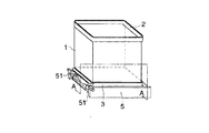
図1は本発明に係るトナー補給容器の斜視図で、その開口部がフィルム状シール材によりシールされている場合を示し、図2はトナー補給のための開口部の断面図(図1のAA断面図)を示す。
【0013】
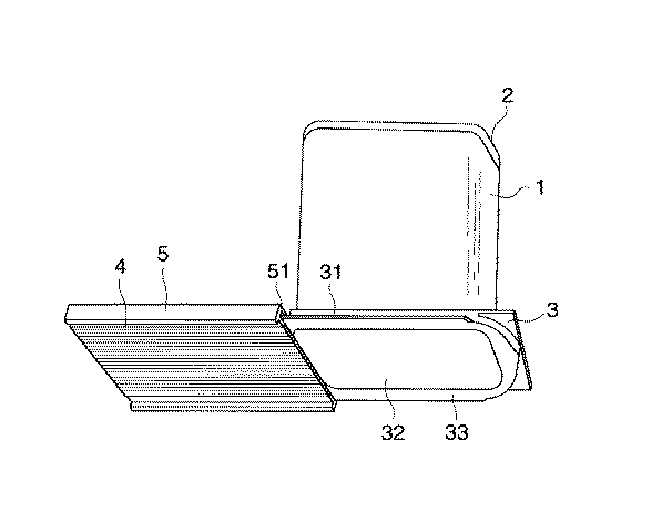
図中1は容器本体で、少なくとも一端が開放された筒状であり、例えば、ポリエチレン、ポリプロピレン、ポリエステル、ポリスチレン等の樹脂で構成されている。2は固定蓋で、金属、プラスチック、紙等を用いることができ、本体と同系樹脂を用いることが好ましい。ここで固定蓋2は容器本体1と共にプラスチック成形物として一体的に成形されてもよい。
【0014】
3は口金部で、容器本体1の開放端に取り付けられ、例えば金属、プラスチック等から作られ、本体と同系樹脂を用いることが好ましい。なお容器本体1を口金部3と共に一体的に成形するようにしてもよい。この口金部3には後述するスライド蓋5のスライド部と係合する突出部31(図3)を、スライド方向に対し左右に有している。
【0015】
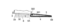
4は口金部3の開口部32をシールするフィルム状シール材であって、開口部32の周面でかつ口金部3の下端面33に剥離可能に、例えば接着剤により接着されるか、ヒートシールにより接着されるか又は加圧により接着される。このフィルム状シール材4の先端は開口部32の一端付近にあたる先端固定部321に接着固定され、下端面33に剥離可能に接着されたのち、延長部は開口部32の他端付近のシール端から折り返され、スライド蓋5の外側を通って口金部3の先端固定部321の近傍で後端固定部322に接着固定される。フィルム状シール材4の材料としてはポリエステルフィルム、ポリエチレンとポリエステルとをラミネートしたもの、ポリプロピレンとポリエステルをラミネートしたもの、アルミ箔にポリエチレン又はポリプロピレンをラミネートしたもの等可撓性でかつ破断等に対して強度のあるものが求められる。
【0016】
スライド蓋5はフィルム状シール材4を牽引し、シール剥離する牽引部材でもある。この実施態様例においては、5は保存時或いは輸送時においてシール用のフィルム状シール材4の保護と、開封用とを兼ねたスライド蓋で、金属、プラスチック等が使用される。このスライド蓋5には、口金部3の突出部31と係合したスライド溝51が設けられている。図2の断面図から明らかなように、容器本体1内のトナーは、保存時或いは輸送時にあっては、フィルム状シール材4及びスライド蓋5の双方により支えられている。
【0017】
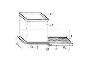
図3はスライド蓋5を開き、フィルム状シール材4を剥離した状態におけるトナー容器の斜視図で、図4はこの状態における断面(図3のBB断面図)を示し、図5は同状態における下方より見た斜視図を示す。本発明に係るシボはスライド蓋5の5A及び/又は5B部につける。
【0018】
スライド蓋5を固定部321(322)の方向(図上で右方向)に引き出すと、スライド蓋5の移動と共にフィルム状シール材4も引っ張られ、開口部32の下端面33の他端側から次第に剥離される。スライド蓋5を右方向に充分引き出した状態では、開口部32は開口状態となって、容器本体1内のトナーTは落下補給される。このとき、スライド蓋5のシール材と強く接する5A及び/又は5Bに適正な値のシボがあると、シール部材4とシール剥離牽引部材としてのスライド蓋5の摩擦係数を小さくし、両者がスムーズに動くようになる。又、開口時に必要な力が小さくなる。
【0019】
トナー補給が終了すると、スライド蓋5を左方にスライドさせる。先に剥離したフィルム状シール材4も元の位置に戻り、図1に示した状態に復帰する。次いで、複写機ホッパーからトナー補給容器が取り外される。
【0020】
なおこの際、フィルム状シール材4におけるトナー容器の底面部に相当する部分は、トナーで汚染されているが、再度トナー容器内に収納されるので、トナー補給装置周辺を汚染することがなく、作業性に優れている。
【0021】
以上説明した例では、フィルム状シール材4の先端は先端固定部321に接着固定されるものとしたが、スライド蓋5のスライド量を一定になるようにストッパーを設ける等により、スライド量を一定に限定したときは、必ずしもフィルム状シール材4の後端は固定する必要はなく、フィルム状シール材4の先端を固定するだけで充分で、この場合は、スライド蓋5の5A部にシボを設ければよく、何れも本発明に含まれる。
【0022】
尚、樹脂を用いて本体を作製する際に、成形方法には2種ある。一つは射出成形方法であり、一方は中空成形方法である。これらの方法に使用される樹脂としてポリプロピレンやポリエチレン等が使用されるが、いずれの方法においても全ての材料が使用されるものでは無く、特にトナー補給容器として使用される場合には、輸送時の衝撃や使用時の衝撃による破損を防止するために、ある範囲のものを使用することがよい。
【0023】
射出成形方法では、金型の隙間に樹脂を流し込む方法であることから、適度な流れ特性が必要である。このため、メルトインデックスが1〜30g/10minであるポリプロピレン及び/又は密度が0.94〜0.97g/cm3のポリエチレンが好ましく使用される。メルトインデックスがこの範囲よりも小さい場合には流れ特性が不良となり、ムラに充填され、結果として容器の外壁が不均一となり強度が不足する問題を発生し、メルトインデックスが大きい場合には流れやすいことから、均一性は高くなるものの、熱安定性が低下し、保存特性が低下してしまう。
【0024】
また、中空成形方法は樹脂を金型中に流出させ、金型をはさみこんだ状態で樹脂中に圧縮空気を吹き込み、金型に密着するようにふくらませ、冷却し固化させ成形する方法である。この方法では、メルトインデックスが0.1〜4g/10minであるポリプロピレン及び/又は密度が0.94〜0.97g/cm3のポリエチレンであることが良好な結果を与える。メルトインデックスが小さい場合には、溶融した状態の樹脂が流れにくいことから、圧縮空気による膨らまし工程段階で均一に膨らませることができず、結果として容器の外壁が不均一となり、容器の衝撃安定性が低下する。また、メルトインデックスが大きい場合には、流れやすいことから、流出状態が不安定となり、特に下端に樹脂が溜まりやすくなることから、容器外壁の上部と下部とで厚みが変化し、結果として衝撃安定性が低下する問題を発生する。
【0025】
なお、衝撃が加わった場合に破損しないためには、特定のアイゾット衝撃値が必要である。具体的には、アイゾット衝撃値が0.1〜30であることがよい。このアイゾット衝撃値が小さい場合には衝撃により容易に破損してしまう。また、アイゾット衝撃値はある範囲以上であれば実用上の衝撃に耐え得るため、この範囲内であればよい。
【0026】
前記したごとく、本発明で望ましく使用されるのはいわゆる高密度ポリエチレンで密度が0.94〜0.97g/cm3のものである。密度の測定方法はJIS K 7112に基づいて測定されるものである。特に、ピクノメーターを用いた測定方法が簡便な方法である。具体的には、洗浄し乾燥したピクノメーターを用意し、その重量を精密に測定する。これをb(g)とする。ついで、23±0.1℃の温度でその標線まで正確に浸せき液を満たし、その重量を精密に測定し、これをe(g)とする。ついで、ピクノメーターを空にし、乾燥した後に試料を1〜5g程度いれ、再度試料をいれた状態でピクノメーターの重量を測定し、乾燥したピクノメーターの重量を差し引いて試料重量を求める。これをa(g)とする。ついで、試料を入れたピクノメーターに浸せき液を加え、試料が覆われた状態で一旦真空デシケーターへ入れ、減圧することで浸せき液中の空気を除く。さらに浸せき液中の空気を除去したピクノメーターへ浸せき液を23±0.1℃の状態で標線まで加え、その重量を測定する。これをc(g)とする。この結果から下記算出式に従って密度を求める。
【0027】
密度(g/cm3)={(a)/((e−b)−(c−e))}×ρ
なお、ここでρは23℃に於ける浸せき液の比重である。
【0028】
また、ポリプロピレンの物性については、ポリプロピレンは密度が0.90〜0.91g/cm3のものが好ましい。
【0029】
アイゾット衝撃値の定義と測定方法については、JIS K 7110に記載の方法、メルトインデックスの定義と測定方法についてはJIS K 7210の方法で、ポリプロピレンは230℃/2.16kg、ポリエチレンは190℃/2.16kgの条件で測定したものである。
【0030】
なお、本発明では、トナー補給容器本体を構成する部分の外壁厚みは特に限定されるものではないが、耐久性を維持する観点から1.0mm以上必要である。また、衝撃が加わった場合に外壁の厚みが不均一であると脆さがでることから、厚みの振れ幅としては1.0mm以下、好ましくは0.5mm以下であることがよい。この厚みの幅は平均厚みと最小厚みの差を示すものである。なお、平均厚みは屈曲部を除いた部分の厚み10箇所をランダムに測定し、その平均値を示す。さらに、最小厚みとは、この10箇所のうちの最小値を示した箇所の値を示す。
【0031】
充填されるトナーの例
本発明のトナー補給容器に充填されるトナーは結着樹脂と着色剤と必要に応じて使用されるその他の添加剤とを含有した着色粒子に必要により無機微粒子を添加混合したトナーである。その平均粒径は体積平均粒径で通常1〜30μm、好ましくは3〜10μmである。着色粒子を構成する結着樹脂としては特に限定されず、従来公知の種々の樹脂が用いられる。
【0032】
例えば、スチレン系樹脂、アクリル系樹脂、スチレン/アクリル系樹脂、ポリエステル樹脂等が挙げられる。着色剤としては特に限定されず、従来カラートナー用として公知の、カーボンブラック、ニグロシン染料、アニリンブルー、カルコイルブルー、クロムイエロー、ウルトラマリンブルー、デュポンオイルレッド、キノリンイエロー、メチレンブルークロライド、フタロシアニンブルー、マラカイトグリーンオクサレート、ローズベンガル等が挙げられる。
【0033】
例えば黒トナーとしてはカーボンブラック、ニグロシン染料等が使用され、イエロー、マゼンタ、シアントナーに必要な顔料としては、C.I.ピグメントブルー15:3、C.I.ピグメントブルー15、C.I.ピグメントブルー15:6、C.I.ピグメントブルー68、C.I.ピグメントレッド48−3、C.I.ピグメントレッド122、C.I.ピグメントレッド212、C.I.ピグメントレッド57−1、C.I.ピグメントイエロー17、C.I.ピグメントイエロー81、C.I.ピグメントイエロー154等の顔料を好適に使用することができる。
【0034】
その他の添加剤としては例えばサリチル酸誘導体・アゾ系金属錯体等の荷電制御剤、低分子量ポリオレフィン、カルナウバワックス等の定着性改良剤等が挙げられる。
【0035】
【実施例】
以下、実施例を挙げて本発明を詳細に説明するが、本発明の態様はこれに限定されない。尚、「部」とは「重量部」を表す。
【0036】
〈トナー製造例〉
スチレン−アクリル樹脂100部に着色剤としてカーボンブラック8部とさらに低分子量ポリプロピレン6部を加え、乾式混合した後に溶融混練、粉砕分球した後に、外添剤として疎水性シリカ0.7部加えて体積平均粒径が8.4μmのトナーを得た。
【0037】
〈トナー補給容器の構成〉
トナー補給容器は図1〜5に示す構成を有し、構成する樹脂としてはポリプロピレン(PP)とポリエチレン(PE)を用いた。
【0038】
最も端的には図4でスライド蓋5(シール剥離牽引部材)の端部5A、5Bに下記のシボ加工を施したトナー補給容器を作った。
【0039】
【表1】
【表2】
〈評価〉
上記各容器に前述のトナーを入れ、シールした後に低温低湿(5℃、10%RH)環境にて剥離性を評価した。評価にてはシール部が剥離するために必要な力と、剥離時のシール部の破断の有無を評価した。
【0042】
結果を下記表3に示す。
【0043】
【表3】
本発明容器1〜4にては、条件的にシール面破断を起こしやすい低温低湿環境下においても、問題なく剥離できるのに対し、比較用の容器1,2ではシボ加工が適正でなく破断を起こすことがわかる。
【0045】
【発明の効果】
本発明により、シール材を剥離する際に大きな力を必要とせず、簡単に剥離することができ、シール材を破損することが無く、容易にトナーを補給することができるトナー補給容器を提供することができる。
【図面の簡単な説明】
【図1】本発明のトナー補給容器の全体斜視図。
【図2】本発明のトナー補給容器の開口部の断面図。
【図3】本発明のトナー補給容器の全体斜視図。
【図4】本発明のトナー補給容器の開口部の断面図。
【図5】本発明のトナー補給容器の全体斜視図。
【符号の説明】
1 容器本体
2 固定蓋
3 口金部
4 フィルム状シール材
5 スライド蓋(シール剥離牽引部材)
32 開口部[0001]
BACKGROUND OF THE INVENTION
The present invention relates to a toner container used for replenishing toner for developing an electrostatic charge image used in a copying machine, a printer or the like.
[0002]
[Prior art]
Conventionally, in electrostatic charge image development widely used in copying machines, printers, etc., toner development is mostly performed. In this method, it is necessary to replenish the toner consumed as the development progresses so as to be simple and free from toner scattering, and toner replenishing containers are being actively developed. For example, there is one described in JP-A-1-280781 as one of representative examples.
[0003]
On the other hand, toner replenishing containers are often made of laminated paper and various plastics. Recently, attempts have been made to collect and reuse these containers in order to reduce industrial waste. However, it is difficult to recycle the laminated paper. Furthermore, when a plastic material is used, if the material composition is different, it is difficult to separate, and it is difficult to collect and reuse. For this reason, it is expected that the material constituting the container is made of the same material as possible, and is made of a plastic resin that is relatively easy to recover and reuse.
[0004]
On the other hand, in this configuration, a seal peeling pulling member is necessary to peel off the sealing material. The sealing material and the seal peeling pulling member are configured to slide. When this structure is used, a force is required for peeling, and if this force becomes too large, there is a problem that the seal surface is damaged.
[0005]
[Problems to be solved by the invention]
An object of the present invention is to solve the above-described problem. Specifically, when the sealing material is peeled off, a large force is not required, and the sealing material can be easily peeled off and the sealing material can be damaged. It is an object of the present invention to provide a toner replenishing container that can easily replenish toner.
[0006]
[Means for Solving the Problems]
The object of the present invention is achieved by adopting the following configuration.
[0007]
(1) a container body having an opening for discharging the toner, and the film-like sealing material which seals the opening, is arranged together with the film-like sealing member, slidably body along the opening In a toner replenishing container having a thin slide lid (seal peeling pulling member) provided on the container, one end of a long sealing material is fixed to the container body and can be peeled off at the lower end surface of the opening. After being bonded, the other end of the sealing material is folded back at the end of the slide lid, passes substantially around the outside of the slide lid, and is further folded back and fixed to the container body. toner supply container, wherein the end portion of the sliding lid is obtained by processing 10 th to 100 th grain which parts are in contact.
[0008]
That is, when the sealing material is peeled off and the end portion to which the force is applied is formed of a smooth surface, the sealing material is in close contact with the sealing material, and a large amount of force is required at that portion. By reducing this force, it was found that the sealing material itself was not damaged and could be easily peeled off with a small force, and the present invention was completed.
[0009]
According to this configuration, the invention can be completed by performing the embossing on the end portion to which the force is applied, and particularly by setting the degree of the processing within a specific range.
[0010]
No. 10 to No. 100 machining is preferable as the texture processing. If it exceeds 100, the effect is small because it is too fine, and if it is less than 10, since the roughness is large, the seal peel strength increases and the effect of the present invention cannot be exhibited.
[0011]
Example of the structure of the toner supply container There are no particular requirements regarding the structure of the toner supply container itself. Here, it demonstrates as a typical example.
[0012]
FIG. 1 is a perspective view of a toner replenishing container according to the present invention, showing the case where the opening is sealed with a film-like sealing material, and FIG. 2 is a cross-sectional view of the opening for toner replenishment (AA in FIG. 1). Sectional view).
[0013]
In the figure,
[0014]
[0015]
4 is a film-like sealing material that seals the
[0016]
The
[0017]
3 is a perspective view of the toner container in a state where the
[0018]
When the
[0019]
When the toner supply is completed, the
[0020]
At this time, the portion corresponding to the bottom surface portion of the toner container in the film-like sealing material 4 is contaminated with the toner, but since it is housed in the toner container again, the vicinity of the toner replenishing device is not contaminated. Excellent workability.
[0021]
In the example described above, the tip of the film-like sealing material 4 is bonded and fixed to the
[0022]
There are two types of molding methods for producing the main body using a resin. One is an injection molding method and the other is a hollow molding method. Polypropylene, polyethylene, and the like are used as resins used in these methods, but not all materials are used in any of these methods, especially when used as a toner supply container. In order to prevent damage due to impact or impact during use, it is better to use a certain range.
[0023]
In the injection molding method, since resin is poured into the gaps of the mold, appropriate flow characteristics are required. For this reason, polypropylene having a melt index of 1 to 30 g / 10 min and / or polyethylene having a density of 0.94 to 0.97 g / cm 3 is preferably used. If the melt index is smaller than this range, the flow characteristics will be poor and will be unevenly filled, resulting in a problem that the outer wall of the container is uneven and the strength is insufficient, and it is easy to flow when the melt index is large Therefore, although the uniformity is increased, the thermal stability is lowered and the storage characteristics are lowered.
[0024]
The hollow molding method is a method in which resin is flown into a mold, compressed air is blown into the resin with the mold sandwiched, and the resin is inflated so as to be in close contact with the mold, cooled and solidified. In this method, a polypropylene having a melt index of 0.1 to 4 g / 10 min and / or a polyethylene having a density of 0.94 to 0.97 g / cm 3 gives good results. When the melt index is small, the molten resin is difficult to flow, so it cannot be uniformly inflated with compressed air, resulting in non-uniform outer wall of the container and impact stability of the container Decreases. In addition, when the melt index is large, it is easy to flow, and the outflow state becomes unstable. Especially, the resin tends to accumulate at the lower end, so the thickness changes at the upper and lower parts of the outer wall of the container, resulting in stable impact. This causes a problem that the performance decreases.
[0025]
It should be noted that a specific Izod impact value is required in order to prevent damage when an impact is applied. Specifically, the Izod impact value is preferably 0.1 to 30. When this Izod impact value is small, it is easily damaged by impact. Further, if the Izod impact value is within a certain range, the Izod impact value can withstand a practical impact, and therefore it should be within this range.
[0026]
As described above, what is desirably used in the present invention is a so-called high density polyethylene having a density of 0.94 to 0.97 g / cm 3 . The measuring method of density is measured based on JIS K7112. In particular, a measurement method using a pycnometer is a simple method. Specifically, a washed and dried pycnometer is prepared and its weight is accurately measured. This is b (g). Next, the immersion liquid is filled up to the marked line accurately at a temperature of 23 ± 0.1 ° C., and its weight is measured accurately, and this is defined as e (g). Next, the pycnometer is emptied, and after drying, about 1 to 5 g of the sample is added. The weight of the pycnometer is measured with the sample added again, and the weight of the dried pycnometer is subtracted to obtain the sample weight. This is a (g). Next, the immersion liquid is added to the pycnometer containing the sample, and the sample is covered, and once put into a vacuum desiccator, the air in the immersion liquid is removed by reducing the pressure. Further, add the immersion liquid up to the marked line at 23 ± 0.1 ° C. to the pycnometer from which the air in the immersion liquid has been removed, and measure the weight. Let this be c (g). From this result, the density is determined according to the following calculation formula.
[0027]
Density (g / cm 3 ) = {(a) / ((eb) − (ce))} × ρ
Here, ρ is the specific gravity of the immersion liquid at 23 ° C.
[0028]
As for the physical properties of polypropylene, the polypropylene preferably has a density of 0.90 to 0.91 g / cm 3 .
[0029]
For the definition and measurement method of the Izod impact value, the method described in JIS K 7110, and for the definition and measurement method of the melt index, the method of JIS K 7210, 230 ° C / 2.16kg for polypropylene and 190 ° C / 2 for polyethylene. Measured under the condition of 16 kg.
[0030]
In the present invention, the thickness of the outer wall of the portion constituting the toner supply container main body is not particularly limited, but is required to be 1.0 mm or more from the viewpoint of maintaining durability. In addition, if the thickness of the outer wall is not uniform when an impact is applied, the brittleness appears. Therefore, the thickness fluctuation width is 1.0 mm or less, preferably 0.5 mm or less. The width of this thickness indicates the difference between the average thickness and the minimum thickness. In addition, average thickness measures the thickness 10 places of the part except a bending part at random, and shows the average value. Furthermore, the minimum thickness indicates a value of a portion showing the minimum value among the ten locations.
[0031]
Example of toner to be filled The toner to be filled in the toner replenishing container of the present invention is a mixture of colored particles containing a binder resin, a colorant, and other additives used as necessary, and if necessary inorganic particles are added and mixed. Toner. The average particle diameter is a volume average particle diameter of usually 1 to 30 μm, preferably 3 to 10 μm. The binder resin constituting the colored particles is not particularly limited, and various conventionally known resins are used.
[0032]
For example, a styrene resin, an acrylic resin, a styrene / acrylic resin, a polyester resin, and the like can be given. The colorant is not particularly limited, and is conventionally known for color toners, such as carbon black, nigrosine dye, aniline blue, calcoil blue, chrome yellow, ultramarine blue, DuPont oil red, quinoline yellow, methylene blue chloride, phthalocyanine blue, Examples include malachite green oxalate and rose bengal.
[0033]
For example, carbon black, nigrosine dye or the like is used as the black toner, and pigments necessary for yellow, magenta and cyan toners are C.I. I. Pigment blue 15: 3, C.I. I. Pigment blue 15, C.I. I. Pigment blue 15: 6, C.I. I. Pigment blue 68, C.I. I. Pigment red 48-3, C.I. I. Pigment red 122, C.I. I. Pigment red 212, C.I. I. Pigment red 57-1, C.I. I. Pigment yellow 17, C.I. I. Pigment yellow 81, C.I. I. Pigment yellow 154 or the like can be preferably used.
[0034]
Examples of other additives include charge control agents such as salicylic acid derivatives and azo metal complexes, and fixability improvers such as low molecular weight polyolefins and carnauba wax.
[0035]
【Example】
EXAMPLES Hereinafter, although an Example is given and this invention is demonstrated in detail, the aspect of this invention is not limited to this. “Parts” represents “parts by weight”.
[0036]
<Example of toner production>
Add 100 parts of carbon black as a colorant and 6 parts of low molecular weight polypropylene to 100 parts of styrene-acrylic resin, dry mix, melt knead, pulverize and smash, then add 0.7 part of hydrophobic silica as an external additive. A toner having a volume average particle diameter of 8.4 μm was obtained.
[0037]
<Configuration of toner supply container>
The toner supply container has the configuration shown in FIGS. 1 to 5, and polypropylene (PP) and polyethylene (PE) were used as the constituent resin.
[0038]
Most simply, in FIG. 4, a toner replenishing container in which the following embossing is applied to the
[0039]
[Table 1]
[Table 2]
<Evaluation>
The above toner was put in each of the above containers and sealed, and then the peelability was evaluated in a low temperature and low humidity (5 ° C., 10% RH) environment. In the evaluation, the force necessary for the seal part to peel and the presence or absence of breakage of the seal part at the time of peeling were evaluated.
[0042]
The results are shown in Table 3 below.
[0043]
[Table 3]
The
[0045]
【The invention's effect】
According to the present invention, there is provided a toner replenishing container that does not require a large force when peeling off the sealing material, can be easily peeled off, can be easily replenished without damaging the sealing material. be able to.
[Brief description of the drawings]
FIG. 1 is an overall perspective view of a toner supply container of the present invention.
FIG. 2 is a cross-sectional view of an opening of a toner supply container according to the present invention.
FIG. 3 is an overall perspective view of a toner supply container according to the present invention.
FIG. 4 is a cross-sectional view of an opening of a toner supply container according to the present invention.
FIG. 5 is an overall perspective view of the toner supply container of the present invention.
[Explanation of symbols]
DESCRIPTION OF
32 opening
Claims (1)
Priority Applications (1)
| Application Number | Priority Date | Filing Date | Title |
|---|---|---|---|
| JP25606496A JP4265700B2 (en) | 1996-09-27 | 1996-09-27 | Toner supply container |
Applications Claiming Priority (1)
| Application Number | Priority Date | Filing Date | Title |
|---|---|---|---|
| JP25606496A JP4265700B2 (en) | 1996-09-27 | 1996-09-27 | Toner supply container |
Publications (2)
| Publication Number | Publication Date |
|---|---|
| JPH10104922A JPH10104922A (en) | 1998-04-24 |
| JP4265700B2 true JP4265700B2 (en) | 2009-05-20 |
Family
ID=17287406
Family Applications (1)
| Application Number | Title | Priority Date | Filing Date |
|---|---|---|---|
| JP25606496A Expired - Fee Related JP4265700B2 (en) | 1996-09-27 | 1996-09-27 | Toner supply container |
Country Status (1)
| Country | Link |
|---|---|
| JP (1) | JP4265700B2 (en) |
-
1996
- 1996-09-27 JP JP25606496A patent/JP4265700B2/en not_active Expired - Fee Related
Also Published As
| Publication number | Publication date |
|---|---|
| JPH10104922A (en) | 1998-04-24 |
Similar Documents
| Publication | Publication Date | Title |
|---|---|---|
| KR940001084B1 (en) | Developer and process cartridge having it | |
| US4895104A (en) | Developer reservoir | |
| US7634217B2 (en) | Electrophotographic image forming method using a double walled toner cartridge | |
| US6999705B2 (en) | Powder container, powder contained product, powder container manufacturing method, powder contained product reusing method, toner container and toner contained product | |
| US9519237B2 (en) | Electrostatic latent image developing toner, method for manufacturing electrostatic latent image developing toner, and method for fixing electrostatic latent image developing toner | |
| JP4265700B2 (en) | Toner supply container | |
| JP3941313B2 (en) | Setting method of upper limit of toner filling amount | |
| US6295426B1 (en) | Toner cartridge | |
| JPH10104924A (en) | Toner supplying vessel | |
| JPH11321941A (en) | Container for particulate matter | |
| US6033821A (en) | Electrophotographic transfer sheet and method for forming color image | |
| JP3571906B2 (en) | Developer supply container and image forming apparatus | |
| JPH10142911A (en) | Toner replenishing container | |
| JP3270550B2 (en) | Developer container | |
| JP3874450B2 (en) | Toner supply container, electrostatic image developing method, and developing device | |
| JP4370755B2 (en) | Toner storage container, toner storage product, and toner storage container manufacturing method | |
| JPH09325585A (en) | Toner replenishing container and toner replenishing method | |
| JP4562063B2 (en) | Powder container, powder container product, powder filling method, powder supply method, electrostatic charge image developing toner container and toner container product | |
| US5978624A (en) | Slide cover breathable seal for a marking particle receptacle | |
| US5970284A (en) | Slide cover for marking particle receptacle | |
| JP2003312756A (en) | Powder housing container and powder-housed product, manufacturing method for the powder housing container, recycling method for the powder-housed product, toner housing container, and toner-housed product | |
| JPH09288416A (en) | Toner replenishment container | |
| JP3846746B2 (en) | Toner supply container | |
| JP3376358B2 (en) | Developer supply container | |
| JPH09319195A (en) | Toner replenishing container |
Legal Events
| Date | Code | Title | Description |
|---|---|---|---|
| A02 | Decision of refusal |
Free format text: JAPANESE INTERMEDIATE CODE: A02 Effective date: 20040706 |
|
| A521 | Written amendment |
Free format text: JAPANESE INTERMEDIATE CODE: A523 Effective date: 20040902 |
|
| A521 | Written amendment |
Free format text: JAPANESE INTERMEDIATE CODE: A523 Effective date: 20040929 |
|
| A911 | Transfer of reconsideration by examiner before appeal (zenchi) |
Free format text: JAPANESE INTERMEDIATE CODE: A911 Effective date: 20041108 |
|
| A912 | Removal of reconsideration by examiner before appeal (zenchi) |
Free format text: JAPANESE INTERMEDIATE CODE: A912 Effective date: 20050204 |
|
| A521 | Written amendment |
Free format text: JAPANESE INTERMEDIATE CODE: A523 Effective date: 20061013 |
|
| A01 | Written decision to grant a patent or to grant a registration (utility model) |
Free format text: JAPANESE INTERMEDIATE CODE: A01 |
|
| A61 | First payment of annual fees (during grant procedure) |
Free format text: JAPANESE INTERMEDIATE CODE: A61 Effective date: 20090210 |
|
| R150 | Certificate of patent or registration of utility model |
Free format text: JAPANESE INTERMEDIATE CODE: R150 |
|
| FPAY | Renewal fee payment (event date is renewal date of database) |
Free format text: PAYMENT UNTIL: 20120227 Year of fee payment: 3 |
|
| FPAY | Renewal fee payment (event date is renewal date of database) |
Free format text: PAYMENT UNTIL: 20120227 Year of fee payment: 3 |
|
| FPAY | Renewal fee payment (event date is renewal date of database) |
Free format text: PAYMENT UNTIL: 20130227 Year of fee payment: 4 |
|
| FPAY | Renewal fee payment (event date is renewal date of database) |
Free format text: PAYMENT UNTIL: 20130227 Year of fee payment: 4 |
|
| FPAY | Renewal fee payment (event date is renewal date of database) |
Free format text: PAYMENT UNTIL: 20140227 Year of fee payment: 5 |
|
| S531 | Written request for registration of change of domicile |
Free format text: JAPANESE INTERMEDIATE CODE: R313531 |
|
| S533 | Written request for registration of change of name |
Free format text: JAPANESE INTERMEDIATE CODE: R313533 |
|
| R350 | Written notification of registration of transfer |
Free format text: JAPANESE INTERMEDIATE CODE: R350 |
|
| LAPS | Cancellation because of no payment of annual fees |