JP4265021B2 - Recording apparatus and laser power setting method - Google Patents
Recording apparatus and laser power setting method Download PDFInfo
- Publication number
- JP4265021B2 JP4265021B2 JP04464899A JP4464899A JP4265021B2 JP 4265021 B2 JP4265021 B2 JP 4265021B2 JP 04464899 A JP04464899 A JP 04464899A JP 4464899 A JP4464899 A JP 4464899A JP 4265021 B2 JP4265021 B2 JP 4265021B2
- Authority
- JP
- Japan
- Prior art keywords
- recording
- power
- opc
- erasing
- optimum
- Prior art date
- Legal status (The legal status is an assumption and is not a legal conclusion. Google has not performed a legal analysis and makes no representation as to the accuracy of the status listed.)
- Expired - Fee Related
Links
Images


Description
【0001】
【発明の属する技術分野】
本発明は、光ディスク等の記録媒体に対する記録装置、及び記録装置におけるレーザパワー設定方法に関するものである。
【0002】
【従来の技術】
ディスク等の記録媒体に対してレーザ光を照射してデータの記録を行う機器が各種実現されている。
例えば光学ディスク記録媒体としてCD(コンパクトディスク)方式のディスクや、マルチメディア用途に好適なDVD(Digital Versatile Disc/Digital Video Disc)と呼ばれるディスクなどが開発されており、これらの光ディスクに対応する記録装置では、ディスク上のトラックに対して記録データによって変調されたレーザ光を照射し、例えば相変化記録方式でデータの記録を行う。
【0003】
【発明が解決しようとする課題】
ところで、このようにレーザ光によりデータ記録を行う場合には、レーザ光のパワー、具体的には、記録パワーや消去パワーが適切な値に設定されていなければならない。
このために、通常、記録装置では、OPC(オプティマムパワーコントロール)と呼ばれる最適レーザパワーの判別動作が行われる。
【0004】
このOPC動作は、ディスク上に用意された試し書き領域(テスト領域)に対してレーザパワーを変化させながらレーザ照射を行って試し書きを行い、その試し書き部分の再生情報の品質(例えばジッタレベル等)を監視することで、最適なレーザパワーを判別する動作となる。
このようなOPC動作により、記録時に最適なレーザパワーによる記録動作が実現できる。
このOPC動作方式としては従来、以下の▲1▼〜▲3▼のような動作例があるが、それぞれ問題がある。
【0005】
▲1▼ OPC動作において、記録パワーのみを変化させて試し書きを行い、最適な記録パワーを判別する。
この動作方式の場合、記録パワーの最適値を見つけるのみで、最適な消去パワーについては判別していない。従って記録パワーと消去パワーがそれぞれ影響を与える記録データ品質については、十分に保証されないものとなる。
【0006】
▲2▼ 記録パワー、消去パワー、冷却パワーの3値をそれぞれ各種の組み合わせで変化させて試し書きを行い、最適な組み合わせを判別する。
この場合は、3つのパワーの組み合わせであることと、パワーレベルのステップ数が多いことにより、組み合わせの数は非常に多くなる。従って最適な組み合わせを精度良く判別しようとすれば、OPC動作にかなりの時間がかかってしまうことになる。また、時間を掛けないようにすれば(つまり組み合わせ数を絞れば)最適なパワーの判別精度は落ちてしまうことになる。
【0007】
▲3▼ まず最適な消去パワーを検出し、その後にDC消去を行い、その後上記▲1▼又は▲2▼の方式で最適記録パワーを見つける。
消去パワー検出後に方式▲1▼を行うようにした場合は、方式▲1▼の倍の時間がかかることになる。
また消去パワー検出後に方式▲2▼を行うようにした場合は、もともと時間的に長くなる方式▲2▼を利用することで(消去パワーが固定されるため、その分組み合わせ数を減らすことはできるが)かなりの時間がかかることになる。
【0008】
これらのように、精度良くかつ効率的に記録パワー、消去パワーを判別できないという問題があった。
【0009】
【課題を解決するための手段】
本発明はこれらの問題点に鑑みて、OPC動作の精度及び動作効率を向上させることを目的とする。
【0011】
このために、本発明の記録装置は、装填された記録媒体の試し書き領域に対して、レーザパワーを変化させながら記録ヘッド手段による記録動作及びその再生動作を実行させていくことで、ジッター又はエラーレートが最適となる記録パワーと消去パワーの組み合わせの近似式を求めるとともに、求められた近似式を利用してレーザパワーを変化させながら記録ヘッド手段による記録動作及びその再生動作を実行させて、アシンメトリ値が最適となる記録パワーと消去パワーを求め、これを最適な記録パワーと消去パワーと判別するレーザパワー判別手段を備えるようにする。
【0012】
即ち、記録パワーと消去パワーの比又は最適組み合わせの近似式を求め、これらを利用してパワー変動範囲を設定して試し書きを行うことで、効率よく、かつ精度の良いOPC動作を実現する。
【0014】
また本発明のレーザパワー設定方法としては、同じくジッター又はエラーレートが最適となる記録パワーと消去パワーの比を検出した後、消去パワーを所定値に固定し、記録パワーを変化させながら記録を行った後に再生し、アシンメトリ値が最適となる記録パワーを検出する。次に検出された記録パワーと比から消去パワーの好適範囲を判断し、検出された記録パワーを固定したうえで消去パワーを好適範囲内で変化させながら記録を行った後に再生し、アシンメトリ値が最適となる消去パワーを検出する。そして検出された記録パワーと消去パワーを、記録動作に用いるレーザパワーとして設定する。
【0015】
また本発明のレーザパワー設定方法としては、記録パワーを固定し、消去パワーを変化させながら記録を行った後に再生し、ジッター又はエラーレートが最適となる記録パワーと消去パワーの組み合わせを検出する動作を、記録パワーの固定値を変化させて複数回実行する。次に、検出された複数個の記録パワーと消去パワーの組み合わせから、記録パワーと消去パワーの組み合わせの近似式を求める。次に、算出された近似式に基づく記録パワーと消去パワーの組み合わせを維持したうえで、記録パワーと消去パワーを変化させながら記録を行った後に再生し、アシンメトリ値が最適となる記録パワー、消去パワーの組み合わせを検出する。そして検出された記録パワーと消去パワーの組み合わせを、記録動作に用いるレーザパワーとして設定する。
【0016】
また本発明のレーザパワー設定方法としては、同じくジッター又はエラーレートが最適となる記録パワーと消去パワーの組み合わせの近似式を算出した後、消去パワーを所定値に固定し、記録パワーを変化させながら記録を行った後に再生し、アシンメトリ値が最適となる記録パワーを検出する。次に、検出された記録パワーと近似式から消去パワーの好適範囲を判断し、検出された記録パワーを固定したうえで消去パワーを好適範囲内で変化させながら記録を行った後に再生し、アシンメトリ値が最適となる消去パワーを検出する。そして検出された記録パワーと消去パワーを、記録動作に用いるレーザパワーとして設定する。
【0017】
【発明の実施の形態】
以下、本発明の実施の形態として、記録可能な光ディスクに対応する記録再生装置及びその記録再生装置で実行される記録方法、レーザパワー設定方法について説明していく。この例の記録再生装置に装填される光ディスクは、例えば、CD−RなどのCD方式のディスクや、DVD(DIGITAL VERSATILE DISC/DIGITAL VIDEO DISC)と呼ばれるディスクなどが考えられる。もちろん他の種類の光ディスクに対応する記録装置でも本発明は適用できるものである。
説明は次の順序で行う。
1.光ディスクのフォーマット
2.記録再生装置の構成
3.レーザパワー設定手順の概略
4.動作方式
4−1 DOW特性安定化処理
4−2 ディスク装填時の処理例(A)〜(C)
4−3 OPC処理例(I)〜(III)
4−4 OPC使用エリア選択処理例(イ)〜(ハ)
4−5 ディフェクトキャンセル方式
4−6 OPC動作例(1)〜(4)
4−7 OPC動作時の記録パターン
【0018】
1.光ディスクのフォーマット
本例で記録媒体となる光ディスクは、相変化方式でデータの記録を行う光ディスクであり、その物理的なフォーマットは図1に示されるようになる。
【0019】
ディスクサイズとしては、直径が120mmとされる。また、ディスク厚(サブストレート)0.6mm板の2枚張り合わせディスクとされ、全体としてディスク厚は1.2mmとなる。またディスククランピングはメカニカル方式が採用される。即ちこれらの点では外形的に見ればCD(Compact Disc)、DVD−ROM(Digital Versatile Disc-ROM/Digital Video Disc-ROM)等と同様となる。
また記録再生装置に装填される際などに用いることのできる、当該ディスクを収納保持するケースがオプションとして用意される。
【0020】
ディスク上には予めグルーブ(溝)によるトラックが形成され、このグルーブがウォブリング(蛇行)されることにより物理アドレスが表現される。つまりグルーブがアドレスを変調した信号によってウォブリングされることで、グルーブからの再生情報を復調することで絶対アドレスが抽出できるようにされている。
またディスクはCAV(角速度一定)方式で回転駆動されるものとされ、これに応じてグルーブに含まれる絶対アドレスはCAVデータとなる。
グルーブの深さは記録再生のためのレーザ波長λ/8、グルーブ幅は0.48μm中心、ウォブリング振幅は12.5nm中心とされている。
なおレーザ波長λ=650nm(−5/+15nm)、記録再生装置の光学ヘッドの開口率NA=0.6とされる。
【0021】
この光ディスクでは、グルーブ記録方式が採用され(ランドは記録に用いられない(但し用いられるようにしてもよい))、トラック幅方向にグルーブのセンターから隣接するグルーブのセンターまでがトラックピッチとなる。トラックピッチは0.80μmとされる。
またデータ記録は線密度一定(CLD:Constant Linear Density )とされて記録される。線密度は0.35μm/bit とされる。
但し線密度範囲として或る幅が設定され、実際には非常に多数のゾーニング設定が行われることで、ディスク全体として線密度一定に近い状態とされる。これはゾーンCLD(Zoned Constant Linear Density )と呼ばれる。そしてこのディスクでは、片面(一方の記録層)で3.0Gバイト/の記録容量を実現することができる。
【0022】
また記録データの変調方式としてはいわゆるDVDと同様に8−16変調が採用され、相変化記録媒体へのマークエッジ記録が行われる。
【0023】
図2にディスクの内周側(リードイン)から外周側(リードアウト)までのエリア構造を示す。この構造図の右側には絶対アドレス(セクターアドレス)の値を16進表記で付記している。また各エリアの名称を「***ゾーン」としているが、この各エリアに( )内で示した数値は、そのゾーンのセクター数を表している。
【0024】
内周側(半径位置22.6mm〜24.0mm)の斜線を付した部分はエンボスピットが記録されたエリアとされる。
一方、斜線を付していない部分(半径位置24.0mmから最外周までの領域)は、グルーブによるトラックが形成された記録可能領域(グルーブエリア)となる。
【0025】
エンボスエリアとされる最内周側は、絶対アドレス「02EFFFh」までがイニシャルゾーンとしてオール「00h」のデータが記録されている。
続いて絶対アドレス「2F000h」の位置からが、リファレンスコードが2ECCブロック(以下、単にブロックともいう)分記録された32セクターのリファレンスコードゾーンとなる。なおブロック(ECCブロック)とは、エラー訂正ブロックを構成する単位であり、32Kバイトのデータ毎にエラー訂正コードが付加されて形成される。
続いて、480セクターのバッファゾーンを介して絶対アドレス「2F200h」の位置から3072セクターのコントロールデータゾーンが形成され、コントロールデータが記録される。
これらのコントロールデータ及びリファレンスコードは、原盤製造のためのカッティングの際に記録され、読出専用のピットデータとなる。コントロールデータには、光ディスクの物理的な管理情報などが記録される。
【0026】
続くバッファゾーンがエンボスエリアの最外周側となり、コネクションゾーンから外周側がグルーブエリアとなる。
そしてこのグルーブエリアでは、コネクションゾーンに続いて、512セクターのガードゾーン、1024セクターのインナーディスクテストゾーン、1664セクターのインナードライブテストゾーン、512セクターのガードゾーン、64セクターのDMA1ゾーン(ディフェクトマネジメントエリア)、256セクターのインナーディスクアイデンティフィケーションゾーン、64セクターのDMA2ゾーンが設けられる。
【0027】
このDMA2ゾーンに続いて、ユーザーがデータ記録に用いることができるレコーダブルエリアとしてのデータゾーンが形成される。データゾーンは絶対アドレスでいえば31000h〜198FFFhまでとなる。
【0028】
また、データゾーンの外周側には、64セクターのDMA3ゾーン、256セクターのアウターディスクアイデンティフィケーションゾーン、64セクターのDMA4ゾーン、1024セクターのガードゾーン、2048セクターのアウターディスクテストゾーン、3072セクターのアウタードライブテストゾーン、32768セクターのガードゾーンが設けられる。
【0029】
各ガードゾーンは、ディスクテストゾーンやDMA等に対する書込を行う際にライトクロックの同期をとるためのエリアとして設けられている。
内周側(インナー)及び外周側(アウター)のディスクテストゾーンは、ディスクコンディションのチェックのために設けられている。
内周側(インナー)及び外周側(アウター)のドライブテストゾーンは記録再生ドライブ状況のチェックに用いられる。
特に後述するDOW特性安定化処理や、OPC動作は、このドライブテストゾーンを使用することになる。
内周側(インナー)及び外周側(アウター)のディスクアイデンティフィケーションゾーンは、ディスクの製造者やフォーマットに関しての情報が記録可能に用意されたエリアである。後述するが、例えばこのエリアを利用してドライブテストゾーンの管理テーブルを記録することなどが可能となる。
【0030】
DMA(DMA1〜DMA4)にはレコーダブルエリアの欠陥状況の検出結果及びその交代セクターの情報が記録される。記録再生動作がDMAの内容を参照して行われることで、欠陥領域(例えば傷の存在するセクター)を回避した記録再生を行うことができる。なおDMA1〜DMA4はそれぞれ同一の内容が記録される。
【0031】
2.記録再生装置の構成
図3は本例の記録再生装置の要部のブロック図である。この記録再生装置は、接続されたホストコンピュータ100からの要求に応じてデータの記録再生動作を行うものとされる。
【0032】
ディスク90は上述したフォーマットのDVD方式のディスクや、CD−R,CD−ROM等のCD方式のディスクである。このディスク90は、ターンテーブル7に積載され、記録又は再生動作時においてスピンドルモータ1によって一定線速度(CLV)もしくは一定角速度(CAV)で回転駆動される。
そしてピックアップ1によってディスク90にエンボスピット形態や相変化ピット(マーク)形態などで記録されているデータの読み出しや、相変化ピット(マーク)としてのデータの記録、或いはデータ消去が行なわれることになる。
【0033】
ピックアップ1内には、レーザ光源となるレーザダイオード4や、反射光を検出するためのフォトディテクタ5、レーザ光の出力端となる対物レンズ2、レーザ光を対物レンズ2を介してディスク記録面に照射し、またその反射光をフォトディテクタ5に導く光学系が形成される。
対物レンズ2は二軸機構3によってトラッキング方向及びフォーカス方向に移動可能に保持されている。
またピックアップ1全体はスレッド機構8によりディスク半径方向に移動可能とされている。
【0034】
再生時及び記録時にレーザ光の照射を行うことで得られるディスク90からの反射光情報はフォトディテクタ5によって検出され、受光光量に応じた電気信号とされてRFアンプ9に供給される。
RFアンプ9には、フォトディテクタ5としての複数の受光素子からの出力電流に対応して電流電圧変換回路、マトリクス演算/増幅回路等を備え、マトリクス演算処理により必要な信号を生成する。例えば再生データであるRF信号、サーボ制御のためのフォーカスエラー信号FE、トラッキングエラー信号TEなどを生成する。
RFアンプ9から出力される再生RF信号は2値化回路11へ、フォーカスエラー信号FE、トラッキングエラー信号TEはサーボプロセッサ14へ供給される。
【0035】
ディスク90に対する再生動作時において、RFアンプ9で得られた再生RF信号は2値化回路11で2値化されることでいわゆるEFM信号(8−14変調信号;CD方式のディスク場合)もしくはEFM+信号(8−16変調信号;DVD方式のディスクの場合)とされ、エンコーダ/デコーダ12に供給される。エンコーダ/デコーダ12ではEFM復調,エラー訂正処理等を行ない、また必要に応じてCD−ROMデコード、MPEGデコードなどを行なってディスク90から読み取られた情報の再生を行なう。
【0036】
エンコーダ/デコーダ12でデコードされたデータはキャッシュメモリ20の読出/書込処理を行うバッファマネージャ21の動作によってキャッシュメモリ20に蓄積されていく。いわゆるバッファリング動作が行われる。
再生装置からの再生出力としては、キャッシュメモリ20にバッファリングされたデータが転送出力されることになる。
なお、キャッシュメモリ20からのデータの転送出力はシステムコントローラ10の制御(ファームウエアとしての制御)によって行われる。
【0037】
インターフェース部13は、外部のホストコンピュータと接続され、ホストコンピュータとの間で再生データやリードコマンドの通信を行う。
即ちキャッシュメモリ20に格納された再生データは、インターフェース部13を介してホストコンピュータ100に転送出力される。
またホストコンピュータ100からのリードコマンドその他の信号はインターフェース部13を介してシステムコントローラ10に供給される。
【0038】
サーボプロセッサ14は、RFアンプ9からのフォーカスエラー信号FE、トラッキングエラー信号TEや、デコーダ12もしくはシステムコントローラ10からのスピンドルエラー信号SPE等から、フォーカス、トラッキング、スレッド、スピンドルの各種サーボドライブ信号を生成しサーボ動作を実行させる。
即ちフォーカスエラー信号FE、トラッキングエラー信号TEに応じてフォーカスドライブ信号、トラッキングドライブ信号を生成し、二軸ドライバ16に供給する。二軸ドライバ16はピックアップ1における二軸機構3のフォーカスコイル、トラッキングコイルを駆動することになる。これによってピックアップ1、RFアンプ9、サーボプロセッサ14、二軸ドライバ16、二軸機構3によるトラッキングサーボループ及びフォーカスサーボループが形成される。
【0039】
なお、理想的にはフォーカスエラー信号FEがゼロとなるポイントと、ディスク90から最も効率よく情報再生を行うことができるポイント(つまり再生RF信号の振幅が最大となるポイント)は同一であるはずであるが、実際には、これらのポイントはずれたものとなる。このずれ分をフォーカスバイアスとよび、そのフォーカスバイアス分に相当するバイアス電圧をフォーカスエラー信号FEに加算するようにサーボ系を構成することで、フォーカス状態が、再生RF信号の振幅が最大となるポイントに収束されるように制御している。
トラッキングエラー信号TEについても同様に、トラッキングバイアスが存在する。
【0040】
またサーボプロセッサ14はスピンドルモータドライバ17に対して、スピンドルエラー信号SPEに応じて生成したスピンドルドライブ信号を供給する。スピンドルモータドライバ17はスピンドルドライブ信号に応じて例えば3相駆動信号をスピンドルモータ6に印加し、スピンドルモータ6のCLV回転を実行させる。またサーボプロセッサ14はシステムコントローラ10からのスピンドルキック/ブレーキ制御信号に応じてスピンドルドライブ信号を発生させ、スピンドルモータドライバ17によるスピンドルモータ6の起動または停止などの動作も実行させる。
【0041】
サーボプロセッサ14は、例えばトラッキングエラー信号TEの低域成分として得られるスレッドエラー信号や、システムコントローラ10からのアクセス実行制御などに基づいてスレッドドライブ信号を生成し、スレッドドライバ15に供給する。スレッドドライバ15はスレッドドライブ信号に応じてスレッド機構8を駆動する。スレッド機構8には図示しないが、ピックアップ1を保持するメインシャフト、スレッドモータ、伝達ギア等による機構を有し、スレッドドライバ15がスレッドドライブ信号に応じてスレッドモータ8を駆動することで、ピックアップ1の所要のスライド移動が行なわれる。
【0042】
ピックアップ1におけるレーザダイオード4はレーザドライバ18によってレーザ発光駆動される。
システムコントローラ10はディスク90に対する記録動作、再生動作を実行させる際に、レーザパワーの制御値をオートパワーコントロール回路19にセットし、オートパワーコントロール回路19はセットされたレーザパワーの値に応じてレーザ出力が行われるようにレーザドライバ18を制御する。
【0043】
ディスク90に対する記録動作時には、記録データに応じて変調された信号がレーザドライバ18に印加される。
例えば記録可能タイプのディスク90に対して記録を行う際には、ホストコンピュータからインターフェース部13に供給された記録データは、エンコーダ/デコーダ12によってエラー訂正コードの付加、EFM+変調、NRZI変調などの処理が行われた後、レーザドライバ18に供給される。
そしてレーザドライバ18が記録データに応じてレーザ発光動作をレーザダイオード4に実行させることで、ディスク90に対するデータ記録が実行される。
【0044】
以上のようなサーボ及びデコード、エンコードなどの各種動作はマイクロコンピュータによって形成されたシステムコントローラ10により制御される。
例えば一連の再生動作制御としては、システムコントローラ10はホストコンピュータ100からのリードコマンドに応じて、要求されたデータ区間の読出を行うための動作として、サーボプロセッサ14に指令を出し、リードコマンドにより転送要求されたデータ区間の開始位置をターゲットとするピックアップ1のアクセス動作を実行させる。そしてアクセス終了後、データ読出を実行させ、エンコーダ/デコーダ12、キャッシュメモリ20に必要な処理を実行させ、その再生データ(要求されたデータ)をインターフェース部13からホストコンピュータ100に転送させる制御を行う。
また記録動作制御としては、システムコントローラ10はホストコンピュータ100からのライトコマンドに応じて、供給されたデータの書込を行うための動作として、サーボプロセッサ14に指令を出し、書込開始位置へのピックアップ1のアクセス動作を実行させる。そしてアクセス終了後、キャッシュメモリ20、エンコーダ/デコーダ12、レーザドライバ18等に必要な処理を実行させ、その記録データ(供給されたデータ)をディスク90に記録させる制御を行う。
【0045】
ところで、記録動作に関してレーザダイオード4から出力させるレーザパワー、即ち記録パワー、消去パワーについては、それを最適なパワーとするために、記録動作に先立ってOPC動作が行われる。
【0046】
記録時には、ディスク90の結晶状態にしたトラック上に大きなパワー(記録パワー)を持つレーザ光を照射し、記録面の記録膜を溶融した後に急冷し、アモルファス化させることによって記録マークを形成する。
消去するときは、記録時よりも小さいパワー(消去パワー)のレーザ光を記録マークに照射させて、アモルファス化した部分を再び結晶化させるものとなる。
このため、最適な記録パワー、消去パワーが設定されていないと、適切なオーバーライトが実行できないものとなる。このため、記録動作に先立って最適な記録パワー、消去パワーを設定するOPC動作が必要となる。
【0047】
システムコントローラ10はOPC動作のために、レーザドライバ18及びオートパワーコントロール回路19を制御して、レーザパワーを各種値に変化させながら上述したディスク90のドライブテストゾーンに対して試し書きを実行させ、さらにその試し書き部分を再生させて信号品質を監視する。特に再生信号のジッタ又はエラーレートと、アシンメトリ値を監視する。
このために、RFアンプ9からのRF信号は検出部23に供給され、検出部23からはジッタ又はエラーレートの検出値DJ、及びアシンメトリの検出値DASが出力されるように構成されている。システムコントローラ10はこれらの検出値DJ、DASを取り込むことで、各種レーザパワー状態での信号品質を判断することができ、それによって最適な記録パワー、消去パワーを判別できる。
そして最適な記録パワー、消去パワーを判別したら、それを記録動作時に用いる記録パワー、消去パワーとしてオートパワーコントロール回路19にセットすることで、以降、記録動作時には最適な記録パワー、消去パワーによるレーザ出力が実現されることになる。
【0048】
このようなOPC動作、及びOPC動作の前後の一連の動作(記録のためのレーザパワー設定に関する一連の動作)については後に詳述するが、それらの後述する各種動作は、システムコントローラ10の制御に基づいて、レーザドライバ18、オートパワーコントロール回路19、サーボプロセッサ14、検出部23等がそれぞれ必要な動作を行うことで実現されるものである。
【0049】
なお、OPC動作時には、ジッターとアシンメトリ値を監視するか、もしくはエラーレートとアシンメトリ値を監視することになる。
検出部23の構成例は後述するが、従って検出部23には、ジッタ検出回路とアシンメトリ検出回路が設けられるか、もしくはエラーレート検出回路とアシンメトリ検出回路が設けられればよい。
さらには、検出対象をジッタとエラーレートとで切り換えられるジッタ/エラーレート検出回路と、アシンメトリ検出回路が設けられるようにしてもよい。この場合、例えば図3に示した制御信号J/Eにより、検出対象としてジッタかエラーレートかを選択できるようにする。このジッタ監視/エラーレート監視の選択は、システムコントローラ10がモード設定などに応じて実行しても良いし、或いはホストコンピュータ100又は図示していない操作部からのユーザーの操作により選択されるようにしても良い。
実際に記録再生動作において必要なのはエラーレートが低いことであるから、エラーレートを検出した方が精度的には良いものとなる。但し、ジッター検出の方が短時間で済むため、OPC動作の迅速性を求めるならジッター検出の方が良い。選択可能とする場合は、このどちらをとるかの判断はユーザー操作にゆだねることが好適である。
【0050】
ところで後述するが、OPC動作は一定の時間経過や、装置内の温度変化に応じても実行される。このためシステムコントローラ10は内部タイマ10a(例えばソフトウエアによるタイムカウント)として、或るOPC動作後の経過時間をカウントできるようにされている。また温度センサ24が設けられ、システムコントローラ10が装置内の温度状況を監視できるようにされている。
【0051】
なお、この図3のような記録再生装置の構成は一例であり、本発明の記録装置としては、これ以外に各種の構成例が考えられることはいうまでもない。
【0052】
ここで記録動作時にレーザダイオード4からのレーザ出力を実行させるためのドライブパルスについて図4、図5で説明しておく。
レーザのドライブパルスは記録データ(NRZIデータ)により変調されたパルスとなるが、例えば図4上段に示す或るNRZIデータの期間において、図4下段に示すようなドライブパルスが生成されることになる。
なお「Pw」は記録パワーとしてのレベル、「Pe」は消去パワーとしてのレベル、「Pc」は冷却パワーとしてのレベルである。
また「Tw」はチャンネルクロック期間、「Tpw」は記録パワーのパルス期間である。
図からわかるように、NRZIデータの「L」期間には、消去パワーPeとしてのドライブパルスが発生され、一方、NRZIデータの「H」期間には、記録パワーPw及び冷却パワーPcが交互にあらわれるパルス波形となる。このようにNRZIデータの「H」期間、つまり、ディスク90上にマーク(ピット)を形成する区間では、記録パワーPwによるレーザ発光が断続的に実行されることになる。
【0053】
また図5は、NRZIデータとしての最短マーク長である3Tマークと3Tスペース、最長マーク長である14Tマークを形成する場合のドライブパルスを示している。
図からわかるように、スペース形成期間においては消去パワーPeとしてのドライブパルスが連続して発生されてスペース形成動作(つまり消去動作)が行われる。また、マーク形成期間においては、そのマーク長に応じた回数だけ、記録パワーPwによるレーザ発光が断続的に実行されることになる。
【0054】
次に、後述するOPC動作において監視されるアシンメトリについて説明しておく。
図6は再生されるRF信号パターンを示しているが、「I14」は最長パターン(14Tマーク/14Tスペース)の再生RF信号の振幅(I14H−I14L)であり、「I3」は最短パターン(3Tマーク/3スペース)の再生RF信号の振幅(I3H−I3L)である。
そしてアシンメトリ値DASは波形対称性を示す値として、
【数1】

【0055】
このアシンメトリ値DASは、エンボスエリアでは、
−0.05≦DAS≦0.15
リライタブルエリア(グルーブエリア)では、
−0.15≦DAS≦0.10
であることが要求される。
そして実験によれば、アシンメトリ値DASは、
DAS=0.04となることが最適とされた。
【0056】
つまり後述するOPC動作では、アシンメトリ値DASに関しては、再生RF信号波形においてアシンメトリ値DAS=0.04となる記録パワーが最適であると判断するものとなる。なお、DAS=0.04を最適と判断することは一例であることはいうまでもなく、記録装置の信号処理特性や記録媒体の特性、システム使用状況などの各種の事情により、最適なアシンメトリ値は変更されることもあり得る。
【0057】
3.レーザパワー設定手順の概略
続いて、本例におけるレーザパワー設定のための基本的な手順について説明していく。なお、ここでは概略的な手順及びその意味を説明することとし、具体的な処理手順については各種の例を後述する。
【0058】
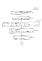
図7(a)(b)に、レーザパワー設定のための大まかな手順の2例を示した。
図7(a)は、まずDOW特性(ダイレクトオーバーライト特性)の安定化を行い、続いてフォーカスバイアス調整を行い、その後にOPC処理を行うようにしたものである。
一方図7(b)はDOW特性の安定化を行い、続いてOPC処理を行い、その後にフォーカスバイアス調整を行うようにしたものである。
【0059】
即ち本例では、少なくともDOW特性安定化を実行した後にOPC処理を行うこととしている。そしてOPC処理とフォーカスバイアス調整については、どちらが先に実行されるかにより、それぞれ異なる利点が得られるため、実際の装置ではそれを勘案して選択すればよいものとなる。
なお、DOW特性の安定化は、OPC処理又はフォーカスバイアス調整の直前であっても良いし、或る程度時間が離れた前の時点であっても良い。一方、フォーカスバイアス調整は、通常は、OPC処理の直前又は直後に行われることになる(但し離れた時点で実行されることもあり得る)。
【0060】
まずDOW特性安定化処理について説明する。
DOW特性とは、オーバーライト回数によりジッター、エラーレート、アシンメトリが変化することをいう。
例えば同様の記録動作を繰り返していくと、1回目の記録時よりも2回目の記録時はジッターがかなり悪くなるが、3回目以降は徐々にジッターの変動は小さくなり、10回目以降は安定していくことが実験により確認されている。
【0061】
図8は縦軸にジッター、横軸にオーバーライト回数をとって、ジッターのDOW特性を示したものである。
なお、ジッター値は記録パワーPw及び記録パワーPwと消去パワーPeの比によって異なるものとなり、図8では各種パワーで計測されたジッター値の範囲を示している。
この図から、初期記録に対してオーバーライト回数を重ねる毎にジッターは変動するが10回以上のオーバーライトではほぼ安定することがわかる。
【0062】
また図9は、縦軸にアシンメトリ値、横軸にオーバーライト回数をとって、アシンメトリのDOW特性を示したものである。
この場合も、図8と同様に各種パワーで計測されたアシンメトリ値の範囲を示している。
この図から、アシンメトリ値に関しても、初期記録に対してオーバーライト回数を重ねる毎にばらつきが大きいが、10回以上のオーバーライトではほぼ安定することがわかる。
【0063】
このようなDOW特性を考えると、例えばOPC処理に用いるディスク90上のドライブテストゾーン(試し書き領域)に、未記録部分と少なくとも1回以上記録を行った部分が混在すると、観測されるジッター(又はエラーレート)や、アシンメトリ値がばらつき、判別されるレーザパワーの精度が悪くなる。
【0064】
そこで本例では、OPC処理に利用するドライブテストゾーンの全域、もしくは実際に試し書きを行う一部のエリアについて、OPC処理に先だって無条件に、少なくとも2回以上、好ましくは10回以上のオーバーライトを実行する。
これが本例でいうDOW安定化処理である。
このようなDOW安定化処理を行ない、試し書きを行うエリアの特性を安定化させることで、その後、OPC処理の際にジッター/エラーレートやアシンメトリ値が、エリアによってばらつくということはなくなり、最適レーザパワーを精度良く判別できることになる。
【0065】
なお、DOW特性安定化処理については、少なくともOPC処理が実行される前の時点で、また少なくともOPC処理で試し書きを行う領域において実行されればよい。このため、DOW特性安定化の実行のタイミングや、DOW特性安定化処理の対象エリアは各種考えられる。
【0066】
DOW特性安定化の実行タイミングとしては、例えばディスク90がメーカーから出荷される前に製造工程(例えば最終の調整工程)において、インナー及びアウターのドライブテストゾーンに対して実行されるようにしても良いし、或いはユーザーサイドで記録再生装置において実行されるようにしても良い。
ユーザーサイドの記録再生装置で実行されるとした場合でも、ディスク装填時に行っても良いし、OPC処理の直前に行われるようにしても良い。また、ディスクを初めて使用する際のフォーマット時に実行されるようにしても良い。
【0067】
またDOW特性安定化処理の対象エリアとしては、インナー及びアウターのドライブテストゾーン領域の全域を対象としても良いし、インナー又はアウターのドライブテストゾーンの一方を対象としても良い。工場出荷前に実行する場合については、インナー及びアウターのドライブテストゾーン全域を対象とすることが好適である。
さらには、ユーザーサイドの記録再生装置で実行する場合は、同じくインナー、アウターのドライブテストゾーンの一方又は両方の全域を対象としても良いし、或いはその後に行われるOPC処理で実際に試し書きが行われるエリア、つまりドライブテストゾーン内の一部のエリアを対象としても良い。
これら、DOW特性安定化処理の実行タイミングや実行対象エリアの各種の例については、後述する具体的な処理例で述べる。
【0068】
本例ではこのようなDOW特性安定化処理が行われた後に、OPC処理が実行される。
OPC処理の概要は、前述したようにディスク90のドライブテストゾーンに対してレーザパワー(記録パワーPw及び消去パワーPe)を変化させながら試し書き記録を行い、それを再生してジッター/エラーレート、及びアシンメトリ値を監視して、最適な記録パワーPw、消去パワーPeを判別する処理である。
【0069】
ところが、このための具体的な処理としては、記録パワーPw、消去パワーPeとしてのそれぞれの変更可能なステップ数や、記録パワーPwと消去パワーPeの組み合わせ(さらには冷却パワーPcの組み合わせ)により、試し書きを行うレーザパワーとしては、かなりの数のバリエーションが存在する。
そして、最も高精度に記録パワーPw、消去パワーPeを判別したいのであれば、全ての組み合わせで試し書きを行って、それぞれの組み合わせでのジッター等を監視し、ジッター等が最適となる組み合わせを判別しなければならない。ところがそれはOPC処理に非常に時間がかかることを意味する。
一方、試し書きを行う際の組み合わせの数を減らしたり、或いは最適な記録パワーPwだけを判別するようにすれば、OPC処理時間は短縮できるが、最適レーザパワーとしての判別精度が低下することはいうまでもない。
【0070】
ここで本例では短時間でかつ精度の良いOPC処理を実現することを1つの目的としているが、このために、記録パワーPwと消去パワーPeの最適比、もしくは最適な組み合わせの近似式を利用して処理を行うものとしている。
【0071】
上述のDOW特性についてみてみると、ジッターやアシンメトリ値に関しては、記録時の記録パワーPwと消去パワーPeの比(Pe/Pw)に大きく依存することが実験から確認されている。つまりDOW特性においてジッターが最小となるときの比(Pe/Pw)はほとんど変化していない。
これを言い換えれば、記録パワーが変わっても、ジッターが最小となる(或いはアシンメトリ値が最適となる)記録パワーと消去パワーの比は常にほぼ一定と考えられ、従って、例えば或る記録パワー(必ずしも最適記録パワーでなくとも)に対する最適な消去パワーが見つけられれば、そのときの比(Pe/Pw)を保ちながら、記録パワーと消去パワーの組み合わせを選択し、その中で最適な記録パワー(又は記録パワーと消去パワーの組み合わせ)を見つけることで、高精度かつ短時間でOPC処理が実行できることになる。
【0072】
また、単に1つの記録パワーに対して最適消去パワーを見つけて、比を設定するのみでなく、この1つの記録パワーに対する最適消去パワーを見つける動作を複数回実行すれば、記録パワーと消去パワーの最適組み合わせの近似式が算出できる。従って、その近似式に沿って記録パワーと消去パワーの組み合わせを選択し、その中で最適な記録パワー(又は記録パワーと消去パワーの組み合わせ)を見つけることで、短時間で、さらに高精度なOPC処理が実行できる。
【0073】
上述したように本例においては、フォーカスバイアス調整については、OPC処理の直前もしくは直後で実行される。
記録時のフォーカスバイアスについては、上述したように最適な再生RF信号が得られるポイント(ジッター最小ポイント)に調整されなければならないが、記録パワーが高すぎた場合は、ジッターが最小点となるポイントが2点になる。
図10(a)〜(d)は、それそれ異なるレーザパワー(記録パワーPw、消去パワーPe、冷却パワーPc)において、ジッターとデフォーカスの関係を示している。
この図10(a)〜(d)を比較してわかるように、レーザパワーが大きい図10(d)の場合は、ジッター最小点となるボトムが2つ観測され、このため最適なフォーカスバイアスが検出できない。一方、比較的レーザパワーの小さい図10(a)〜(c)ではジッター最小点が正しく観測でき、最適なフォーカスバイアスを判別できる。
【0074】
このような事情を考慮したうえで、フォーカスバイアス調整をOPC処理の前又は後で行うことによるそれぞれの利点は次のようになる。
【0075】
まず、図7(a)のようにOPC処理に先だってフォーカスバイアス調整を行う場合については、そのフォーカスバイアス調整実行時点では最適なレーザパワーは見つけられていない。
このため、適当なレーザパワーでフォーカスバイアス調整を行うと、もしそのパワーが高すぎた場合は適切にフォーカスバイアス値を見つけられないおそれがある。
そこで、記録時のフォーカスバイアス調整を行う際には、レーザパワーを、レーザパワーの初期値(例えば平均的な値)より多少パワーの小さい値にセットして実行する。これにより、フォーカスバイアスが適切に調整できる。
そしてこの場合は、フォーカスバイアス調整後にOPC処理が行われることになるため、OPC処理においては最適なフォーカスバイアス調整での最適レーザパワーの設定が可能となるため、よりOPC処理の精度が向上される。
またフォーカスバイアスが最適化された後のOPC処理であることにより、OPC処理時に、ディスク90にダメージを与えるほどの記録パワーで記録が行われることはなくなる。
【0076】
次に、図7(b)のようにOPC処理の後にフォーカスバイアス調整を行う場合は、OPC処理によりレーザパワー最適値が既にわかっていることになるため、レーザパワーを最適値にセットしてフォーカスバイアス調整を実行できることになる。
従って、レーザパワーが高すぎてフォーカスバイアス調整がうまくいかないということもなく、さらに実際に記録に使用するレーザパワーにより調整を行うものであるため、記録動作に即した最も適切なフォーカスバイアス調整が可能となる。
【0077】
4.動作方式
4−1 DOW特性安定化処理
以下、図7に示した手順に関しての具体的な動作方式について各種の例を説明していく。
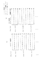
まずDOW特性安定化処理のフローチャートを図11に示す。上述したようにDOW特性安定化処理はディスク90の製造工程において実行されても良いし、ユーザーサイドの記録再生装置で実行されても良い。このため図11のフローチャートは製造工場において調整で用いる記録装置のコントローラや、ユーザーサイドにおける図3の記録再生装置のシステムコントローラ10による制御を示すものとなる(以下の説明では、システムコントローラ10の処理とする)。
なお、この図11ではディスクのインナー及びアウタードライブテストゾーンの全域を対象としてDOW特性安定化処理を行う処理例としている。
【0078】
DOW特性安定化処理を行う際には、まずシステムコントローラ10はステップF101として安定化のためのオーバーライト回数OWCをセットする。例えば2回オーバーライトを行うのであればOWC=2、10回オーバライトを行うのであればOWC=10とする。
またステップF102で変数nをn=0とする。
【0079】
以上の設定が済んだら、ステップF103で実際に内周側のドライブテストゾーンのオーバーライトを実行する。即ち1664セクターのインナードライブテストゾーンの全域に対して、所定のデータによりオーバーライトを実行する。書込の際のデータとしては、所定パターンのデータを用意しても良いし、ランダムなデータでもよい。またはDCライト/DCイレーズを実行するようにしても良い。さらにこのステップF103のオーバーライトは複数回行われることになるが、各回毎に記録データを変更させても良い。
【0080】
インナードライブテストゾーンの全域に対して一通りのオーバーライトが完了されたら、ステップF104で変数nをインクリメントし、ステップF105で変数nがオーバーライト回数OWCに達したかを確認する。そして達していなければステップF103に戻り、再びインナードライブテストゾーンの全域に対してのオーバーライトを実行する。
つまりステップF103〜F105によりインナードライブテストゾーンに対して設定したオーバーライト回数OWCだけオーバーライトが実行される。
【0081】
設定回数のオーバライトが完了したら、ステップF106に進んで変数nをゼロにリセットするとともに、ステップF107で外周側のドライブテストゾーンのオーバーライトを実行する。即ち3072セクターのアウタードライブテストゾーンの全域に対して、所定のデータによりオーバーライトを実行する。上記同様、書込の際のデータは各種考えられる。
そしてアウタードライブテストゾーンの全域に対して一通りのオーバーライトが完了されたら、ステップF108で変数nをインクリメントし、ステップF109で変数nがオーバーライト回数OWCに達したかを確認する。そして達していなければステップF107に戻り、再びアウタードライブテストゾーンの全域に対してのオーバーライトを実行する。
このステップF107〜F109によりアウタードライブテストゾーンに対して設定したオーバーライト回数OWCだけオーバーライトが実行される。そしてアウタードライブテストゾーンに対するOWC回のオーバーライトが完了したら、DOW特性安定化処理が終了される。
【0082】
このような処理により、インナー及びアウタードライブテストゾーンの全域が、DOW特性が安定化された状態となる。
【0083】
なおDOW特性安定化処理の例は他にも多様に考えられる。
まず、インナー又はアウターのドライブテストゾーンの一方のみに対してDOW特性安定化処理が実行されるようにしても良い。例えば記録再生装置におけるOPC処理が、インナー又はアウターのドライブテストゾーンの一方のみで実行される場合は、その一方のみに対してDOW特性安定化処理を実行しておけば足り、また処理効率は向上する。
また、DOW特性安定化処理がOPC処理の直前に行われる場合などは、インナー又はアウターのドライブテストゾーン内でOPC処理で用いられるエリア(試し書き実行エリア)がわかるため、その試し書き実行エリアのみに対してDOW特性安定化処理が行われればよい。もちろんこれによってDOW特性安定化処理に要する時間を短縮できる。
これら各種の処理例は、次のディスク装填時の処理例において述べる各種のDOW特性安定化処理タイミングの事情に応じて選択されればよい。
【0084】
4−2 ディスク装填時の処理例(A)〜(C)
ディスク90が記録再生装置に装填された後における、レーザパワー設定に関する各種処理例(A)(B)(C)を、図12、図13、図14でそれぞれ説明する。
【0085】
[処理例(A)]
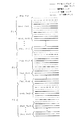
図12は処理例(A)として、ディスク90が装填された後のシステムコントローラ10の処理を示している。
【0086】
ディスク90が装填されると、システムコントローラ10はまずステップF201として、そのディスク90の種別やライトプロテクト状況を判別し、記録可能なディスクであるか否かを確認する。
例えばCD−ROM、DVD−ROMなどの再生専用ディスクであった場合や、オーバーライト可能なディスクであっても、ライトプロテクトがかけられているディスクであった場合は、そのディスクに対して記録動作が行われることはなく、従ってOPC処理も必要ないため、再生のみを対象とした通常処理に移る。
【0087】
記録可能なディスクであった場合は、ステップF202でDOW特性安定化処理の必要性を判断し、必要であればステップF203で例えば上述したようなDOW特性安定化処理を行う。
必要でない場合とは、工場出荷前にすでにDOW特性安定化処理が施されている場合や、そのディスクに対する最初のフォーマット時にDOW特性安定化処理を施した場合である。さらには、後述するようにOPC処理の直前にDOW特性安定化処理を実行する場合も、ここではDOW特性安定化処理を実行する必要はない。
なお従って、ディスク装填の際にまずDOW特性安定化処理を実行するという動作方式が採用されていなければ、このステップF202,F203の処理自体が不要となる。このため図12の処理として括弧を付したステップF202,F203が存在しない処理例も考えられる(これは後述する図13、図14でも同様)。
【0088】
また、装填されたディスクが過去において記録再生装置に装填されたときにDOW特性安定化処理が実行された場合も、改めてDOW特性安定化処理を行う必要はない。
【0089】
この図12以降で説明していく各種処理例において、予めこの点を整理しておくと次のようになる。
ディスク90が工場出荷前、もしくは記録再生装置で最初にフォーマットされる時点でDOW特性安定化がドライブテストゾーンの全域に対して必ず実行されることとした場合は、図12、図13、図14、及び図16、図17に示されるDOW特性安定化処理は全て不要である。
【0090】
出荷前やフォーマット時にDOW特性安定化が実行されないのであれば、例えば図12〜図14のように装填直後に必要に応じて(つまり過去に1度も実行されていなければ)実行することが考えられるが、上記のようにOPC処理の直前にDOW特性安定化処理を実行する場合は、装填直後のDOW特性安定化は不要である。逆に、OPC処理の直前にDOW特性安定化処理を実行しない場合には、図12〜図14のように装填直後に必要に応じて実行することとなる。
【0091】
ところで、例えば図12のステップF202などで、DOW特性安定化の必要性を判断する方法としては次のような方法が考えられる。
まず、ドライブテストゾーンに過去にまったく記録が行われていない未記録領域の存在を確認する方法がある。
或いは、DOW特性安定化を実行したら、その実行済のフラグ情報をディスクの所定のエリアに記録しておき、ステップF202等ではそのフラグを確認するという手法も考えられる。
さらに、後述するようにテストゾーン管理テーブルを記録するようにすれば、より詳細に(例えばドライブテストゾーン内のエリア毎に)DOW特性安定化の実行済の有無を確認できる。
これら各種の手法が考えられるが、具体的には、DOW特性安定化の実行タイミングや実行対象エリアなどの設定の事情に応じて決定されることになる。
【0092】
図12の処理では、ディスク装填後ステップF204に進んだら、通常処理となる。このステップF204でいう通常処理とは、記録動作以外の、例えばホストコンピュータ100との通信や、再生動作などをいう。
ステップF204での通常処理中に、記録動作要求、つまり装填後第1回目の記録動作がホストコンピュータ100から要求された場合は、システムコントローラ10はステップF205からF206に進み、まず記録時のためのフォーカスバイアス調整を実行させる。これは、図7(a)で述べたOPC処理前のフォーカスバイアス調整となる。
【0093】
続いてステップF207でOPC処理を実行し、最適な記録パワー、消去パワーを設定する。具体的なOPC処理例については各種の例があるため、それぞれ後述する。
そして、フォーカスバイアス調整及びOPC処理により最適なバイアス及びレーザパワーを設定したら、ステップF208としての通常処理に進む。ここでの通常処理とは、記録動作を含んで、ホストコンピュータ100からの指示に応じて実行される各種動作である。
そしてステップF206,F207の処理が行われたのは、ホストコンピュータ100からのライトコマンドに応じたものであるため、ステップF208ではまず要求された記録動作を実行する。
その記録動作が完了した後は、このステップF208において、ホストコンピュータ100の指示に応じて記録動作や再生動作を実行することになる。
【0094】
ところで、ステップF208の通常処理の段階で、ステップF209において所定時間の経過、又は所定値以上の温度変化が検出された場合は、再度ステップF204、F205のループに進み、記録動作要求が発生した時点でステップF206、F207のフォーカスバイアス調整及びOPC処理を行うことになる。
【0095】
後述するがOPC処理が実行された時点でシステムコントローラ10の内部タイマ10aがリセット/スタートされることで、システムコントローラ10は或るOPC処理後の経過時間を知ることができる。そして、そのカウントされている経過時間が所定時間以上となったら、その後記録が実行される場合は、フォーカスバイアス及びレーザパワーの再設定を行うようにしているものである。
また、システムコントローラ10は、温度センサ24からの装置内の温度値を監視しており、OPC処理が実行された時点で装置内温度を記憶するようにしており(後述)、その後のステップF208の通常処理中も温度の監視を続けることで、装置内温度がOPC処理時と比べて所定値以上変化したか否かを判断できるようにしている。そして所定値以上の温度変化があった場合は、再度ステップF204、F205のループに進み、記録動作要求が発生した時点でF206、F207のフォーカスバイアス調整及びOPC処理を行なってフォーカスバイアス及びレーザパワーの再設定を行うようにしている。
【0096】
以上のような処理例(A)によれば、次のような効果が得られる。
・DOW特性安定化後にOPC処理が行われることで、レーザパワー設定精度が向上される。
・フォーカスバイアス調整後にOPC処理が行われることで、レーザパワー設定精度が向上される。
・記録時のフォーカスバイアスも最適化されるため記録特性が向上する。
・装填後の初回の記録動作時の直前、もしくは所定時間経過後の記録動作時の直前、もしくは温度変化後の記録動作時の直前にOPC処理が行われることになるが、これは最低限必要な時のみにOPC処理が行われることを意味し、無駄なOPC処理が実行されない。つまりOPC処理が効率的に実行される。フォーカスバイアス調整も同様である。
・OPC処理後、所定時間を経過した後において再度記録動作が行われる場合には、再度フォーカスバイアス調整及びOPC処理が行われることで、経時変化に対応して常に最適なレーザパワー及びフォーカスバイアス状態で記録が実行でき、記録動作性能が安定する。
・OPC処理後、所定値以上の温度変化が確認され、その後において再度記録動作が行われる場合には、再度フォーカスバイアス調整及びOPC処理が行われることで、温度変化があってもそれに対応して常に最適なレーザパワー及びフォーカスバイアス状態で記録が実行でき、記録動作性能が安定する。
【0097】
[処理例(B)]
続いて図13で処理例(B)を説明する。
この処理例(B)では、ステップF301〜F305、及びステップF308,F309は、上記処理例(A)におけるステップF201〜F205、及びステップF208,F209と同様であるため重複説明を避ける。
処理例(A)と異なる点は、ステップF306のOPC処理及びステップF307のフォーカスバイアス調整に手順であり、即ちこの処理例(B)の場合は、ディスク装填後の最初の記録動作が実行される直前に(又は所定時間経過後もしくは所定値以上の温度変化が確認された後において記録動作が実行される直前に)、まずOPC処理を行って、その後にフォーカスバイアス調整を行うものとなる。つまり図7(b)の手順に沿った方式である。
【0098】
従って記録動作の開始直前には、まずステップF306でOPC処理を実行し、最適な記録パワー、消去パワーを設定する(具体的なOPC処理例については後述)。
そして、最適な記録パワー、消去パワーが判別された後で、ステップF307では、その最適な記録パワー、消去パワーを用いてフォーカスバイアス調整を行うことになる。
【0099】
このような処理例(B)によれば、次のような効果が得られる。
・処理例(A)と同様に、DOW特性安定化後にOPC処理が行われることで、レーザパワー設定精度が向上される。
・処理例(A)と同様に、記録時のフォーカスバイアスも最適化されるため記録特性が向上する。
・OPC処理後に最適レーザパワーでフォーカスバイアス調整が行われることで、フォーカスバイアスが、実際の記録動作時の状況に即した状態で調整され、記録時のフォーカスバイアスはより最適化されるため記録特性が向上する。
・処理例(A)と同様に、装填後の初回の記録動作時の直前、もしくは所定時間経過後の記録動作時の直前、もしくは温度変化後の記録動作時の直前にOPC処理が行われることになるが、これは最低限必要な時のみにOPC処理が行われることを意味し、無駄なOPC処理が実行されない。つまりOPC処理が効率的に実行される。フォーカスバイアス調整も同様である。
・処理例(A)と同様に、OPC処理後、所定時間を経過した後において再度記録動作が行われる場合には、再度フォーカスバイアス調整及びOPC処理が行われることで、経時変化に対応して常に最適なレーザパワー及びフォーカスバイアス状態で記録が実行でき、記録動作性能が安定する。
・処理例(A)と同様に、OPC処理後、所定値以上の温度変化が確認され、その後において再度記録動作が行われる場合には、再度フォーカスバイアス調整及びOPC処理が行われることで、温度変化があってもそれに対応して常に最適なレーザパワー及びフォーカスバイアス状態で記録が実行でき、記録動作性能が安定する。
【0100】
[処理例(C)]
続いて図14で処理例(C)を説明する。
この処理例(C)が上記処理例(A)(B)と大きく異なる点は、OPC処理やフォーカスバイアス調整が記録動作の直前でなく、基本的にはディスク装填時に実行されることである。
【0101】
ディスク90が装填されると、システムコントローラ10はまずステップF401として、そのディスク90の種別やライトプロテクト状況を判別し、記録可能なディスクであるか否かを確認する。
また記録可能なディスクであれば、ステップF402、F403で必要に応じてDOW特性安定化処理を行う。
ここまでは上記処理例(A)(B)と同様である。
【0102】
続いてステップF404に進むわけであるが、このステップF404に進むのはディスク装填直後の時点となる。
そしてステップF404でシステムコントローラ10は、記録時のためのフォーカスバイアス調整を実行させる。
【0103】
続いてステップF405でOPC処理を実行し、最適な記録パワー、消去パワーを設定する(具体的なOPC処理例は後述)。
そして、フォーカスバイアス調整及びOPC処理により最適なバイアス及びレーザパワーを設定したら、ステップF406としての通常処理に進む。ここでの通常処理とは、ホストコンピュータ100からの指示に応じて実行される各種動作、つまり記録、再生、消去、通信等の通常の全ての処理を意味している。
従ってステップF406,F407のループ期間においてホストコンピュータ100から記録要求が発せられた場合は、ステップF406で要求された記録動作を実行する。このとき、レーザパワー及びフォーカスバイアスは当然ながらそれより前の時点でステップF404,F405で設定された値とされる。
またもちろん、ステップF406,F407のループ期間においてホストコンピュータ100から再生動作要求があった場合は、ステップF406で再生動作が実行される。
【0104】
ところで、ステップF406の通常処理の段階で、ステップF407において所定時間の経過、又は所定値以上の温度変化が検出された場合は、再度ステップF404に進み、ステップF404,F405のフォーカスバイアス調整及びOPC処理を行うことになる。時間経過及び温度変化の監視方式は処理例(A)で説明した方式と同様である。
この点で上記処理例(A)(B)と異なるのは、上記処理例(A)(B)では、時間経過又は温度変化の検出後において、記録動作要求が発生された時点でフォーカスバイアス調整及びOPC処理を行うことに対し、この処理例(C)では、時間経過又は温度変化の検出があったら、その時点でフォーカスバイアス調整及びOPC処理を行うことにある。
【0105】
このような処理例(C)によれば、次のような効果が得られる。
・処理例(A)(B)と同様に、DOW特性安定化後にOPC処理が行われることで、レーザパワー設定精度が向上される。
・処理例(A)(B)と同様に、記録時のフォーカスバイアスも最適化されるため記録特性が向上する。
・処理例(A)と同様に、フォーカスバイアス調整後にOPC処理が行われることで、レーザパワー設定精度が向上される。
・装填直後、もしくは所定時間経過直後、もしくは温度変化検出直後にOPC処理が行われることになるため、記録動作が要求される時点では、既に最適なレーザパワー及びフォーカスバイアスが設定されていることになる。従って、記録動作要求に対して直ちに記録動作を開始することができ、レスポンスの良い記録動作を実現できる。
・OPC処理後、所定時間を経過した後において、再度フォーカスバイアス調整及びOPC処理が行われることで、経時変化に対応して常に最適なレーザパワー及びフォーカスバイアス状態で記録が実行でき、記録動作性能が安定する。
・OPC処理後、所定値以上の温度変化が確認された場合に、再度フォーカスバイアス調整及びOPC処理が行われることで、温度変化があってもそれに対応して常に最適なレーザパワー及びフォーカスバイアス状態で記録が実行でき、記録動作性能が安定する。
【0106】
なお、この処理例(C)はフォーカスバイアス調整後にOPC処理を行うという、図7(a)の手順に沿ったものであるが、図7(b)の手順に沿った処理例も考えられる。つまり、図14のステップF404とF405が逆になる処理例である。
その場合は、上記処理例(B)と同様に、OPC処理後に最適レーザパワーでフォーカスバイアス調整が行われることで、フォーカスバイアスが、実際の記録動作時の状況に即した状態で調整され、記録時のフォーカスバイアスはより最適化されるため記録特性が向上するという効果が得られる。
【0107】
4−3 OPC処理例(I)〜(III)
次に、各種OPC処理例として3つの処理例(I)(II)(III)をそれぞれ図15、図16、図17で説明する。このOPC処理例(I)〜(III)は、上記図12、図13、図14の各ディスク装填後の処理例において、ステップF207,F306,F405で実行されるOPC処理のバリエーションとなる。
【0108】
[処理例(I)]
図15はOPC処理例(I)としてのシステムコントローラ10の処理を示している。この場合は、システムコントローラ10はまずステップF501としてOPC動作を行う。OPC動作とは、前述してきているように、ディスク90のドライブテストゾーンに対してレーザパワーを変化させながら試し書きを行い、その再生情報からジッター等を監視して最適な記録パワー、消去パワーを設定する動作であるが、この具体的な動作手順も各種の例が考えられるため、OPC動作例(1)〜(4)としてまとめて後述する。
【0109】
OPC動作により最適な記録パワー、消去パワーが設定されたら、ステップF502で、内部タイマ10aのリセット/スタートを行なう。つまりOPC動作からの経過時間のカウントを開始する。また、その時点で温度センサ24から得られる装置内温度を記憶する。
以上の処理を完了したら、OPC処理、つまり上記図12のステップF207、又は図13のステップF306、又は図14のステップF405の処理を終える。
【0110】
ステップF502でのタイマリセット/スタート及び装置内温度の記憶は、上述した図12のステップF209、又は図13のステップF309、又は図14のステップF407の判別のための処理となる。つまり上述したように、OPC処理後において所定時間が経過した場合、又は所定値以上の温度変化が検出された場合に、再度OPC処理及びフォーカスバイアス調整を実行できるようにするための処理となる。
【0111】
このようなOPC処理例(I)により、上記ディスク装填後の処理例(A)〜(C)の効果として説明したように、常に最適なレーザパワーで記録が実行できるという効果が実現される。
【0112】
[処理例(II)]
図16はOPC処理例(II)としてのシステムコントローラ10の処理を示している。
この場合は、システムコントローラ10はまずステップF511として、ドライブテストゾーンに関してDOW特性安定化処理の必要があるか否かを判別する。
上述したように、DOW特性安定化処理の実行タイミングは各種考えられるが、このDOW特性安定化処理の実行タイミングを、OPC動作の直前に行うものと設定される場合は、この図16のようにOPC処理に進んだ時点で、DOW特性安定化処理の必要性を判断し、必要であればステップF512で上述したようなDOW特性安定化処理を行う。
OPC動作直前にこのような必要に応じたDOW特性安定化処理を行う処理手順を付加することの必要性、及びステップF511でのDOW特性安定化処理の必要性の判断方式は、上述したとおりである。
【0113】
必要に応じてDOW特性安定化処理が行われた後は、ステップF513としてOPC動作を行う(OPC動作例は後述)。
そしてOPC動作により最適な記録パワー、消去パワーが設定されたら、上記OPC処理例(I)と同様に、ステップF514で、内部タイマ10aのリセット/スタート、及び温度センサ24から得られる装置内温度の記憶を行なう。
以上の処理を完了したら、OPC処理、つまり上記図12のステップF207、又は図13のステップF306、又は図14のステップF405の処理を終える。
【0114】
このようなOPC処理例(II)により、上記ディスク装填後の処理例(A)〜(C)の効果として説明したように、常に最適なレーザパワーで記録が実行できるという効果が実現される。
また、このOPC処理においてOPC動作直前にDOW特性安定化処理が行われることは、製造工程やディスクフォーマット時、或いは、図12、図13、図14に示した時点でDOW特性安定化処理を行うことが不要となることを意味する。換言すれば、最低限必要なときのみDOW特性安定化処理が実行されるということになる。
【0115】
[処理例(III)]
図17はOPC処理例(III)としてのシステムコントローラ10の処理を示している。
この処理例(III)は、上記処理例(II)と同様に、このOPC処理過程でDOW特性安定化を行うとともに、そのDOW特性安定化処理は、ドライブテストゾーンの一部、つまり実際に試し書きを行う使用エリアのみ(もしくは少なくともその使用エリアを含む一部の領域)に対して実行されるようにしたものである。
【0116】
まずステップF521では、システムコントローラ10は装填されているディスク90のドライブテストゾーンのうちで、実際にOPC動作において試し書きを行うエリア(以下「OPC使用エリア」という)を選択する。
なおこの選択処理については、処理例(イ)(ロ)(ハ)として後述する。
【0117】
そしてOPC使用エリアを選択したら、ステップF522で、その選択されたOPC使用エリアについてDOW特性安定化処理の必要があるか否かを判別する。つまりここでは、ドライブテストゾーン内の一部であるOPC使用エリアのみを対象として、既にDOW特性が安定化されているか否かを確認することとなる。そして必要であればステップF523で、その選択されたOPC使用エリアのみについて(もしくは少なくとも選択されたOPC使用エリアを含むテストゾーン内の一部の領域について)、DOW特性安定化処理を行う。
OPC動作直前にこのような必要に応じたDOW特性安定化処理を行う処理手順を付加することの必要性、及びステップF522でのOPC使用エリアのDOW特性安定化処理の必要性の判断方式は、上述したとおりである。
【0118】
必要に応じて少なくともOPC使用エリアについてDOW特性安定化処理が行われた後は、ステップF524としてOPC動作を行う(OPC動作例は後述)。
そしてOPC動作により最適な記録パワー、消去パワーが設定されたら、上記OPC処理例(I)(II)と同様に、ステップF525で、内部タイマ10aのリセット/スタート、及び温度センサ24から得られる装置内温度の記憶を行なう。
以上の処理を完了したら、OPC処理、つまり上記図12のステップF207、又は図13のステップF306、又は図14のステップF405の処理を終える。
【0119】
このようなOPC処理例(III)により、上記ディスク装填後の処理例(A)〜(C)の効果として説明したように、常に最適なレーザパワーで記録が実行できるという効果が実現される。
またOPC処理例(II)と同様に、このOPC処理においてOPC動作直前にDOW特性安定化処理が行われることは、製造工程やディスクフォーマット時、或いは、図12、図13、図14に示した時点でDOW特性安定化処理を行うことが不要となることを意味する。つまり最低限必要な時のみDOW特性安定化処理が行われる。
さらにこの場合は、DOW特性安定化処理は、最低限必要なエリア、つまりOPC使用エリアに対して行われるものとなるため、DOW特性安定化処理における複数回のオーバーライト動作の時間がかなり短縮できることになり、最も効率的な動作となる。
【0120】
4−4 OPC使用エリア選択処理例(イ)〜(ハ)
上記図17のOPC処理例(III)が採用される場合は、そのステップF521としてOPC使用エリアの選択処理が必要になる。このステップF521でのOPC使用エリア選択処理として処理例(イ)(ロ)(ハ)を図18、図20、図21に示し、また図19、図21、図22を利用して説明する。
【0121】
[処理例(イ)]
図18はOPC使用エリア選択処理例(イ)としてのシステムコントローラ10の処理を示している。
OPC使用エリアを選択する際には、まずシステムコントローラ10はステップF601として、試し書きを実行するセクター数を変数SNとしてセットする。試し書きに用いるセクター数は、実行するOPC動作方式(後述)により予めわかるものである。
【0122】
続いてステップF602で、ドライブテストゾーンの開始セクターのアドレスを変数SAにセットし、またドライブテストゾーンの終了セクターの次のアドレスより変数SNだけ前のアドレスを変数SEにセットする。
【0123】
そしてステップF603で、セクターアドレスSA〜セクターアドレスSEの間のアドレスとして、ランダムに或るセクターアドレスを選択し、選択したアドレスを変数USとする。
そしてステップF604で、セクターアドレスUSからセクターアドレス(US+SN)までの範囲を、OPC使用エリアと設定する。
【0124】
このOPC使用エリア選択処理例(イ)を模式的に示すと図19のようになる。例えばインナードライブテストゾーンの一部をOPC使用エリアとする場合、図示するように変数SA=「30600h」、変数SE=「30C80h−SN」となる(図2参照)。なおインナードライブテストゾーン内を区切っている破線はセクター単位の区切りであるとする。
【0125】
そしてアドレスSA〜SEの範囲でランダムに或るアドレスを選択してアドレスUSとする際に、選択されたアドレスが図示するアドレスUS(1)であったとすると、このアドレスUS(1)〜アドレス(US(1)+SN)がOPC使用エリアとなる。
また、例えば選択されたアドレスが図示するアドレスUS(2)であったとすると、アドレスUS(2)〜アドレス(US(2)+SN)がOPC使用エリアとなる。
【0126】
このように、OPC使用エリア選択処理例(イ)では、選択処理が行われる毎に、OPC使用エリアがドライブテストゾーンの範囲内でランダムに設定されることになる。
そして上述した図17のOPC処理例(III)では、このようにして選択されたOPC使用エリアに対して、必要に応じてDOW特性安定化処理を行った後、OPC動作を実行する。
【0127】
このOPC使用エリア選択処理例(イ)により、OPC動作において試し書きが行われるエリアが、OPC動作毎に変更されることになるため、OPC動作の毎に同じエリアばかりが試し書きされ、その部分が集中的に劣化が進行してしまうということを避けることができる。
【0128】
[処理例(ロ)]
図20はOPC使用エリア選択処理例(ロ)としてのシステムコントローラ10の処理を示している。
この例も、OPC処理が行われる度に、OPC使用エリアがランダムに選択されるものであるが、あらかじめドライブテストゾーン内でエリアを分割設定している方式となる。
【0129】
例えば図23(a)のように、インナードライブテストゾーンを複数のエリアAR1〜AR(n)に分割設定しておく。各エリアは、例えば、1回のOPC動作で試し書きが行われるセクター数以上のエリア長とする。
またディスク90上には、例えば図23(b)に示すようなテストゾーン管理テーブルを記録し、システムコントローラ10はこれを読み出してテーブル内容を確認できるようにする。
【0130】
テストゾーン管理テーブルは、各エリアAR1〜AR(n)についての情報を記録するものとし、例えば図示するように過去の試し書き回数(OPC動作に利用された総回数)を記録するようにする。さらに、図23(a)のようにドライブテストゾーンの一部に傷や汚れなどのディフェクト部分DFAが存在した場合は、図23(b)のようにそのディフェクトが存在するエリアの情報を、「Defect」として欠陥部分を含む領域である(つまりOPC使用エリアとして不適切なエリアである)ことが判別できるようにしても良い。
【0131】
このようなテストゾーン管理テーブルは、一例としては、図22に示すディスクコントロールECCブロックとしてのエリアを利用してディスク90に書き込む。
このディスクコントロールECCブロックは、図2に示したインナー及びアウターのディスクアイデンティフィケーションゾーン内に記録されるブロックであり、図22に示すように16セクター(セクター0〜セクター15)のブロックとして記録内容が定義されている。
詳しい記録内容については本発明と直接関係しないため説明を省略するが、図22からわかるように、ディスクコントロールECCブロックのセクター0のバイトポジションD40〜D2048、及びセクター1〜15の全バイトポジションはリザーブ(予備)とされている。そこで、この領域を利用すれば、ディスク90にテストゾーン管理テーブルを書き込むことができる。
【0132】
このようなテストゾーン管理テーブルをディスク90に記録するようにし、システムコントローラ10がそれを参照することで、図20のようなOPC使用エリア選択処理が可能となる。
まずシステムコントローラ10は、ステップF611として、テストゾーン管理テーブルに管理されている各エリアAR1〜AR(n)の中で、或る1つのエリアをランダムに選択する。
続いてステップF612では、選択したエリアのテーブルデータを確認し、そのエリアがディフェクトを含むエリアであるか否かを確認する。
もしディフェクトを含むエリアであれば、ステップF611に戻って再度エリアをランダムに選択する。
【0133】
ランダムに選択したエリアがディフェクトを含むエリアでなければ、ステップF613に進んで、その選択したエリアをOPC使用エリアとして設定する。
【0134】
このように、OPC使用エリア選択処理例(ロ)では、選択処理が行われる毎に、OPC使用エリアがドライブテストゾーンの範囲内でランダムに設定され、上述した図17のOPC処理例(III)では、このようにして選択されたOPC使用エリアに対して、必要に応じてDOW特性安定化処理を行った後、OPC動作を実行する。
【0135】
このOPC使用エリア選択処理例(ロ)により、OPC動作において試し書きが行われるエリアが、OPC動作毎に変更されることになるため、OPC動作の毎に同じエリアばかりが試し書きされ、その部分が集中的に劣化が進行してしまうということを避けることができる。
さらにこの場合は、ディフェクトを含むエリアがOPC使用領域となることが回避されるため、OPC動作の精度を向上させることができる。(なおディフェクトのOPC動作への影響、及びこれ以外のディフェクトキャンセル方式については後述する)
【0136】
なお、上述した図17のOPC処理例(III)では述べなかったが、このOPC使用エリア選択処理例(ロ)、及び次に説明するOPC使用エリア選択処理例(ハ)が採用される場合は、OPC動作やディフェクトの発見などに応じてディスク90上のテストゾーン管理テーブルが更新されていく必要がある。
このため例えば図17でステップF524のOPC動作が行われた後の或る時点で、使用されたエリアに対応する試し書き回数が更新されるように、テストゾーン管理テーブルが書き換えられる。
また、DOW特性安定化処理時や、OPC動作時において或るエリアでディフェクトが発見される場合もあるが、その様な場合も、そのエリアがディフェクトエリアとされるように、テストゾーン管理テーブルが書き換えられることになる。なお、各エリアAR1〜AR(n)がディフェクトエリアであるか否かの情報は、例えばディスク上のDMA(ディフェクトマネージメントエリア:図2参照)から得、それに応じてテストゾーン管理テーブルを作成又は更新するようにしても良い。
【0137】
ところで、図20の処理例(ロ)においては、OPC使用エリアとされるのは必ずしも1つのエリアとは限らない。1つのエリアのエリア長の設定及びOPC動作で試し書きを行うのに必要なエリア長に設定によるものとなるが、OPC使用エリアとして、エリアAR1〜AR(n)のうちの複数が必要になる場合もあり得る。その場合は、ランダムに選択した1つのエリアを起点として、物理的に連続する必要数のエリアをOPC使用エリアとしても良いし、特に物理的な連続性を考慮しない場合は、必要数のエリアをそれぞれランダムに選択して、それらをOPC使用エリアとしても良い。
【0138】
[処理例(ハ)]
図21はOPC使用エリア選択処理例(ハ)としてのシステムコントローラ10の処理を示している。
この例も、OPC処理が行われる度に、異なるOPC使用エリアが選択されるものであるが、その選択はランダムなものとはせずに、上記テストゾーン管理テーブルを参照して好適なエリアを選択するものである。
【0139】
まずシステムコントローラ10は、ステップF621として、テストゾーン管理テーブルに管理されている各エリアAR1〜AR(n)について、ディフェクトが存在すると記されているエリアを除いて、過去の試し書き回数が最小のエリアを抽出する。
ここで、OPC使用エリアとして必要なエリアがエリアAR1〜AR(n)の内の1つであるとした場合は、ステップF622で試し書き回数が最小となるエリア(抽出エリア)が複数個存在したら、ステップF623で、その中の1つをランダムに選択する。
そしてステップF624で、抽出エリア(もしくはステップF623で選択されたエリア)を、OPC使用エリアとして設定する。
【0140】
このように、OPC使用エリア選択処理例(ハ)では、選択処理が行われる毎に、過去の試し書き回数が最小回数のエリアがOPC使用エリアとして設定されるため、OPC動作の毎に同じエリアばかりが試し書きされ、或るエリアが集中的に使用されて劣化が進行してしまうということを避けることができる。また、ランダムな選択に比べて効率よく、満遍なく各エリアが使用されるという利点もある。
もちろんこの場合も、ディフェクトを含むエリアがOPC使用領域となることが回避されるため、OPC動作の精度を向上させることができる。
【0141】
なお、複数のエリアをOPC使用エリアとする場合は、ステップF621で試し書き回数が少ない方から必要数のエリアが抽出されることになる。そして、過去の試し書き回数が同数となるエリアの存在などにより、その抽出の結果として必要数より多いエリアが抽出された場合は、ステップF623の処理が行われるようにすればよい。
【0142】
以上、OPC使用エリア判別処理例(イ)(ロ)(ハ)について述べたが、これらのOPC使用エリア判別処理は、必ずしも上述した図17のOPC処理例(III)が採用される場合のみに実行されるものではない。
例えば図17の変形例として、ステップF522、F523が存在しない処理例も考えられるが、そのような場合にも、OPC使用エリア判別処理例(イ)(ロ)(ハ)のいずれかが実行されることもあり得る。
【0143】
また上述したテストゾーン管理テーブルは、OPC使用エリアの判別だけでなく、図17のステップF522や、図12〜図14にあげた、DOW特性安定化処理の必要性の判断に用いることもできる。
即ち試し書き回数が記述されていることから、各エリア(或いはテストゾーン全体として)のDOW安定化状況を判断できるためである。
【0144】
4−5 ディフェクトキャンセル方式
具体的なOPC動作例については後述することになるが、OPC動作の実行時には、試し書きを行った部分の再生情報からジッター/エラーレート、及びアシンメトリ値の検出を行って、最適なレーザパワーを判断することになる。
このとき、試し書きを行った部分にディフェクトが存在すると、ジッター/エラーレート、及びアシンメトリ値が正確に検出できないものとなり、ひいては最適なレーザーパワーの判別に悪影響を与えてしまう。
【0145】
図24はRF信号へのディフェクトの影響を示している。例えばディフェクトがない部分の再生RF信号が図24(a)のように観測されることに比べて、ディフェクトが存在する部分では、図24(b)のようにRF信号波形のエンベロープが大きく変動する。これによってジッターやアシンメトリ値が不正確に検出されてしまう。
このため、OPC動作時には、ディフェクト部分において試し書きを行うことを避けるか、もしくはディフェクト部分で試し書きを行ったとしても、ジッターやアシンメトリ値の算出の際に、そのディフェクト部分からの再生情報を排除する必要がある。なお本例ではこれらの動作をまとめてディフェクトキャンセルと呼ぶこととする。
【0146】
ディフェクトキャンセル方式の1つとして、ディフェクト部分において試し書きを行うことを避けるようにする方式は、上記図20、図21のOPC使用エリア選択処理例(ロ)(ハ)で述べた方式である。
つまり予めディフェクト部分を避けてOPC動作を行うようにすることで、ディフェクトキャンセルが達成される。
【0147】
一方、OPC動作中でのディフェクトキャンセル方式としては、試し書き下部分を再生する際に、ディフェクト部分の再生情報を、ジッタやアシンメトリの算出のためのサンプルから排除する方式が考えられる。以下、このような方式としての各種の例を説明していく。
【0148】
図25に、図3に示した検出部23の構成例(構成例(α))を示す。
この構成例(α)では、検出部23は、ディフェクト検出回路31、スイッチ32、ジッタ検出回路(又はエラーレート検出回路:以下同様)33、アシンメトリ検出回路34が設けられている。
そしてRFアンプ9から出力されるRF信号はディフェクト検出回路31及びスイッチ32の各端子に供給される。またスイッチ32の各端子はそれぞれジッタ検出回路33及びアシンメトリ検出回路34に接続される。
【0149】
ジッタ検出回路33は、スイッチ32を介して供給されたRF信号について、所要期間のサンプルを取り込み、RF信号のジッター(又はエラーレート)を計測してその結果をジッター(又はエラーレート)の検出値DJとしてシステムコントローラ10に供給する。
またアシンメトリ検出回路34は、スイッチ32を介して供給されたRF信号について、所要期間のサンプルを取り込み、RF信号のアシンメトリ値を計測してその結果を検出値DASとしてシステムコントローラ10に供給する。
【0150】
システムコントローラ10は、後にOPC動作の説明で述べるように、このようにして供給される検出値DJ,DASから、各レーザパワーにおける信号品質をチェックし、最適なレーザパワーを判別することになる。
【0151】
ここで、ディフェクト検出回路31は、RF信号上でのディフェクトの影響があらわれている期間を検出し、ディフェクト検出信号DFをスイッチ32に対して出力する。
即ちディフェクト検出回路31には、図24(b)のようにRF信号振幅に対する所定のスレッショルド値Refが設定されており、入力されてくるRF信号とスレッショルド値Refを比較することで、図24(c)のようなディフェクト検出信号DFを発生させる。
そしてスイッチ32は、ディフェクト検出信号DFがオンとなった期間は、各接点を開き、その期間はRF信号がジッタ検出回路33及びアシンメトリ検出回路34に供給されないようにする。
【0152】
即ち検出部23がこのように構成されることで、ジッタ検出回路33及びアシンメトリ検出回路34にはディフェクトの影響があらわれた期間のRF信号は供給されず、従って検出値DJ、DASには、ディフェクトの影響はあらわれないことになる。これによってシステムコントローラ10は検出値DJ、DASにより正しく信号品質をチェックできることになり、ハードウエア的なディフェクトキャンセルが実現される。
【0153】
同じく、ディフェクトキャンセルを実現するための検出部23の構成例(構成例(β))を図26に示す。
この構成例(β)では、検出部23は、ディフェクト検出回路31、ジッタ検出回路(又はエラーレート検出回路:以下同様)33、アシンメトリ検出回路34が設けられている。
そしてRFアンプ9から出力されるRF信号はディフェクト検出回路31、ジッタ検出回路33、アシンメトリ検出回路34のそれぞれに供給される。ディフェクト検出回路31、ジッタ検出回路33、アシンメトリ検出回路34の動作は上記構成例αの場合と同様であり、所要の信号処理により、それぞれディフェクト検出信号DF、検出値DJ、検出値DASを出力する。そしてこの例の場合は、ディフェクト検出信号DF、検出値DJ、検出値DASが、システムコントローラ10に供給される。
【0154】
この構成例(β)の場合は、検出部23においてハードウエア的にディフェクトキャンセルを実現するのではなく、システムコントローラ10側でソフトウエア的にディフェクトキャンセルを行うものである。
このため、検出部23からディフェクト検出信号DF、検出値DJ、検出値DASが供給され、これを取り込む際の処理として、システムコントローラ10は図27のような処理(処理(β−1))を行う。
【0155】
つまり、検出値DJ又はDASが供給され、1つのサンプルとして取り込まれるタイミングとなる毎に、処理をステップF701からF702に進め、そのときディフェクト検出信号DFがオンとなっているか否かを確認する。
そしてディフェクト検出信号DFがオフであれば、ステップF703に進んで、供給された検出値DJ又はDASを信号品質のチェックのための計算用サンプルとして記憶する。ところがディフェクト検出信号DFがオンであった場合は、ステップF703には進まず、つまりその時点で供給された検出値DJ又はDASは計算用サンプルとはしないようにする。
【0156】
このような処理(β−1)により、システムコントローラ10は、供給される検出値DJ,DASのうちで、ディフェクトの影響があらわれた期間の検出値DJ,DASを計算対象から排除することになり、ソフトウエア的なディフェクトキャンセルが実現される。
なお、実際には、ジッタ検出回路33やアシンメトリ検出回路34の処理方式などの影響で、ディフェクト検出信号DFがオンになるタイミングと、ディフェクトの影響があらわれた検出値DJ又はDASが供給されるタイミングがずれることがあり得るため、システムコントローラ10はステップF702の判断で、そのタイミングのずれを考慮する必要がある。
【0157】
ところで、図26の構成例βのように、ディフェクト検出信号DFがシステムコントローラ10に供給されるようにした場合、システムコントローラ10が予めドライブテストゾーン内のディフェクト部分を検査し、それを記憶しておくことができる。
つまり、例えばOPC動作に先立って、ある時点でドライブテストゾーンの再生を行ないながらディフェクト検出信号DFを監視し、ディフェクトが存在したら、そのアドレスを内部RAMなどに記憶しておくことができる。
【0158】
その様な動作方式を採用する場合は、図28の処理例(β−2)によっても、ソフトウエア的なディフェクトキャンセルが可能となる。
つまり、検出値DJ又はDASが供給され、1つのサンプルとして取り込まれるタイミングとなる毎に、処理をステップF711からF712に進め、そのときの検出値DJ又はDASの計算対象となったRF信号の再生エリアのアドレスを確認する。そして、その再生エリアのアドレスが、記憶しておいたディフェクト部分のアドレスであるか否かを判別する。
【0159】
そしてディフェクト部分のアドレスでなければ、ステップF713に進んで、供給された検出値DJ又はDASを信号品質のチェックのための計算用サンプルとして記憶する。一方、ディフェクト部分のアドレスであった場合は、ステップF713には進まず、つまりその時点で供給された検出値DJ又はDASは計算用サンプルとはしないようにする。
【0160】
このような処理例(β−2)により、システムコントローラ10は、供給される検出値DJ,DASのうちで、ディフェクトの影響があらわれた期間の検出値DJ,DASを計算対象から排除することになり、ソフトウエア的なディフェクトキャンセルが実現される。
【0161】
ところで、この処理例(β−2)によるディフェクトキャンセルのためには、予めディフェクト部分のアドレスが確認されていることが必要になる。このため1つの方法として、上記のようにあらかじめディフェクト検出を行うわけであるが、このディフェクト検出処理は、例えばDOW特性安定化処理の際に実行してしまうことで、一連の動作を効率化できる。
なお、例えば1回オーバーライトを行ってからその部分を再生してディフェクト検出を行う場合は、DCデータによる記録又は消去(つまり継続マークの記録、又は継続スペースの記録)を行うとディフェクトの影響がRF信号にはっきりあらわれ、ディフェクト検出精度が向上するため好適である。
【0162】
但し、このように予めディフェクト検出を行うことは不要とすることもできる。
例えば図2に示したDMAゾーンには、ディスク上のディフェクトセクターの情報が記述されているため、このDMAゾーンのデータを確認すれば、システムコントローラ10はディフェクト部分のアドレスを知ることができ、図28の処理が可能となる。
また上述したようにテストゾーン管理テーブルが存在する場合は、そのテーブル情報からディフェクトエリアが確認でき、これによっても図28の処理が可能となる。
【0163】
なお図25、図26の構成例(α)(β)において、ジッタ検出回路33に対してシステムコントローラ10から供給される制御信号J/Eを示した。
上述したように、OPC動作時には、ジッターとアシンメトリ値を監視するか、もしくはエラーレートとアシンメトリ値を監視するかを選択できるようにすることもできるが、その場合は、ジッタ検出回路33に対してシステムコントローラ10が制御信号J/Eにより、検出値DJをジッターの検出値とするか、エラーレートの検出値とするかを指示することになる。
制御信号J/Eは、動作モード状態やホストコンピュータの指示、或いはユーザーの指示などに応じてシステムコントローラ10が発生させる。
【0164】
4−6 OPC動作例(1)〜(4)
続いて本例のOPC動作例としてOPC動作例(1)〜(4)をそれぞれ説明していく。
以下に述べる各種のOPC動作例はそれぞれ、図15、図16、図17で説明したOPC処理例(I)(II)(III)におけるステップF501、又はF513、又はF524のOPC動作の具体的な処理として採用できる例である。
つまり、ディスク90のドライブテストゾーンに対してレーザパワー(記録パワーPw及び消去パワーPe)を変化させながら試し書き記録を行い、それを再生してジッター/エラーレート、及びアシンメトリ値を監視して、最適な記録パワーPw、消去パワーPeを判別するための具体的処理例である。
【0165】
[OPC動作例(1)]
図29はOPC動作例(1)としてのシステムコントローラ10の処理を示している。
OPC動作に際しては、システムコントローラ10はまずステップF801で、OPC使用エリア(OPC使用エリアとしては前述してきたようにドライブテストゾーンの一部の領域の場合もあるし、ドライブテストゾーンの全域とする場合もある)に対して、記録パワーPwを或る初期設定値に固定したうえで、消去パワーPeを複数段階に順次切り換えながら試し書きを実行させる。
なお、このステップF801や、後述するステップF803、或いはOPC動作例(2)〜(4)で実行する試し書きの際の記録データやレーザパワー切換態様については、具体例を後述する。
【0166】
即ちステップF801の処理により、或る1つの記録パワーPwに対して、複数の消去パワーPeによる試し書きが実行される。例えば記録パワーPw=Pw1と固定し、消去パワーPeをPe1,Pe2・・・と変更するとすると、記録パワーと消去パワーの組み合わせとして、(Pw1、Pe1)(Pw1、Pe2)(Pw1、Pe3)・・・の各状態で、それぞれ図4、図5で説明したようなレーザドライブパルスが生成され、試し書きが行われることになる。
【0167】
この試し書きが完了したら、ステップF802で、システムコントローラ10は、その試し書き部分の再生を指示するとともに、その再生時に検出部23からのジッター(又はエラーレート;以下同様)の検出値DJを取り込んでいく。つまり、例えば(Pw1、Pe1)で記録した部分での検出値DJ、(Pw1、Pe2)で記録した部分での検出値DJ、(Pw1、Pe3)で記録した部分での検出値DJ・・・・をそれぞれ確認する。
これにより、試し書きを行った各種の記録パワーPwと消去パワーPeの組み合わせにおいて、ジッターが最小となる組み合わせが判別できる。
そしてジッター最小の組み合わせにおける、記録パワーPwと消去パワーPeの比(Pe/Pw)を算出する。つまり試し書きを行った組み合わせの中で、ジッターが最小となる組み合わせが(Pw1、Pe(m))であったとすると、最適比(Pe/Pw)=(Pe(m)/Pw1)として計算される。
【0168】
次にステップF803では、記録パワーPwと消去パワーPeの組み合わせとして、上記最適比(Pe/Pw)が保たれる組み合わせを数種類設定し、OPC使用エリアに対して各組み合わせのレーザパワーでの試し書きを実行させる。
そしてその試し書きが完了したら、ステップF804で、その試し書き部分の再生を指示するとともに、その再生時に検出部23からのアシンメトリの検出値DASを取り込んでいく。
これによりステップF803で試し書きを行った各種の記録パワーPwと消去パワーPeの組み合わせにおいて、アシンメトリ値が最も適切となる組み合わせが判別できる。なお図6の説明で述べたようにアシンメトリ値は例えば0.04を最適とし、ここでは検出値DAS=0.04となっている組み合わせ、もしくは検出値DASが0.04に最も近い値となる組み合わせを選ぶことになる。
【0169】
この時点でアシンメトリ値が最も適切となる組み合わせが判別できたら、その組み合わせはジッターが最小かつアシンメトリ値が最適な記録パワーPwと消去パワーPeとして判別できたことになる。
これによりステップF805で、その組み合わせにおける記録パワーPwと消去パワーPeを、実際に記録動作に用いる記録パワーPw、消去パワーPeとして設定する。つまりその記録パワーPw、消去パワーPeの値を、オートパワーコントロール回路19にセットする。
これにより、OPC動作が完了される。
【0170】
つまりこのようなOPC動作例(1)によれば、記録パワーPwを固定して消去パワーPeを変化させながら試し書きを行って最適比を見つけ、その後、最適比が保たれる組み合わせとして記録パワーPwと消去パワーPeの組み合わせを数種類設定して試し書きを行ってアシンメトリ値が最適となる組み合わせを見つけることで、最適な記録パワーPwと消去パワーPeを判別し、設定することになる。
このため、試し書きを行う記録パワーPwと消去パワーPeの組み合わせの数はさほど多数にはならず、従って短時間でOPC動作が完了できるとともに、その最適パワーとして非常に高精度に記録パワーPwと消去パワーPeを設定できることになる。
【0171】
[OPC動作例(2)]
次に図30でOPC動作例(2)としてのシステムコントローラ10の処理を述べる。
なお、このOPC動作例(2)におけるステップF811、F812は、上記OPC動作例(1)のステップF801、F802と同様であるため説明を省略する。即ちこの場合も、まず記録パワーPwと消去パワーPeの最適な比を求めることは同様である。
【0172】
この例の場合は、最適比が検出されたら、次にステップF813として、消去パワーPeを或る値に固定したうえで、記録パワーPwを変化させながら試し書きを行う。例えば消去パワーPe=PeZと固定し、記録パワーPwをPw1,Pw2・・・と変更するとすると、記録パワーと消去パワーの組み合わせとして、(Pw1、PeZ)(Pw2、PeZ)(Pw3、PeZ)・・・の各状態で、それぞれ図4、図5で説明したようなレーザドライブパルスが生成され、試し書きが行われることになる。
【0173】
そしてその試し書きが完了したら、ステップF814で、その試し書き部分の再生を指示するとともに、その再生時に検出部23からのアシンメトリの検出値DASを取り込んでいく。
これによりステップF813での試し書きにおいて変化させた各種の記録パワーPwの中で、アシンメトリ値が最も適切となる記録パワーPw、つまり最適な記録パワーPwが判別できる。
【0174】
次にステップF815で、最適な記録パワーPwに対して、上記ステップF802で検出した比(Pe/Pw)から、最適な消去パワーPeの候補となる範囲(好適範囲)を算出する。
つまり、最適な記録パワーPwに対して比(Pe/Pw)を乗算することで、或る消去パワーPeが求められるが、例えばこの算出された消去パワーを中心として或る程度狭いパワー可変範囲を、消去パワーPeの好適範囲とする。
【0175】
そしてステップF816で、記録パワーPwを最適値(PwSとする)に固定したうえで、消去パワーPeを好適範囲内で変化させながら試し書きを行う。例えば好適範囲内の消去パワーPeをPeS1,PeS2・・・とすると、記録パワーと消去パワーの組み合わせとして、(PwS、PeS1)(PwS、PeS2)(PwS、PeS3)・・・の各状態で、それぞれ図4、図5で説明したようなレーザドライブパルスが生成され、試し書きが行われることになる。
【0176】
そしてその試し書きが完了したら、ステップF817で、その試し書き部分の再生を指示するとともに、その再生時に検出部23からのアシンメトリの検出値DASを取り込んでいく。
これによりステップF816での試し書きにおいて変化させた各種の消去パワーPeの中で、アシンメトリ値が最も適切となる消去パワーPe、つまり最適な消去パワーPeが判別できる。
【0177】
この時点でジッターが最小かつアシンメトリ値が最適な記録パワーPwと消去パワーPeが判別できたことになり、ステップF818で、その記録パワーPwと消去パワーPeを、実際に記録動作に用いる記録パワーPw、消去パワーPeとしてオートパワーコントロール回路19にセットする。
これにより、OPC動作が完了される。
【0178】
つまりこのOPC動作例(2)によれば、記録パワーPwを固定して消去パワーPeを変化させながら試し書きを行って最適比を見つけ、その後、最適な記録パワーを見つける。さらに最適な記録パワーと比から消去パワーの好適範囲を算出して、その好適範囲内で消去パワーを変化させながら試し書きを行って、最適な消去パワーを見つけることで、最適な記録パワーPwと消去パワーPeを判別し、設定することになる。
このため、試し書きを行う記録パワーPwと消去パワーPeの組み合わせの数はさほど多数にはならず、従って短時間でOPC動作が完了できるとともに、その最適パワーとして非常に高精度に記録パワーPwと消去パワーPeを設定できることになる。
なお、最適比検出後に最適記録パワーの検出のための試し書きと、最適消去パワーのための試し書きを別々に行うため、試し書き回数が増えることが考えられるが、最適消去パワーのための試し書きはレーザパワー可変範囲が好適範囲内に絞られるため、さほど大幅に試し書き回数が増えるものではない。
【0179】
[OPC動作例(3)]
図31はOPC動作例(3)としてのシステムコントローラ10の処理を示している。
この場合、OPC動作に際しては、システムコントローラ10はまずステップF821で、OPC使用エリアに対して、記録パワーPwを或る初期設定値Pw1に固定したうえで、消去パワーPeを複数段階に順次切り換えながら試し書きを実行させる。例えば記録パワーと消去パワーの組み合わせとして、(Pw1、Pe1)(Pw1、Pe2)(Pw1、Pe3)・・・の各状態で、それぞれ試し書きが行われる。
【0180】
そしてステップF822で、その試し書き部分の再生を指示し、その再生時に検出部23からのジッターの検出値DJを取り込んでいく。これにより、消去パワーを変化させた各種の記録パワーPwと消去パワーPeの組み合わせにおいて、ジッターが最小となる組み合わせが判別できる。ジッターが最小となった時の消去パワーPe=PeS1とすると、(Pw1、PeS1)という組み合わせを検出することになる。
【0181】
次にステップF823で、今度は記録パワーPwを異なる或る設定値Pw2に固定したうえで、消去パワーPeを複数段階に順次切り換えながら試し書きを実行させる。例えば記録パワーと消去パワーの組み合わせとして、(Pw2、Pe1)(Pw2、Pe2)(Pw2、Pe3)・・・の各状態で、それぞれ試し書きが行われる。
【0182】
そしてステップF824で、その試し書き部分の再生を指示し、その再生時に検出部23からのジッターの検出値DJを取り込んでいく。これにより、消去パワーを変化させた各種の記録パワーPwと消去パワーPeの組み合わせにおいて、ジッターが最小となる組み合わせが判別できる。ジッターが最小となった時の消去パワーPe=PeS2とすると、(Pw2、PeS2)という組み合わせを検出することになる。
【0183】
以上の処理で、ジッター最小となる2組のレーザパワー(Pw1、PeS1)(Pw2、PeS2)が見つけられたことになるが、ステップF825では、この2組の値からジッター最小となる組み合わせの近似式Pw=a・Pe+bを算出する。
つまり、(Pw1)=a(PeS1)+b、及び(Pw2)=a(PeS2)+bの式から「a」「b」の値を求め、近似式Pw=a・Pe+bを得る。
【0184】
この近似式は、記録パワーPwと消去パワーPeの組み合わせとして、ジッターが最小となる各種の組み合わせを示すものとなる。
そこで次にステップF826では、記録パワーPwと消去パワーPeの組み合わせとして、上記近似式が保たれる組み合わせを数種類設定し、OPC使用エリアに対して各組み合わせのレーザパワーでの試し書きを実行させる。
そしてその試し書きが完了したら、ステップF827で、その試し書き部分の再生を指示するとともに、その再生時に検出部23からのアシンメトリの検出値DASを取り込んでいく。
これによりステップF826で試し書きを行った各種の記録パワーPwと消去パワーPeの組み合わせにおいて、アシンメトリ値が最も適切となる組み合わせが判別できる。
【0185】
この時点でアシンメトリ値が最も適切となる組み合わせが判別できたら、その組み合わせはジッターが最小かつアシンメトリ値が最適な記録パワーPwと消去パワーPeとして判別できたことになる。
これによりステップF828で、その組み合わせにおける記録パワーPwと消去パワーPeを、実際に記録動作に用いる記録パワーPw、消去パワーPeとしてオートパワーコントロール回路19にセットする。
これにより、OPC動作が完了される。
【0186】
このOPC動作例(3)によれば、記録パワーPwを固定して消去パワーPeを変化させながら試し書きを行なう動作を複数回行うことで、最適組み合わせの近似式を求め、その後、近似式に基づいて記録パワーPwと消去パワーPeの組み合わせを数種類設定して試し書きを行ってアシンメトリ値が最適となる組み合わせを見つけることで、最適な記録パワーPwと消去パワーPeを判別し、設定することになる。
このため、試し書きを行う記録パワーPwと消去パワーPeの組み合わせの数はさほど多数にはならず、従って短時間でOPC動作が完了できるとともに、その最適パワーとして非常に高精度に記録パワーPwと消去パワーPeを設定できることになる。特に上述したOPC動作例(1)(2)のように或る1つの記録パワーと消去パワーの最適比に基づくものではなく、複数の記録パワーと消去パワーの最適組み合わせから近似していくため、レーザパワー設定精度はより向上されることになる。
【0187】
なお、図31の処理では、ステップF821,F822、及びステップF823,F824として、ジッター最適な2つの組み合わせを求め、そこから近似式を求めるようにしたが、例えばジッター最適な3つの組み合わせを求め、そこから近似式を求めるなど、最適組み合わせの検出をより多数回実行するようにすれば、それだけ精度の高い近似式が求められる。これによってよりレーザーパワー設定精度を向上させることも可能となる。
【0188】
[OPC動作例(4)]
図32によりOPC動作例(4)としてのシステムコントローラ10の処理を説明する。
なお、このOPC動作例(4)におけるステップF841〜F845は、上記OPC動作例(3)のステップF821〜F825と同様であるため説明を省略する。即ちこの場合も、まず記録パワーPwと消去パワーPeの最適な組み合わせを2回(もしくは3回以上)求め、そこから最適組み合わせの近似式を求めるものである。
【0189】
この例の場合は、近似式が算出されたら、次にステップF846として、消去パワーPeを或る値に固定したうえで、記録パワーPwを変化させながら試し書きを行う。例えば消去パワーPe=PeZと固定し、記録パワーPwをPw1,Pw2・・・と変更するとすると、記録パワーと消去パワーの組み合わせとして、(Pw1、PeZ)(Pw2、PeZ)(Pw3、PeZ)・・・の各状態で、それぞれ試し書きが行われることになる。
【0190】
そしてその試し書きが完了したら、ステップF847で、その試し書き部分の再生を指示するとともに、その再生時に検出部23からのアシンメトリの検出値DASを取り込んでいく。
これによりステップF846での試し書きにおいて変化させた各種の記録パワーPwの中で、アシンメトリ値が最も適切となる記録パワーPw、つまり最適な記録パワーPwが判別できる。
【0191】
次にステップF848で、最適な記録パワーPwに対して、上記ステップF845で算出した近似式から、最適な消去パワーPeの候補となる範囲(好適範囲)を算出する。
つまり、検出された最適な記録パワーPwの値を近似式Pw=a・Pe+bに代入することで、或る消去パワーPeが求められるが、例えばこの算出された消去パワーを中心として或る程度狭いパワー可変範囲を、消去パワーPeの好適範囲とする。
【0192】
そしてステップF849で、記録パワーPwを最適値(PwSとする)に固定したうえで、消去パワーPeを好適範囲内で変化させながら試し書きを行う。例えば好適範囲内の消去パワーPeをPeS1,PeS2・・・とすると、記録パワーと消去パワーの組み合わせとして、(PwS、PeS1)(PwS、PeS2)(PwS、PeS3)・・・の各状態で、それぞれ試し書きが行われる。
【0193】
そしてその試し書きが完了したら、ステップF850で、その試し書き部分の再生を指示するとともに、その再生時に検出部23からのアシンメトリの検出値DASを取り込んでいく。
これによりステップF849での試し書きにおいて変化させた各種の消去パワーPeの中で、アシンメトリ値が最も適切となる消去パワーPe、つまり最適な消去パワーPeが判別できる。
【0194】
この時点でジッターが最小かつアシンメトリ値が最適な記録パワーPwと消去パワーPeが判別できたことになり、ステップF851で、その記録パワーPwと消去パワーPeを、実際に記録動作に用いる記録パワーPw、消去パワーPeとしてオートパワーコントロール回路19にセットする。
これにより、OPC動作が完了される。
【0195】
つまりこのOPC動作例(4)によれば、記録パワーPwを固定して消去パワーPeを変化させながら試し書きを行なう動作を複数回行うことで、最適組み合わせの近似式を求める。その後最適な記録パワーを見つけ、さらに最適な記録パワーと近似式から消去パワーの好適範囲を算出して、その好適範囲内で消去パワーを変化させながら試し書きを行って、最適な消去パワーを見つけることで、最適な記録パワーPwと消去パワーPeを判別し、設定することになる。
このため、この動作例の場合も、試し書きを行う記録パワーPwと消去パワーPeの組み合わせの数はさほど多数にはならず、従って短時間でOPC動作が完了できるとともに、その最適パワーとして非常に高精度に記録パワーPwと消去パワーPeを設定できることになる。また上述したOPC動作例(1)(2)のように或る1つの記録パワーと消去パワーの最適比に基づくものではなく、複数の記録パワーと消去パワーの最適組み合わせから近似していくため、レーザパワー設定精度はより向上されることになる。
なお、近似式算出後に最適記録パワーの検出のための試し書きと、最適消去パワーのための試し書きを別々に行うため、試し書き回数が増えることが考えられるが、最適消去パワーのための試し書きはレーザパワー可変範囲が好適範囲内に絞られるため、さほど大幅に試し書き回数が増えるものではない。
【0196】
ところで以上の各例のようなOPC動作は、例えばインナードライブテストゾーンを用いてディスク内周側で行うことが考えられるが、アウタードライブテストゾーンを用いてディスク外周側で行うようにしてもよい。
またその両方で実行することも考えられる。特にインナー及びアウターのドライブテストゾーンの両方で実行すれば、ディスク内外周でのレーザパワーの補正も可能となり、レーザパワーをより高精度に設定できる。
【0197】
4−7 OPC動作時の記録パターン
以上OPC動作の具体的な手順を説明してきたが、これらのOPC動作において実行される試し書きの際の記録パターンについて説明していく。
なお本例として適切な記録パターンの例は非常に多様に考えられるが、ここでは上記各OPC動作例(1)〜(4)に沿って、それぞれ好適とされる記録パターン例を述べていくこととする。
【0198】
また本例では、記録パターンとして、ジッター(又はエラーレート)の測定を目的とする試し書きは、EFMランダムデータを用い、一方、アシンメトリの測定を目的とする試し書きは、単一データパターンを用いることとする。この単一データパターンは、最短マーク長(最短スペース長)である3Tパターンと、最長マーク長(最長スペース長)である14Tパターンとする。
【0199】
[OPC動作例(1)における記録パターン]
上記図29のOPC動作例(1)では、まずステップF801で試し書きが行われることになる。
この場合の記録パターンを図33に示す。
【0200】
ステップF801では、記録パワーPwがPw1に固定され、消去パワーPeが変化されることになる。
上述したようにこの試し書きは、最適比を求めるためであり、最適比の精度をあげるためには消去パワーPeの変化ステップ数は多いほど良い。但し多ければ時間がかかる。
これらを勘案して、例えば消去パワーPeはPe1〜Pe8まで8段階に切り換えるようにする。
又、最適比は、記録再生装置個体毎やディスク別、動作時の温度、経時変化などにより変動するものの、最適比を含む大まかな範囲としては予めわかる。例えば実験によれば、比(Pe/Pw)が、0.25〜0.45の範囲内に、ジッター最小となる比の値が存在することがわかっている。
そこで、例えば8段階の消去パワーPe1〜Pe8は、それぞれ記録パワーPw1に対して、比(Pe/Pw)が0.25〜0.45となる値であって、かつマーク形成パワーよりも小さい値に絞るものとする。8段階の消去パワーPe1〜Pe8の値をこのような範囲内に制限することで、8段階(もしくはより少ない段階数)の消去パワーを試すのみで、比較的精度良く最適比を求めることができる。
【0201】
そして実際の試し書きは、記録パワーと消去パワーの1つの組み合わせにつき3トラック(もしくはそれ以上)実行する。記録データはランダムデータとする。これにより、記録パターンは図33のようになる。
図では、各トラックTKに対して実線で示すようにランダムデータが記録されていることが示されている。
そしてまずレーザパワー(Pw1、Pe1)の状態で3トラック、次にレーザパワー(Pw1、Pe2)の状態で3トラック、さらにレーザパワー(Pw1、Pe3)の状態で3トラック・・・・・レーザパワー(Pw1、Pe8)の状態で3トラック、というように記録が行われる。
【0202】
図29のステップF802では、このように試し書きを行ったエリアに対して再生を行い、各レーザパワーの組み合わせでのジッター又はエラーレートを検出するわけであるが、その再生動作は、図33にTKpとして示したトラックに対して行う。つまり、1つのレーザパワーの組み合わせで実行した3トラックのうちの中央のトラック(少なくとも両隣のトラックが同条件となっているトラック)とする。
なお従って、もし1つのレーザパワーの組み合わせで4トラック以上の記録を実行する場合は、両隅のトラックを除いた中央の複数のトラックの全部又は一部が再生されるトラックTKpとなる。
【0203】
そして検出部23では、レーザパワー(Pw1、Pe1)の3トラックのうちの中央のトラックの再生時に、できるだけジッター測定ポイントを多くとって実体測定を行い、それを平均化し、それをジッターの検出値DJとする。この動作が、8段階の各組み合わせにおいて行われる。
【0204】
図29のOPC動作例(1)では、この後、ステップF803で、比(Pe/Pw)を保った組み合わせでレーザパワーを変化させながら、アシンメトリ検出のための試し書きを行うことになる。
このときは、図34に示すような記録を行う。
まず、記録パワーPwを、Pw1、Pw2、Pw3・・・と変化させるとすると、各記録パワー(Pw1、Pw2、Pw3・・・)に対して、求められた最適比で算出される消去パワーPeを組み合わせる。例えば記録パワーPw1に対して算出された消去パワーをPe11、記録パワーPw2に対して算出された消去パワーをPe12・・・とする。
【0205】
すると、まずレーザパワー(Pw1、Pe11)の組み合わせで、図示するように4トラックの記録が行われる。
即ち一点鎖線で示す14Tパターンのトラックと、破線で示す3Tパターンのトラックが、点線で示す無データパターンのトラックを挟んで記録されるようにする。無データパターンのトラックとは、記録データがオールゼロデータとされて記録が行われることで、そのトラック全部がスペースとされた(つまりマークが記録されない)トラックである。
【0206】
この、無記録トラック、14T記録トラック、無記録トラック、3T記録トラックという4トラックが、最適比を保った各種レーザパワーの組み合わせにおいて、図34に示すように行われていく。
なお、1つの組み合わせにおける4トラックの種別の順序(無記録トラック→14T記録トラック→無記録トラック→3T記録トラック)は、これに限定されるものではなく、あくまで試し書きをする領域において、14T記録トラックと3T記録トラックが、それぞれの両隣のトラックが無記録トラックとされる順序であればよい。従って4トラックの種別の順序は、(無記録トラック→3T記録トラック→無記録トラック→14T記録トラック)とされても良いし、(3T記記録トラック→無記録トラック→14T記録トラック→無記録トラック)とされても良い。さらに(14T記記録トラック→無記録トラック→3T記録トラック→無記録トラック)とされてもよい。
【0207】
この図34のようなパターンで試し書きが行われたら、図29のステップF804で、試し書きを行ったエリアに対して再生を行い、各レーザパワーの組み合わせでのアシンメトリ値を検出するわけであるが、その再生動作は3T記録トラック及び14T記録トラックに対して行う。そして検出部23では、各レーザパワーの組み合わせについて、14TトラックのRF信号振幅と、3TトラックのRF信号振幅とからアシンメトリ値を算出し、それらを各組み合わせについてのアシンメトリの検出値DASとする。
なお、このようなアシンメトリ検出のための試し書きを行うレーザパワーの組み合わせは、例えば多くても10通り程度で十分である。又、或る程度最適記録パワーの範囲を予め絞ることができるため、それによって組み合わせ数を少なくし、試し書き時間及び再生時間を短縮することも可能である。
【0208】
[OPC動作例(2)における記録パターン]
次に上記図30のOPC動作例(2)における試し書き記録パターンを説明する。
図30の場合、まずステップF811で試し書きが行われるが、これは図29のステップF801と同様の動作であるため、記録パターンは上記図33で説明した通りとなる。
【0209】
図30の場合では、次にステップF813で、消去パワーを固定したうえで、記録パワーを変化させる試し書きが行われる。
このときの記録パターンは図35(a)のようになる。
この場合はアシンメトリ計測が目的であるため、上記図34で説明したように、1つの組み合わせにつき4トラック(例えば、無記録トラック→14T記録トラック→無記録トラック→3T記録トラック)が記録される。
【0210】
また実際の組み合わせとしては、消去パワーPeが或る設定値PeZに固定され、記録パワーPwを、Pw1、Pw2、Pw3・・・と変化させるとすると、図示するように、(Pw1、PeZ)(Pw2、PeZ)(Pw3、PeZ)・・・・という組み合わせで、それぞれ4トラックづつの記録が行われることになる。
【0211】
この図35(a)のようなパターンで試し書きが行われたら、図30のステップF814で、試し書きを行ったエリアに対して再生を行い、各レーザパワーの組み合わせでのアシンメトリ値を検出する。その再生動作は3T記録トラック及び14T記録トラックに対して行う。そして検出部23では、各レーザパワーの組み合わせについて、14TトラックのRF信号振幅と、3TトラックのRF信号振幅とからアシンメトリ値を算出し、それらを各組み合わせについてのアシンメトリの検出値DASとする。
この場合、各組み合わせのアシンメトリの検出値DASから最適な記録パワー(PwS)が判別される。
【0212】
次にステップF816では、記録パワーを最適記録パワーPwSに固定したうえで、消去パワーを変化させる試し書きが行われる。
このときの記録パターンは図35(b)のようになる。
この場合もアシンメトリ計測が目的であるため、上記図35(a)と同様に、1つの組み合わせにつき4トラック(例えば、無記録トラック→14T記録トラック→無記録トラック→3T記録トラック)が記録される。
【0213】
また実際の組み合わせとしては、上述したように消去パワーPeが好適範囲内の値としてPeS1、PeS2・・・と切換えられるため、図示するように、(PwS、PeS1)(PwS、PeS2)(PwS、PeS3)・・・・という組み合わせで、それぞれ4トラックづつの記録が行われることになる。
この図35(b)のようなパターンで試し書きが行われたら、図30のステップF817で、試し書きを行ったエリアに対して再生を行い、各レーザパワーの組み合わせでのアシンメトリ値を検出する。その再生動作は3T記録トラック及び14T記録トラックに対して行う。そして検出部23では、各レーザパワーの組み合わせについて、14TトラックのRF信号振幅と、3TトラックのRF信号振幅とからアシンメトリ値を算出し、それらを各組み合わせについてのアシンメトリの検出値DASとする。
この場合、各組み合わせのアシンメトリの検出値DASから最適な消去パワーが判別されることになる。
【0214】
[OPC動作例(3)における記録パターン]
上記図31のOPC動作例(3)では、近似式を求めるためにステップF821、F823で、それぞれ記録パワーPwを固定し、消去パワーPeを変化させる試し書きが行われることになる。
従って基本的には、ステップF821、F823のそれぞれで上記図33に示した記録パターンで記録が行われればよい。
【0215】
また、ステップF825では、近似式から求められる各種組み合わせにおいて、アシンメトリ計測を目的とする試し書きが行われる。この場合の記録パターンを図36に示すが、この場合も、上記図34、図35(a)(b)と同様に、1つの組み合わせにつき4トラック(例えば、無記録トラック→14T記録トラック→無記録トラック→3T記録トラック)が記録されればよい。
【0216】
ただし実際の組み合わせとしては、上述したように近似式から求められる組み合わせが設定されるため、例えば記録パワーPwがPwA、PwB・・・と切換えられていくとすると、消去パワーはそれぞれの記録パワーについて近似式から求められる値であるPeA、PeB・・・とされる。
従って図36に示すように(PwA、PeA)(PwB、PeB)(PwC、PeC)・・・・という組み合わせで、それぞれ4トラックづつの記録が行われることになる。
その後、この図36の記録部分についての再生が行われて、各組み合わせのアシンメトリの検出値DASから最適な組み合わせ(記録パワー及び消去パワー)が判別されることになる。
【0217】
ところで、このOPC動作例(3)の場合は、近似式を求めるため、ステップF821、F823での2回の試し書き(もしくは3回以上の場合も考えられる)が行われるが、例えば図37のような記録パターンとすることで、ステップF821〜F824の処理を効率化できる。
つまり、例えばそれぞれ或る記録パワーにつき消去パワーを8段階に変化させるとし、かつ1つの組合わせに3トラック用いるとすると、最初の24トラックは(Pw1、Pe1)(Pw1、Pe2)・・・(Pw1、Pe8)として3トラックずつ試し書きを行う。
そしてさらに続けて、24トラックに(Pw2、Pe1)(Pw2、Pe2)・・・(Pw2、Pe8)として3トラックずつ試し書きを行う。
【0218】
つまりこの48トラックの試し書きで、ステップF821及びF823で必要な試し書きを一度に実行するものである。
その後、この48トラック(16個の組み合わせ)につき、各組み合わせでの中央トラックのみを再生していくことで、ステップF822、F824の検出を一度に行うことができる。
従って、試し書き記録及び試し書き部分の再生動作が非常に効率化され、OPC処理時間の短縮に大きく寄与できることになる。
【0219】
さらには、例えば近似式を求めるための試し書き及び再生を3回実行するようにした場合は、図38に示すように、最初の24トラックは(Pw1、Pe1)(Pw1、Pe2)・・・(Pw1、Pe8)として3トラックずつ試し書きを行ない、続けて24トラックに(Pw2、Pe1)(Pw2、Pe2)・・・(Pw2、Pe8)として3トラックずつ試し書きを行ない、さらに続けて24トラックに(Pw3、Pe1)(Pw3、Pe2)・・・(Pw3、Pe8)として3トラックずつ試し書きを行なうことで、同様に近似式算出のための処理を効率化できる。特に、最適組み合わせを数多く見つけることで、近似式はより正確なものとすることができるが、このように試し書きを行うことで、近似式をより正確なものとする一方、処理時間はさほど長くならないようにすることができるものとなる。
【0220】
[OPC動作例(4)における記録パターン]
上記図32のOPC動作例(4)では、OPC動作例(3)と同様に近似式を求めるための試し書きが行われる。
従ってこのときの記録パターンとしては、上記図33に示した記録パターンでの試し書きが複数回実行されるようにするか、もしくは上記図37、図38で説明したような記録が行われればよい。
【0221】
また図32の場合、ステップF846で、消去パワーを固定したうえで、記録パワーを変化させる試し書きが行われる。このときの記録パターンは上記図35(a)のようにすればよい。
さらにステップF849では、記録パワーを最適記録パワーPwSに固定したうえで、消去パワーを変化させる試し書きが行われる。このときの記録パターンは上記図35(b)のようにすればよい。
【0222】
ところで、このOPC動作例(4)における記録パターンとしては、図39に示すような記録パターンにより、図32のステップF841〜F847までの処理が非常に効率化できる。
【0223】
この図32の例では、まず或る固定の記録パワーPw(Pw1、Pw2・・・)に対してたとえばそれぞれ6段階の消去パワーPe(Pe1、Pe2・・・Pe6)を切り換えて試し書きを行うとする。
例えば図示するP1部分は、記録パワーPw1に対して消去パワーPeをPe1〜Pe6まで切り換えた各組み合わせの部分である。同様にP2部分は、記録パワーPw2に対して消去パワーPeをPe1〜Pe6まで切り換えた各組み合わせの部分である。
【0224】
そして例えばP1部分では、最初の組み合わせ(Pw1、Pe1)については9トラックを用いて、最初の3トラックを、それぞれ無記録トラック、3Tトラック、無記録トラックとし、中間の3トラックをそれぞれランダムデータトラックとし、最後の3トラックを、それぞれ無記録トラック、14Tトラック、無記録トラックとしている。
一方、2番目〜6番目までの組み合わせ(Pw1、Pe2)〜(Pw1、Pe6)については、それぞれ3トラックを用いてランダムデータトラックとしている。
P2部分、P3部分、及び図示していないP4部分以降も同様である。
【0225】
このように試し書きを行ない、またその再生を行うことで、図32のステップF841〜F847までの処理が実行できる。
即ち、まず近似式を求めるために、或る記録パワーとそれに対する最適な消去パワーの組み合わせ(ジッター最良の組み合わせ)を、複数組求める必要があるが、P1部分、P2部分・・・のそれぞれにおいて、1つの記録パワーに対するジッターが最適な消去パワーを検出することができ、従って少なくともP1部分とP2部分のみの再生情報から(もちろんP3部分以降も用いても良い)、近似式を求めることができる。
【0226】
さらに近似式を求めた後は、消去パワーを固定して記録パワーを変化させていくことで、アシンメトリが最適値となる記録パワーを求めることになるが、例えば消去パワーPe1を固定値とすれば、P1部分における(Pw1、Pe1)、P2部分における(Pw2、Pe1)、P3部分における(Pw3、Pe1)・・・のそれぞれは、消去パワーを固定して記録パワーを変化させた各組み合わせに相当する。そしてこれらの各組み合わせについては3Tパターンと14Tパターンが記録されているため、これらの再生情報から、最適な記録パワーを検出することができる。
以上のことから、この図39に示す記録パターンにより、図32のステップF841〜F847までの処理が非常に効率的に実行できることが理解される。
【0227】
なお、このような効率的な試し書きは、この図39のままで、もしくは図39を多少変形したパターンとして例えばOPC動作例(2)にも適用可能である。
変形する場合とは、P1部分は図39のままとするが、P2部分以降は、それぞれ最初の組み合わせのみとする。つまりP2部分は組み合わせ(Pw2、Pe1)による9トラックのみとし、P3部分は組み合わせ(Pw3、Pe1)による9トラックのみとする。
即ち、P1部分からは記録パワーと消去パワーのジッター最適な組み合わせを見つけることができるため、最適比が算出できる。
そして最適比を求めた後は、消去パワーを固定して記録パワーを変化させていくことで、アシンメトリが最適値となる記録パワーを求めることになるが、これは上記同様に、P1部分における(Pw1、Pe1)、P2部分における(Pw2、Pe1)、P3部分における(Pw3、Pe1)・・・のそれぞれから検出することができる。
【0228】
以上のことから、この図39に示す記録パターン、もしくは図39のP2部分以降を、それぞれ最初の組み合わせのみとするパターンにより、図30のステップF811〜F814の処理が効率化できる。
【0229】
以上、OPC動作例(1)〜(4)のそれぞれに合わせて記録パターンの各種の例を説明してきたが、各処理ステップで採用できる記録パターンや、処理ステップを効率化できる記録パターンは、他にも多様に考えられる。
そして、以上の例のような各記録パターンによれば、次のような効果を得ることができる。
【0230】
まずジッター又はアシンメトリ検出のために、記録パターンとして記録媒体上の1トラック期間単位で、単一データパターン、ランダムデータパターン、無データパターンのうちで必要なパターンを選択的に発生させ、記録させるようにしている。このように試し書き記録の際の記録データとしては、単一データパターン、ランダムデータパターンを発生可能とすることで、これを監視する目的(ジッタやアシンメトリなど)によって記録データを使い分けることができる。これにより状況に応じて最適な記録データを用い、もって最適レーザパワーの判別精度を向上させることができる。
また無データパターンを利用してデータ記録が行われないトラックを形成することで、クロストークの影響などを排除できる。特に上記のように、3Tトラック、14Tトラックの両側が無記録トラックとすることで、クロストークの影響がでやすい単一パターンのトラックについて、クロストークを排除し、アシンメトリ計測を良好に実現できる。
【0231】
また、上記例においては単一データパターンを記録したトラックの再生情報から、アシンメトリ値が最適となる記録パワー及び/又は消去パワーを検出していることで、アシンメトリ値の検出精度を向上させ、これによって最適レーザパワーの判別を高精度とすることができる。
特にアシンメトリ値は図6で説明したように算出されるものであるため、単一パターンによりRF信号の最小振幅と最大振幅が常に得られるようにすることが、アシンメトリ値算出精度を向上させるものである。
【0232】
なお、上記例は3Tパターンと14Tパターンとしたが、14Tパターンに換えて8Tパターンや6Tパターンなどを用いるようにしても良い。即ち、少なくとも最大振幅がわかる単一パターン長であれば、アシンメトリ計測に好適となる。また、8Tパターンや6Tパターンなどを用いることは、14Tパターンに比べて高いレーザパワーである記録パワーPwが長時間継続することを避けることができる。このため、ディスクの劣化への影響を考えれば14Tパターンより8Tパターンや6Tパターンを用いる方が好適である。
なお、アシンメトリ計測をランダムデータの再生情報から実行することも可能であり、そのような試し書きパターンも考えられる。
【0233】
また上記例においては、ランダムデータパターンを記録したトラックの再生情報から、ジッター又はエラーレートが最適となる記録パワー及び/又は消去パワーが検出している。ランダムデータは実際の記録動作に即したデータパターンとなるため、これは、ジッター又はエラーレートを実際の記録動作に即して検出できることになり、これによって最適レーザパワーの判別を高精度とすることができる。
【0234】
なお、ジッター又はエラーレート計測を単一パターンデータの再生情報から実行することも可能であり、そのような試し書きパターンも考えられる。
例えば3Tパターン(最短データパターン)は、熱伝導性の影響が最もジッターとしてあらわれるパターンであり、この点ではジッター検出に適しているといえる。但し、再生クロックを生成するPLLはランダムデータの方がロックしやすいため、その点ではランダムパターンが適しているともいえる。
【0235】
また上記例のように、ランダムデータパターンを3トラック以上連続して記録させ、その中央のトラックの再生情報から、ジッター又はエラーレートが最適となる記録パワー及び/又は消去パワーを検出することで、これも実際の記録再生動作状況と同一の記録状態(つまり隣接トラックの影響が存在する状態)を作り出してジッター又はエラーレートを検出することができる。従ってこれによっても実際の使用状況に即した最適レーザパワーを高精度に判別できることになる。
【0236】
また、上記図39で説明したように、1つのレーザパワー設定状態(組み合わせ)において、記録データの単一データパターン(3Tパターン及び14Tパターン)と、ランダムデータパターンと、無データパターンとをトラック毎に所定順序で選択して記録動作を実行させ、当該記録動作にかかる領域からの再生情報により、そのレーザパワー状態におけるジッター又はエラーレート、及びアシンメトリ値を検出することで、或るレーザパワーの組み合わせ状態において1回の試し書き記録と再生により、ジッター又はエラーレート、及びアシンメトリ値を検出できる。これによってOPC動作効率を向上させることができる。
【0237】
ところで、試し書きを行った各トラックに対して、試し書き直後に再生を行っていくという手法も考えられる。例えばジッター測定のためにランダムデータを3トラック記録した直後に中央トラックの再生を行い、これを繰り返していくような手順である。
この場合は、図33〜図39で説明しきた各試し書き記録を、それぞれ完了する前に、目的の値(最適値)を検出できる場合がある。このようなときは、各試し書きパターンを完了する前に、次のステップに進むことも可能となり、処理時間の短縮化を促進できる。
【0238】
また、試し書き時に記録パワーPw、消去パワーPeを各種の値にする場合に、ドライブパルス電圧としての或る上限値、下限値を設定できるようにしておくと、レーザダイオードの劣化やディスクの劣化の防止に役立つ。
通常レーザパワーはオートパワーコントロール回路19によりドライブ電流がモニターされ、設定値に保たれるわけであるが、もしこのモニタ系に異常があると、記録パワーが高すぎたり低すぎたり変動して、ディスク寿命やレーザの劣化を進めることがあり得る。ここで、上限/下限を設定するようにすることで、レーザパワー範囲が2重に保護される状態とすることができる。
また上限/下限の設定は、試し書きを行う組み合わせ数の制限にもなり、OPC動作の効率化も促すことができる。
【0239】
以上、実施の形態としての各種構成、処理例を説明してきたが、本発明は実施の形態として例示したものに限定されず、発明の要旨の範囲内で各種変形例が考えられることはいうまでもない。
【0240】
【発明の効果】
以上の説明からわかるように本発明によれば次のような効果を得ることができる。
即ち、記録パワーと消去パワーの最適な比又は最適な組み合わせの近似式を求め、それを利用して記録パワーと消去パワーの一方又は両方を変化させて試し書きを行うことで、OPC動作が効率の良く短時間で実行できる。またもちろん、記録パワーと消去パワーの両方の最適パワーが高精度に求めることができる。さらにそれによって、記録動作も安定かつ高精度なものとなる。
なお、上記比又は近似式を求めるためには、記録パワーを固定して消去パワーを数ステップ変化させながら試し書きを行えばよいものであるため、時間的には短時間で済むことになり、OPC動作の長時間化を発生させるものではない。
【図面の簡単な説明】
【図1】本発明の実施の形態で用いられるディスクのフォーマットの説明図である。
【図2】実施の形態で用いられるディスクのエリア構造の説明図である。
【図3】実施の形態の記録再生装置のブロック図である。
【図4】実施の形態の記録再生装置のレーザドライブパルスの説明図である。
【図5】実施の形態の記録再生装置のレーザドライブパルスの説明図である。
【図6】実施の形態のアシンメトリ計測方式の説明図である。
【図7】実施の形態の概略的な処理手順の説明図である。
【図8】実施の形態で安定化させるジッターのDOW特性の説明図である。
【図9】実施の形態で安定化させるアシンメトリのDOW特性の説明図である。
【図10】実施の形態で調整するフォーカスバイアスの説明図である。
【図11】実施の形態のDOW特性安定化処理のフローチャートである。
【図12】実施の形態のディスク装填時の処理例(A)のフローチャートである。
【図13】実施の形態のディスク装填時の処理例(B)のフローチャートである。
【図14】実施の形態のディスク装填時の処理例(C)のフローチャートである。
【図15】実施の形態のOPC処理例(I)のフローチャートである。
【図16】実施の形態のOPC処理例(II)のフローチャートである。
【図17】実施の形態のOPC処理例(III)のフローチャートである。
【図18】実施の形態のOPC使用エリア選択処理例(イ)のフローチャートである。
【図19】実施の形態のOPC使用エリア選択処理例(イ)の説明図である。
【図20】実施の形態のOPC使用エリア選択処理例(ロ)のフローチャートである。
【図21】実施の形態のOPC使用エリア選択処理例(ハ)のフローチャートである。
【図22】実施の形態で用いるディスクのディスクコントロールECCブロックの説明図である。
【図23】実施の形態のOPC使用エリア選択処理例(ロ)(ハ)で用いるテストゾーン管理テーブルの説明図である。
【図24】実施の形態のRF信号のディフェクトの影響の説明図である。
【図25】実施の形態の検出部の構成例(α)のブロック図である。
【図26】実施の形態の検出部の構成例(β)のブロック図である。
【図27】実施の形態のデータ取込時の処理例(β−1)のフローチャートである。
【図28】実施の形態のデータ取込時の処理例(β−2)のフローチャートである。
【図29】実施の形態のOPC動作例(1)のフローチャートである。
【図30】実施の形態のOPC動作例(2)のフローチャートである。
【図31】実施の形態のOPC動作例(3)のフローチャートである。
【図32】実施の形態のOPC動作例(4)のフローチャートである。
【図33】実施の形態のOPC動作例(1)〜(4)で採用できる試し書きパターンの説明図である。
【図34】実施の形態のOPC動作例(1)(2)で採用できる試し書きパターンの説明図である。
【図35】実施の形態のOPC動作例(2)(4)で採用できる試し書きパターンの説明図である。
【図36】実施の形態のOPC動作例(3)(4)で採用できる試し書きパターンの説明図である。
【図37】実施の形態のOPC動作例(3)(4)で採用できる試し書きパターンの説明図である。
【図38】実施の形態のOPC動作例(3)(4)で採用できる試し書きパターンの説明図である。
【図39】実施の形態のOPC動作例(2)(4)で採用できる試し書きパターンの説明図である。
【符号の説明】
1 ピックアップ、2 対物レンズ、3 二軸機構、4 レーザダイオード、5 フォトディテクタ、6 スピンドルモータ、8 スレッド機構、9 RFアンプ、10 システムコントローラ、12 エンコーダ/デコーダ、13 インターフェース部、14 サーボプロセッサ、20 キャッシュメモリ、21 バッファマネージャ、23 検出部、24 温度センサ、31 ディフェクト検出回路、32 スイッチ、33 ジッタ検出回路、34 アシンメトリ検出回路、90 ディスク、100 ホストコンピュータ[0001]
BACKGROUND OF THE INVENTION
The present invention relates to a recording apparatus for a recording medium such as an optical disk, and a laser power setting method in the recording apparatus.
[0002]
[Prior art]
Various devices for recording data by irradiating a recording medium such as a disk with laser light have been realized.
For example, CD (compact disc) type discs as optical disc recording media and discs called DVDs (Digital Versatile Disc / Digital Video Discs) suitable for multimedia use have been developed, and recording devices corresponding to these optical discs Then, the track on the disk is irradiated with laser light modulated by the recording data, and the data is recorded by, for example, a phase change recording method.
[0003]
[Problems to be solved by the invention]
By the way, when data recording is performed with laser light in this way, the power of the laser light, specifically, the recording power and the erasing power must be set to appropriate values.
For this reason, in the recording apparatus, an optimum laser power discrimination operation called OPC (Optimum Power Control) is usually performed.
[0004]
In this OPC operation, trial writing is performed by irradiating a laser while changing the laser power to a trial writing area (test area) prepared on the disk, and the quality of reproduction information (for example, jitter level) of the trial writing part is written. Etc.), the optimum laser power is discriminated.
By such an OPC operation, it is possible to realize a recording operation with an optimum laser power during recording.
Conventionally, as the OPC operation method, there are the following operation examples (1) to (3), but each has a problem.
[0005]
(1) In the OPC operation, trial writing is performed by changing only the recording power, and the optimum recording power is determined.
In this operation method, only the optimum value of the recording power is found, and the optimum erasing power is not determined. Therefore, the recording data quality influenced by the recording power and the erasing power cannot be sufficiently guaranteed.
[0006]
(2) Trial writing is performed by changing the three values of recording power, erasing power, and cooling power in various combinations, and the optimum combination is determined.
In this case, the number of combinations becomes very large due to the combination of three powers and the large number of power level steps. Therefore, if an optimum combination is to be discriminated with high accuracy, it takes a considerable time for the OPC operation. Also, if time is not spent (that is, if the number of combinations is reduced), the optimum power discrimination accuracy will drop.
[0007]
(3) First, the optimum erasing power is detected, then DC erasing is performed, and then the optimum recording power is found by the above method (1) or (2).
If the method {circle around (1)} is performed after the erase power is detected, it takes twice as long as the method {circle around (1)}.
In addition, when the method (2) is performed after the erasing power is detected, by using the method (2) that is originally longer in time (the erasing power is fixed, the number of combinations can be reduced accordingly. Will take a lot of time).
[0008]
As described above, there is a problem that the recording power and the erasing power cannot be discriminated accurately and efficiently.
[0009]
[Means for Solving the Problems]
In view of these problems, an object of the present invention is to improve the accuracy and operating efficiency of an OPC operation.
[0011]
For this In the recording apparatus of the present invention, the jitter or error rate is reduced by executing the recording operation and the reproducing operation by the recording head means while changing the laser power for the test writing area of the loaded recording medium. An approximate expression of the optimum combination of recording power and erasing power is obtained, and the asymmetry value is obtained by executing the recording operation and the reproducing operation by the recording head means while changing the laser power using the obtained approximate expression. Laser power discriminating means for obtaining optimum recording power and erasing power and discriminating them from the optimum recording power and erasing power is provided.
[0012]
That is, an approximate expression of the ratio of the recording power and the erasing power or an optimal combination is obtained, and a power fluctuation range is set using these to perform trial writing, thereby realizing an efficient and accurate OPC operation.
[0014]
In the laser power setting method of the present invention, the ratio of the recording power and the erasing power at which the jitter or error rate is optimal is detected, and then the erasing power is fixed to a predetermined value and recording is performed while changing the recording power. The recording power at which the asymmetry value is optimum is detected. Next, a suitable range of erasing power is determined from the detected recording power and ratio, and after recording while changing the erasing power within the preferred range after fixing the detected recording power, the asymmetry value is The optimum erasing power is detected. The detected recording power and erasing power are set as laser power used for the recording operation.
[0015]
In the laser power setting method of the present invention, the recording power is fixed, the recording is performed while the erasing power is changed, the recording is reproduced, and the combination of the recording power and the erasing power at which the jitter or the error rate is optimal is detected. Is executed a plurality of times while changing the fixed value of the recording power. Next, an approximate expression of the combination of the recording power and the erasing power is obtained from the plurality of detected combinations of the recording power and the erasing power. Next, while maintaining the combination of the recording power and the erasing power based on the calculated approximate expression, recording is performed while changing the recording power and the erasing power, and then playback is performed, and the recording power and erasing that provides the optimum asymmetry value. Detect power combinations. Then, the combination of the detected recording power and erasing power is set as the laser power used for the recording operation.
[0016]
Also, as a laser power setting method of the present invention, after calculating an approximate expression of a combination of a recording power and an erasing power that also provides the optimum jitter or error rate, the erasing power is fixed to a predetermined value and the recording power is changed. Playback is performed after recording, and the recording power at which the asymmetry value is optimum is detected. Next, a suitable range of erasing power is determined from the detected recording power and the approximate expression, and after recording while changing the erasing power within the preferred range after fixing the detected recording power, reproduction is performed and asymmetry is performed. The erasing power with the optimum value is detected. The detected recording power and erasing power are set as laser power used for the recording operation.
[0017]
DETAILED DESCRIPTION OF THE INVENTION
Hereinafter, as an embodiment of the present invention, a recording / reproducing apparatus corresponding to a recordable optical disk, a recording method executed by the recording / reproducing apparatus, and a laser power setting method will be described. As the optical disc loaded in the recording / reproducing apparatus of this example, for example, a CD-type disc such as a CD-R, a disc called DVD (DIGITAL VERSATILE DISC / DIGITAL VIDEO DISC), and the like can be considered. Of course, the present invention can also be applied to recording apparatuses compatible with other types of optical disks.
The description will be given in the following order.
1. Optical disc format
2. Configuration of recording / playback device
3. Overview of laser power setting procedure
4). Operation method
4-1 DOW characteristics stabilization processing
4-2 Processing example when loading disc (A) to (C)
4-3 OPC treatment examples (I) to (III)
4-4 OPC usage area selection processing examples (a) to (c)
4-5 Defect cancellation method
4-6 OPC operation examples (1) to (4)
4-7 Recording pattern during OPC operation
[0018]
1. Optical disc format
The optical disk that is a recording medium in this example is an optical disk that records data by the phase change method, and its physical format is as shown in FIG.
[0019]
The disk size is 120 mm in diameter. In addition, the disk thickness (substrate) is a 0.6 mm-plate bonded disk, and the overall disk thickness is 1.2 mm. In addition, a mechanical system is adopted for disc clamping. In other words, these points are the same as CD (Compact Disc), DVD-ROM (Digital Versatile Disc-ROM / Digital Video Disc-ROM) and the like in terms of external appearance.
In addition, a case for storing and holding the disc, which can be used when loaded in a recording / reproducing apparatus, is prepared as an option.
[0020]
Tracks are formed in advance on the disk by grooves (grooves), and physical addresses are expressed by wobbling (meandering) the grooves. In other words, when the groove is wobbled by a signal whose address is modulated, the absolute address can be extracted by demodulating the reproduction information from the groove.
Further, the disk is driven to rotate by the CAV (constant angular velocity) method, and the absolute address included in the groove becomes CAV data accordingly.
The groove depth is the laser wavelength λ / 8 for recording and reproduction, the groove width is 0.48 μm center, and the wobbling amplitude is 12.5 nm center.
Note that the laser wavelength λ = 650 nm (−5 / + 15 nm) and the aperture ratio NA of the optical head of the recording / reproducing apparatus is 0.6.
[0021]
In this optical disc, a groove recording method is adopted (the land is not used for recording (but may be used)), and the track pitch is from the center of the groove to the center of the adjacent groove in the track width direction. The track pitch is 0.80 μm.
Data recording is performed with a constant linear density (CLD). The linear density is 0.35 μm / bit.
However, a certain width is set as the linear density range, and actually, a very large number of zoning settings are made, so that the entire disk is brought into a state where the linear density is almost constant. This is called a zone CLD (Zoned Constant Linear Density). This disc can realize a recording capacity of 3.0 Gbyte / on one side (one recording layer).
[0022]
As a recording data modulation method, 8-16 modulation is adopted as in the so-called DVD, and mark edge recording is performed on a phase change recording medium.
[0023]
FIG. 2 shows an area structure from the inner circumference side (lead-in) to the outer circumference side (lead-out) of the disk. The absolute address (sector address) value is appended in hexadecimal notation on the right side of the structure diagram. The name of each area is “*** zone”, and the numerical value shown in parentheses in each area represents the number of sectors in the zone.
[0024]
The hatched portion on the inner peripheral side (radius position 22.6 mm to 24.0 mm) is an area where embossed pits are recorded.
On the other hand, a portion not hatched (region from the radial position of 24.0 mm to the outermost periphery) becomes a recordable region (groove area) in which tracks by grooves are formed.
[0025]
On the innermost peripheral side as an embossed area, data of all “00h” is recorded as an initial zone up to an absolute address “02EFFFh”.
Subsequently, from the position of the absolute address “2F000h”, a reference code zone of 32 sectors in which reference codes are recorded for 2 ECC blocks (hereinafter also simply referred to as blocks) is formed. A block (ECC block) is a unit constituting an error correction block, and is formed by adding an error correction code to each 32 Kbyte data.
Subsequently, a control data zone of 3072 sectors is formed from the position of the absolute address “2F200h” via a buffer zone of 480 sectors, and control data is recorded.
These control data and reference code are recorded at the time of cutting for manufacturing the master and become pit data for reading only. In the control data, physical management information of the optical disc is recorded.
[0026]
The subsequent buffer zone is the outermost peripheral side of the embossed area, and the outer peripheral side from the connection zone is the groove area.
In this groove area, following the connection zone, a 512 sector guard zone, a 1024 sector inner disk test zone, a 1664 sector inner drive test zone, a 512 sector guard zone, and a 64 sector DMA1 zone (defect management area) An inner disk identification zone of 256 sectors and a DMA2 zone of 64 sectors are provided.
[0027]
Following this DMA2 zone, a data zone is formed as a recordable area that can be used by the user for data recording. The data zone is from 31000h to 198FFFh in terms of absolute addresses.
[0028]
On the outer periphery of the data zone, there are a 64
[0029]
Each guard zone is provided as an area for synchronizing the write clock when writing to the disk test zone or DMA.
The inner periphery (inner) and outer periphery (outer) disk test zones are provided for checking the disk condition.
The drive test zones on the inner peripheral side (inner) and outer peripheral side (outer) are used for checking the recording / reproducing drive status.
In particular, this drive test zone is used for DOW characteristic stabilization processing and OPC operation described later.
The disc identification zones on the inner peripheral side (inner) and outer peripheral side (outer) are areas prepared for recording information on the disc manufacturer and format. As will be described later, for example, the management table of the drive test zone can be recorded using this area.
[0030]
In the DMA (DMA1 to DMA4), the detection result of the defect status of the recordable area and the information of the alternate sector are recorded. By performing the recording / reproducing operation with reference to the contents of the DMA, recording / reproducing can be performed while avoiding a defective area (for example, a sector having a flaw). The same contents are recorded in each of DMA1 to DMA4.
[0031]
2. Configuration of recording / playback device
FIG. 3 is a block diagram of the main part of the recording / reproducing apparatus of this example. This recording / reproducing apparatus performs a data recording / reproducing operation in response to a request from the
[0032]
The
The
[0033]
In the
The
The
[0034]
Reflected light information from the
The
The reproduction RF signal output from the
[0035]
At the time of reproducing operation with respect to the
[0036]
Data decoded by the encoder /
As playback output from the playback device, data buffered in the
The data transfer output from the
[0037]
The
That is, the reproduction data stored in the
A read command and other signals from the
[0038]
The
That is, a focus drive signal and a tracking drive signal are generated according to the focus error signal FE and the tracking error signal TE and supplied to the
[0039]
Ideally, the point at which the focus error signal FE becomes zero and the point at which information can be reproduced most efficiently from the disk 90 (that is, the point at which the amplitude of the reproduced RF signal is maximized) should be the same. In reality, these points are off. This deviation is called a focus bias, and the servo system is configured to add a bias voltage corresponding to the focus bias to the focus error signal FE, so that the focus state is the point at which the amplitude of the reproduction RF signal becomes maximum. It is controlled so that it converges.
Similarly, a tracking bias exists for the tracking error signal TE.
[0040]
The
[0041]
The
[0042]
The
The
[0043]
During the recording operation on the
For example, when recording on a
The
[0044]
Various operations such as servo, decoding, and encoding as described above are controlled by a
For example, as a series of playback operation control, the
As the recording operation control, the
[0045]
By the way, the OPC operation is performed prior to the recording operation in order to set the laser power output from the
[0046]
At the time of recording, a laser beam having a large power (recording power) is irradiated on the track in the crystal state of the
When erasing, the recording mark is irradiated with laser light having a smaller power (erase power) than that at the time of recording, and the amorphous portion is crystallized again.
For this reason, unless the optimum recording power and erasing power are set, appropriate overwriting cannot be executed. For this reason, an OPC operation for setting optimum recording power and erasing power is required prior to the recording operation.
[0047]
For the OPC operation, the
For this purpose, the RF signal from the
When the optimum recording power and erasing power are determined, they are set in the auto power control circuit 19 as the recording power and erasing power used during the recording operation. Thereafter, the laser output based on the optimum recording power and erasing power during the recording operation. Will be realized.
[0048]
Such an OPC operation and a series of operations before and after the OPC operation (a series of operations related to setting of laser power for recording) will be described in detail later. These various operations described later are controlled by the
[0049]
During the OPC operation, the jitter and asymmetry value are monitored, or the error rate and asymmetry value are monitored.
A configuration example of the
Furthermore, a jitter / error rate detection circuit that can switch a detection target between a jitter and an error rate, and an asymmetry detection circuit may be provided. In this case, for example, the control signal J / E shown in FIG. The selection of the jitter monitoring / error rate monitoring may be executed by the
Since what is actually required in the recording / reproducing operation is a low error rate, it is more accurate to detect the error rate. However, since jitter detection takes a shorter time, jitter detection is better if the speed of OPC operation is desired. In the case where selection is possible, it is preferable that the determination of which one is taken is left to the user operation.
[0050]
As will be described later, the OPC operation is also executed in response to a certain time lapse or a temperature change in the apparatus. Therefore, the
[0051]
The configuration of the recording / reproducing apparatus as shown in FIG. 3 is merely an example, and it goes without saying that various other configuration examples can be considered as the recording apparatus of the present invention.
[0052]
Here, drive pulses for executing laser output from the
The laser drive pulse is a pulse modulated by recording data (NRZI data). For example, a drive pulse as shown in the lower part of FIG. 4 is generated in a period of certain NRZI data shown in the upper part of FIG. .
“Pw” is a level as recording power, “Pe” is a level as erasing power, and “Pc” is a level as cooling power.
“Tw” is a channel clock period, and “Tpw” is a recording power pulse period.
As can be seen from the figure, during the “L” period of the NRZI data, a drive pulse as the erasing power Pe is generated, while the recording power Pw and the cooling power Pc appear alternately during the “H” period of the NRZI data. It becomes a pulse waveform. Thus, in the “H” period of the NRZI data, that is, in the section where the mark (pit) is formed on the
[0053]
FIG. 5 shows drive pulses for forming a 3T mark and 3T space as the shortest mark length as NRZI data, and a 14T mark as the longest mark length.
As can be seen from the figure, during the space formation period, a drive pulse as the erasing power Pe is continuously generated to perform a space forming operation (that is, an erasing operation). Further, in the mark formation period, laser light emission with the recording power Pw is intermittently executed by the number of times corresponding to the mark length.
[0054]
Next, asymmetry monitored in the OPC operation described later will be described.
FIG. 6 shows the RF signal pattern to be reproduced. “I14” is the amplitude (I14H-I14L) of the reproduction RF signal of the longest pattern (14T mark / 14T space), and “I3” is the shortest pattern (3T This is the amplitude (I3H-I3L) of the reproduction RF signal of (mark / 3 space).
The asymmetry value DAS is a value indicating waveform symmetry.
[Expression 1]
[0055]
This asymmetry value DAS is the embossed area.
−0.05 ≦ DAS ≦ 0.15
In the rewritable area (groove area)
−0.15 ≦ DAS ≦ 0.10
It is required to be.
And according to the experiment, the asymmetry value DAS is
It was optimal that DAS = 0.04.
[0056]
That is, in the OPC operation described later, regarding the asymmetry value DAS, it is determined that the recording power at which the asymmetry value DAS = 0.04 in the reproduction RF signal waveform is optimum. Needless to say, determining DAS = 0.04 as an optimum is an example, and the optimum asymmetry value depends on various circumstances such as the signal processing characteristics of the recording apparatus, the characteristics of the recording medium, and the system usage conditions. Can be changed.
[0057]
3. Overview of laser power setting procedure
Subsequently, a basic procedure for setting the laser power in this example will be described. Here, a schematic procedure and its meaning will be described, and various examples of the specific processing procedure will be described later.
[0058]
FIGS. 7A and 7B show two examples of rough procedures for setting the laser power.
In FIG. 7A, the DOW characteristic (direct overwrite characteristic) is first stabilized, the focus bias is adjusted, and then the OPC process is performed.
On the other hand, FIG. 7B shows stabilization of the DOW characteristic, followed by OPC processing, and then focus bias adjustment.
[0059]
That is, in this example, the OPC process is performed after at least the DOW characteristic stabilization is executed. The OPC process and the focus bias adjustment have different advantages depending on which one is executed first, and therefore, an actual apparatus may be selected in consideration of it.
The DOW characteristics may be stabilized immediately before the OPC process or focus bias adjustment, or may be at a point before a certain amount of time has passed. On the other hand, the focus bias adjustment is normally performed immediately before or after the OPC process (however, it may be performed at a separate time).
[0060]
First, the DOW characteristic stabilization process will be described.
The DOW characteristic means that jitter, error rate, and asymmetry change depending on the number of overwrites.
For example, if the same recording operation is repeated, the jitter becomes considerably worse at the second recording than at the first recording, but the jitter fluctuation gradually decreases after the third recording, and becomes stable after the tenth recording. It has been confirmed through experiments.
[0061]
FIG. 8 shows the DOW characteristic of jitter, with the vertical axis representing jitter and the horizontal axis representing the number of overwrites.
The jitter value varies depending on the recording power Pw and the ratio of the recording power Pw and the erasing power Pe, and FIG. 8 shows the range of jitter values measured at various powers.
From this figure, it can be seen that the jitter fluctuates each time the number of overwriting is repeated with respect to the initial recording, but is almost stable with overwriting 10 times or more.
[0062]
FIG. 9 shows the DOW characteristics of asymmetry with the asymmetry value on the vertical axis and the number of overwriting on the horizontal axis.
Also in this case, the range of asymmetry values measured at various powers is shown as in FIG.
From this figure, it can be seen that the asymmetry value also varies greatly every time the number of overwriting is repeated with respect to the initial recording, but is almost stable with overwriting 10 times or more.
[0063]
Considering such DOW characteristics, for example, when an unrecorded part and a part recorded at least once are mixed in a drive test zone (trial writing area) on the
[0064]
Therefore, in this example, overwriting the entire drive test zone used for the OPC process, or a part of the area where the test writing is actually performed, is unconditionally performed at least twice, preferably 10 times or more prior to the OPC process. Execute.
This is the DOW stabilization process referred to in this example.
By performing such DOW stabilization processing and stabilizing the characteristics of the area where test writing is performed, the jitter / error rate and asymmetry value do not vary from area to area during the OPC processing, and the optimum laser The power can be accurately determined.
[0065]
The DOW characteristic stabilization process may be executed at least before the OPC process is executed, and at least in an area where trial writing is performed in the OPC process. For this reason, various timings for executing DOW characteristic stabilization and target areas for DOW characteristic stabilization processing are conceivable.
[0066]
The DOW characteristic stabilization execution timing may be executed for the inner and outer drive test zones in the manufacturing process (for example, final adjustment process) before the
Even when it is executed by the user-side recording / reproducing apparatus, it may be performed when the disc is loaded, or may be performed immediately before the OPC processing. Further, it may be executed at the time of formatting when the disk is used for the first time.
[0067]
The target area for the DOW characteristic stabilization processing may be the entire inner and outer drive test zone regions, or may be one of the inner or outer drive test zones. When it is executed before shipment from the factory, it is preferable to cover the entire inner and outer drive test zones.
Furthermore, when executed by the user-side recording / reproducing apparatus, the whole or both of the inner and outer drive test zones may be the same, or the test writing is actually performed by the OPC process performed thereafter. It is also possible to target a certain area within the drive test zone.
Various examples of the execution timing and execution target area of the DOW characteristic stabilization processing will be described in specific processing examples described later.
[0068]
In this example, after such a DOW characteristic stabilization process is performed, the OPC process is executed.
As described above, the outline of the OPC process is as follows. Test write recording is performed while changing the laser power (recording power Pw and erasing power Pe) with respect to the drive test zone of the
[0069]
However, as a specific process for this, the number of steps that can be changed as the recording power Pw and the erasing power Pe, and the combination of the recording power Pw and the erasing power Pe (and the combination of the cooling power Pc), There are quite a few variations of laser power for trial writing.
If you want to determine the recording power Pw and the erasing power Pe with the highest accuracy, test writing is performed for all the combinations, and the jitter and the like in each combination are monitored to determine the combination with the optimum jitter. Must. However, this means that the OPC process is very time consuming.
On the other hand, if the number of combinations at the time of trial writing is reduced or only the optimum recording power Pw is discriminated, the OPC processing time can be shortened, but the discrimination accuracy as the optimum laser power is reduced. Needless to say.
[0070]
Here, in this example, one purpose is to realize an accurate OPC process in a short time, but for this purpose, an optimum ratio of the recording power Pw and the erasing power Pe or an approximate expression of an optimum combination is used. Process.
[0071]
Looking at the above-mentioned DOW characteristics, it has been confirmed from experiments that the jitter and asymmetry values greatly depend on the ratio (Pe / Pw) of the recording power Pw and the erasing power Pe at the time of recording. That is, the ratio (Pe / Pw) at which the jitter is minimized in the DOW characteristic hardly changes.
In other words, even if the recording power changes, the ratio between the recording power and the erasing power at which jitter is minimized (or the asymmetry value is optimal) is always considered to be substantially constant. If an optimum erasing power is found with respect to (but not the optimum recording power), a combination of recording power and erasing power is selected while maintaining the ratio (Pe / Pw) at that time, and the optimum recording power (or By finding the combination of the recording power and the erasing power, the OPC process can be executed with high accuracy and in a short time.
[0072]
In addition to simply finding the optimum erasing power for one recording power and setting the ratio, if the operation for finding the optimum erasing power for this one recording power is executed a plurality of times, the recording power and erasing power can be reduced. An approximate expression of the optimum combination can be calculated. Therefore, by selecting a combination of recording power and erasing power according to the approximate expression, and finding an optimum recording power (or combination of recording power and erasing power) among them, OPC can be performed more accurately in a short time. Processing can be executed.
[0073]
As described above, in this example, the focus bias adjustment is performed immediately before or after the OPC process.
The focus bias at the time of recording must be adjusted to the point (minimum jitter point) at which the optimum reproduction RF signal can be obtained as described above, but when the recording power is too high, the point at which the jitter becomes the minimum point Becomes 2 points.
FIGS. 10A to 10D show the relationship between jitter and defocus at different laser powers (recording power Pw, erasing power Pe, and cooling power Pc).
As can be seen by comparing FIGS. 10 (a) to 10 (d), in the case of FIG. 10 (d) where the laser power is large, two bottoms serving as the minimum jitter point are observed, and therefore an optimum focus bias is obtained. It cannot be detected. On the other hand, in FIGS. 10A to 10C where the laser power is relatively small, the minimum jitter point can be correctly observed, and the optimum focus bias can be determined.
[0074]
Considering such circumstances, the advantages of performing the focus bias adjustment before or after the OPC process are as follows.
[0075]
First, in the case where the focus bias adjustment is performed prior to the OPC process as shown in FIG. 7A, the optimum laser power has not been found at the time of executing the focus bias adjustment.
For this reason, if the focus bias is adjusted with an appropriate laser power, if the power is too high, the focus bias value may not be found properly.
Therefore, when adjusting the focus bias at the time of recording, the laser power is set to a value slightly smaller than the initial value (for example, an average value) of the laser power. Thereby, the focus bias can be adjusted appropriately.
In this case, since the OPC process is performed after the focus bias adjustment, it is possible to set the optimum laser power with the optimum focus bias adjustment in the OPC process, thereby further improving the accuracy of the OPC process. .
In addition, since the OPC process is performed after the focus bias is optimized, recording is not performed with a recording power that can damage the
[0076]
Next, when the focus bias adjustment is performed after the OPC process as shown in FIG. 7B, since the optimum laser power value is already known by the OPC process, the laser power is set to the optimum value and the focus is adjusted. Bias adjustment can be executed.
Therefore, the focus bias adjustment does not go well because the laser power is too high, and the adjustment is made by the laser power actually used for recording, so the most appropriate focus bias adjustment according to the recording operation is possible. Become.
[0077]
4). Operation method
4-1 DOW characteristics stabilization processing
Hereinafter, various examples of the specific operation method regarding the procedure shown in FIG. 7 will be described.
First, a flowchart of DOW characteristic stabilization processing is shown in FIG. As described above, the DOW characteristic stabilization process may be executed in the manufacturing process of the
Note that FIG. 11 shows a processing example in which DOW characteristic stabilization processing is performed for the entire inner and outer drive test zones of the disc.
[0078]
When performing the DOW characteristic stabilization process, the
In step F102, the variable n is set to n = 0.
[0079]
When the above setting is completed, overwriting of the drive test zone on the inner circumference side is actually executed in step F103. That is, overwriting is performed with predetermined data over the entire area of the 1664 sector inner drive test zone. As data at the time of writing, data of a predetermined pattern may be prepared, or random data may be used. Alternatively, DC write / DC erase may be executed. Further, although the overwrite in step F103 is performed a plurality of times, the recording data may be changed every time.
[0080]
When one overwriting is completed for the entire area of the inner drive test zone, the variable n is incremented in step F104, and it is confirmed in step F105 whether the variable n has reached the overwrite count OWC. If not reached, the process returns to step F103, and overwriting is again performed on the entire area of the inner drive test zone.
That is, overwriting is executed for the number of overwriting times OWC set for the inner drive test zone in steps F103 to F105.
[0081]
When overwriting of the set number of times is completed, the process proceeds to step F106, where the variable n is reset to zero, and overwriting of the outer periphery side drive test zone is executed in step F107. That is, overwriting is executed with predetermined data over the entire outer drive test zone of 3072 sectors. As described above, various data can be considered for writing.
When one overwriting is completed for the entire outer drive test zone, the variable n is incremented in step F108, and it is confirmed in step F109 whether the variable n has reached the overwrite count OWC. If not reached, the process returns to step F107, and overwriting is performed again on the entire outer drive test zone.
Overwriting is executed for the number of overwriting times OWC set for the outer drive test zone in steps F107 to F109. When the OWC overwriting with respect to the outer drive test zone is completed, the DOW characteristic stabilization process is terminated.
[0082]
By such processing, the entire area of the inner and outer drive test zones is in a state where the DOW characteristics are stabilized.
[0083]
There are various other examples of the DOW characteristic stabilization process.
First, the DOW characteristic stabilization process may be executed for only one of the inner and outer drive test zones. For example, when the OPC process in the recording / reproducing apparatus is executed only in one of the inner and outer drive test zones, it is sufficient to execute the DOW characteristic stabilization process for only one of them, and the processing efficiency is improved. To do.
Also, when the DOW characteristic stabilization process is performed immediately before the OPC process, the area used for the OPC process (trial write execution area) is known in the inner or outer drive test zone, so only the test write execution area is available. However, the DOW characteristic stabilization process may be performed. Of course, this can reduce the time required for DOW characteristic stabilization processing.
These various processing examples may be selected according to the circumstances of various DOW characteristic stabilization processing timings described in the following processing example when loading a disc.
[0084]
4-2 Processing example when loading disc (A) to (C)
Various processing examples (A), (B), and (C) relating to laser power setting after the
[0085]
[Processing example (A)]
FIG. 12 shows processing of the
[0086]
When the
For example, if the disc is a read-only disc such as a CD-ROM or DVD-ROM, or if it is an overwritable disc that is write-protected, the recording operation is performed on that disc. Therefore, since the OPC process is not necessary, the process shifts to a normal process only for reproduction.
[0087]
If it is a recordable disc, the necessity of the DOW characteristic stabilization process is determined in step F202, and if necessary, the DOW characteristic stabilization process as described above is performed in step F203.
The case where it is not necessary is the case where the DOW characteristic stabilization process has already been performed before shipment from the factory, or the case where the DOW characteristic stabilization process has been performed at the time of the first format for the disc. Further, as described later, when the DOW characteristic stabilization process is executed immediately before the OPC process, it is not necessary to execute the DOW characteristic stabilization process here.
Therefore, if the operation method of first executing the DOW characteristic stabilization process when the disk is loaded is not employed, the processes in steps F202 and F203 are not necessary. For this reason, a processing example in which the parenthesized steps F202 and F203 do not exist can be considered as the processing in FIG. 12 (this is the same in FIGS. 13 and 14 described later).
[0088]
In addition, even when the DOW characteristic stabilization process is executed when the loaded disc has been loaded in the recording / reproducing apparatus in the past, it is not necessary to perform the DOW characteristic stabilization process again.
[0089]
In the various processing examples to be described with reference to FIG. 12 and later, this point can be summarized as follows.
In the case where the DOW characteristic stabilization is always performed for the entire drive test zone before the
[0090]
If DOW characteristic stabilization is not executed before shipment or formatting, for example, as shown in FIGS. 12 to 14, it may be executed as necessary immediately after loading (that is, if it has not been executed once in the past). However, when the DOW characteristic stabilization process is executed immediately before the OPC process as described above, the DOW characteristic stabilization immediately after the loading is not necessary. Conversely, when the DOW characteristic stabilization process is not executed immediately before the OPC process, it is executed as necessary immediately after loading as shown in FIGS.
[0091]
By the way, for example, the following method can be considered as a method of determining the necessity of DOW characteristic stabilization in step F202 of FIG.
First, there is a method for confirming the existence of an unrecorded area in which no recording has been performed in the past in the drive test zone.
Alternatively, a method of recording the executed flag information in a predetermined area of the disk after performing the DOW characteristic stabilization and checking the flag in step F202 or the like is also conceivable.
Furthermore, if a test zone management table is recorded as will be described later, it can be confirmed in more detail (for example, for each area in the drive test zone) whether or not the DOW characteristic stabilization has been executed.
These various methods are conceivable, but specifically, they are determined according to the setting circumstances such as the execution timing of the DOW characteristic stabilization and the execution target area.
[0092]
In the processing of FIG. 12, after proceeding to step F204 after loading the disc, normal processing is performed. The normal processing in step F204 refers to communication other than the recording operation, for example, communication with the
When the recording operation request, that is, the first recording operation after loading is requested from the
[0093]
In step F207, an OPC process is executed to set optimum recording power and erasing power. Since there are various examples of specific OPC processing examples, each will be described later.
When the optimum bias and laser power are set by the focus bias adjustment and the OPC process, the process proceeds to the normal process as step F208. The normal processing here includes various operations that are executed in response to an instruction from the
Since the processing in steps F206 and F207 is performed in response to the write command from the
After the recording operation is completed, a recording operation and a reproducing operation are executed in accordance with instructions from the
[0094]
By the way, in the normal processing stage of step F208, when the elapse of a predetermined time or a temperature change of a predetermined value or more is detected in step F209, the process proceeds to the loop of steps F204 and F205 again, and a recording operation request is generated. Thus, the focus bias adjustment and the OPC process in steps F206 and F207 are performed.
[0095]
As will be described later, when the internal timer 10a of the
Further, the
[0096]
According to the processing example (A) as described above, the following effects can be obtained.
-The OPC process is performed after the DOW characteristics are stabilized, so that the laser power setting accuracy is improved.
-OPC processing is performed after focus bias adjustment, so that the laser power setting accuracy is improved.
• The focus bias during recording is also optimized, improving the recording characteristics.
-The OPC process will be performed immediately before the first recording operation after loading, immediately before the recording operation after the lapse of a predetermined time, or immediately before the recording operation after the temperature change. This means that the OPC process is performed only at a special time, and the useless OPC process is not executed. That is, the OPC process is executed efficiently. The same applies to the focus bias adjustment.
When the recording operation is performed again after a predetermined time has elapsed after the OPC process, the focus bias adjustment and the OPC process are performed again, so that the optimum laser power and focus bias state always corresponding to the change with time Recording can be executed with the, and the recording performance is stable.
-After the OPC process, if a temperature change of a predetermined value or more is confirmed, and then the recording operation is performed again, the focus bias adjustment and the OPC process are performed again. Recording can always be performed with the optimum laser power and focus bias state, and the recording operation performance is stabilized.
[0097]
[Processing example (B)]
Next, a processing example (B) will be described with reference to FIG.
In this processing example (B), steps F301 to F305 and steps F308 and F309 are the same as steps F201 to F205 and steps F208 and F209 in the processing example (A), and thus a duplicate description is avoided.
The difference from the processing example (A) is the procedure for the OPC processing in step F306 and the focus bias adjustment in step F307. In this processing example (B), the first recording operation after loading the disc is executed. Immediately before (or immediately after a predetermined time elapses or immediately after a temperature change of a predetermined value or more is confirmed), the OPC process is performed first, and then the focus bias adjustment is performed. That is, this is a method according to the procedure of FIG.
[0098]
Therefore, immediately before the start of the recording operation, the OPC process is first executed in step F306 to set the optimum recording power and erasing power (a specific example of the OPC process will be described later).
After the optimum recording power and erasing power are determined, in step F307, the optimum recording power and erasing power are used. Focus bias adjustment Will do.
[0099]
According to such processing example (B), the following effects can be obtained.
As in the processing example (A), the laser power setting accuracy is improved by performing the OPC processing after stabilizing the DOW characteristics.
As in the processing example (A), since the focus bias at the time of recording is optimized, the recording characteristics are improved.
・ By adjusting the focus bias with the optimum laser power after the OPC process, the focus bias is adjusted in accordance with the situation during the actual recording operation, and the focus bias at the time of recording is further optimized, so that the recording characteristics Will improve.
As in the processing example (A), the OPC process is performed immediately before the first recording operation after loading, immediately before the recording operation after a predetermined time has elapsed, or immediately before the recording operation after a temperature change. However, this means that the OPC process is performed only when it is at least necessary, and the useless OPC process is not executed. That is, the OPC process is executed efficiently. The same applies to the focus bias adjustment.
Similar to the processing example (A), when the recording operation is performed again after a predetermined time has elapsed after the OPC processing, the focus bias adjustment and the OPC processing are performed again, so that the change with time can be handled. Recording can always be performed with the optimum laser power and focus bias state, and the recording operation performance is stabilized.
As in the processing example (A), after the OPC process, when a temperature change of a predetermined value or more is confirmed, and then the recording operation is performed again, the focus bias adjustment and the OPC process are performed again, so that the temperature Corresponding to the change, recording can always be performed with the optimum laser power and focus bias state, and the recording operation performance is stabilized.
[0100]
[Processing example (C)]
Next, a processing example (C) will be described with reference to FIG.
This processing example (C) differs greatly from the above processing examples (A) and (B) in that the OPC processing and focus bias adjustment are basically performed when a disc is loaded, not immediately before the recording operation.
[0101]
When the
If it is a recordable disc, DOW characteristic stabilization processing is performed as necessary in steps F402 and F403.
The processing up to this point is the same as the processing examples (A) and (B).
[0102]
Then, the process proceeds to step F404. The process proceeds to step F404 at a time immediately after the disk is loaded.
In step F404, the
[0103]
In step F405, an OPC process is executed to set optimum recording power and erasing power (a specific example of the OPC process will be described later).
When the optimum bias and laser power are set by the focus bias adjustment and the OPC process, the process proceeds to a normal process as step F406. The normal processing here means various operations executed in response to an instruction from the
Therefore, when a recording request is issued from the
Of course, if there is a reproduction operation request from the
[0104]
By the way, when the elapse of a predetermined time or a temperature change of a predetermined value or more is detected in step F407 in the normal processing stage of step F406, the process proceeds to step F404 again, and focus bias adjustment and OPC processing in steps F404 and F405 are performed. Will do. The method for monitoring the passage of time and temperature change is the same as the method described in the processing example (A).
In this respect, the processing examples (A) and (B) are different from the processing examples (A) and (B) in the processing examples (A) and (B) when the recording operation request is generated after the passage of time or the temperature change is detected. In this processing example (C), when the passage of time or temperature change is detected, focus bias adjustment and OPC processing are performed at that time.
[0105]
According to such processing example (C), the following effects can be obtained.
As in the processing examples (A) and (B), the laser power setting accuracy is improved by performing the OPC process after stabilizing the DOW characteristics.
As in the processing examples (A) and (B), since the focus bias at the time of recording is optimized, the recording characteristics are improved.
As in the processing example (A), the laser power setting accuracy is improved by performing the OPC processing after the focus bias adjustment.
-Since the OPC process is performed immediately after loading, immediately after the elapse of a predetermined time, or immediately after the temperature change is detected, the optimum laser power and focus bias are already set at the time when the recording operation is required. Become. Therefore, the recording operation can be started immediately in response to the recording operation request, and a recording operation with good response can be realized.
-After a predetermined time has elapsed after the OPC process, the focus bias adjustment and the OPC process are performed again, so that recording can always be performed with the optimum laser power and focus bias state corresponding to the change over time, and the recording operation performance. Is stable.
・ After the OPC process, if the temperature change more than the predetermined value is confirmed, the focus bias adjustment and the OPC process are performed again. Recording can be executed with the, and the recording performance is stable.
[0106]
Although this processing example (C) follows the procedure of FIG. 7A in which the OPC processing is performed after focus bias adjustment, a processing example according to the procedure of FIG. 7B is also conceivable. That is, in this example, steps F404 and F405 in FIG. 14 are reversed.
In this case, as in the above processing example (B), the focus bias is adjusted with the optimum laser power after the OPC process, so that the focus bias is adjusted in a state in accordance with the situation during the actual recording operation. Since the focus bias at that time is further optimized, the effect of improving the recording characteristics can be obtained.
[0107]
4-3 OPC treatment examples (I) to (III)
Next, three processing examples (I), (II), and (III) will be described as various OPC processing examples with reference to FIGS. 15, 16, and 17, respectively. The OPC processing examples (I) to (III) are variations of the OPC processing executed in steps F207, F306, and F405 in the processing examples after loading the respective disks shown in FIGS.
[0108]
[Processing Example (I)]
FIG. 15 shows processing of the
[0109]
When optimum recording power and erasing power are set by the OPC operation, the internal timer 10a is reset / started in step F502. That is, counting of the elapsed time from the OPC operation is started. Further, the internal temperature obtained from the
When the above processing is completed, the OPC processing, that is, step F207 in FIG. 12, step F306 in FIG. 13, or step F405 in FIG.
[0110]
The timer reset / start in step F502 and the storage of the apparatus internal temperature are the processes for determination in step F209 in FIG. 12, step F309 in FIG. 13, or step F407 in FIG. That is, as described above, when the predetermined time has elapsed after the OPC process, or when a temperature change of a predetermined value or more is detected, the OPC process and the focus bias adjustment can be executed again.
[0111]
Such an OPC processing example (I) realizes an effect that recording can always be performed with an optimum laser power, as described as the effects of the processing examples (A) to (C) after loading the disk.
[0112]
[Processing example (II)]
FIG. 16 shows processing of the
In this case, the
As described above, various execution timings of the DOW characteristic stabilization process are conceivable. However, when the execution timing of the DOW characteristic stabilization process is set to be performed immediately before the OPC operation, as shown in FIG. When the process proceeds to the OPC process, the necessity of the DOW characteristic stabilization process is determined. If necessary, the DOW characteristic stabilization process as described above is performed in step F512.
The determination method of the necessity of adding the processing procedure for performing the DOW characteristic stabilization process according to the necessity just before the OPC operation and the necessity of the DOW characteristic stabilization process in Step F511 is as described above. is there.
[0113]
After the DOW characteristic stabilization processing is performed as necessary, an OPC operation is performed as step F513 (an example of the OPC operation will be described later).
When the optimum recording power and erasing power are set by the OPC operation, in the same manner as in the above OPC processing example (I), in step F514, the internal timer 10a is reset / started and the temperature inside the apparatus obtained from the
When the above processing is completed, the OPC processing, that is, step F207 in FIG. 12, step F306 in FIG. 13, or step F405 in FIG.
[0114]
Such an OPC processing example (II) realizes an effect that recording can always be performed with an optimum laser power, as described as the effects of the processing examples (A) to (C) after loading the disk.
In addition, in the OPC process, the DOW characteristic stabilization process is performed immediately before the OPC operation. This is because the DOW characteristic stabilization process is performed at the time of the manufacturing process, the disk formatting, or at the time shown in FIGS. Means that it becomes unnecessary. In other words, the DOW characteristic stabilization process is executed only when it is at least necessary.
[0115]
[Processing example (III)]
FIG. 17 shows processing of the
In this processing example (III), the DOW characteristics are stabilized during the OPC process in the same manner as the processing example (II), and the DOW characteristics stabilization processing is a part of the drive test zone, that is, actually tested. This is executed only for the use area where writing is performed (or at least a part of the area including the use area).
[0116]
First, in step F521, the
This selection processing will be described later as processing examples (A), (B), and (C).
[0117]
When the OPC usage area is selected, it is determined in step F522 whether or not the DOW characteristic stabilization process is necessary for the selected OPC usage area. That is, here, it is confirmed whether or not the DOW characteristic has already been stabilized only for the OPC use area that is a part of the drive test zone. If necessary, in step F523, DOW characteristic stabilization processing is performed only for the selected OPC use area (or at least for a partial area in the test zone including the selected OPC use area).
The determination method of the necessity of adding the processing procedure for performing the DOW characteristic stabilization process according to the necessity just before the OPC operation and the necessity of the DOW characteristic stabilization process of the OPC use area in Step F522 is as follows. As described above.
[0118]
After the DOW characteristic stabilization process is performed for at least the OPC use area as necessary, an OPC operation is performed as step F524 (an example of the OPC operation will be described later).
When the optimum recording power and erasing power are set by the OPC operation, the device obtained from the reset / start of the internal timer 10a and the
When the above processing is completed, the OPC processing, that is, step F207 in FIG. 12, step F306 in FIG. 13, or step F405 in FIG.
[0119]
Such an OPC processing example (III) realizes an effect that recording can always be performed with an optimum laser power, as described as the effects of the processing examples (A) to (C) after loading the disk.
Similarly to the OPC processing example (II), the DOW characteristic stabilization processing is performed immediately before the OPC operation in this OPC processing as shown in FIGS. 12, 13, and 14 during the manufacturing process and disk formatting. This means that it is not necessary to perform DOW characteristic stabilization processing at the time. That is, the DOW characteristic stabilization process is performed only when it is at least necessary.
Further, in this case, since the DOW characteristic stabilization process is performed for the minimum necessary area, that is, the OPC use area, it is possible to considerably shorten the time of the multiple overwrite operations in the DOW characteristic stabilization process. And the most efficient operation.
[0120]
4-4 OPC usage area selection processing examples (a) to (c)
When the OPC processing example (III) in FIG. 17 is employed, an OPC use area selection process is required as step F521. Processing examples (A), (B), and (C) are shown in FIGS. 18, 20, and 21 as the OPC use area selection process in step F521, and will be described with reference to FIGS.
[0121]
[Example of processing (I)]
FIG. 18 shows processing of the
When selecting an OPC use area, first, the
[0122]
Subsequently, in step F602, the address of the start sector of the drive test zone is set to the variable SA, and the address preceding the next address of the end sector of the drive test zone by the variable SN is set to the variable SE.
[0123]
In step F603, a sector address is randomly selected as an address between the sector address SA and the sector address SE, and the selected address is set as a variable US.
In step F604, the range from the sector address US to the sector address (US + SN) is set as the OPC use area.
[0124]
An example of the OPC usage area selection process (A) is schematically shown in FIG. For example, when a part of the inner drive test zone is used as the OPC use area, the variable SA = “30600h” and the variable SE = “30C80h-SN” as illustrated (see FIG. 2). It is assumed that a broken line that divides the inner drive test zone is a sector unit.
[0125]
Then, when a certain address is randomly selected in the range of addresses SA to SE to be the address US, if the selected address is the address US (1) shown in the figure, this address US (1) to address ( US (1) + SN) is the OPC usage area.
For example, if the selected address is the address US (2) shown in the figure, the address US (2) to the address (US (2) + SN) become the OPC use area.
[0126]
Thus, in the OPC usage area selection processing example (A), the OPC usage area is randomly set within the range of the drive test zone each time selection processing is performed.
In the OPC processing example (III) of FIG. 17 described above, the OPC operation is executed after performing the DOW characteristic stabilization processing on the OPC usage area selected in this way as necessary.
[0127]
According to this OPC use area selection processing example (A), the area where test writing is performed in the OPC operation is changed for each OPC operation, so that only the same area is test-written every time the OPC operation is performed. However, it can be avoided that the deterioration progresses intensively.
[0128]
[Example of processing (b)]
FIG. 20 shows processing of the
In this example, the OPC use area is selected at random each time the OPC process is performed, but the area is divided and set in advance in the drive test zone.
[0129]
For example, as shown in FIG. 23A, the inner drive test zone is divided into a plurality of areas AR1 to AR (n). Each area has, for example, an area length equal to or greater than the number of sectors in which trial writing is performed in one OPC operation.
Further, a test zone management table as shown in FIG. 23B, for example, is recorded on the
[0130]
The test zone management table records information about each of the areas AR1 to AR (n). For example, as shown in the figure, the past number of trial writings (total number of times used for the OPC operation) is recorded. Further, when a defect portion DFA such as a scratch or a dirt exists in a part of the drive test zone as shown in FIG. 23A, information on the area where the defect exists as shown in FIG. It may be possible to determine that “Defective” is an area including a defective portion (that is, an area inappropriate as an OPC use area).
[0131]
As an example, such a test zone management table is written in the
This disk control ECC block is a block recorded in the inner and outer disk identification zones shown in FIG. 2, and is recorded as a block of 16 sectors (
Since detailed recording contents are not directly related to the present invention, description thereof will be omitted. However, as can be seen from FIG. 22, byte positions D40 to D2048 of
[0132]
Such a test zone management table is recorded on the
First, in step F611, the
Subsequently, in step F612, the table data of the selected area is confirmed, and it is confirmed whether or not the area is an area including a defect.
If the area includes a defect, the process returns to step F611 to again select an area at random.
[0133]
If the randomly selected area is not an area including a defect, the process proceeds to step F613 to set the selected area as an OPC use area.
[0134]
Thus, in the OPC usage area selection processing example (b), the OPC usage area is randomly set within the drive test zone each time selection processing is performed, and the above-described OPC processing example (III) in FIG. Then, the OPC operation is executed after performing the DOW characteristic stabilization processing on the OPC usage area selected in this way as necessary.
[0135]
According to this OPC use area selection processing example (b), the area where trial writing is performed in the OPC operation is changed for each OPC operation, so only the same area is trial-written every time the OPC operation is performed. However, it can be avoided that the deterioration progresses intensively.
Further, in this case, since the area including the defect is prevented from becoming the OPC use area, the accuracy of the OPC operation can be improved. (Note that the influence of the defect on the OPC operation and other defect cancellation methods will be described later).
[0136]
Although not described in the OPC processing example (III) of FIG. 17 described above, this OPC usage area selection processing example (b) and the OPC usage area selection processing example (c) described below are adopted. The test zone management table on the
For this reason, for example, the test zone management table is rewritten so that the number of times of trial writing corresponding to the used area is updated at a certain point after the OPC operation in step F524 in FIG.
In addition, a defect may be found in a certain area during the DOW characteristic stabilization process or the OPC operation. In such a case, the test zone management table is set so that the area is a defect area. It will be rewritten. Information about whether or not each of the areas AR1 to AR (n) is a defect area is obtained from, for example, a DMA (defect management area: see FIG. 2) on the disk, and a test zone management table is created or updated accordingly. You may make it do.
[0137]
By the way, in the processing example (b) of FIG. 20, the OPC use area is not necessarily one area. Depending on the setting of the area length of one area and the setting of the area length necessary for trial writing in the OPC operation, a plurality of areas AR1 to AR (n) are required as the OPC use area. There may be cases. In that case, starting from one randomly selected area, the required number of areas that are physically continuous may be used as the OPC use area. If physical continuity is not considered, the required number of areas may be selected. It is good also as selecting each at random and making them into an OPC use area.
[0138]
[Processing example (C)]
FIG. 21 shows a process of the
In this example as well, a different OPC use area is selected each time the OPC process is performed, but the selection is not random, and a suitable area is referred to by referring to the test zone management table. To choose.
[0139]
First, in step F621, the
Here, if the area required as the OPC use area is one of the areas AR1 to AR (n), if there are a plurality of areas (extraction areas) in which the number of trial writings is minimized in step F622. In Step F623, one of them is selected at random.
In step F624, the extraction area (or the area selected in step F623) is set as the OPC use area.
[0140]
As described above, in the OPC use area selection processing example (C), each time the selection process is performed, the area with the smallest number of past trial writings is set as the OPC use area. However, it is possible to avoid the fact that only a trial write is performed and a certain area is used intensively and deterioration progresses. In addition, there is an advantage that each area is used efficiently and uniformly compared with random selection.
Of course, in this case as well, it is possible to improve the accuracy of the OPC operation because the area including the defect is prevented from becoming the OPC use area.
[0141]
When a plurality of areas are used as the OPC usage area, a necessary number of areas are extracted from the one with the smaller number of trial writings in step F621. Then, if more areas than necessary are extracted as a result of the extraction due to the existence of the same number of trial writings in the past, the process of step F623 may be performed.
[0142]
The OPC usage area discrimination processing examples (a), (b), and (c) have been described above. However, these OPC usage area discrimination processes are not necessarily performed only when the above-described OPC processing example (III) in FIG. It is not executed.
For example, as a modification of FIG. 17, a processing example in which steps F522 and F523 do not exist can be considered. It can happen.
[0143]
The test zone management table described above can be used not only for determination of the OPC use area, but also for determination of the necessity of the DOW characteristic stabilization processing shown in step F522 of FIG. 17 and FIGS.
That is, since the number of trial writings is described, the DOW stabilization status of each area (or the entire test zone) can be determined.
[0144]
4-5 Defect cancellation method
A specific example of the OPC operation will be described later. At the time of executing the OPC operation, the jitter / error rate and the asymmetry value are detected from the reproduction information of the portion where the test writing has been performed, and the optimum laser power is obtained. Judgment will be made.
At this time, if there is a defect in the portion where test writing has been performed, the jitter / error rate and the asymmetry value cannot be detected accurately, and this will adversely affect the determination of the optimum laser power.
[0145]
FIG. 24 shows the influence of defects on the RF signal. For example, compared with the case where the reproduced RF signal in the portion without the defect is observed as shown in FIG. 24A, the envelope of the RF signal waveform varies greatly in the portion where the defect exists as shown in FIG. . As a result, jitter and asymmetry values are detected inaccurately.
For this reason, during OPC operation, avoiding trial writing in the defective part, or even if trial writing is performed in the defective part, reproduction information from the defective part is excluded when calculating jitter and asymmetry values. There is a need to. In this example, these operations are collectively referred to as defect cancellation.
[0146]
As one of the defect canceling methods, a method for avoiding trial writing in the defect portion is the method described in the OPC use area selection processing examples (b) and (c) in FIGS.
That is, the defect cancellation is achieved by performing the OPC operation while avoiding the defect portion in advance.
[0147]
On the other hand, as a defect canceling method during the OPC operation, a method of excluding reproduction information of the defect part from a sample for calculating jitter and asymmetry when reproducing the part under test writing can be considered. Hereinafter, various examples of such a method will be described.
[0148]
FIG. 25 illustrates a configuration example (configuration example (α)) of the
In this configuration example (α), the
The RF signal output from the
[0149]
The
Further, the
[0150]
As will be described later in the description of the OPC operation, the
[0151]
Here, the
That is, the
The
[0152]
That is, by configuring the
[0153]
Similarly, FIG. 26 shows a configuration example (configuration example (β)) of the
In this configuration example (β), the
The RF signal output from the
[0154]
In the case of this configuration example (β), the defect cancellation is not realized by hardware in the
Therefore, the defect detection signal DF, the detection value DJ, and the detection value DAS are supplied from the
[0155]
That is, every time when the detection value DJ or DAS is supplied and the timing of taking in as one sample is reached, the process proceeds from step F701 to F702, and at that time, it is confirmed whether or not the defect detection signal DF is on.
If the defect detection signal DF is off, the process proceeds to step F703, where the supplied detection value DJ or DAS is stored as a calculation sample for checking signal quality. However, if the defect detection signal DF is on, the process does not proceed to step F703, that is, the detection value DJ or DAS supplied at that time is not set as a calculation sample.
[0156]
By such processing (β-1), the
Actually, the timing at which the defect detection signal DF is turned on due to the processing method of the
[0157]
When the defect detection signal DF is supplied to the
That is, for example, prior to the OPC operation, the defect detection signal DF can be monitored while reproducing the drive test zone at a certain point, and if a defect exists, the address can be stored in the internal RAM or the like.
[0158]
When such an operation method is employed, software-like defect cancellation can be performed also by the processing example (β-2) in FIG.
In other words, each time the detection value DJ or DAS is supplied and it is time to capture as one sample, the process proceeds from step F711 to F712, and the reproduction of the RF signal that is the calculation target of the detection value DJ or DAS at that time is performed. Check the address of the area. Then, it is determined whether or not the address of the reproduction area is the address of the stored defect portion.
[0159]
If it is not the address of the defect portion, the process proceeds to step F713, where the supplied detection value DJ or DAS is stored as a calculation sample for checking the signal quality. On the other hand, if it is the address of the defect portion, the process does not proceed to step F713, that is, the detection value DJ or DAS supplied at that time is not set as a calculation sample.
[0160]
With such a processing example (β-2), the
[0161]
By the way, for the defect cancellation by this processing example (β-2), it is necessary to confirm the address of the defect portion in advance. For this reason, as one method, defect detection is performed in advance as described above, but this defect detection processing is performed, for example, at the time of DOW characteristic stabilization processing, so that a series of operations can be made efficient. .
For example, when the defect is detected by reproducing the portion after overwriting once, if the recording or erasing by DC data (that is, the recording of the continuation mark or the recording of the continuation space) is performed, the influence of the defect is affected. This is preferable because it appears clearly in the RF signal and the defect detection accuracy is improved.
[0162]
However, it may be unnecessary to perform defect detection in advance.
For example, in the DMA zone shown in FIG. 2, the information of the defect sector on the disk is described. Therefore, if the data in this DMA zone is confirmed, the
If the test zone management table exists as described above, the defect area can be confirmed from the table information, and the processing of FIG.
[0163]
In the configuration examples (α) and (β) of FIGS. 25 and 26, the control signal J / E supplied from the
As described above, during the OPC operation, it is possible to select whether to monitor the jitter and asymmetry value or to monitor the error rate and asymmetry value. The
The control signal J / E is generated by the
[0164]
4-6 OPC operation examples (1) to (4)
Next, OPC operation examples (1) to (4) will be described as OPC operation examples of this example.
The various OPC operation examples described below are specific examples of the OPC operation in steps F501, F513, or F524 in the OPC processing examples (I), (II), and (III) described with reference to FIGS. This is an example that can be adopted as processing.
That is, trial writing recording is performed while changing the laser power (recording power Pw and erasing power Pe) with respect to the drive test zone of the
[0165]
[OPC operation example (1)]
FIG. 29 shows processing of the
In the OPC operation, first, the
Note that specific examples of the recording data and the laser power switching mode at the time of trial writing executed in Step F801, Step F803, which will be described later, or OPC operation examples (2) to (4) will be described later.
[0166]
That is, by the processing in step F801, trial writing with a plurality of erasing powers Pe is executed for a certain recording power Pw. For example, when the recording power Pw = Pw1 is fixed and the erasing power Pe is changed to Pe1, Pe2,..., The combinations of the recording power and the erasing power are (Pw1, Pe1) (Pw1, Pe2) (Pw1, Pe3). In each state, a laser drive pulse as described with reference to FIGS. 4 and 5 is generated, and trial writing is performed.
[0167]
When the trial writing is completed, in step F802, the
As a result, among the combinations of various recording powers Pw and erasing powers Pe for which test writing has been performed, the combination that minimizes the jitter can be determined.
Then, the ratio (Pe / Pw) between the recording power Pw and the erasing power Pe in the combination with the minimum jitter is calculated. In other words, if the combination with the smallest jitter is (Pw1, Pe (m)) among the combinations for which trial writing has been performed, the optimum ratio (Pe / Pw) = (Pe (m) / Pw1) is calculated. The
[0168]
Next, in Step F803, several combinations that maintain the above-mentioned optimum ratio (Pe / Pw) are set as combinations of the recording power Pw and the erasing power Pe, and test writing is performed with the laser power of each combination in the OPC use area. Is executed.
When the trial writing is completed, in step F804, the reproduction of the trial writing portion is instructed, and the detection value DAS of the asymmetry from the
As a result, among the combinations of various recording powers Pw and erasing powers Pe for which trial writing has been performed in step F803, it is possible to determine the combination with the most appropriate asymmetry value. As described in the explanation of FIG. 6, the optimum asymmetry value is, for example, 0.04. Here, the combination in which the detection value DAS = 0.04 or the detection value DAS is closest to 0.04. Choose a combination.
[0169]
If the combination with the most appropriate asymmetry value can be discriminated at this time, the combination can be discriminated as the recording power Pw and the erasing power Pe with the minimum jitter and the optimum asymmetry value.
Thereby, in step F805, the recording power Pw and the erasing power Pe in the combination are set as the recording power Pw and the erasing power Pe actually used for the recording operation. That is, the recording power Pw and erasing power Pe are set in the auto power control circuit 19.
Thereby, the OPC operation is completed.
[0170]
That is, according to the OPC operation example (1), the recording power Pw is fixed and trial writing is performed while changing the erasing power Pe to find the optimum ratio, and then the recording power is set as a combination that maintains the optimum ratio. By setting several types of combinations of Pw and erasing power Pe and performing trial writing to find a combination with the optimum asymmetry value, the optimum recording power Pw and erasing power Pe are determined and set.
For this reason, the number of combinations of the recording power Pw and the erasing power Pe for performing the test writing is not so large. Therefore, the OPC operation can be completed in a short time, and the recording power Pw and the optimum power can be obtained with very high accuracy. The erasing power Pe can be set.
[0171]
[OPC operation example (2)]
Next, processing of the
Note that steps F811 and F812 in the OPC operation example (2) are the same as steps F801 and F802 in the OPC operation example (1), and thus the description thereof is omitted. That is, in this case as well, the optimum ratio of the recording power Pw and the erasing power Pe is obtained first.
[0172]
In the case of this example, if the optimum ratio is detected, then in step F813, the erasing power Pe is fixed to a certain value, and test writing is performed while changing the recording power Pw. For example, if the erasing power Pe = PeZ is fixed and the recording power Pw is changed to Pw1, Pw2,..., The combination of the recording power and the erasing power is (Pw1, PeZ) (Pw2, PeZ) (Pw3, PeZ). In each state, a laser drive pulse as described with reference to FIGS. 4 and 5 is generated, and trial writing is performed.
[0173]
When the trial writing is completed, in step F814, the reproduction of the trial writing portion is instructed, and the detection value DAS of the asymmetry from the
As a result, the recording power Pw having the most appropriate asymmetry value among the various recording powers Pw changed in the trial writing in step F813, that is, the optimum recording power Pw can be determined.
[0174]
Next, in step F815, a range (preferable range) that is a candidate for the optimum erasing power Pe is calculated from the ratio (Pe / Pw) detected in step F802 with respect to the optimum recording power Pw.
That is, a certain erasing power Pe is obtained by multiplying the optimum recording power Pw by a ratio (Pe / Pw). For example, a power variable range that is narrow to a certain extent with the calculated erasing power as a center. The erasing power Pe is set to a suitable range.
[0175]
In step F816, the recording power Pw is fixed to an optimum value (PwS), and trial writing is performed while changing the erasing power Pe within a preferable range. For example, if the erasing power Pe within a preferable range is PeS1, PeS2,..., The combinations of recording power and erasing power are (PwS, PeS1) (PwS, PeS2) (PwS, PeS3). Laser drive pulses as described with reference to FIGS. 4 and 5 are generated and test writing is performed.
[0176]
When the trial writing is completed, in step F817, the reproduction of the trial writing portion is instructed, and the asymmetry detection value DAS from the
As a result, the erase power Pe having the most appropriate asymmetry value among the various erase powers Pe changed in the trial writing in step F816, that is, the optimum erase power Pe can be determined.
[0177]
At this time, the recording power Pw and the erasing power Pe with the smallest jitter and the optimum asymmetry value can be discriminated. In step F818, the recording power Pw and the erasing power Pe are actually used for the recording operation. The erasing power Pe is set in the auto power control circuit 19.
Thereby, the OPC operation is completed.
[0178]
That is, according to this OPC operation example (2), test writing is performed while the recording power Pw is fixed and the erasing power Pe is changed to find the optimum ratio, and then the optimum recording power is found. Further, by calculating a suitable range of erasing power from the optimum recording power and ratio, and performing trial writing while changing the erasing power within the preferred range and finding the optimum erasing power, the optimum recording power Pw and The erasing power Pe is determined and set.
For this reason, the number of combinations of the recording power Pw and the erasing power Pe for performing the test writing is not so large. Therefore, the OPC operation can be completed in a short time, and the recording power Pw and the optimum power can be obtained with very high accuracy. The erasing power Pe can be set.
Note that the trial writing for detecting the optimum recording power after the optimum ratio detection and the trial writing for the optimum erasing power are performed separately, so the number of trial writings may be increased. In writing, since the variable range of the laser power is narrowed within a preferable range, the number of trial writing is not so greatly increased.
[0179]
[OPC operation example (3)]
FIG. 31 shows processing of the
In this case, in the OPC operation, the
[0180]
In step F822, the reproduction of the test writing portion is instructed, and the jitter detection value DJ from the
[0181]
Next, in step F823, the recording power Pw is fixed to a different set value Pw2, and the trial writing is executed while sequentially switching the erasing power Pe in a plurality of stages. For example, as a combination of the recording power and the erasing power, trial writing is performed in each state of (Pw2, Pe1) (Pw2, Pe2) (Pw2, Pe3).
[0182]
In step F824, reproduction of the trial writing portion is instructed, and the jitter detection value DJ from the
[0183]
With the above processing, two sets of laser power (Pw1, PeS1) (Pw2, PeS2) that minimize jitter are found. In step F825, an approximation of a combination that minimizes jitter is obtained from these two sets of values. The expression Pw = a · Pe + b is calculated.
That is, the values of “a” and “b” are obtained from the expressions (Pw1) = a (PeS1) + b and (Pw2) = a (PeS2) + b to obtain an approximate expression Pw = a · Pe + b.
[0184]
This approximate expression shows various combinations that minimize jitter as combinations of the recording power Pw and the erasing power Pe.
In step F826, therefore, several combinations that maintain the above approximate expression are set as the combinations of the recording power Pw and the erasing power Pe, and trial writing is performed on the OPC use area with the laser power of each combination.
When the trial writing is completed, in step F827, the reproduction of the trial writing portion is instructed, and the asymmetry detection value DAS from the
As a result, among the combinations of the various recording powers Pw and erasing powers Pe for which trial writing was performed in step F826, the combination with the most appropriate asymmetry value can be determined.
[0185]
If the combination with the most appropriate asymmetry value can be discriminated at this time, the combination can be discriminated as the recording power Pw and the erasing power Pe with the minimum jitter and the optimum asymmetry value.
Thereby, in step F828, the recording power Pw and the erasing power Pe in the combination are set in the auto power control circuit 19 as the recording power Pw and the erasing power Pe actually used for the recording operation.
Thereby, the OPC operation is completed.
[0186]
According to this OPC operation example (3), by performing the test writing operation a plurality of times while changing the erasing power Pe while fixing the recording power Pw, an approximate expression of the optimum combination is obtained, and then the approximate expression is obtained. The optimum recording power Pw and erasing power Pe are discriminated and set by setting several types of combinations of the recording power Pw and the erasing power Pe and performing test writing to find a combination with the optimum asymmetry value. Become.
For this reason, the number of combinations of the recording power Pw and the erasing power Pe for performing the test writing is not so large. Therefore, the OPC operation can be completed in a short time, and the recording power Pw and the optimum power can be obtained with very high accuracy. The erasing power Pe can be set. In particular, the OPC operation examples (1) and (2) described above are not based on an optimal ratio of a certain recording power and erasing power, but are approximated from an optimal combination of a plurality of recording powers and erasing powers. Laser power setting accuracy is further improved.
[0187]
In the process of FIG. 31, two combinations of optimum jitter are obtained as steps F821, F822 and F823, F824, and an approximate expression is obtained therefrom. For example, three combinations of optimum jitter are obtained, If the optimum combination is detected many times, such as obtaining an approximate expression therefrom, an approximate expression with higher accuracy can be obtained. This also makes it possible to improve the laser power setting accuracy.
[0188]
[OPC operation example (4)]
The processing of the
Note that steps F841 to F845 in this OPC operation example (4) are the same as steps F821 to F825 in the above OPC operation example (3), and thus description thereof is omitted. That is, also in this case, an optimum combination of the recording power Pw and the erasing power Pe is first obtained twice (or three times or more), and an approximate expression of the optimum combination is obtained therefrom.
[0189]
In the case of this example, when the approximate expression is calculated, next, in step F846, the erasing power Pe is fixed to a certain value, and then test writing is performed while changing the recording power Pw. For example, if the erasing power Pe = PeZ is fixed and the recording power Pw is changed to Pw1, Pw2,..., The combination of the recording power and the erasing power is (Pw1, PeZ) (Pw2, PeZ) (Pw3, PeZ).・ ・ In each state, trial writing is performed.
[0190]
When the trial writing is completed, in step F847, the reproduction of the trial writing portion is instructed, and the detection value DAS of the asymmetry from the
Thus, the recording power Pw having the most appropriate asymmetry value among the various recording powers Pw changed in the trial writing in step F846, that is, the optimum recording power Pw can be determined.
[0191]
Next, in step F848, a range (preferred range) that is a candidate for the optimum erasing power Pe is calculated from the approximate expression calculated in step F845 with respect to the optimum recording power Pw.
That is, a certain erasing power Pe can be obtained by substituting the detected optimum recording power Pw value into the approximate expression Pw = a · Pe + b. For example, the erasing power Pe is narrowed to a certain extent. The power variable range is a preferable range of the erasing power Pe.
[0192]
In step F849, the recording power Pw is fixed to an optimum value (PwS), and test writing is performed while changing the erasing power Pe within a preferable range. For example, if the erasing power Pe within a preferable range is PeS1, PeS2,..., The combinations of recording power and erasing power are (PwS, PeS1) (PwS, PeS2) (PwS, PeS3). Each trial is written.
[0193]
When the trial writing is completed, in step F850, the reproduction of the trial writing portion is instructed, and the detection value DAS of the asymmetry from the
As a result, the erase power Pe having the most appropriate asymmetry value among the various erase powers Pe changed in the trial writing in step F849, that is, the optimum erase power Pe can be determined.
[0194]
At this point, the recording power Pw and the erasing power Pe with the smallest jitter and the optimum asymmetry value can be discriminated. In step F851, the recording power Pw and the erasing power Pe are actually used for the recording operation. The erasing power Pe is set in the auto power control circuit 19.
Thereby, the OPC operation is completed.
[0195]
That is, according to this OPC operation example (4), the approximate expression of the optimum combination is obtained by performing the test writing operation a plurality of times while fixing the recording power Pw and changing the erasing power Pe. Then, find the optimum recording power, calculate the preferred range of erasing power from the optimum recording power and approximate expression, and perform trial writing while changing the erasing power within the preferred range to find the optimum erasing power Thus, the optimum recording power Pw and erasing power Pe are discriminated and set.
For this reason, also in this operation example, the number of combinations of the recording power Pw and the erasing power Pe for performing the test writing is not so large, so that the OPC operation can be completed in a short time and the optimum power is very high. The recording power Pw and the erasing power Pe can be set with high accuracy. In addition, since the OPC operation examples (1) and (2) described above are not based on an optimal ratio of a certain recording power and erasing power, but are approximated from an optimal combination of a plurality of recording powers and erasing powers. Laser power setting accuracy is further improved.
Note that the trial writing for detecting the optimum recording power and the trial writing for the optimum erasing power are performed separately after calculating the approximate expression, so the number of trial writings can be increased. In writing, since the variable range of the laser power is narrowed within a preferable range, the number of trial writing is not so greatly increased.
[0196]
By the way, the OPC operation as in each of the above examples may be performed on the inner periphery side of the disk using an inner drive test zone, for example, but may be performed on the outer periphery side of the disk using an outer drive test zone.
It is also conceivable to execute both. In particular, if it is executed in both the inner and outer drive test zones, it becomes possible to correct the laser power at the inner and outer circumferences of the disk, and the laser power can be set with higher accuracy.
[0197]
4-7 Recording pattern during OPC operation
The specific procedure of the OPC operation has been described above, but a recording pattern at the time of trial writing executed in these OPC operations will be described.
Although examples of recording patterns suitable as this example can be considered in various ways, here, examples of recording patterns suitable for the respective OPC operation examples (1) to (4) will be described. And
[0198]
In this example, as the recording pattern, the test writing for measuring jitter (or error rate) uses EFM random data, while the test writing for measuring asymmetry uses a single data pattern. I will do it. The single data pattern is a 3T pattern having the shortest mark length (shortest space length) and a 14T pattern having the longest mark length (longest space length).
[0199]
[Recording pattern in OPC operation example (1)]
In the OPC operation example (1) shown in FIG. 29, test writing is first performed in step F801.
A recording pattern in this case is shown in FIG.
[0200]
In step F801, the recording power Pw is fixed to Pw1, and the erasing power Pe is changed.
As described above, this trial writing is for obtaining the optimum ratio, and in order to increase the accuracy of the optimum ratio, it is better that the number of change steps of the erasing power Pe is larger. However, it takes time if there are many.
Considering these, for example, the erasing power Pe is switched in eight stages from Pe1 to Pe8.
The optimum ratio varies depending on individual recording / reproducing apparatuses, discs, temperature during operation, changes with time, etc., but can be known in advance as a rough range including the optimum ratio. For example, according to an experiment, it is known that there is a ratio value at which the jitter is minimum within the range of the ratio (Pe / Pw) of 0.25 to 0.45.
Therefore, for example, the eight levels of erasing power Pe1 to Pe8 are values with which the ratio (Pe / Pw) is 0.25 to 0.45 with respect to the recording power Pw1, and are smaller than the mark forming power. It shall be narrowed down to. By limiting the values of the eight levels of erasing power Pe1 to Pe8 within such a range, the optimum ratio can be obtained with relatively high accuracy simply by trying eight levels (or a smaller number of levels) of erasing power. .
[0201]
In actual test writing, three tracks (or more) are executed for each combination of recording power and erasing power. The recorded data is random data. As a result, the recording pattern is as shown in FIG.
In the drawing, it is shown that random data is recorded for each track TK as indicated by a solid line.
First, 3 tracks in the state of laser power (Pw1, Pe1), then 3 tracks in the state of laser power (Pw1, Pe2), and 3 tracks in the state of laser power (Pw1, Pe3) .... In the state of (Pw1, Pe8), recording is performed such as 3 tracks.
[0202]
In step F802 in FIG. 29, reproduction is performed on the area where test writing has been performed in this manner, and the jitter or error rate for each combination of laser powers is detected. The reproduction operation is shown in FIG. This is performed for the track indicated as TKp. In other words, the center track of the three tracks executed with one laser power combination (a track in which at least both adjacent tracks have the same condition) is used.
Therefore, if recording of four or more tracks is performed with a combination of one laser power, all or a part of the plurality of central tracks excluding the tracks at both corners are reproduced as a track TKp.
[0203]
The
[0204]
In the OPC operation example (1) of FIG. 29, after that, in step F803, test writing for asymmetry detection is performed while changing the laser power in a combination maintaining the ratio (Pe / Pw).
At this time, recording as shown in FIG. 34 is performed.
First, assuming that the recording power Pw is changed to Pw1, Pw2, Pw3..., The erasing power Pe calculated at the optimum ratio obtained for each recording power (Pw1, Pw2, Pw3...). Combine. For example, it is assumed that the erase power calculated for the recording power Pw1 is Pe11, the erase power calculated for the recording power Pw2 is Pe12,.
[0205]
Then, four tracks are recorded as shown in the figure using a combination of laser powers (Pw1, Pe11).
That is, the 14T pattern track indicated by the alternate long and short dash line and the 3T pattern track indicated by the dashed line are recorded with the non-data pattern track indicated by the dotted line interposed therebetween. A track having no data pattern is a track in which recording data is all-zero data and recording is performed so that all the tracks are spaces (that is, no mark is recorded).
[0206]
The four tracks, a non-recording track, a 14T recording track, a non-recording track, and a 3T recording track, are performed as shown in FIG. 34 in various combinations of laser powers maintaining the optimum ratio.
Note that the order of the types of the four tracks in one combination (no recording track → 14T recording track → no recording track → 3T recording track) is not limited to this, and 14T recording is performed in the area where trial writing is performed. The track and the 3T recording track may be in the order in which the adjacent tracks are the non-recording tracks. Therefore, the order of the types of the four tracks may be (no recording track → 3T recording track → no recording track → 14T recording track), or (3T recording track → no recording track → 14T recording track → no recording track). ). Further, (14T recording track → no recording track → 3T recording track → no recording track) may be used.
[0207]
When trial writing is performed with the pattern as shown in FIG. 34, reproduction is performed on the area where the trial writing has been performed in step F804 in FIG. 29, and the asymmetry value for each combination of laser powers is detected. However, the reproducing operation is performed on the 3T recording track and the 14T recording track. The
For example, at most about 10 combinations of laser powers for performing test writing for asymmetry detection are sufficient. Further, since the range of the optimum recording power can be narrowed down to some extent, it is possible to reduce the number of combinations, thereby shortening the test writing time and the reproduction time.
[0208]
[Recording pattern in OPC operation example (2)]
Next, a trial write recording pattern in the OPC operation example (2) in FIG. 30 will be described.
In the case of FIG. 30, test writing is first performed in step F811, but since this is the same operation as step F801 in FIG. 29, the recording pattern is as described in FIG.
[0209]
In the case of FIG. 30, next, in step F813, after the erasing power is fixed, the trial writing for changing the recording power is performed.
The recording pattern at this time is as shown in FIG.
In this case, since the purpose is asymmetry measurement, as described with reference to FIG. 34, four tracks (for example, no recording track → 14T recording track → no recording track → 3T recording track) are recorded for each combination.
[0210]
As an actual combination, if the erasing power Pe is fixed to a certain set value PeZ and the recording power Pw is changed to Pw1, Pw2, Pw3,... (Pw1, PeZ) ( In the combination of Pw2, PeZ) (Pw3, PeZ),..., Recording is performed for each four tracks.
[0211]
When trial writing is performed with the pattern as shown in FIG. 35A, reproduction is performed on the area where the trial writing has been performed in step F814 in FIG. 30, and an asymmetry value for each combination of laser powers is detected. . The reproduction operation is performed on the 3T recording track and the 14T recording track. The
In this case, the optimum recording power (PwS) is determined from the asymmetry detection value DAS of each combination.
[0212]
Next, in step F816, test writing is performed to change the erasing power after fixing the recording power to the optimum recording power PwS.
The recording pattern at this time is as shown in FIG.
Also in this case, since asymmetry measurement is intended, as in FIG. 35A, four tracks (for example, no recording track → 14T recording track → no recording track → 3T recording track) are recorded for each combination. .
[0213]
As an actual combination, as described above, the erasing power Pe is switched to PeS1, PeS2,... As a value within the preferred range, so that (PwS, PeS1) (PwS, PeS2) (PwS, Recording of four tracks is performed for each combination of PeS3).
When trial writing is performed with the pattern as shown in FIG. 35B, reproduction is performed on the area where the trial writing has been performed in step F817 in FIG. 30, and an asymmetry value for each combination of laser powers is detected. . The reproduction operation is performed on the 3T recording track and the 14T recording track. The
In this case, the optimum erasing power is determined from the asymmetry detection value DAS of each combination.
[0214]
[Recording pattern in OPC operation example (3)]
In the OPC operation example (3) shown in FIG. 31, trial writing is performed in which the recording power Pw is fixed and the erasing power Pe is changed in steps F821 and F823 in order to obtain an approximate expression.
Therefore, basically, it is only necessary to perform recording with the recording pattern shown in FIG. 33 in each of steps F821 and F823.
[0215]
In step F825, trial writing for asymmetry measurement is performed in various combinations obtained from the approximate expression. A recording pattern in this case is shown in FIG. 36. In this case as well, as in FIGS. 34, 35 (a) and 35 (b), four tracks per combination (for example, no recording track → 14T recording track → none (Recording track → 3T recording track) may be recorded.
[0216]
However, since the combination obtained from the approximate expression is set as described above as the actual combination, for example, when the recording power Pw is switched to PwA, PwB..., The erasing power is set for each recording power. PeA, PeB,..., Which are values obtained from the approximate expression.
Therefore, as shown in FIG. 36, recording is performed for each of four tracks by a combination of (PwA, PeA) (PwB, PeB) (PwC, PeC).
Thereafter, the recording portion of FIG. 36 is reproduced, and the optimum combination (recording power and erasing power) is discriminated from the asymmetry detection value DAS of each combination.
[0217]
By the way, in the case of this OPC operation example (3), in order to obtain an approximate expression, two trial writings in Steps F821 and F823 (or three or more cases are conceivable) are performed. By using such a recording pattern, the processing of steps F821 to F824 can be made efficient.
That is, for example, if the erasing power is changed in 8 steps for each recording power, and 3 tracks are used for one combination, the first 24 tracks are (Pw1, Pe1) (Pw1, Pe2). Trial writing is performed for every three tracks as Pw1, Pe8).
Subsequently, test writing is performed on each of three tracks as (Pw2, Pe1) (Pw2, Pe2)... (Pw2, Pe8) on 24 tracks.
[0218]
That is, with the 48 track trial writing, the trial writing required in steps F821 and F823 is executed at a time.
Thereafter, by reproducing only the central track of each of the 48 tracks (16 combinations), the detection of steps F822 and F824 can be performed at a time.
Therefore, the trial writing recording and the reproduction operation of the trial writing portion are very efficient, which can greatly contribute to shortening the OPC processing time.
[0219]
Further, for example, when trial writing and reproduction for obtaining an approximate expression are executed three times, as shown in FIG. 38, the first 24 tracks are (Pw1, Pe1) (Pw1, Pe2). (Pw1, Pe8) Trial writing is performed for each three tracks, and then 24 tracks are (Pw2, Pe1) (Pw2, Pe2)... (Pw2, Pe8), three tracks are trial-written, and further 24 By performing trial writing on each track as (Pw3, Pe1) (Pw3, Pe2)... (Pw3, Pe8), the processing for calculating the approximate expression can be made more efficient. In particular, by finding many optimal combinations, the approximate expression can be made more accurate, but by performing trial writing in this way, the approximate expression can be made more accurate, while the processing time is much longer. It becomes something that can be avoided.
[0220]
[Recording pattern in OPC operation example (4)]
In the OPC operation example (4) of FIG. 32 described above, test writing for obtaining an approximate expression is performed as in the OPC operation example (3).
Therefore, as the recording pattern at this time, the trial writing with the recording pattern shown in FIG. 33 may be executed a plurality of times, or the recording described with reference to FIGS. 37 and 38 may be performed. .
[0221]
In the case of FIG. 32, in step F846, test writing is performed to change the recording power after fixing the erasing power. The recording pattern at this time may be as shown in FIG.
Further, in step F849, test writing for changing the erasing power is performed after fixing the recording power to the optimum recording power PwS. The recording pattern at this time may be as shown in FIG.
[0222]
By the way, as the recording pattern in this OPC operation example (4), the processing from steps F841 to F847 in FIG. 32 can be made very efficient by using the recording pattern as shown in FIG.
[0223]
In the example of FIG. 32, trial writing is performed by switching, for example, six levels of erasing power Pe (Pe1, Pe2,... Pe6) to a certain fixed recording power Pw (Pw1, Pw2,...). And
For example, the illustrated P1 portion is a portion of each combination in which the erasing power Pe is switched from Pe1 to Pe6 with respect to the recording power Pw1. Similarly, the P2 portion is a portion of each combination in which the erasing power Pe is switched from Pe1 to Pe6 with respect to the recording power Pw2.
[0224]
For example, in the P1 portion, for the first combination (Pw1, Pe1), 9 tracks are used, the first 3 tracks are set as non-recording tracks, 3T track, and no recording track, respectively, and the intermediate 3 tracks are set as random data tracks. The last three tracks are a non-recording track, a 14T track, and a non-recording track, respectively.
On the other hand, for the second to sixth combinations (Pw1, Pe2) to (Pw1, Pe6), three tracks are used as random data tracks.
The same applies to the P2 portion, the P3 portion, and the P4 portion not shown.
[0225]
By performing trial writing in this way and reproducing it, the processing from steps F841 to F847 in FIG. 32 can be executed.
That is, first, in order to obtain an approximate expression, it is necessary to obtain a plurality of combinations of a certain recording power and an optimum erasing power (jitter best combination). In each of the P1, P2, and so on. It is possible to detect an erasing power having an optimum jitter with respect to one recording power. Therefore, an approximate expression can be obtained from reproduction information of at least the P1 portion and the P2 portion (and of course, the portion after the P3 portion may also be used). .
[0226]
After obtaining the approximate expression, the recording power at which the asymmetry becomes the optimum value is obtained by changing the recording power while fixing the erasing power. For example, if the erasing power Pe1 is set to a fixed value. , (Pw1, Pe1) in the P1 portion, (Pw2, Pe1) in the P2 portion, (Pw3, Pe1) in the P3 portion, etc., correspond to each combination in which the erasing power is fixed and the recording power is changed. To do. And for each of these combinations, 14T Since the pattern is recorded, the optimum recording power can be detected from the reproduction information.
From the above, it is understood that the processing from steps F841 to F847 in FIG. 32 can be executed very efficiently by the recording pattern shown in FIG.
[0227]
Note that such efficient test writing can be applied to the OPC operation example (2) as it is in FIG. 39 or as a pattern obtained by slightly modifying FIG.
In the case of deformation, the P1 portion remains as in FIG. 39, but only the first combination after the P2 portion. That is, the P2 portion is only 9 tracks by the combination (Pw2, Pe1), and the P3 portion is only 9 tracks by the combination (Pw3, Pe1).
That is, since the optimum combination of recording power and erasing power jitter can be found from the P1 portion, the optimum ratio can be calculated.
After obtaining the optimum ratio, by changing the recording power with the erasing power fixed, the recording power at which the asymmetry becomes the optimum value is obtained. Pw1, Pe1), (Pw2, Pe1) in the P2 part, (Pw3, Pe1)... In the P3 part.
[0228]
From the above, the processing of steps F811 to F814 in FIG. 30 can be made more efficient by using the recording pattern shown in FIG. 39 or the pattern in which the portion P2 and subsequent parts in FIG.
[0229]
As described above, various examples of the recording pattern have been described in accordance with each of the OPC operation examples (1) to (4). However, there are other recording patterns that can be adopted in each processing step and recording patterns that can make the processing step more efficient. There are various ways.
And according to each recording pattern like the above example, the following effects can be acquired.
[0230]
First, in order to detect jitter or asymmetry, a necessary pattern among a single data pattern, a random data pattern, and a no-data pattern is selectively generated and recorded in units of one track period on a recording medium as a recording pattern. I have to. As described above, by making it possible to generate a single data pattern or a random data pattern as the recording data at the time of trial writing recording, the recording data can be used properly depending on the purpose of monitoring this (jitter, asymmetry, etc.). This makes it possible to improve the accuracy of determining the optimum laser power by using the optimum recording data according to the situation.
Further, by forming a track on which no data is recorded using a no-data pattern, it is possible to eliminate the influence of crosstalk. In particular, as described above, since both sides of the 3T track and the 14T track are non-recording tracks, crosstalk can be eliminated and asymmetry measurement can be satisfactorily realized for a single pattern track that is easily affected by crosstalk.
[0231]
In the above example, the recording power and / or erasing power at which the asymmetry value is optimal is detected from the reproduction information of the track on which the single data pattern is recorded, thereby improving the detection accuracy of the asymmetry value. This makes it possible to determine the optimum laser power with high accuracy.
In particular, since the asymmetry value is calculated as described with reference to FIG. 6, it is possible to improve the asymmetry value calculation accuracy by always obtaining the minimum amplitude and the maximum amplitude of the RF signal by a single pattern. is there.
[0232]
In the above example, the 3T pattern and the 14T pattern are used, but an 8T pattern, a 6T pattern, or the like may be used instead of the 14T pattern. That is, at least a single pattern length in which the maximum amplitude is known is suitable for asymmetry measurement. Also, using an 8T pattern, a 6T pattern, or the like can prevent the recording power Pw, which is a laser power higher than that of the 14T pattern, from continuing for a long time. For this reason, it is preferable to use the 8T pattern or the 6T pattern rather than the 14T pattern in consideration of the influence on the deterioration of the disk.
Note that asymmetry measurement can be executed from reproduction information of random data, and such a trial writing pattern is also conceivable.
[0233]
In the above example, the recording power and / or the erasing power with the optimum jitter or error rate are detected from the reproduction information of the track on which the random data pattern is recorded. Since random data has a data pattern that matches the actual recording operation, this means that the jitter or error rate can be detected according to the actual recording operation, thereby making it possible to determine the optimum laser power with high accuracy. Can do.
[0234]
Note that jitter or error rate measurement can be executed from reproduction information of single pattern data, and such a test writing pattern is also conceivable.
For example, the 3T pattern (shortest data pattern) is a pattern in which the influence of thermal conductivity appears most as jitter, and can be said to be suitable for jitter detection in this respect. However, it can be said that the random pattern is suitable for the PLL that generates the reproduction clock because the random data is more easily locked.
[0235]
Further, as in the above example, a random data pattern is continuously recorded for three or more tracks, and the recording power and / or erasing power at which the jitter or error rate is optimal is detected from the reproduction information of the central track, This also creates the same recording state as the actual recording / reproducing operation state (that is, a state in which the influence of the adjacent track exists), and can detect the jitter or error rate. Therefore, this also makes it possible to determine the optimum laser power in accordance with the actual use situation with high accuracy.
[0236]
As described with reference to FIG. 39, in one laser power setting state (combination), a single data pattern (3T pattern and 14T pattern) of recording data, a random data pattern, and a no-data pattern are recorded for each track. A combination of certain laser powers by detecting the jitter or error rate in the laser power state and the asymmetry value from the reproduction information from the area related to the recording operation. The jitter or error rate and the asymmetry value can be detected by one trial writing recording and reproduction in the state. As a result, the OPC operation efficiency can be improved.
[0237]
By the way, it is also conceivable to perform reproduction immediately after trial writing for each track on which trial writing has been performed. For example, this is a procedure in which the central track is reproduced immediately after three tracks of random data are recorded for jitter measurement, and this is repeated.
In this case, the target value (optimum value) may be detected before each test writing recording described with reference to FIGS. 33 to 39 is completed. In such a case, it is possible to proceed to the next step before completing each test writing pattern, and the processing time can be shortened.
[0238]
Further, when the recording power Pw and the erasing power Pe are set to various values at the time of trial writing, it is possible to set a certain upper limit value and lower limit value as the drive pulse voltage so that the laser diode and the disk deteriorate. Helps prevent
Normally, the drive power of the laser power is monitored by the auto power control circuit 19 and is maintained at the set value. However, if there is an abnormality in this monitor system, the recording power may be too high or too low to fluctuate. The disk life and laser degradation can be promoted. Here, by setting the upper limit / lower limit, the laser power range can be double protected.
Moreover, the setting of the upper limit / lower limit also restricts the number of combinations for trial writing, and can also promote the efficiency of the OPC operation.
[0239]
Although various configurations and processing examples as embodiments have been described above, the present invention is not limited to those exemplified as the embodiments, and various modifications can be considered within the scope of the gist of the invention. Nor.
[0240]
【The invention's effect】
As can be seen from the above description, according to the present invention, the following effects can be obtained.
In other words, an optimum expression ratio of recording power and erasing power or an approximate expression of an optimal combination is obtained, and by using this, trial writing is performed by changing one or both of recording power and erasing power, so that the OPC operation is efficient. Can be executed in a short time. Of course, the optimum power of both the recording power and the erasing power can be obtained with high accuracy. Furthermore, the recording operation is also stable and highly accurate.
In order to obtain the above ratio or approximate expression, it is only necessary to perform test writing while fixing the recording power and changing the erasing power by several steps. It does not cause longer OPC operation.
[Brief description of the drawings]
FIG. 1 is an explanatory diagram of a format of a disk used in an embodiment of the present invention.
FIG. 2 is an explanatory diagram of an area structure of a disc used in the embodiment.
FIG. 3 is a block diagram of the recording / reproducing apparatus of the embodiment.
FIG. 4 is an explanatory diagram of a laser drive pulse of the recording / reproducing apparatus according to the embodiment.
FIG. 5 is an explanatory diagram of a laser drive pulse of the recording / reproducing apparatus according to the embodiment.
FIG. 6 is an explanatory diagram of an asymmetry measurement method according to the embodiment.
FIG. 7 is an explanatory diagram of a schematic processing procedure according to the embodiment.
FIG. 8 is an explanatory diagram of a DOW characteristic of jitter to be stabilized in the embodiment.
FIG. 9 is an explanatory diagram of DOW characteristics of asymmetry stabilized in the embodiment.
FIG. 10 is an explanatory diagram of a focus bias adjusted in the embodiment.
FIG. 11 is a flowchart of DOW characteristic stabilization processing according to the embodiment;
FIG. 12 is a flowchart of a processing example (A) when a disc is loaded according to the embodiment;
FIG. 13 is a flowchart of a processing example (B) when a disc is loaded according to the embodiment;
FIG. 14 is a flowchart of a processing example (C) when a disc is loaded according to the embodiment;
FIG. 15 is a flowchart of an OPC processing example (I) according to the embodiment;
FIG. 16 is a flowchart of an OPC processing example (II) according to the embodiment;
FIG. 17 is a flowchart of an OPC processing example (III) according to the embodiment;
FIG. 18 is a flowchart of an example of OPC use area selection processing (A) according to the embodiment;
FIG. 19 is an explanatory diagram of an example of OPC use area selection processing (a) according to the embodiment;
FIG. 20 is a flowchart of an example (B) of OPC use area selection processing according to the embodiment;
FIG. 21 is a flowchart of an example of OPC use area selection processing (c) according to the embodiment;
FIG. 22 is an explanatory diagram of a disk control ECC block of a disk used in the embodiment.
FIG. 23 is an explanatory diagram of a test zone management table used in the OPC usage area selection processing example (b) (c) according to the embodiment;
FIG. 24 is an explanatory diagram of the influence of the defect of the RF signal according to the embodiment.
FIG. 25 is a block diagram of a configuration example (α) of the detection unit according to the embodiment;
FIG. 26 is a block diagram of a configuration example (β) of the detection unit according to the embodiment;
FIG. 27 is a flowchart of a processing example (β-1) at the time of data acquisition according to the embodiment;
FIG. 28 is a flowchart of a processing example (β-2) at the time of data acquisition according to the embodiment;
FIG. 29 is a flowchart of an OPC operation example (1) according to the embodiment;
FIG. 30 is a flowchart of an OPC operation example (2) according to the embodiment;
FIG. 31 is a flowchart of an OPC operation example (3) according to the embodiment;
FIG. 32 is a flowchart of an OPC operation example (4) according to the embodiment;
FIG. 33 is an explanatory diagram of a test writing pattern that can be employed in the OPC operation examples (1) to (4) according to the embodiment;
FIG. 34 is an explanatory diagram of a test writing pattern that can be employed in the OPC operation examples (1) and (2) according to the embodiment;
FIG. 35 is an explanatory diagram of a test writing pattern that can be employed in the OPC operation examples (2) and (4) according to the embodiment;
FIG. 36 is an explanatory diagram of a test writing pattern that can be employed in the OPC operation examples (3) and (4) according to the embodiment;
FIG. 37 is an explanatory diagram of a test writing pattern that can be employed in the OPC operation examples (3) and (4) of the embodiment;
FIG. 38 is an explanatory diagram of a test writing pattern that can be employed in the OPC operation examples (3) and (4) according to the embodiment;
FIG. 39 is an explanatory diagram of a test writing pattern that can be employed in the OPC operation examples (2) and (4) according to the embodiment;
[Explanation of symbols]
1 pickup, 2 objective lens, 3 biaxial mechanism, 4 laser diode, 5 photodetector, 6 spindle motor, 8 thread mechanism, 9 RF amplifier, 10 system controller, 12 encoder / decoder, 13 interface unit, 14 servo processor, 20 cache Memory, 21 Buffer manager, 23 Detector, 24 Temperature sensor, 31 Defect detection circuit, 32 Switch, 33 Jitter detection circuit, 34 Asymmetry detection circuit, 90 disk, 100 Host computer
Claims (4)
装填された記録媒体の試し書き領域に対して、レーザパワーを変化させながら前記記録ヘッド手段による記録動作及びその再生動作を実行させていくことで、ジッター又はエラーレートが最適となる記録パワーと消去パワーの組み合わせの近似式を求めるとともに、求められた近似式を利用してレーザパワーを変化させながら前記記録ヘッド手段による記録動作及びその再生動作を実行させて、アシンメトリ値が最適となる記録パワーと消去パワーを求め、これを最適な記録パワーと消去パワーと判別するレーザパワー判別手段と、
前記レーザパワー判別手段で判別された最適なレーザパワーにより前記ヘッド手段のレーザパワーを設定し、記録媒体に対するデータ記録を実行させる記録制御手段と、
を備えたことを特徴とする記録装置。Head means capable of recording / reproducing data by irradiating a loaded recording medium with laser light;
Recording power and erasure that optimize the jitter or error rate by executing the recording operation and the reproducing operation by the recording head means while changing the laser power to the test writing area of the loaded recording medium. A recording power with an optimum asymmetry value is obtained by obtaining an approximate expression of the combination of powers, and performing a recording operation and a reproducing operation by the recording head means while changing the laser power using the obtained approximate expression. Laser power discriminating means for obtaining an erasing power and discriminating this from the optimum recording power and erasing power,
A recording control means for setting the laser power of the head means by the optimum laser power determined by the laser power determining means, and executing data recording on the recording medium;
A recording apparatus comprising:
(A) 記録パワーを所定値に固定し、消去パワーを変化させながら記録を行った後に再生し、ジッター又はエラーレートが最適となる記録パワーと消去パワーの比を検出する手順。
(B) 消去パワーを所定値に固定し、記録パワーを変化させながら記録を行った後に再生し、アシンメトリ値が最適となる記録パワーを検出する手順。
(C) 前記手順(B)で検出された記録パワーと前記手順(A)で検出された比から消去パワーの好適範囲を判断し、前記手順(B)で検出された記録パワーを固定したうえで消去パワーを前記好適範囲内で変化させながら記録を行った後に再生し、アシンメトリ値が最適となる消去パワーを検出する手順。
(D) 前記手順(B)で検出された記録パワーと前記手順(C)で検出された消去パワーを、記録動作に用いるレーザパワーとして設定する手順。A laser power setting method, wherein optimum recording power and erasing power for a recording medium are set by executing the following procedures (A) to (D).
(A) A procedure in which the recording power is fixed to a predetermined value, recording is performed while changing the erasing power, and then reproduction is performed to detect the ratio between the recording power and the erasing power at which the jitter or error rate is optimal.
(B) A procedure in which the erasing power is fixed at a predetermined value, recording is performed while changing the recording power, and then reproduction is performed to detect the recording power at which the asymmetry value is optimum.
(C) A suitable range of erasing power is determined from the recording power detected in the procedure (B) and the ratio detected in the procedure (A), and the recording power detected in the procedure (B) is fixed. And erasing power is changed within the above preferable range, recording is performed, and reproduction is performed to detect the erasing power at which the asymmetry value is optimum.
(D) A procedure for setting the recording power detected in the procedure (B) and the erasing power detected in the procedure (C) as laser power used for the recording operation.
(A) 記録パワーを固定し、消去パワーを変化させながら記録を行った後に再生し、ジッター又はエラーレートが最適となる記録パワーと消去パワーの組み合わせを検出する動作を、前記記録パワーの固定値を変化させて複数回実行する手順。
(B) 前記手順(A)で検出された複数個の記録パワーと消去パワーの組み合わせから、記録パワーと消去パワーの組み合わせの近似式を求める手順。
(C) 前記手順(B)で算出された近似式に基づく記録パワーと消去パワーの組み合わせを維持したうえで、記録パワーと消去パワーを変化させながら記録を行った後に再生し、アシンメトリ値が最適となる記録パワー、消去パワーの組み合わせを検出する手順。
(D) 前記手順(C)で検出された記録パワーと消去パワーの組み合わせを、記録動作に用いるレーザパワーとして設定する手順。A laser power setting method, wherein optimum recording power and erasing power for a recording medium are set by executing the following procedures (A) to (D).
(A) The operation of detecting the combination of the recording power and the erasing power at which the jitter or the error rate is optimal is performed after the recording is performed while the recording power is fixed and the erasing power is changed. The procedure to be executed multiple times by changing.
(B) A procedure for obtaining an approximate expression of a combination of recording power and erasing power from a plurality of combinations of recording power and erasing power detected in the procedure (A).
(C) While maintaining the combination of the recording power and the erasing power based on the approximate expression calculated in the procedure (B), the recording is performed after changing the recording power and the erasing power, and the asymmetry value is optimal. A procedure for detecting a combination of recording power and erasing power.
(D) A procedure for setting the combination of the recording power and the erasing power detected in the procedure (C) as the laser power used for the recording operation.
(A) 記録パワーを固定し、消去パワーを変化させながら記録を行った後に再生し、ジッター又はエラーレートが最適となる記録パワーと消去パワーの組み合わせを検出する動作を、前記記録パワーの固定値を変化させて複数回実行する手順。
(B) 前記手順(A)で検出された複数個の記録パワーと消去パワーの組み合わせから、記録パワーと消去パワーの組み合わせの近似式を求める手順。
(C) 消去パワーを所定値に固定し、記録パワーを変化させながら記録を行った後に再生し、アシンメトリ値が最適となる記録パワーを検出する手順。
(D) 前記手順(C)で検出された記録パワーと前記手順(B)で算出された近似式から消去パワーの好適範囲を判断し、前記手順(C)で検出された記録パワーを固定したうえで消去パワーを前記好適範囲内で変化させながら記録を行った後に再生し、アシンメトリ値が最適となる消去パワーを検出する手順。
(E) 前記手順(C)で検出された記録パワーと前記手順(D)で検出された消去パワーを、記録動作に用いるレーザパワーとして設定する手順。A laser power setting method characterized in that optimal recording power and erasing power for a recording medium are set by executing the following procedures (A) to (E).
(A) The operation of detecting the combination of the recording power and the erasing power at which the jitter or the error rate is optimal is performed after the recording is performed while the recording power is fixed and the erasing power is changed. The procedure to be executed multiple times by changing.
(B) A procedure for obtaining an approximate expression of a combination of recording power and erasing power from a plurality of combinations of recording power and erasing power detected in the procedure (A).
(C) A procedure in which the erasing power is fixed to a predetermined value, recording is performed while changing the recording power, reproduction is performed, and the recording power at which the asymmetry value is optimum is detected.
(D) A suitable range of erasing power is determined from the recording power detected in the procedure (C) and the approximate expression calculated in the procedure (B), and the recording power detected in the procedure (C) is fixed. In addition, recording is performed while the erasing power is changed within the preferable range, and then reproduction is performed to detect the erasing power at which the asymmetry value is optimum.
(E) A procedure for setting the recording power detected in the procedure (C) and the erasing power detected in the procedure (D) as laser power used for the recording operation.
Priority Applications (1)
| Application Number | Priority Date | Filing Date | Title |
|---|---|---|---|
| JP04464899A JP4265021B2 (en) | 1999-02-23 | 1999-02-23 | Recording apparatus and laser power setting method |
Applications Claiming Priority (1)
| Application Number | Priority Date | Filing Date | Title |
|---|---|---|---|
| JP04464899A JP4265021B2 (en) | 1999-02-23 | 1999-02-23 | Recording apparatus and laser power setting method |
Publications (3)
| Publication Number | Publication Date |
|---|---|
| JP2000251256A JP2000251256A (en) | 2000-09-14 |
| JP2000251256A5 JP2000251256A5 (en) | 2006-04-27 |
| JP4265021B2 true JP4265021B2 (en) | 2009-05-20 |
Family
ID=12697272
Family Applications (1)
| Application Number | Title | Priority Date | Filing Date |
|---|---|---|---|
| JP04464899A Expired - Fee Related JP4265021B2 (en) | 1999-02-23 | 1999-02-23 | Recording apparatus and laser power setting method |
Country Status (1)
| Country | Link |
|---|---|
| JP (1) | JP4265021B2 (en) |
Families Citing this family (13)
| Publication number | Priority date | Publication date | Assignee | Title |
|---|---|---|---|---|
| KR100746071B1 (en) * | 2000-11-28 | 2007-08-06 | 엘지전자 주식회사 | Method for generating optimized record power of optical record medium record/player |
| CN100351917C (en) * | 2002-07-18 | 2007-11-28 | 日本电气株式会社 | Method of generating index, method of adjusting recording condition of information recording medium, and information recording device |
| KR20040037894A (en) * | 2002-10-30 | 2004-05-08 | 삼성전자주식회사 | Optimum writing method of optical recording medium automatically and optical recording/reproducing apparatus of performing the same |
| US7564769B2 (en) | 2004-01-30 | 2009-07-21 | Victor Company Of Japan, Ltd. | Phase-change recording medium having the relation between pulse patterns and reflectivity of un-recorded section |
| JP2005228410A (en) * | 2004-02-13 | 2005-08-25 | Pioneer Electronic Corp | Information recording apparatus and method, and computer program |
| KR100606710B1 (en) * | 2004-02-26 | 2006-08-01 | 엘지전자 주식회사 | Method for determining optimized laser power of optical record medium |
| JP2007172671A (en) | 2005-09-30 | 2007-07-05 | Ricoh Co Ltd | Power determining method, single-sided multilayer optical disk, recording method, program, recording medium, and optical disk apparatus |
| WO2007097382A1 (en) * | 2006-02-20 | 2007-08-30 | Ricoh Company, Ltd. | Method for determining optimum laser beam power and optical recording medium |
| JP2010503137A (en) * | 2006-09-07 | 2010-01-28 | コーニンクレッカ フィリップス エレクトロニクス エヌ ヴィ | Method and apparatus for performing write power calibration |
| WO2008142954A1 (en) * | 2007-05-18 | 2008-11-27 | Nec Corporation | Method for adjusting conditions of recording signal on optical information recording medium and information recording and reproducing device |
| KR100925217B1 (en) | 2008-01-07 | 2009-11-06 | 주식회사 히타치엘지 데이터 스토리지 코리아 | Apparatus and method for controlling optical power |
| KR100925224B1 (en) * | 2008-02-14 | 2009-11-06 | 주식회사 히타치엘지 데이터 스토리지 코리아 | Apparatus and method for controlling optical power of optical disc device |
| JP2014056629A (en) * | 2012-09-12 | 2014-03-27 | Funai Electric Co Ltd | Optical disk apparatus |
-
1999
- 1999-02-23 JP JP04464899A patent/JP4265021B2/en not_active Expired - Fee Related
Also Published As
| Publication number | Publication date |
|---|---|
| JP2000251256A (en) | 2000-09-14 |
Similar Documents
| Publication | Publication Date | Title |
|---|---|---|
| JP3765223B2 (en) | Optical disc recording method and optical disc recording apparatus | |
| JP3718082B2 (en) | Optical disk recording device | |
| US20020181365A1 (en) | Optical recording method perfoming power control with variable linear velocity | |
| JP4154962B2 (en) | Disk drive device, focus bias, and spherical aberration adjustment method | |
| JP4265021B2 (en) | Recording apparatus and laser power setting method | |
| US20070274178A1 (en) | Information Recording Medium, Information Recording Device And Method, Information Reproducing Device And Method, And Computer Program | |
| JP2008536253A (en) | Recording system for setting the writing strategy | |
| JP4352912B2 (en) | Method and apparatus for controlling recording laser power | |
| JP2000251254A (en) | Recording method and recording apparatus | |
| JP2004342271A (en) | Laser power control device, information recording device, optical disk device, laser light source drive current value deciding method, information recording method, and optical disk recording method | |
| JP4158261B2 (en) | Recording apparatus and laser power setting method | |
| JP4559428B2 (en) | Information recording apparatus, information recording method, and information recording program | |
| JP2005158148A (en) | Optical disk, and optical disk recording method and apparatus | |
| US8320231B2 (en) | Recording apparatus and recording method | |
| JP2004110993A (en) | Method for selecting laser power, information recording medium and information recorder | |
| US7609595B2 (en) | Defining from a first recording speed a second recording speed for recording on an information recording medium | |
| KR20020052811A (en) | Method for recording the data on a optical disc using optimal writing power | |
| JP3780866B2 (en) | Optical disc recording method | |
| JP4048972B2 (en) | Laser power adjustment method and disk drive device | |
| JP4460569B2 (en) | Optical disc apparatus and recording power setting method thereof | |
| KR100581638B1 (en) | Information recording method, and optical disk apparatus | |
| JP3867962B2 (en) | Recording condition determining program, recording medium, recording condition determining method, and information recording apparatus | |
| JP2001126254A (en) | Optical information recording/reproducing device and its strategy correction method | |
| JP2007213711A (en) | Optical disk recording method and optical disk recording device | |
| JP2006099889A (en) | Optimal power recording method in optical disk memory device |
Legal Events
| Date | Code | Title | Description |
|---|---|---|---|
| A521 | Written amendment |
Free format text: JAPANESE INTERMEDIATE CODE: A523 Effective date: 20060217 |
|
| A621 | Written request for application examination |
Free format text: JAPANESE INTERMEDIATE CODE: A621 Effective date: 20060217 |
|
| A977 | Report on retrieval |
Free format text: JAPANESE INTERMEDIATE CODE: A971007 Effective date: 20080501 |
|
| A131 | Notification of reasons for refusal |
Free format text: JAPANESE INTERMEDIATE CODE: A131 Effective date: 20080610 |
|
| A521 | Written amendment |
Free format text: JAPANESE INTERMEDIATE CODE: A523 Effective date: 20080709 |
|
| TRDD | Decision of grant or rejection written | ||
| A01 | Written decision to grant a patent or to grant a registration (utility model) |
Free format text: JAPANESE INTERMEDIATE CODE: A01 Effective date: 20090127 |
|
| A01 | Written decision to grant a patent or to grant a registration (utility model) |
Free format text: JAPANESE INTERMEDIATE CODE: A01 |
|
| A61 | First payment of annual fees (during grant procedure) |
Free format text: JAPANESE INTERMEDIATE CODE: A61 Effective date: 20090209 |
|
| FPAY | Renewal fee payment (event date is renewal date of database) |
Free format text: PAYMENT UNTIL: 20120227 Year of fee payment: 3 |
|
| LAPS | Cancellation because of no payment of annual fees |