JP4263604B2 - Data communication method and system for sending multiple data streams, calculating available bandwidth per bit and bitstream tradeoff - Google Patents
Data communication method and system for sending multiple data streams, calculating available bandwidth per bit and bitstream tradeoff Download PDFInfo
- Publication number
- JP4263604B2 JP4263604B2 JP2003529716A JP2003529716A JP4263604B2 JP 4263604 B2 JP4263604 B2 JP 4263604B2 JP 2003529716 A JP2003529716 A JP 2003529716A JP 2003529716 A JP2003529716 A JP 2003529716A JP 4263604 B2 JP4263604 B2 JP 4263604B2
- Authority
- JP
- Japan
- Prior art keywords
- data
- rate
- stream
- transmission
- receiver
- Prior art date
- Legal status (The legal status is an assumption and is not a legal conclusion. Google has not performed a legal analysis and makes no representation as to the accuracy of the status listed.)
- Expired - Lifetime
Links
- 238000000034 method Methods 0.000 title claims abstract description 53
- 238000004891 communication Methods 0.000 title description 6
- 230000005540 biological transmission Effects 0.000 claims abstract description 198
- 239000000872 buffer Substances 0.000 claims description 98
- 238000004590 computer program Methods 0.000 claims description 8
- 230000008569 process Effects 0.000 claims description 4
- 230000003139 buffering effect Effects 0.000 claims description 3
- 230000004044 response Effects 0.000 claims description 3
- 238000005336 cracking Methods 0.000 claims 1
- 238000004364 calculation method Methods 0.000 description 23
- 238000010586 diagram Methods 0.000 description 9
- 238000004422 calculation algorithm Methods 0.000 description 8
- 230000003287 optical effect Effects 0.000 description 8
- 230000008901 benefit Effects 0.000 description 4
- 230000000694 effects Effects 0.000 description 4
- 238000005259 measurement Methods 0.000 description 4
- 230000015654 memory Effects 0.000 description 4
- 238000012546 transfer Methods 0.000 description 4
- 230000008859 change Effects 0.000 description 3
- 238000013500 data storage Methods 0.000 description 3
- 238000001514 detection method Methods 0.000 description 3
- 230000006870 function Effects 0.000 description 3
- 230000007246 mechanism Effects 0.000 description 3
- 230000009467 reduction Effects 0.000 description 3
- 239000007787 solid Substances 0.000 description 3
- 239000000654 additive Substances 0.000 description 1
- 230000000996 additive effect Effects 0.000 description 1
- 238000011156 evaluation Methods 0.000 description 1
- 238000002474 experimental method Methods 0.000 description 1
- 230000014509 gene expression Effects 0.000 description 1
- 230000010355 oscillation Effects 0.000 description 1
- 238000012545 processing Methods 0.000 description 1
- 238000003908 quality control method Methods 0.000 description 1
- 238000012552 review Methods 0.000 description 1
- 230000005236 sound signal Effects 0.000 description 1
- 238000006467 substitution reaction Methods 0.000 description 1
- 230000001052 transient effect Effects 0.000 description 1
Images


Classifications
-
- H—ELECTRICITY
- H04—ELECTRIC COMMUNICATION TECHNIQUE
- H04L—TRANSMISSION OF DIGITAL INFORMATION, e.g. TELEGRAPHIC COMMUNICATION
- H04L47/00—Traffic control in data switching networks
- H04L47/10—Flow control; Congestion control
-
- H—ELECTRICITY
- H04—ELECTRIC COMMUNICATION TECHNIQUE
- H04N—PICTORIAL COMMUNICATION, e.g. TELEVISION
- H04N21/00—Selective content distribution, e.g. interactive television or video on demand [VOD]
- H04N21/60—Network structure or processes for video distribution between server and client or between remote clients; Control signalling between clients, server and network components; Transmission of management data between server and client, e.g. sending from server to client commands for recording incoming content stream; Communication details between server and client
- H04N21/63—Control signaling related to video distribution between client, server and network components; Network processes for video distribution between server and clients or between remote clients, e.g. transmitting basic layer and enhancement layers over different transmission paths, setting up a peer-to-peer communication via Internet between remote STB's; Communication protocols; Addressing
- H04N21/637—Control signals issued by the client directed to the server or network components
- H04N21/6373—Control signals issued by the client directed to the server or network components for rate control, e.g. request to the server to modify its transmission rate
-
- H—ELECTRICITY
- H04—ELECTRIC COMMUNICATION TECHNIQUE
- H04L—TRANSMISSION OF DIGITAL INFORMATION, e.g. TELEGRAPHIC COMMUNICATION
- H04L47/00—Traffic control in data switching networks
- H04L47/10—Flow control; Congestion control
- H04L47/12—Avoiding congestion; Recovering from congestion
- H04L47/129—Avoiding congestion; Recovering from congestion at the destination endpoint, e.g. reservation of terminal resources or buffer space
-
- H—ELECTRICITY
- H04—ELECTRIC COMMUNICATION TECHNIQUE
- H04L—TRANSMISSION OF DIGITAL INFORMATION, e.g. TELEGRAPHIC COMMUNICATION
- H04L47/00—Traffic control in data switching networks
- H04L47/10—Flow control; Congestion control
- H04L47/19—Flow control; Congestion control at layers above the network layer
- H04L47/196—Integration of transport layer protocols, e.g. TCP and UDP
-
- H—ELECTRICITY
- H04—ELECTRIC COMMUNICATION TECHNIQUE
- H04L—TRANSMISSION OF DIGITAL INFORMATION, e.g. TELEGRAPHIC COMMUNICATION
- H04L47/00—Traffic control in data switching networks
- H04L47/10—Flow control; Congestion control
- H04L47/24—Traffic characterised by specific attributes, e.g. priority or QoS
- H04L47/2416—Real-time traffic
-
- H—ELECTRICITY
- H04—ELECTRIC COMMUNICATION TECHNIQUE
- H04L—TRANSMISSION OF DIGITAL INFORMATION, e.g. TELEGRAPHIC COMMUNICATION
- H04L47/00—Traffic control in data switching networks
- H04L47/10—Flow control; Congestion control
- H04L47/26—Flow control; Congestion control using explicit feedback to the source, e.g. choke packets
- H04L47/263—Rate modification at the source after receiving feedback
-
- H—ELECTRICITY
- H04—ELECTRIC COMMUNICATION TECHNIQUE
- H04L—TRANSMISSION OF DIGITAL INFORMATION, e.g. TELEGRAPHIC COMMUNICATION
- H04L47/00—Traffic control in data switching networks
- H04L47/10—Flow control; Congestion control
- H04L47/28—Flow control; Congestion control in relation to timing considerations
- H04L47/283—Flow control; Congestion control in relation to timing considerations in response to processing delays, e.g. caused by jitter or round trip time [RTT]
-
- H—ELECTRICITY
- H04—ELECTRIC COMMUNICATION TECHNIQUE
- H04L—TRANSMISSION OF DIGITAL INFORMATION, e.g. TELEGRAPHIC COMMUNICATION
- H04L65/00—Network arrangements, protocols or services for supporting real-time applications in data packet communication
- H04L65/60—Network streaming of media packets
- H04L65/61—Network streaming of media packets for supporting one-way streaming services, e.g. Internet radio
- H04L65/612—Network streaming of media packets for supporting one-way streaming services, e.g. Internet radio for unicast
-
- H—ELECTRICITY
- H04—ELECTRIC COMMUNICATION TECHNIQUE
- H04L—TRANSMISSION OF DIGITAL INFORMATION, e.g. TELEGRAPHIC COMMUNICATION
- H04L65/00—Network arrangements, protocols or services for supporting real-time applications in data packet communication
- H04L65/60—Network streaming of media packets
- H04L65/70—Media network packetisation
-
- H—ELECTRICITY
- H04—ELECTRIC COMMUNICATION TECHNIQUE
- H04L—TRANSMISSION OF DIGITAL INFORMATION, e.g. TELEGRAPHIC COMMUNICATION
- H04L65/00—Network arrangements, protocols or services for supporting real-time applications in data packet communication
- H04L65/80—Responding to QoS
-
- H—ELECTRICITY
- H04—ELECTRIC COMMUNICATION TECHNIQUE
- H04N—PICTORIAL COMMUNICATION, e.g. TELEVISION
- H04N21/00—Selective content distribution, e.g. interactive television or video on demand [VOD]
- H04N21/20—Servers specifically adapted for the distribution of content, e.g. VOD servers; Operations thereof
- H04N21/23—Processing of content or additional data; Elementary server operations; Server middleware
- H04N21/234—Processing of video elementary streams, e.g. splicing of video streams, manipulating MPEG-4 scene graphs
- H04N21/23406—Processing of video elementary streams, e.g. splicing of video streams, manipulating MPEG-4 scene graphs involving management of server-side video buffer
-
- H—ELECTRICITY
- H04—ELECTRIC COMMUNICATION TECHNIQUE
- H04N—PICTORIAL COMMUNICATION, e.g. TELEVISION
- H04N21/00—Selective content distribution, e.g. interactive television or video on demand [VOD]
- H04N21/20—Servers specifically adapted for the distribution of content, e.g. VOD servers; Operations thereof
- H04N21/23—Processing of content or additional data; Elementary server operations; Server middleware
- H04N21/236—Assembling of a multiplex stream, e.g. transport stream, by combining a video stream with other content or additional data, e.g. inserting a URL [Uniform Resource Locator] into a video stream, multiplexing software data into a video stream; Remultiplexing of multiplex streams; Insertion of stuffing bits into the multiplex stream, e.g. to obtain a constant bit-rate; Assembling of a packetised elementary stream
- H04N21/2365—Multiplexing of several video streams
-
- H—ELECTRICITY
- H04—ELECTRIC COMMUNICATION TECHNIQUE
- H04N—PICTORIAL COMMUNICATION, e.g. TELEVISION
- H04N21/00—Selective content distribution, e.g. interactive television or video on demand [VOD]
- H04N21/20—Servers specifically adapted for the distribution of content, e.g. VOD servers; Operations thereof
- H04N21/23—Processing of content or additional data; Elementary server operations; Server middleware
- H04N21/236—Assembling of a multiplex stream, e.g. transport stream, by combining a video stream with other content or additional data, e.g. inserting a URL [Uniform Resource Locator] into a video stream, multiplexing software data into a video stream; Remultiplexing of multiplex streams; Insertion of stuffing bits into the multiplex stream, e.g. to obtain a constant bit-rate; Assembling of a packetised elementary stream
- H04N21/2368—Multiplexing of audio and video streams
-
- H—ELECTRICITY
- H04—ELECTRIC COMMUNICATION TECHNIQUE
- H04N—PICTORIAL COMMUNICATION, e.g. TELEVISION
- H04N21/00—Selective content distribution, e.g. interactive television or video on demand [VOD]
- H04N21/40—Client devices specifically adapted for the reception of or interaction with content, e.g. set-top-box [STB]; Operations thereof
- H04N21/43—Processing of content or additional data, e.g. demultiplexing additional data from a digital video stream; Elementary client operations, e.g. monitoring of home network or synchronising decoder's clock; Client middleware
- H04N21/434—Disassembling of a multiplex stream, e.g. demultiplexing audio and video streams, extraction of additional data from a video stream; Remultiplexing of multiplex streams; Extraction or processing of SI; Disassembling of packetised elementary stream
- H04N21/4341—Demultiplexing of audio and video streams
-
- H—ELECTRICITY
- H04—ELECTRIC COMMUNICATION TECHNIQUE
- H04N—PICTORIAL COMMUNICATION, e.g. TELEVISION
- H04N21/00—Selective content distribution, e.g. interactive television or video on demand [VOD]
- H04N21/40—Client devices specifically adapted for the reception of or interaction with content, e.g. set-top-box [STB]; Operations thereof
- H04N21/43—Processing of content or additional data, e.g. demultiplexing additional data from a digital video stream; Elementary client operations, e.g. monitoring of home network or synchronising decoder's clock; Client middleware
- H04N21/44—Processing of video elementary streams, e.g. splicing a video clip retrieved from local storage with an incoming video stream, rendering scenes according to MPEG-4 scene graphs
- H04N21/44004—Processing of video elementary streams, e.g. splicing a video clip retrieved from local storage with an incoming video stream, rendering scenes according to MPEG-4 scene graphs involving video buffer management, e.g. video decoder buffer or video display buffer
-
- H—ELECTRICITY
- H04—ELECTRIC COMMUNICATION TECHNIQUE
- H04N—PICTORIAL COMMUNICATION, e.g. TELEVISION
- H04N21/00—Selective content distribution, e.g. interactive television or video on demand [VOD]
- H04N21/60—Network structure or processes for video distribution between server and client or between remote clients; Control signalling between clients, server and network components; Transmission of management data between server and client, e.g. sending from server to client commands for recording incoming content stream; Communication details between server and client
- H04N21/61—Network physical structure; Signal processing
- H04N21/6106—Network physical structure; Signal processing specially adapted to the downstream path of the transmission network
- H04N21/6125—Network physical structure; Signal processing specially adapted to the downstream path of the transmission network involving transmission via Internet
-
- H—ELECTRICITY
- H04—ELECTRIC COMMUNICATION TECHNIQUE
- H04N—PICTORIAL COMMUNICATION, e.g. TELEVISION
- H04N21/00—Selective content distribution, e.g. interactive television or video on demand [VOD]
- H04N21/60—Network structure or processes for video distribution between server and client or between remote clients; Control signalling between clients, server and network components; Transmission of management data between server and client, e.g. sending from server to client commands for recording incoming content stream; Communication details between server and client
- H04N21/63—Control signaling related to video distribution between client, server and network components; Network processes for video distribution between server and clients or between remote clients, e.g. transmitting basic layer and enhancement layers over different transmission paths, setting up a peer-to-peer communication via Internet between remote STB's; Communication protocols; Addressing
- H04N21/637—Control signals issued by the client directed to the server or network components
- H04N21/6377—Control signals issued by the client directed to the server or network components directed to server
-
- H—ELECTRICITY
- H04—ELECTRIC COMMUNICATION TECHNIQUE
- H04N—PICTORIAL COMMUNICATION, e.g. TELEVISION
- H04N21/00—Selective content distribution, e.g. interactive television or video on demand [VOD]
- H04N21/60—Network structure or processes for video distribution between server and client or between remote clients; Control signalling between clients, server and network components; Transmission of management data between server and client, e.g. sending from server to client commands for recording incoming content stream; Communication details between server and client
- H04N21/65—Transmission of management data between client and server
- H04N21/658—Transmission by the client directed to the server
Abstract
Description
この発明は、データ通信を提供する方法とシステムに係り、とくに複数のデータストリーム(streams)を網をまたいで送るための方法とシステムとに関するものであり、また併せてこのような送られたデータを受信するための方法とシステムとにも関係している。さらに、この発明はまた計算機読取り可能記憶媒体にも関係していて、この媒体は計算機プログラムを記憶し、このプログラムは計算機上での実行時には計算機を制御して、上述のデータの送りと受けとの方法を実行する。 The present invention relates to a method and system for providing data communication, and more particularly, to a method and system for sending a plurality of data streams across a network, together with such sent data. Also related to the method and system for receiving. In addition, the present invention also relates to a computer readable storage medium that stores a computer program that controls the computer when executed on the computer to send and receive data as described above. Perform the method.
近年、データ通信用遠隔通信網の数、拡がりまた使用者数におびただしい増加が見られる。以前には、このような遠隔通信網上で搬送されるデータトラヒックの大部分の特性は実質的に“メッセージベース(message-based)”のものであった。ここで“メッセージベース”と言う意味は網上で伝送されるデータは、例えば電子メールメッセージ、転送されているプロセス内のファイル、あるいはクライアント・サーバシステム間で送られている他の応用(application)データの一部として形成されていることを言う。このような“メッセージベース”のデータの主要特性はそれが特に時間にクリティカルなものでないものであって、データは受信機端末にある伝送時間内にどんな使用であれ到達しなければならないというのではないことである。むしろ、合理的な時間量のうちに受信機にデータが到達するのであれば、終局的にはユーザに使用できるというものである。以前に知られていたこのような“メッセージベース”のデータの例は、例えば標準の電子メールとファイルであって、ファイル転送プロトコル(FTP)を用いて転送されるものである。 In recent years, there has been a tremendous increase in the number and expansion of data communication telecommunications networks and the number of users. In the past, most characteristics of data traffic carried over such telecommunications networks were substantially “message-based”. “Message-based” here means that data transmitted over the network can be e-mail messages, files in the process being transferred, or other applications being sent between client and server systems. Say that it is formed as part of the data. The main characteristic of such “message-based” data is that it is not particularly time critical, and that the data must arrive whatever the transmission time is at the receiver terminal. It is not. Rather, if data arrives at the receiver within a reasonable amount of time, it can eventually be used by the user. Examples of such “message-based” data that were previously known are, for example, standard e-mail and files that are transferred using a file transfer protocol (FTP).
もっと最近になると、関心は伝統的なメッセージベースデータを送るデータ通信網の能力から離れて、送信機から受信機に向けて連続するデータストリームの中でデータを送ることができる網と関係装置とに向っている。しばしば、このようなデータの価値が時間にクリティカルであって、網はこのデータを送信機から受信機端末までできるだけ滑らかにしかも早く輸送しなければならず、好ましいのはデータの再送の必要がないようにすることである。このようなデータストリーミングシステムの例で先行技術で知られているものが図1に関して次に記述されている。 More recently, interest has moved away from the ability of data communication networks to send traditional message-based data, and networks and related devices that can send data in a continuous data stream from a transmitter to a receiver. It is suitable for. Often, the value of such data is time critical and the network must transport this data as smoothly and as quickly as possible from the transmitter to the receiver terminal, preferably without the need to retransmit the data. Is to do so. Examples of such data streaming systems known in the prior art are described next with respect to FIG.
普通は、ストリームとされるデータはマルチメディアデータであり、例えば、オーディオとビデオデータである。このオーディオとビデオデータとは、ニュースとかスポーツイベントといったライブのオーディオ・ビジュアル放送からのものであってもよいし、あるいは例えばビデオ・オン・デマンドサービスであって、加入者がその者の選択によりまた選んだ時にテレビジョンプログラムとフィルムとを見ることができるものをソースとするものでもよい。しかしながら、データのソースが何であっても、網上での伝送に適したサイズに該オーディオ及びビデオデータ信号を圧縮するために、それぞれのオーディオとビデオ供給(feed)データは先ずデジタル符号化に適したものでなければならず、普通はオーディオ及びビデオ符号化は各種のMPEG規格の一つに従って実行される。 Normally, the data to be streamed is multimedia data, for example, audio and video data. This audio and video data may be from live audio-visual broadcasts such as news or sports events, or a video-on-demand service, for example, by subscribers at their option. The source may be a television program and film that can be viewed when selected. However, whatever the source of the data, each audio and video feed data is first suitable for digital encoding in order to compress the audio and video data signals to a size suitable for transmission over the network. Normally, audio and video encoding is performed according to one of various MPEG standards.
オーディオ及びビデオデータの符号化に続き、符号化された(encoded)データは網サーバを通過して、そこで網上でクライアントに向けた伝送の前に分離されたオーディオ及びビデオバッファに記憶される。 Following encoding of the audio and video data, the encoded data passes through the network server where it is stored in separate audio and video buffers before transmission to the client over the network.
バッファ動作に続いて、データは、後に後述するように網上で送られて、受信機で受領され、デコード(decoding)前にそこでバッファされる。デコード動作は受信機で適切なデコーダにより実行されて、このデコードされたデータは受信機で実行中のアプリケーションに再生のために送られる。 Following the buffering operation, the data is sent over the network as will be described later, received at the receiver, and buffered there before decoding. The decoding operation is performed by a suitable decoder at the receiver, and this decoded data is sent for playback to the application running at the receiver.
現在使用されている網の最も普通の形式の一つはもちろんインターネットを形成するものであり、これはインターネットプロトコル(IP)を用いて該網の網(network)レイヤ(layer)内のIPデータグラムの形式でデータを転送する。この網レイヤ上でのデータトランスポートはトランスポートレイヤプロトコルである伝送制御プロトコル(transmission control protocol)(TCP)とユーザデータグラムプロトコル(user datagram protocol)(UDP)とによって提供される。TCPとUDPとの両方は当業者に既知のものであり、例えばTannenbaum, A.S.,“Computer Network”第三版. Prentice Hall, pp521〜542に記述されている。 One of the most common types of networks currently in use is of course the Internet, which uses the Internet Protocol (IP) to create IP datagrams within the network layer of the network. Transfer data in the format. The data transport on the network layer is provided by a transport control protocol (transmission control protocol) (TCP) and a user datagram protocol (UDP). Both TCP and UDP are known to those skilled in the art and are described, for example, in Tannenbaum, A.S., “Computer Network” 3rd edition. Prentice Hall, pp 521-542.
しばしば、UDPは網上でのデータサービスのストリーミングに使用されて来ており、とくにオーディオ及びビデオデータのストリーミングに使用されてきた。しかしながら、UDPは無接続のトランスポートプロトコルであり、したがってサービス品質制御機構とかユーザに対して保証されるべきサービスについての特定品質を許容する能力とかを提供することは何もない。 Often, UDP has been used for streaming data services over the network, particularly for streaming audio and video data. However, UDP is a connectionless transport protocol and therefore does not provide anything such as a quality of service control mechanism or the ability to allow a specific quality of service to be guaranteed to the user.
さらに、データのストリーミングにUDPを使用することは別な問題の原因となっており、その理由は、UDPの使用がいつも同じ伝送レートでデータを送り出すので、網の輻輳状態について何ら考慮していないことにある。これが容易にパケット損失をもたらし、したがってデータの損失の結果を生じている。言い換えると、データストリーミング用にUDPを用いて、そこで網輻輳が生ずる事象にあってはUDPは同じ伝送レートでデータパケットを送り続けることになり、それによって網の輻輳に寄与することになる。最悪の場合で網輻輳を排除するための機構が何もないときには、その結果はデータストリームのパケットの多くがあるいは全部が喪失してしまうことになり得る。 In addition, the use of UDP for data streaming causes another problem because the use of UDP always sends out data at the same transmission rate, so no consideration is given to network congestion. There is. This easily results in packet loss and thus results in data loss. In other words, when UDP is used for data streaming and there is an event in which network congestion occurs, UDP continues to send data packets at the same transmission rate, thereby contributing to network congestion. In the worst case, when there is no mechanism to eliminate network congestion, the result can be that many or all of the packets in the data stream are lost.
データストリーミングについてのUDPの使用と関係する上述の問題は、網トランスポートプロトコルとしてTCPを用いることによって僅かながら軽減されることができる。TCPは接続指向のプロトコルであり、送り側端末に向けてパケットの受領告知(acknowledgements)を提供し、送り側端末はデータの伝送レートを越えた制御の増加量を許容する。より特別なこととして、TCPは網の輻輳について勘案するために伝送レート制御アルゴリズムを組入れている。これはibid pp536〜539において、TCP伝送制御アルゴリズムは“加算的な増加と乗算的な減少(additive-increase-multiplicative-decrease)”として知られているところであり、ここでは、基本となるしきい値伝送レートに到達すると、伝送レートがその後は加算的なやり方でパケット毎に増加されて、パケット損失が生ずるまで行なわれ、そこで伝送レートは乗算的なやり方で、例えば伝送レートを半分に除算することによって減少される。TCP伝送レートアルゴリズムは、それ故に網輻輳を勘案して、パケット損失が発生するときにはデータストリームの伝送レートを減らすこととするが、この減少の乗算的な本質は網上でのデータスループットの変化は極めて大きくなることができることを意味している。図2はTCPを用いたデータスループットの例を示しており、データ伝送レートは時間に関してかなり変化できることをここから見ることができる。比較的大きな変動がTCPを用いる伝送レートにあることは、データストリーミング応用(application)に特に適したものでないことを意味し、データストリーミング応用(application)では時間に関して滑らかに変る定常的な伝送レートが好ましいとされる。 The above-mentioned problems associated with the use of UDP for data streaming can be mitigated slightly by using TCP as the network transport protocol. TCP is a connection-oriented protocol that provides packet acknowledgments to the sending terminal, which allows an increased amount of control beyond the data transmission rate. More specifically, TCP incorporates a transmission rate control algorithm to account for network congestion. This is the case in ibid pp 536-539, where the TCP transmission control algorithm is known as “additive-increase-multiplicative-decrease”. When the transmission rate is reached, the transmission rate is then increased for each packet in an additive manner until packet loss occurs, where the transmission rate is multiplied, for example by dividing the transmission rate by half. Is reduced by. The TCP transmission rate algorithm, therefore, considers network congestion and reduces the data stream transmission rate when packet loss occurs. The multiplicative nature of this decrease is the change in data throughput on the network. It can be very large. FIG. 2 shows an example of data throughput using TCP, from which it can be seen that the data transmission rate can vary considerably over time. The relatively large fluctuation in the transmission rate using TCP means that it is not particularly suitable for data streaming application, and in data streaming application, there is a steady transmission rate that changes smoothly with respect to time. Preferred.
データをストリーミングするためにTCPを用いてのデータ伝送レートでの頻繁な変化と関係した問題は、複数のデータストリームが例えばオーディオとビデオとのデータといった関係しているデータを同時に送らねばならないときにさらに複合化される。この場合に、TCPを用いしかも例として別個のデータストリームの中でオーディオとビデオとのデータを伝送するときには、オーディオストリームはビデオストリームとは別個のTCP接続上で伝送されるから、このときは各それぞれの接続は自己の伝送レート制御アルゴリズムを適用し、他のストリームの伝送レートには注目することがない。これは、時間にわたって見ると、網上でのオーディオストリームのデータスループットが実質的にビデオストリームのものと同じになるという結果的な効果を有するのではあるが、そうであっても、大部分のオーディオビジュアルソースについては、現実として、単位時間についてオーディオデータよりもかなり多くの送られるべきビデオデータがあるのが普通である。こうしてTCPにより達成されたオーディオとビデオのストリーム間の伝送レートのこの等価性は、データについての適切な再生に影響を与えるという受信機での効果をもつことが可能となり、この効果では、二つの形式のデータがオーディオとビデオデータの生成の比と整合のとれたそれぞれのレートで送られないことが原因となって、オーディオビジュアル応用(application)による再生のために受信機オーディオバッファ内に記憶された十分なオーディオデータが普通は存在しているのに対し、オーディオデータと同時に再生するためには、受信機ビデオバッファ内に不十分なビデオデータしか存在しないことになる。 The problem associated with frequent changes in data transmission rates using TCP to stream data is that when multiple data streams have to send related data simultaneously, such as audio and video data, for example. It is further compounded. In this case, when transmitting audio and video data in separate data streams using TCP as an example, the audio stream is transmitted on a separate TCP connection from the video stream. Each connection applies its own transmission rate control algorithm and does not pay attention to the transmission rates of other streams. This has the resulting effect that, over time, the data throughput of the audio stream over the network will be substantially the same as that of the video stream, but even so, For audiovisual sources, in reality, there is usually much more video data to be sent per unit time than audio data. This equivalence of the transmission rate between the audio and video streams achieved by TCP in this way can have an effect at the receiver that affects the proper reproduction of the data. Data in the format is stored in the receiver audio buffer for playback by audiovisual applications because the format data is not sent at the respective rates consistent with the ratio of audio and video data generation. While there is usually enough audio data, there will be insufficient video data in the receiver video buffer to play back simultaneously with the audio data.
各それぞれのストリームに対して伝送レート制御アルゴリズムの別個な適用からは、とくに標準のTCP伝送レート制御アルゴリズムのもつ乗算式の減少という本質からは別の問題が生ずる。オーディオストリームがTCP接続上でビデオストリームに対するのとは別に送られている場合を考えるとする。このビデオストリームもTCPを用いて送られているとする。通常は、先に説明したように、各接続の平均のスループットは実質的に同じとなるが、ストリームの一つについてパケット損失が発生する伝送レートでの乗算的な減少に起因して、いずれかの時間的な瞬間に事実上二つのストリームについてのそれぞれの伝送レートにおける大きな差異があり得ることになる。二つのストリーム間で伝送レートに存在するこういった潜在的な大きな短期間の変動がデータ伝送に不確定さをもたらし、かつ受信機内のデータバッファについての問題を生じさせることができて、一時的に大きな差異が生ずることは、例えばオーディオバッファが一杯となってオーバーフローして、それによりデータを失い、それでもなお対応するビデオバッファは空となっていて、それによりAV再生が行なわれるのを妨げることになる。さらに、潜在的な一時的な大きなこれらストリーム間のデータ伝送レートでの差異は、適切な再生にとって二つの形式のデータについての必要とされる伝送レートをしばしば絶縁することができて、それによって先に述べたように後続のデコードと再生とに同じような問題をもたらすことになる。 Another problem arises from the separate application of the transmission rate control algorithm for each respective stream, especially from the essence of the reduction in multiplication formulas of the standard TCP transmission rate control algorithm. Consider the case where an audio stream is being sent separately from a video stream over a TCP connection. It is assumed that this video stream is also sent using TCP. Normally, as explained above, the average throughput of each connection is substantially the same, but due to a multiplicative decrease in the transmission rate at which packet loss occurs for one of the streams, either In fact, there can be a large difference in the transmission rates of the two streams at the moment in time. These potentially large short-term fluctuations that exist in the transmission rate between the two streams can cause uncertainty in data transmission and can cause problems with the data buffer in the receiver, A large difference can cause, for example, the audio buffer to fill up and overflow, thereby losing data and the corresponding video buffer is still empty, thereby preventing AV playback from taking place. become. Furthermore, the potential temporary large differences in data transmission rates between these streams can often insulate the required transmission rates for the two types of data for proper playback, thereby further As described above, the same problem is caused in the subsequent decoding and reproduction.
TCP伝送レート制御アルゴリズムを複数のデータストリームに適用することによって生ずるといった上記の問題は、各ストリームについて無接続のUDPプロトコルを用い、かつ単純に各ストリームを適当な転送レートで送ってストリーム間でデータの正しい比を維持するようにすることによって以前に対応されてきた。しかしながら、前記のように、UDPは、網の輻輳と、この輻輳を介して生じ得る後続のデータ損失を勘案するために伝送レートを制御するために何も備えていない。したがって、網輻輳によって生ずる問題を勘案しながら、正しいデータ比と各ストリームの伝送レートの安定性との両方を維持することができるという伝送レート制御方法とシステムに対する必要性はなお存在している。 The above-mentioned problems caused by applying the TCP transmission rate control algorithm to a plurality of data streams use a connectionless UDP protocol for each stream, and simply send each stream at an appropriate transfer rate to transmit data between streams. Has been addressed previously by trying to maintain the correct ratio of. However, as noted above, UDP does not provide anything to control the transmission rate to account for network congestion and subsequent data loss that can occur through this congestion. Therefore, there is still a need for a transmission rate control method and system that can maintain both the correct data ratio and the stability of the transmission rate of each stream while taking into account problems caused by network congestion.
発明の要約
この発明は上述の問題に対処するのに、データ伝送の方法とシステムとを提供しており、そこでは網サーバが複数のデータストリームの伝送用に利用可能な全体の(total)伝送レートを伝送レート式を用いて計算する。この式は例えば可能とされる網の輻輳といった各種の因子(factors)を勘案して得られたものである。サーバは次に複数のデータストリームをそれぞれのデータ伝送ビットレートで送り、ストリームのそれぞれのデータ伝送レートを制御してビットレートの和が計算された利用可能な全体のレート以下となるようにする一方で、ストリーム間のビットレートを交換(trading)することによって複数のストリーム間の適当な伝送レートを維持するようにしている。このことが各データストリームについて滑らかな(smooth)定常状態の伝送レートを提供しながら、各ストリーム内で送られることになる異なる形式のデータについての適切な比を維持するという効果をもたらしている。
SUMMARY OF THE INVENTION The present invention provides a data transmission method and system to address the above-described problems, where a total transmission available to a network server for transmission of multiple data streams. The rate is calculated using the transmission rate equation. This equation is obtained in consideration of various factors such as possible network congestion. The server then sends multiple data streams at each data transmission bit rate and controls each data transmission rate of the stream so that the sum of the bit rates is less than or equal to the total available rate calculated. Therefore, an appropriate transmission rate between a plurality of streams is maintained by trading the bit rate between the streams. This has the effect of maintaining a proper ratio for the different types of data that will be sent within each stream, while providing a smooth steady state transmission rate for each data stream.
上記の見方にてらして、この発明の第一の特徴として、網をまたいだデータ伝送の方法が提供される。該方法は、
伝送レート式を用いてデータの伝送のための全体の(total)伝送レートを計算する段階と、受信機に向けて少くとも二つの別個のデータストリームの各々をそれぞれのデータ伝送ビットレートで送るために網上でデータを伝送する段階と、前記ストリーム間でビットレートを交換するためにデータストリームの少くともサブセットのそれぞれのデータ伝送レートを制御する段階とを備え、ここで各データストリームのそれぞれの伝送レートの和は実質的に計算された全体の伝送レート以下である。
In view of the above, as a first feature of the present invention, a data transmission method across a network is provided. The method
Calculating the total transmission rate for the transmission of data using the transmission rate equation, and sending each of at least two separate data streams to the receiver at the respective data transmission bit rate Transmitting data over a network, and controlling each data transmission rate of at least a subset of the data streams to exchange bit rates between the streams, wherein each of the data streams The sum of the transmission rates is substantially less than the calculated total transmission rate.
第二の特徴からは、この発明はまた網をまたいだデータ伝送用システムを提供し、該システムは、伝送レート式を用いてデータの伝送用の全体の伝送レートを計算するための伝送レート計算手段と、受信機に向けて、少くとも二つの別個のデータストリームの各々をそれぞれのデータ伝送ビットレートで送るために網上にデータを送り出すためのデータストリーム伝送手段と、ストリーム間でビットレートを交換するために少くともデータストリームのサブセットのそれぞれのデータ伝送レートを制御するデータストリーム制御手段とを備え、ここで該データストリーム制御手段はさらに各データストリームについてのそれぞれの伝送レートの和が実質的に計算された全体の(total)伝送レート以下となるように制御されるように動作可能である。
利用可能な全体の(total)伝送レートの計算のために伝送レート式を使用することによって、この発明は網の輻輳と結果として生ずるパケット損失とを複数のデータストリームにとって利用可能とされる全体の帯域幅を計算して考慮することが可能であるという利点を与えている。さらに、各データストリームのそれぞれの伝送レートを利用可能な全体の計算された帯域幅内とするように制御することにより、計算された全体の利用可能な帯域幅の中でそれぞれのストリーム間でビットレートを交換して、各ストリーム内で送られたデータの比を制御することが可能となる。これは各ストリーム間でデータ比を維持するのに適切なレートで各データストリームのスムースな定常状態伝送レートを与えるという効果をもっている。
From a second aspect, the present invention also provides a system for data transmission across a network, the system calculating a transmission rate for calculating an overall transmission rate for transmission of data using a transmission rate equation. Means, a data stream transmission means for sending data over the network to send each of at least two separate data streams to the receiver at a respective data transmission bit rate, and a bit rate between the streams. Data stream control means for controlling the respective data transmission rates of at least a subset of the data streams for exchange, wherein the data stream control means further comprises a substantial sum of the respective transmission rates for each data stream. It is possible to operate so that it is controlled to be less than the total transmission rate calculated in .
By using a transmission rate equation to calculate the total available transmission rate, the present invention reduces network congestion and the resulting packet loss to the overall available data stream. The advantage is that the bandwidth can be calculated and taken into account. In addition, by controlling the respective transmission rate of each data stream to be within the total available bandwidth available, bits between each stream within the calculated total available bandwidth It is possible to control the ratio of data sent in each stream by exchanging rates. This has the effect of providing a smooth steady state transmission rate for each data stream at an appropriate rate to maintain the data ratio between the streams.
好ましいのは、各データストリーム内のデータが、例えば、同時に受信機での再生もしくは使用を意図していることと関係している。好ましい実施例では、ストリームの一方でのデータがオーディオデータであり、ストリームの他方でのデータはビデオデータである。 Preferred is related to the fact that the data in each data stream is intended for playback or use at the same time, for example at the receiver. In the preferred embodiment, the data on one side of the stream is audio data and the data on the other side of the stream is video data.
さらに、好ましいのは、データストリームのデータ伝送レートが制御されて、データストリーム内のデータを受領する受信機内のデータバッファが、過剰なレートで充満されるのを防ぐようにする。それぞれの伝送レートをこのやり方で制御することによって、受信機内のデータバッファがオーバーフローを生じないようにすることが可能であり、したがってデータが損失されない結果となる。 Further, preferably, the data transmission rate of the data stream is controlled so that the data buffer in the receiver that receives the data in the data stream is not filled at an excessive rate. By controlling the respective transmission rate in this way, it is possible to prevent the data buffer in the receiver from overflowing, so that no data is lost.
さらに、好ましいのは、この発明は帰還データを受信機から受領するようにさらに構成されていて、この帰還データは該受信機で受領した各ストリーム内で少くとも送られたデータのデコード用レートを示しており、そこで少くとも受信機のデコード用レートの関数として、受領したデータに応答してそれぞれのデータストリームの少くともサブセットのデータ伝送レートを制御するようにしている。受信機からのこのような情報を受領することによって、各ストリームについてのそれぞれの伝送レートをさらに動的に制御することが可能であって、定常状態伝送レートを維持しかつそれぞれのデータ比を維持するだけでなく、受信機端末におけるデータバッファの状態を遠隔制御して、バッファのオーバーフローに起因するパケット損失がないことを確かにするようにもする。 Furthermore, preferably, the present invention is further configured to receive feedback data from a receiver, the feedback data being a rate for decoding at least the data sent in each stream received at the receiver. There, at least as a function of the decoding rate of the receiver, the data transmission rate of at least a subset of each data stream is controlled in response to the received data. By receiving such information from the receiver, it is possible to more dynamically control the respective transmission rate for each stream, maintaining the steady state transmission rate and maintaining the respective data ratio. In addition, the state of the data buffer at the receiver terminal is remotely controlled to ensure that there is no packet loss due to buffer overflow.
好ましい実施形態では、全体の伝送レートが計算されて網上でのデータの平均スループットがトランスポート制御プロトコル(TCP)を用いて得られたものと同じようなものを与えるようにする。このことはこの発明がTCPフレンドリィとなるという利点をもっており、パケット損失比を低減し、帯域幅利用での改善をもたらすとともに網上での競合しているTCP接続に対しては公平であることを与える。 In the preferred embodiment, the overall transmission rate is calculated so that the average throughput of data over the network is similar to that obtained using the Transport Control Protocol (TCP). This has the advantage that the present invention is TCP friendly, reduces the packet loss ratio, improves bandwidth utilization and is fair to competing TCP connections on the network. give.
好ましいのは、この発明が、さらに受信機から帰還データを受領するように構成されていて、このデータはラウンドトリップ時間(RTT)と、損失レート値と、及び/又は受信機での受信用レート値のいくつかを示していて、またさらに帰還データによって示されたいくつかの受領した値の関数として全体の(total)伝送レートを計算するようになっている。ラウンドトリップ時間はデータが送信機から受信機に向けてさらに送信機まで戻って来る移動にかかる時間の測度であり、また損失レート値は網内で失なわれる、受信機向けに送られたデータ量の測度である。受信用レート値はラウンドトリップ時間内に受信機により受領されたビットの数である。 Preferably, the present invention is further configured to receive feedback data from a receiver, which data includes round trip time (RTT), loss rate value, and / or rate for reception at the receiver. Some of the values are shown, and further, the total transmission rate is calculated as a function of some received values indicated by the feedback data. Round trip time is a measure of the time it takes for data to travel from the transmitter to the receiver and back to the transmitter, and the loss rate value is lost in the network and sent to the receiver. It is a measure of quantity. The receive rate value is the number of bits received by the receiver within the round trip time.
受信機からサーバへの帰還(feedback)を与えることによって、更新された情報をサーバに提供することが可能であり、この情報は例えばパケット損失をもたらす網上の輻輳状態を示すものである。サーバはそこで網の現在の状態に依存して利用可能な全体の伝送レートを計算することが可能となり、それによってストリームが送られる伝送レートを最適化することができるようになる。 By providing feedback from the receiver to the server, it is possible to provide updated information to the server, which indicates, for example, congestion conditions on the network that result in packet loss. The server can then calculate the total transmission rate available depending on the current state of the network, thereby optimizing the transmission rate at which the stream is sent.
さらに、この発明の第三の特徴からは計算機プログラムを記憶している計算機読取り可能記憶媒体を提供する。このプログラムは計算機上で実行されるときにはこの発明の第一の特徴による方法を実行する計算機を制御するものである。 According to a third aspect of the present invention, a computer-readable storage medium storing a computer program is provided. When this program is executed on a computer, it controls the computer that executes the method according to the first aspect of the present invention.
好ましいのはこの計算機読取り可能記憶媒体は、光ディスク、磁気ディスク、磁気光ディスク、固体計算機メモリ、もしくはいずれかの他の適当とされるデータ記憶媒体である。 Preferably, the computer readable storage medium is an optical disk, magnetic disk, magnetic optical disk, solid state computer memory, or any other suitable data storage medium.
第四の特徴からは、この発明はまた網からデータを受領する方法を提供し、このデータはこの発明の第一または第二の特徴により伝送されたものである。この方法は、少くとも二つの別個のデータストリームの各々をそれぞれのデータ伝送レートで受領する段階と、
各ストリーム内で該受領されたデータをバッファするためにそれぞれのデータバッファに向けて送る段階と、該受領されたデータについてのいくつかの特徴を示しているいくつかの定量的な値を計算する段階と、該計算された定量的な値を送信機に向けてそこから送られたデータについての全体の伝送レートを計算するのに使用するために送る段階とを含む。
From a fourth aspect, the invention also provides a method for receiving data from a network, the data being transmitted according to the first or second aspect of the invention. The method includes receiving each of at least two separate data streams at a respective data transmission rate;
Send to each data buffer to buffer the received data in each stream, and calculate some quantitative values indicating some characteristics about the received data And sending the calculated quantitative value to the transmitter for use in calculating an overall transmission rate for data sent therefrom.
受領されたデータの特徴を示している定量的な値の伝送のために与えることによって、送信機からの伝送用に利用可能な全体の伝送レートは現在の網状態をより正確に考慮して計算することができる。 By giving for the transmission of a quantitative value indicating the characteristics of the received data, the overall transmission rate available for transmission from the transmitter is calculated more accurately considering the current network conditions. can do.
好ましいのは、第四の特徴では、この発明はそれぞれのデコード用レートで各バッファ内のデータのデコードを与えるようにさらに構成されて、ここではそれぞれのデータデコード用レートが計算された定量的な値の少くとも一つとして送信機に向けて送られる。 Preferably, in the fourth aspect, the present invention is further configured to provide decoding of data in each buffer at each decoding rate, wherein each data decoding rate is calculated quantitatively. Sent to the transmitter as at least one of the values.
送信機に向けて、各受信機のバッファ内でのデータデコード用レートが何程であるかを通信することによって、送信機は各ストリームのデータ伝送レートをさらに制御して、受信機内のデータバッファが満ちていないこと、したがってデータがこの理由で失なわれていないことを確かとすることができる。 By communicating to the transmitter what the rate for data decoding in each receiver's buffer is, the transmitter further controls the data transmission rate of each stream to provide a data buffer in the receiver. Can be assured that the data is not full and therefore data has not been lost for this reason.
第五の特徴からは、この発明は網からデータを受領するためのシステムをまた提供し、このデータがこの発明の第一または第二の特徴のいずれかによって送られて、またシステムは少くとも二つの別個のデータストリームをそれぞれのデータ伝送レートで受領するデータ受領手段を備えていて、さらに、少くとも2つのデータバッファはそれぞれの受領したデータストリームからそこにあるデータを受領するように構成されていて、該受領したデータのいくつかの特徴を示すいくつかの定量的な値を計算するための計算手段と、該計算された定量的な値を送信機に向けて送り、そこから伝送されるデータについての全体の伝送レートを計算するのに使用のためにあてるデータ伝送手段とを備えている。 From the fifth feature, the invention also provides a system for receiving data from the network, the data being sent by either the first or second feature of the invention, and the system is at least Data receiving means for receiving two separate data streams at respective data transmission rates, and at least two data buffers are configured to receive the data present from each received data stream; And calculating means for calculating some quantitative value indicative of some characteristic of the received data, and sending the calculated quantitative value towards the transmitter and transmitted from there Data transmission means for use in calculating the overall transmission rate for the data to be transmitted.
第五の特徴からは、第四の特徴に関して前記したのと同じ特徴と利点とを与えている。 The fifth feature provides the same features and advantages as described above with respect to the fourth feature.
さらに、第六の特徴から、この発明はまた計算機プログラムを記憶する、計算機読取り可能記憶媒体を提供しており、この計算機プログラムは計算機上での実行時に、この発明の第四の特徴による方法を実行するように計算機を制御する。第三の特徴の場合のように、第六の特徴によるこの発明は、磁気ディスク、光ディスク、磁気・光ディスク、固体計算機メモリ等のいずれか一つまたは複数のもので実施されてよい。 Further, from the sixth feature, the present invention also provides a computer-readable storage medium for storing a computer program, and the computer program executes the method according to the fourth feature of the present invention when executed on a computer. Control the computer to run. As in the case of the third feature, the present invention according to the sixth feature may be implemented by any one or more of a magnetic disk, an optical disk, a magnetic / optical disk, a solid-state computer memory, and the like.
この発明の別な特徴と利点とは、以下の好ましい実施例の記述で明らかにされるが、記述は例としての目的に限定して、添付の図面を参照して行なわれる。 Other features and advantages of the present invention will become apparent from the following description of the preferred embodiment, which is given for the purpose of illustration only and with reference to the accompanying drawings.
この発明の好ましい実施形態を構成している各種の要素の構造と動作とを図3〜11を参照してここで記述して行く。ここで記述する好ましい実施形態はこの発明の非限定的な適用の例をオーディオとビデオデータのようなマルチメディアデータの伝送に対してしたものであるが、本発明はほとんどどんな適用にも用途が見付けられるものであり、この適用ではいくつかのデータストリームが網上で伝送されることに注目すべきである。 The structure and operation of the various elements making up the preferred embodiment of the present invention will now be described with reference to FIGS. Although the preferred embodiment described herein is an example of a non-limiting application of the present invention to the transmission of multimedia data such as audio and video data, the present invention has application in almost any application. It should be noted that in this application several data streams are transmitted over the network.
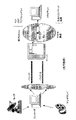
この発明の好ましい実施例を形成している二つの基本要素が図3に示されている。ここでサーバ40が提供されているのを見ることができ、ここには第一のビデオバッファ42と第二のビデオバッファ43とが備えられている。第一のビデオバッファ42はエンコードされたビデオデータを記憶するように構成されていて、このビデオデータは第一のビデオエンコード用レートで符号化されており、また第二のビデオバッファ43は第二のエンコード用レート(このレートは第一のバッファ42内に記憶されたエンコードされたビデオデータのレートより低い)でエンコードされた、第一のものよりも多いエンコードされたデータを記憶するように構成されている。二つのバッファ42,43内に記憶されたエンコードされたビデオデータは同じオリジナルデータから得られたものであるが、異なるエンコードされたビデオデータを与えるために異なるエンコード用レートを用いて符号化されたにすぎないことを理解されたい。一般に、第一のバッファ42内に記憶された符号化されたビデオデータを生成するために使用される高い方のエンコード用レートが原因となって、第一のバッファ42内のエンコードされたビデオデータは、第二のビデオバッファ43内に記憶された低い方のエンコード用レートでエンコードされた対応するエンコードされたビデオデータよりも大きなサイズをもっている。好ましいのは、ビデオデータはH.623エンコーデングを用いて符号化されているが、いずれもの適したビデオ符号化技術も使用できるのであって、その中にはMPEGなどがあることを理解されたい。
Two basic elements forming the preferred embodiment of the invention are shown in FIG. Here, it can be seen that the
またサーバ40の中に用意されているものに、オーディオデータバッファ44があり、これがエンコードされたオーディオデータを記憶するために用意されている。気付いてほしいのは、好ましい実施例では、オーディオデータは単一のエンコード用レートで符号化されるだけであり、したがって、単一のオーディオバッファだけが求められる。好ましいオーディオデータはAMRオーディオエンコーデングを用いて符号化されるが、MP3などのような他のいずれかの適当なオーディオ符号化技術も使用できる。
Also provided in the
サーバ40だけでなく、この好ましい実施例では、クライアント計算機50も用意されていて、ビデオバッファ52とオーディオバッファ54とを備えている。ビデオバッファ52はサーバ40から受領したエンコードされたビデオデータを受領して記憶するように構成されている。ビデオバッファ52は受領したエンコードされたビデオデータを記憶するが、これはクライアント計算機内に用意されたビデオデコーダがエンコードされたビデオデータをそこから読取って、そこでエンコードされたビデオ信号のデコードと再生にあてるまで記憶する。同じように、オーディオバッファ54はサーバ40から送られた、エンコードされたオーディオデータを受領して、このエンコードされたオーディオデータを、クライアント計算機内に用意されたオーディオデコーダがエンコードされたデータを読取ってエンコードされたオーディオ信号のデコードと再生にあてるまでバッファする。
In this preferred embodiment, not only the
サーバ計算機とクライアント計算機との間でデータ通信を提供するために、第一のユーザデータグラムプロトコル(UDP)接続10がサーバ40とクライアント50との間に提供されて、この接続を介してエンコードされたビデオデータがサーバ40から送られる。同じように、第二のUDP接続20もまたサーバ40から各クライアント50に向けて提供されて、この接続を介してエンコードされたオーディオデータが送られる。それぞれのUDP接続10,20の伝送レートは後述される方法でサーバによって制御される。
In order to provide data communication between the server computer and the client computer, a first user datagram protocol (UDP)
サーバとクライアントとの間のUDP接続に加えて、好ましい実施例ではトランスポート制御プロトコル(TCP)接続30がクライアントとサーバとの間に設定されて、制御メッセージの伝送を与えるようにしている。この制御メッセージは主としてクライアントからサーバーに向けて戻されるもので、二つのUDP接続10と20の伝送レートの実効的な制御ができるようにする。帰還データで各クライアントから、TCP接続上でサーバに向けて送られるものの詳細については後述する。
In addition to the UDP connection between the server and client, in the preferred embodiment, a Transport Control Protocol (TCP)
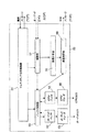
ここで図4を見ると、図4はサーバ計算機40内部でこの発明の好ましい実施例で必要とされる要素をブロック図形式で示している。図4はこの発明の動作に必要とされているサーバの部品だけを示していること、また動作に必要とされるサーバシステムの他の要素は示していないことに留意されたい。ここでは、意図された読者は当業者であって、サーバシステムについてのそれが全操作を実行するのに必要としている追加の要素が何であるかを認識する者であるとしている。
Turning now to FIG. 4, FIG. 4 illustrates in block diagram form the elements required by the preferred embodiment of the present invention within the
好ましい実施例では、サーバ計算機40は、マルチメディア応用(application)制御器41を備え、これがエンコードされたオーディオデータとエンコードされたビデオデータとを受領し、そこで受けたデータをバッファ42,43,44内にバッファように、図3に関して前記したように構成されている。留意してほしいのは、こういったバッファは明りょう化のために図4では示されていないことである。マルチメディア応用制御器41は制御メッセージをTCP接続30を介してクライアント計算機50との間で送受する。さらに、マルチメディア応用制御器はエンコードされたビデオデータとエンコードされたオーディオデータとを適当なバッファから網接続モジュール47に向けて提供し、モジュール47は網をまたいでクライアント計算機に向けた伝送のためにデータをパケット化する。したがって、網接続モジュール47はエンコードされたオーディオとビデオデータとをマルチメディア応用制御器から受領するように動作し、このデータを伝送に適した形態にパケット化して、このデータパケットを二つのそれぞれのUDPデータストリーム内で、適切とされるそれぞれの送りレートで網に向けて送る。データストリームのそれぞれの送り用レートは送り用レート計算器46により後述の適当な伝送レート式により計算される。送り用レート計算器46はオーディオとビデオのデータストリームについての計算された送りレートを網接続モジュール47に向けて送り、網接続モジュール47に計算された伝送レートについて通知するようにしている。好ましい実施例では、送り用レート計算器46で計算された伝送レート式に向けた入力データはクライアント計算機からマルチメディア応用制御器に向けたTCP接続上で得られていて、この制御器から網接続を経由して送り用レート計算器に向けてデータが送られる。
In the preferred embodiment, the
網制御器モジュール48はさらに、網接続47を制御するために用意されていてオーディオとビデオとのデータが網上で送られるようにするために適切なデータのパケット化プロセスを実行する。
The
さらに、再伝送バッファ49はメモリなどであり、これが与えられていて、網接続47から適切な制御信号と一緒にデータパケットを受領し、受領したデータパケットをバッファして、このバッファしたパケットを網接続47が再送しなければならない事象に備えるように構成されている。送られたデータパケットのバッファ動作と再送動作とはこの発明にとって特有のものではないのでこれ以上の詳細についてはここではふれない。
Further, the
図4に示されてはいないが、さらに次のことについては留意されたい。サーバ計算機40はさらに少くとも一つの計算機読取り可能記憶媒体を含んでいて、これが計算機プログラムを記憶し、このプログラムがこの発明を実施するためにサーバ計算機の動作を制御する。計算機読取り可能記憶媒体は既知のいずれの形式のものでもよく、とくに、光ディスク、磁気ディスク、磁気・光ディスク、固体計算機メモリ、あるいは他の適当なデータ記憶媒体のうちの一つまたは何らかの組合せから形式されるものでよい。
Although not shown in FIG. 4, further attention should be paid to the following. The
図5はこの発明の好ましい実施形態で必要とされるクライアント計算機50の機能素子のブロック図を示す。サーバ計算機40と同じように、図5は動作上クライアント計算機50にとって必要とされる部品のすべてを示しておらず、この発明の好ましい実施例の動作にとって必要とされる機能ブロック素子だけが示されていると理解されたい。読者として意図されているのは当業者であって、全動作に必要とされる他のクライアント計算機部品はどれかは理解できる者としている。
FIG. 5 shows a block diagram of functional elements of the
クライアント計算機50内部では、マルチメディア応用制御器51が用意されていて、この制御器はサーバ内で用意されたマルチメディア応用制御器41と対応している。マルチメディア応用制御器51は、クライアント計算機50内で実行しているマルチメディアアプリケーション(application)の高いレベル制御を提供し、またサーバ内の対応しているマルチメディア応用制御器41と、TCP接続30上で送られる制御メッセージを介して通信する。同じように、マルチメディア応用制御器51は制御信号をクライアント計算機50の他の機能素子に提供し、このクライアント計算機は好ましい実施例を構成するものとなっている。
In the
さらにクライアント計算機50内に用意されているのが網接続モジュール57であって、これは網からのデータパケットをいくつかのデータストリームの中で受領するように構成されている。いくつかのデータストリームの中で受領したデータに関する制御情報は測度計算器56に送られて、受領したデータストリームのある種の特性を示す定量的な値の計算にあたり、計算された定量的な値は帰還(feedback)送信機58に送られて、TCP接続30上で制御メッセージとして網を通って送り戻すのにあてられる。定量的な値の計算についてのさらなる情報は後に与えられる。
Further provided in the
網接続57はオーディオとビデオとのデータストリームを受領して、各ストリーム内のパケットからエンコードされたオーディオとビデオとのデータを読取る。エンコードされたオーディオとビデオとのデータは次にバッファ制御器59に送られて、制御器は受領したエンコードされたオーディオデータをオーディオバッファ54に供給し、また受領したエンコードされたビデオデータをビデオバッファ52に供給する。バッファ制御器59はさらにオーディオバッファ54とビデオバッファ52の状態を監視して、各バッファがどのくらい一杯であるかを判断し、また、各バッファが空となるレート(これはそこに記憶されたデータのデコード用レートを示している)を判断するように構成されている。オーディオデコーダ53はさらに用意がされていて、オーディオバッファ54からエンコードされたオーディオデータを読取り、かつエンコードされたオーディオデータをデコードして、デコードされたオーディオデータを出力として提供する。同じように、ビデオデコーダ55が用意されて、これがビデオバッファ52からエンコードされたビデオデータを取得し、エンコードされたビデオデータをデコードしてビデオ出力信号を提供する。
The
バッファ制御器59は、オーディオとビデオとのバッファの状態に関する情報を受領すると、この情報を帰還送信機に向けて送り、TCP接続30上でサーバ計算機に送り戻された制御メッセージの中に組入れるようにする。
When the
図5には示されていないが、クライアント計算機はさらに少くとも一つの計算機読取り可能記憶媒体を含んでいて、そこには計算機プログラムを記憶し、このプログラムはクライアント計算機がこの発明を実行する動作を制御することに注目すべきである。計算機読取り可能記憶媒体は既知の形式のいずれであってもよく、とくに光ディスク、磁気ディスク、磁気・光ディスク、固体計算機メモリ、あるいはいずれか他の適切なデータ記憶媒体のいずれか一つもしくは組合せの形式とすることができる。 Although not shown in FIG. 5, the client computer further includes at least one computer-readable storage medium that stores a computer program that operates to cause the client computer to perform the invention. It should be noted that control. The computer readable storage medium may be in any of the known formats, in particular in the form of any one or combination of optical disks, magnetic disks, magnetic / optical disks, solid state computer memories, or any other suitable data storage medium. It can be.
この発明のサーバ装置とクライアント計算機装置を形成している基本的な機能ブロックを記述したので、今度は本発明の好ましい実施例の動作の記述をこれから記載して行く。 Having described the basic functional blocks forming the server device and client computer device of the present invention, the description of the operation of the preferred embodiment of the present invention will now be described.
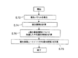
図6はこの発明の好ましい実施例によりサーバ計算機40により実行される段階の流れ図である。第一に、段階2では、送り用レート計算器46はサーバ計算機40から送られることになる個々のデータストリームのすべてにとって利用可能な全帯域幅を計算する。この値total_rateは伝送レート上の上限を表わしていて、この上限を各別個のデータストリームの個々の伝送レートはお互い合計されたときに越えてはならない。この値total_rateは次の原理により計算される。
FIG. 6 is a flowchart of the steps performed by the
一般に、以前のマルチメディアコンファレンス適用であって、現在インターネットで使用されているものは、UDPトランスポートプロトコルに基づいていて、このプロトコルは、以前に論じたように、サービスの品質制御機構を何も提供しておらず、それ故に、例えば網輻輳を補償するのに必要であるような制御動作を実行する能力はない。したがって、網輻輳が発生するときに、競合しているTCP接続は、UDPトラヒックに代っていずれかのレート低減なしに前述したように伝送レートを減じる。 In general, previous multimedia conference applications that are currently used on the Internet are based on the UDP transport protocol, which, as previously discussed, does not implement any quality control mechanisms for services. Does not provide, and therefore does not have the ability to perform control operations such as are necessary to compensate for network congestion, for example. Thus, when network congestion occurs, competing TCP connections reduce the transmission rate as described above without any rate reduction on behalf of UDP traffic.
この問題を回復させるために、この発明では、UDPオーディオとビデオとのデータストリームは輻輳制御方式で強化され、total_rateパラメータの計算は該方式の一部を形成している。とくに、パラメータtotal_rateは合計(total)の伝送レートを提供するために計算され、このレートは“TCPフレンドリィ”であって、伝送レートとなっていて、この伝送レートは時間にわたりTCP接続を介して達成されたスループットと類推できるものとなっている。 In order to remedy this problem, in the present invention, the UDP audio and video data stream is enhanced with a congestion control scheme, and the calculation of the total_rate parameter forms part of the scheme. In particular, the parameter total_rate is calculated to provide a total transmission rate, which is “TCP friendly” and is a transmission rate, which is achieved over time over a TCP connection. It can be inferred from the achieved throughput.
好ましい実施例では、全体の(total)伝送レートパラメータtotal_rateが伝送レート式を用いて計算され、この式はTCP接続の時間にわたる平均スループットをモデル化するように求められて、したがって、全体のレートはTCPフレンドリィな伝送レートを与えるように計算される。好ましい実施例では下記の式1で示した伝送レート式を使用している。
In the preferred embodiment, the total transmission rate parameter total_rate is calculated using a transmission rate equation, which is asked to model the average throughput over the time of the TCP connection, so the overall rate is Calculated to give a TCP friendly transmission rate. In the preferred embodiment, the transmission rate equation shown in
bit_rate_stream=c((packet_medium_size)/(RTT)√(loss_rate)) (式1)
上記のユビキタス(ubiquitous)TCP接続に適用される式の導入についてはFloyd,S.の“Connections with Multiple Congested Gateway in Packet Switched Networks Part1:One Way Traffic”,Computer Communications Review,vol.21,no.5,1991年10月, page30〜47に見出すことができることに留意されたい。
bit_rate_stream = c ((packet_medium_size) / (RTT) √ (loss_rate)) (Formula 1)
See Floyd, S.'s “Connections with Multiple Congested Gateway in Packet Switched Networks Part 1: One Way Traffic”, Computer Communications Review, vol. 21, no. 5 for the introduction of the above formula applied to ubiquitous TCP connections. , October 1991, pages 30-47.
上式ではcは定数であってその範囲は0.87ないし1.31であり、RTTはラウンドトリップ時間(単位秒)であって、これはあるパケットがある計算機からある網をまたいで他の計算機に行きまた戻る転送にかかる時間であり、loss_rateは受信機に至る際に失なわれたパケットの測定値であり、packet_medium_sizeは、計算が実行されている対象のストリーム内で伝送されるパケットの平均サイズである。式1のこれら要素についてのさらなる論議と、伝送レート式での使用のためにこれらがどのように計算されるかについては後に行なわれることに留意されたい。
式1はbit_rate_stream値を与え、この値は単一のTCP接続が現在の網状態で達成できる平均帯域幅の推定値である。しかしながら、好ましい実施例では、この推定値を直接にあるストリームについての全体の伝送レートとして使用せず、むしろこの値bit_rate_streamは次の式2に入れられる。
total_rate_stream=min(bit_rate_stream, 2* receiving_rate_stream) (式2)
パラメータreceiving_rate_streamはクライアント計算機からTCP接続上で受領され、クライアントによって特定のストリームについて受領されたビット数に対応していて、このストリームについては計算はRTT秒内に行なわれる。
In the above equation, c is a constant and its range is 0.87 to 1.31, and RTT is the round trip time (unit: second), which means that a packet is transmitted from one computer to another network The amount of time it takes to transfer to and from the calculator, loss_rate is a measure of the packet lost to reach the receiver, and packet_medium_size is the packet transmitted in the stream for which the calculation is being performed. Average size. Note that further discussion about these elements of
total_rate_stream = min (bit_rate_stream, 2 * receiving_rate_stream) (Formula 2)
The parameter receiving_rate_stream is received over the TCP connection from the client computer and corresponds to the number of bits received for the particular stream by the client, for which the calculation is done in RTT seconds.
上記の式2はTCPフレンドリィ性能を与えるために単一のUDPストリームについて利用可能な全体の帯域幅を与える。しかしながら、本実施例では、我々は複数のストリームの伝送に関心があり、このため上記計算は伝送されるべき各ストリームについて別個に実施されなければならない。即ち、式1と式2の両方が各ストリーム(即ち、本実施例ではオーディオとビデオのストリーム)に対して順番に適用されて、total_rate_stream値が各ストリームに関して見出される。こうして各ストリームに関して見出されたそれぞれの値が互いに合計されて、値total_rateを与えて、この値はTCPフレンドリィ性能を与えるためにすべてのストリームに利用可能な合計帯域幅であり、それによって可能な網輻輳を考慮する。
利用可能な最大伝送レートの計算に続いて、段階S4では、サーバにおける送りレート計算器46が個別の伝送レートを各データストリームについて計算する。このストリームは好ましい実施例ではオーディオUDPストリーム(audio_rate)の伝送レートとビデオUDPストリーム(video_rate)の伝送レートである。audio_rateとvideo_rateの値は以下のように計算される。
Following the calculation of the maximum available transmission rate, in step S4, the
図3に関して前述したように、オーディオデータはビデオデータから分離されてUDPストリーム内で送られ、ビデオデータは別のUDPストリーム内で送られ、それ故に二つの別個のUDP接続が存在し、各ストリームについて一つの接続となる。各ストリームは同じ網帯域幅について競合していると考えることができるけれども、実際にはこれは真実でなく、その理由は同一瞬間にビデオとオーディオとのデータパケットを送ることが可能でないことにある。したがって、二つのデータストリームがオーディオとビデオのストリームである場合には、前に計算した全体の送り用ビットレートはオーディオ送り用ビットレートにビデオ送り用ビットレートを加えたものと等価とすることができる。さらに、後で記述することになるように、好ましい実施例では、サーバがクライアントからビデオとオーディオのバッファの状態について情報を受領しており、またビデオとオーディオのパケットについてのデコード用レートについての情報を受領している。したがって、クライアント内のバッファの充填レートを制御するためにオーディオとビデオのデータストリームの送り用レートを制御することが可能となる。これは次のようにして達成される。 As described above with respect to FIG. 3, the audio data is separated from the video data and sent in a UDP stream, and the video data is sent in another UDP stream, so there are two separate UDP connections, each stream Will be one connection. Although each stream can be considered competing for the same network bandwidth, in practice this is not true, because it is not possible to send video and audio data packets at the same moment . Therefore, if the two data streams are an audio and video stream, the total sending bit rate calculated previously may be equivalent to the audio sending bit rate plus the video sending bit rate. it can. Further, as will be described later, in the preferred embodiment, the server receives information from the client about the status of the video and audio buffers, and information about the decoding rate for the video and audio packets. Has been received. Thus, it is possible to control the rate for sending audio and video data streams to control the buffer filling rate in the client. This is accomplished as follows.
先ず、filling_rate_audioとfilling_rate_videoの二つのパラメータを定義する。これらはそれぞれ受信機内でのオーディオとビデオのバッファのそれぞれがデータを充填しているレートである。この実施例では式3と式4とで与えられる。 First, two parameters, filling_rate_audio and filling_rate_video, are defined. These are the rates at which the audio and video buffers, respectively, in the receiver are filled with data. In this embodiment, equations 3 and 4 are given.
filling_rate_audio=audio_rate−decoding_audio_rate (式3)
filling_rate_video=video_rate−decoding_video_rate (式4)
受信機でのバッファの制御はバッファが比x:yで充填するように要求されていると仮定すると、そのときは
x(filling_rate_audio)=y(filling_rate_video) (式5)
であり、また
total_rate=audio_rate+video_rate (式6)
である。
filling_rate_audio = audio_rate-decoding_audio_rate (Formula 3)
filling_rate_video = video_rate−decoding_video_rate (Formula 4)
Assuming that control of the buffer at the receiver is required to fill with a ratio x: y, then
x (filling_rate_audio) = y (filling_rate_video) (Formula 5)
And also
total_rate = audio_rate + video_rate (Formula 6)
It is.
適当な代入を実行し、audio_rateとvideo_rateをそれぞれを解くことにより式7と式8とが与えられる:
audio_rate=[y(total_rate-decoding_video_rate)
+x(decoding_audio_rate)]/(x+y) (式7)
video_rate=[x(total_rate-decoding_audio_rate)
+y(decoding_video_rate)]/(x+y) (式8)
したがって、上記から明らかなように、それぞれのオーディオ送り用レートとビデオ送り用レートを制御して、受信機内でのそれぞれのオーディオとビデオのデコードレートに依存して一方のストリームから他方のストリームにビットレートを交換するようにすることが可能となる。さらに、上のことから注意すべきことは、パラメータtotal_rateは式1と2とを適用することから前に計算された値であってデータストリームのすべての伝送のために利用可能な全体の利用可能帯域幅、すなわち、total_rate=total_rate_stream_1+total_rate_stream_2+…+total_rate_stream_n(ここでnは同時に送られるデータストリームの数である)を与えるものであることである。
Performing the appropriate substitutions and solving audio_rate and video_rate respectively gives Equation 7 and Equation 8:
audio_rate = [y (total_rate-decoding_video_rate)
+ X (decoding_audio_rate)] / (x + y) (Formula 7)
video_rate = [x (total_rate-decoding_audio_rate)
+ Y (decoding_video_rate)] / (x + y) (Formula 8)
Therefore, as is apparent from the above, each audio sending rate and video sending rate is controlled and bit from one stream to the other depends on the respective audio and video decoding rate in the receiver. It becomes possible to exchange rates. Furthermore, it should be noted from the above that the parameter total_rate is the value previously calculated from applying
図6に戻ると、各ストリームについてオーディオとビデオの送りレートを計算した後で、段階S6では、サーバにおける網接続47はオーディオとビデオのストリームを分離されたUDPデータストリームとして、計算されたオーディオとビデオの送りレートで送る。このオーディオとビデオのストリームは連続して送られるので、図6の段階は、継続的に示しているものの、実際には並列に実行されて、オーディオとビデオのストリームの伝送レートは現実にはオーディオとビデオの伝送レートについて新しい値が計算されると更新される。しかしながら、この新しい計算が実行されている間には、これらのストリームは以前に計算したレートで送られ続けることになっている。
Returning to FIG. 6, after calculating the audio and video feed rates for each stream, in step S6, the
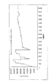
図11は図2にプロットされたTCP接続により送られたのと同じデータを送っているときにこの発明の好ましい実施例により制御される一つのデータストリームについての測定された伝送レートのプロットを示し、図11からは、このセッションの開始時に経験した初期の過渡的な変化の後に、ストリームの伝送レートは安定となって、時間に対して比較的僅かな変動で連続することがわかる。さらに、図2に示したTCP接続により経験された伝送レートと比較するときは、殆んど同一の平均スループットがTCPのように達成されるが、TCPの乗算式の減少制御アルゴリズムからの結果である伝送レートに大きな変化を伴うことがないことが分かる。この時間に関して滑らかな伝送レートを与えるという性質は、この発明を連続するストリーミングを求めるデータを送るときでの使用にとくに適切なものとなっている。 FIG. 11 shows a plot of measured transmission rates for one data stream controlled by the preferred embodiment of the present invention when sending the same data sent by the TCP connection plotted in FIG. From FIG. 11, it can be seen that after the initial transient change experienced at the beginning of this session, the transmission rate of the stream becomes stable and continues with relatively little variation over time. Furthermore, when compared to the transmission rate experienced by the TCP connection shown in FIG. 2, almost the same average throughput is achieved as in TCP, but with the results from the TCP multiplying reduction control algorithm. It can be seen that there is no significant change in a certain transmission rate. The property of providing a smooth transmission rate with respect to this time makes the present invention particularly suitable for use in sending data for continuous streaming.
図6の段階S8では、サーバ計算機40は帰還データをクライアント計算機50から受領する。好ましい実施例ではこのデータは段階S2と段階S4の全体の伝送レートとデータストリーム伝送レートの計算を実行するために必要とするものである。とくに各ストリームについて、サーバはクライアントにおいて現在経験しているラウンドトリップ時間と、クライアントでのパケットの損失レートと、クライアントにおけるオーディオとビデオのバッファのそれぞれのデコード用レートと、クライアントにおける各データのデータストリームのデータ受信レートとについて知らせるデータをサーバが受領する。こういった定量的な値はサーバに向けてTCP接続を経由して各クライアントから送り戻される。
In step S8 of FIG. 6, the
いったん更新された帰還データがクライアントから受領されたならば、これがサーバ内の送り用レート計算器46に送られて、ここで段階S2とS4での計算をもう一度行ない、その結果が網接続47に向けて送られる。この網接続はオーディオとビデオのストリームを新しい計算された送り用レートで送る。このプロセスはクライアントのセッションの間に連続している。
Once the updated feedback data has been received from the client, it is sent to the sending
定量的な値であってクライアント計算機からサーバに向けて送り戻されたものについての計算を、図7において展開されたようにクライアント計算機の動作に関して論述することとする。図7を参照すると段階S1ではクライアント計算機50内での網接続57は別々のオーディオとビデオのデータストリームを、網上での個々のUDP伝送として受領する。前述のように、網接続57はそれぞれのUDPストリームからのエンコードされたオーディオとビデオのデータのパケット化を解いて(depacketises)、このエンコードされたオーディオとビデオのデータをバッファ制御器59に向けて送り、バッファ化と後のデコード化とにあてる。
The calculation of the quantitative value sent back from the client computer to the server will be discussed with respect to the operation of the client computer as developed in FIG. Referring to FIG. 7, in step S1, the
バッファ制御器59によって受領されたエンコードされたオーディオとビデオのデータはそれぞれオーディオバッファ54とビデオバッファ52に記憶される。段階S3では、バッファ制御器59はオーディオバッファ54とビデオバッファ52とにそれぞれ問合せをして各バッファの状態を判断するようにする。とくに、バッファ制御器は各バッファはどのくらい充填されているかと、どのくらい速くにエンコードされたオーディオとビデオの情報であって各バッファ内にあるものがそれぞれのオーディオとビデオのデコーダ53,55によってデコードされているかについての情報を判断する。これがどのくらい速くオーディオとビデオのバッファがそれぞれのデコーダによって空にされているかを示すものとなっている。バッファ制御器がオーディオとビデオのバッファの状態を判断すると、判断された情報が帰還送信機58に送られて、制御メッセージの中に閉じ込められ(encapsulation)、サーバ計算機40への戻り伝送にあてられる。
The encoded audio and video data received by the
エンコードしたオーディオとビデオデータをバッファ制御器に向けて送ることに加えて、網接続57はまた受領したデータに関する情報を測度計算器56に向け送り、測度計算器56が帰還送信機58によりサーバに向けて送り戻された定量的な測度値を計算できるようにする。したがって、段階S5,S7,及びS9では、測度計算器がそれぞれ各ストリームについてラウンドトリップ時間(RTT)と、損失事象のレートと、ストリーム当りの受領したデータレートとを計算し、これらの計算値はすべてサーバにおいて式1と2との入力として必要とされているものであり、データストリームについて利用可能な伝送レートの計算にあてられる。三つの測度が各受領したデータストリームについて個々に計算され、一組の測度が各受領したデータストリームについて与えられるようになっていることに留意されたい。こういった定量的の値の各々についての計算は次に論じられる。
In addition to sending the encoded audio and video data to the buffer controller, the
RTTに関しては、前述の通り、RTTがパケットがある計算器から網をまたいで他の計算機に行って戻って来る移動にかかる時間の測定値である。RTTはそれ故にクライアント計算機において測度計算器56内部で測定された何かであるが、発振(oscillations)防止のために次式で計算されるのが好ましい。
Regarding RTT, as described above, RTT is a measured value of the time taken for a packet to return from a computer with a packet across the network to another computer. The RTT is therefore something measured inside the
RTT=0.2* RTTsample+0.8* RTTmean (式9)
値RTTsampleは測度計算器によって測定されたRTTの最新の測定値であり、また値RTTmeanは以前のRTTの全測定値の平均値である。
RTT = 0.2 * RTT sample + 0.8 * RTT mean (Formula 9)
The value RTT sample is the latest measured value of the RTT measured by the measure calculator, and the value RTT mean is the average value of all previous measured values of the RTT.
段階S7では、測度計算器56はクライアント計算機で経験したストリーム当りの損失事象レートを計算する。損失事象レートの計算は最も複雑な計算であり、この計算は速度計算器56が実行しなければならないものであり、また到着するパケットの一連番号からUDPストリーム内の失なわれたパケットの検出に依存している。この失なわれたパケットの検出は到着するパケット内のパケット一連番号の検出に基づいて網接続により実行され、ここでは予期されたパケットが失なわれたと定義されるが、その条件は少くとも三つのパケットであって予期されたパケットよりも大きな一連番号をもつものが、予期されたパケットが到着していない状態で、受信機に到達するものである。したがって、もし一連番号5をもつパケットが予期されているとすると、そのときは到達する次のパケットがパケット6,パケット7,そしてパケット5である場合には、このときはパケット5は損失されたと定義されない。しかし次の3つのパケットで順に到着するものがパケット7,8,そして6であると、そのときは到着したパケットの三つ各々が予期されたパケット番号5よりも大きなシーケンス番号であるから、パケット5は損失と定義される。
In step S7, the
上記のようにパケットが損失としてどのように定義されるかを特定した上で、測度計算器は損失事象(loss event)として知られる別の出現(occurrence)を定義する。好ましい実施例では、損失事象はいずれかのRTT測定においていくつかのパケットの損失の検出として定義されている。したがって、もしいずれかの特定のRTT測定で、パケットでその番号が4,6,7,9,10、11のものが到着したとすると、そのときは、パケット5と8とは失なわれているけれども、特定の測定されたRTTでは実際には一つだけの損失事象であったとされる。この方法は網内で同時に失なわれている複数のパケットについても説明されるところであり、全体の損失事象のレート計算に過度に影響を与えるものではない。
Having specified how a packet is defined as lost as described above, the measure calculator defines another occurrence, known as a loss event. In the preferred embodiment, a loss event is defined as the detection of the loss of several packets in any RTT measurement. Thus, if any particular RTT measurement arrives with a packet whose number is 4, 6, 7, 9, 10, or 11, then
上述のように損失事象がいったん検出されると、ステップS74において測度計算器56は最近の損失間隔(loss interval)を計算する。これは現在検出された損失事象と以前に検出された損失事象との間で受領されたパケットの数である。測度計算器は新しく計算された損失間隔を、n個の最近計算した損失間隔と一緒に記憶して、平均損失間隔値を与えるために加重したフィルタでの応用にあてる。平均損失間隔値は次のように計算される。
Once a loss event has been detected as described above,
図9と10とを参照すると、図10は測度計算器を作り上げている若干の機能素子を示しており、これらの素子が損失レートの計算のために使用されている。とくに、損失事象検出器562は前述したように損失事象を検出して、最新計算された損失間隔を多数の直列接続された(serially-connected)損失間隔バッファ564の第一のものに向けて出力する。新しい損失間隔が第一のシリーズバッファ564に入力されるときは、前の損失間隔値として第一のバッファ内に保存されているものが次のバッファへとシフトされ、ここで言う次のバッファの値はシリーズ内の次のバッファというように順にシフトされることが図10に示されている。この方法では、n個の最新の損失間隔値は平均損失間隔値を計算するのに使用するために記憶される。シフトバッファ564内に記憶された各損失間隔値は、時間加重された損失間隔係数A0〜Anによりそれぞれ乗算される。この係数はそれぞれの係数メモリ656に記憶されている。係数の個々の値A0〜Anは図9に示したように、時間加重された係数関数に従って求められ、この関数は最近の損失間隔が平均損失間隔の計算に向けて前の計算から記憶された歴史的な損失間隔よりも大きな拡がり(extent)までカウントすることを確かにする。この時間加重したフィルタを応用する目的は、計算された損失事象レートが滑かに変化することを確かにすることである。
Referring to FIGS. 9 and 10, FIG. 10 shows some functional elements that make up the measure calculator, and these elements are used for the loss rate calculation. In particular,
加重された損失間隔計算の結果は合算機器(summer)566で合算され、その結果はインバータ568に向けて送られて、損失レートの計算にあてられ、合算機器566により計算された平均損失間隔の逆数となる。こうして計算された損失レートはそこで帰還送信機58に送られて、前記のようにサーバ計算機に向けた伝送にあてられる。
The results of the weighted loss interval calculation are summed in a summing device (summer) 566 and the results are sent to
受領したデータレートの計算はまた測度計算器56によっても実行され、RTT秒内のデータストリーム内でクライアントにより受領されたビットの数の直截的な(straightforward)測定値となる。各ストリーム内のいずれかの一時刻で受領されるデータ量に関する情報は網接続57から測度計算器56に向けて送られて、ストリーム毎の受信レートの計算にあてられる。計算されたストリーム毎の受信レートはそこで帰還送信機58に向けて送られて、前述のようにサーバ計算器に向けて送り戻されるようにする。
The calculation of the received data rate is also performed by the
いったん帰還送信機58がバッファ制御器59と測度計算器56からの必要とされる情報を受領したときには、送信機はこの情報をTCP接続30内の網上での伝送に適した形式にパケット化する。
Once the
図7の流れ図に示された段階S1〜S13は例示だけの目的のものであり、またクライアント計算機50は事実所望されるどんな順序でもこれらの段階のいずれかあるいは全部を実行できる。さらに、これらの段階のいくつかを並列に実行することも可能であり、例えば、バッファ制御器59により実行されたオーディオとビデオとのバッファのチェックと測定とは測度計算器56によって実行される計算と並列に実行されることができる。しかしながら、好ましい実施例では、受信機にとっては、サーバ計算機に向けて送り戻される定量的な値を計算するのに必要な情報を持つために、オーディオとビデオとのデータストリーム内に実際に受領したデータを持つことが必要であることに留意されたい。
The steps S1-S13 shown in the flow diagram of FIG. 7 are for illustrative purposes only, and the
サーバ内部では、各ストリームの実際の伝送レートは網制御器48と網接続47との組合わせで制御されていて、計算されたレートに従って網上にパケットを実際にレリーズすることによって行なわれる。しかしながら、好ましい実施例で記述したオーディオとビデオデータの伝送をする特別な場合には、ビデオデータに関して、特に計算されたレートは使用された特定のエンコードレートについての伝送レート要求を満足しないことになることもあり得る。この場合に、ビデオストリームについての計算された伝送レートが低下して、現在のビデオエンコードレートで、ビデオストリーム内で十分なデータを送り、受信機にあるビデオバッファを空にすることを妨げることができないように思われれば、網制御器48は網接続47を制御して低レートエンコード用ビデオバッファ43からエンコードされたビデオデータを採り出すようにし、これが低品質でエンコードされていて、より低い計算された伝送レートで網をまたいだ伝送により適切なものとなっている。受信機では、低レートのエンコードされたビデオデータはビデオバッファ内に置かれていて、ビデオデコーダ55は低い方のレートのエンコードを検出して、自己のデコードレートをより低いレートに変えて、これがビデオデータをビデオバッファから読取るレートに低減する。このような測定値がビデオバッファを完全に空にすることを防いで、それによりクライアント計算機における連続したビデオ再生を可能ににしている。
Inside the server, the actual transmission rate of each stream is controlled by a combination of the
この発明の好ましい実施例はオーディオとビデオとのデータを複数のデータストリームとして送ることを指向しているので、好ましい実施例内部では、各ストリームのそれぞれのビットレートを設定するための規準はオーディオとビデオのデータの特別な要件を反映するように選定されていて、もとのオーディオとビデオとの信号を再生するために受信機でそのようにデコードされなければならないことに留意されたい。しかしながら、この発明は複数のデータストリームとしてのオーディオとビデオデータの伝送に限定されておらず、事実いくつかのストリームの中での送りが求められているいずれもの形式のデータがこの発明を用いて伝送される。さらに、これらのストリーム間でビットレートを交換するために選ばれた特定の規準がデータが置かれることになる応用に依存することになる。例えば、この発明の他の実施形態を想定することも可能であり、この場合にデータは複数のストリーム内で送られて、多数のセンサがマウントされている例えば遠方のビークル(vehicle)の遠隔制御に影響を与えるようにする。このようなビークルは、例えば海中の潜水可能な探査ビークルなどであってよく、そこには無線網接続が備えられている。このような場合には、データの複数のストリームが潜水艇の操縦素子へ操縦制御情報を与えることが必要とされ、また個々のセンサに向けてセンサ制御情報を与えることが必要とされてよい。このようなデータストリーム間でビットレートが交換されるようにする規準は、オーディオとビデオとのデータを伝送することに関係するこの発明の好ましい実施例で必要とされるものとは異なることになり、したがって、一方のデータストリームから他へのビットレートの交換を制御するために選ばれる規準は応用に依存することになるのは明らかである。 Since the preferred embodiment of the present invention is directed to sending audio and video data as multiple data streams, within the preferred embodiment, the criteria for setting the respective bit rate for each stream are audio and video. Note that it is chosen to reflect the special requirements of the video data and must be so decoded at the receiver to reproduce the original audio and video signals. However, the present invention is not limited to the transmission of audio and video data as multiple data streams, and in fact any form of data that is required to be sent in several streams can be used with the present invention. Is transmitted. Furthermore, the specific criteria chosen to exchange the bit rate between these streams will depend on the application in which the data is to be placed. For example, other embodiments of the invention can be envisaged, in which case data is sent in multiple streams, for example remote control of a distant vehicle in which multiple sensors are mounted. To affect. Such a vehicle may be, for example, a submersible exploration vehicle in the sea, which is equipped with a wireless network connection. In such cases, multiple streams of data may be required to provide steering control information to the submarine's steering element and may be required to provide sensor control information to individual sensors. The criteria for exchanging bit rates between such data streams will be different from those required in the preferred embodiment of the present invention relating to transmitting audio and video data. Thus, it is clear that the criteria chosen to control the exchange of bit rates from one data stream to the other will depend on the application.
さらに、この発明で使用される利用可能な全部の伝送帯域幅の計算に関しては、好ましい実施例では伝送レート式が使用されたが、この式は標準のTCP接続によって得られる平均のスループットをシミュレートすることが意図されている。しかしながら、この特定の式もまたこの式を使用する理由もこの発明での限定となることを意図したものでないことを理解されたい。また事実、いずれか適当な伝送レート式が利用可能な全体の伝送レートを計算するために使用できて、このレートは次に個々のストリーム伝送レートを計算するために使用されることを理解されたい。 In addition, for the calculation of the total available transmission bandwidth used in the present invention, a transmission rate equation was used in the preferred embodiment, which simulates the average throughput obtained by a standard TCP connection. Is intended to be. However, it should be understood that this particular formula and the reason for using this formula is not intended to be a limitation on the present invention. In fact, it should be understood that any suitable transmission rate equation can be used to calculate the total available transmission rate, which is then used to calculate the individual stream transmission rate. .
とくに、また例として、伝送がインターネットプロトコル網上で行なわれることになるところでは、TCPフレンドリィな伝送レートを与える他の伝送レート式がこの特殊な実施例で使用される式のかわりに使用できるのであって、各種の他のTCPフレンドリィな式が現在では当業者の知るところである。さらに、異なるパラメータ入力として必要とする異なる式が用いられるところではクライアント計算機はサーバによって必要とされているパラメータはどんなものでも計算して供給するように構成しなければならない。IP網が使用されない場合には、選ばれた伝送レート式は関心のある特定の網上で使用されているどんなトランスポートプロトコルに対しても有意なものとなっているべきであることが好ましいし、また網輻輳と結果として生ずるパケット損失などのような因子を計算に入れるために有意の伝送レート制御を提供することが好ましい。この発明の他の実施例では、どんな伝送レート式が適切であるかが、本発明の応用の特定分野に依存していて、それが当業者にとって明らかになる。 In particular and by way of example, where transmission is to take place over an Internet protocol network, other transmission rate equations that give TCP-friendly transmission rates can be used instead of the equations used in this particular embodiment. Thus, various other TCP-friendly expressions are now known to those skilled in the art. Furthermore, where different formulas are used that require different parameter inputs, the client computer must be configured to calculate and supply whatever parameters are needed by the server. If no IP network is used, the chosen transmission rate formula should preferably be significant for any transport protocol used on the particular network of interest. It is also desirable to provide significant transmission rate control to account for factors such as network congestion and resulting packet loss. In other embodiments of the invention, what transmission rate equation is appropriate depends on the particular field of application of the invention and will be apparent to those skilled in the art.
TCPスループットをシミュレートするために使用することができる別の伝送レート式の例であって、上述したような別の式の例を次に記述する。 An example of another transmission rate equation that can be used to simulate TCP throughput, as described above, will now be described.
スループット方程式で下記のものはRenoTCP用のスループット方程式の僅かに簡単化したものである。この発明では式1に代って使用されることができてストリーム当りの伝送レートの計算することができる。このスループット式は、
X=s/[R*sqrt(2*b*p/3)+(t_RTO*(3*sqrt(3*b*p/8)*p*(1+32*p^2)))]
(式10)
ここでXは伝送レート(バイト/秒単位),
sはバケットのサイズ(バイト単位),
Rはラウンドトリップ時間(秒単位),
pは損失事象レートであり、0と1.0の間。送られたパケット数の一分としてパケット損失事象の数についての割合となっている,
t_RTOはTCP再伝送時間切れ値(秒単位),
bは単一のTCPアクノレッジにより受領告知されたパケットの数である。
The throughput equation below is a slightly simplified version of the throughput equation for RenoTCP. In the present invention, it can be used in place of
X = s / [R * sqrt (2 * b * p / 3) + (t_RTO * (3 * sqrt (3 * b * p / 8) * p * (1 + 32 * p ^ 2)))]
(Formula 10)
Where X is the transmission rate (in bytes / second),
s is the size of the bucket (in bytes),
R is the round trip time (in seconds),
p is the loss event rate, between 0 and 1.0. It is a percentage of the number of packet loss events as a fraction of the number of packets sent,
t_RTO is the TCP retransmission timeout value (in seconds),
b is the number of packets acknowledged by a single TCP acknowledgement.
ラウンドトリップ時間と損失事象レートであって上記で使用されるものは前述のように計算される。さらにこの評価をさらに簡単化することができ、そのためにはt_RTO=4* R と設定する。もっと正確なt_RTOの計算が可能であるが、現在の設定での実験は既存のTCP実施で妥当な公平さをもたらしている。別の可能性はt_RTO=max(4R,1秒)に設定されて、RTOに1秒という推奨される最小値を整合させるものである。 The round trip time and loss event rate used above are calculated as described above. This evaluation can be further simplified by setting t_RTO = 4 * R. Although a more accurate t_RTO calculation is possible, experiments with the current settings have provided reasonable fairness with existing TCP implementations. Another possibility is to set t_RTO = max (4R, 1 second) to match the recommended minimum value of 1 second to RTO.
この発明の実施例で上記の方程式を前述のように使用するものでは、上記式10は単に先に記述した実施例での式1に代入される。他の処理段階は実質的に同じもののままである。
In the embodiment of the present invention where the above equation is used as described above,
Claims (29)
伝送レート式を用いてデータの伝送用の全体の伝送レートを計算する段階と、
受信機に向けて少くとも二つの別個のデータストリームを各々がそれぞれのデータ伝送ビットレートで伝送するために網上でデータを送り、該受信機からフィードバックデータを受領する段階と、
該受領したフィードバックデータに応答して、該それぞれのデータストリームの二つの少くともサブセットのそれぞれのデータ伝送レートを制御して、前記ストリーム間で所定のデータ伝送レートを維持するために、該ストリーム間でビットレートを交換する段階とを備え、
各データストリームのそれぞれの伝送レートの和は、実質的に該計算された全体の伝送レート以下であり、
前記データの伝送用の全体の伝送レートを計算する段階は、前記データの伝送前に送信側で実行される、方法。A method of data transmission across a network from a transmission side to a reception side, the method comprising:
Calculating an overall transmission rate for transmission of data using a transmission rate equation;
At least towards the receiver Ri send data over the network to each of the two separate data streams are transmitted in respective data transmission bit rate, the method comprising: receiving feedback data from the receiver,
In response to the received feedback data, between the streams to control a data transmission rate of each of the two at least subsets of the respective data streams to maintain a predetermined data transmission rate between the streams. And exchanging the bit rate at
The sum of the respective transmission rates of each data stream is substantially less than or equal to the calculated overall transmission rate;
The method of calculating an overall transmission rate for the transmission of data is performed at a transmission side before transmission of the data.
sr_str_1=[y(tr-dr_str2)+x(dr_str1)]/(x+y)
sr_str_2=[x(tr-dr_str1)+y(dr_str2)]/(x+y)
ここで変数は次の関係があるものとする;
sr_str_1:第一のデータストリームの送りレート
sr_str_2:第二のデータストリームの送りレート
tr:計算された全体の伝送レート
dr_str1:第一のデータストリーム内のデータの受信機におけるデコード用レート
dr_str2:第二のデータストリーム内のデータの受信機におけるデコード用レート
x:第一のデータストリームからデータを受領する受信機の第一のバッファの充填用レートの係数
y:第二のデータストリームからデータを受領する受信機の第二のバッファの充填用レートの係数。The method of claim 3, wherein, in the case of the two data streams, the method in which each data transmission rate is controlled by the following equation:
sr_str_1 = [y (tr-dr_str2) + x (dr_str1)] / (x + y)
sr_str_2 = [x (tr-dr_str1) + y (dr_str2)] / (x + y)
Where the variables have the following relationship:
sr_str_1: First data stream feed rate
sr_str_2: Second data stream feed rate
tr: Calculated overall transmission rate
dr_str1: Decoding rate at the receiver of data in the first data stream
dr_str2: Decoding rate at the receiver of data in the second data stream x: Coefficient of the filling rate of the first buffer of the receiver that receives data from the first data stream y: From the second data stream The rate factor for filling the second buffer of the receiver that receives the data.
ラウンドトリップ時間値(RTT)と、損失レート値と、並びに/または該受信機における受信レート値のいくつかを示している該受信機からの帰還データを受領する段階と、
該全体の伝送レートを該帰還データによって示されたいくつかの受領した値の関数として計算する段階とを備え、
該ラウンドトリップ時間は送信機から該受信機に向いかつ該送信機に戻る移動をするためにデータが要する時間の測度であり、該損失レート値は該受信機に向けて送られた失なわれたデータの量の測度であり、また該受信レート値はラウンドトリップ時間内に受領されたビットの数である、方法。The method according to any one of claims 1 to 5 , wherein the calculating step further comprises:
Receiving feedback data from the receiver indicating a round trip time value (RTT), a loss rate value, and / or some of the reception rate values at the receiver;
Calculating the overall transmission rate as a function of several received values indicated by the feedback data;
The round trip time is a measure of the time required for data to travel from the transmitter to the receiver and back to the transmitter, and the loss rate value is the loss rate sent to the receiver. It was a measure of the amount of data and the received rate value is the number of bits received within a round trip time method.
bit_rate_per_stream_x=c((data_medium_size)/(tRTT√(lossrate)))
ここで:
total_rate_stream_x=min(bit_rate_per_stream_x, 2×Receiving_Rate_x)であり、
また、total_rate=total_rate_stream_1+total_rate_stream_2+…+total_rate_stream_nであり、
ここでx∈{1,2,…,n}であり、data_medium_sizeは網をまたいで送られるストリーム当りのデータの平均サイズの測度であり、またcは定数であって0.87<c<1.31の範囲のものとし、nは送られることになるデータストリームの数である。The method of claim 6 , wherein the overall transmission rate is calculated by the following equation :
bit_rate_per_stream_x = c ((data_medium_size) / (t RTT √ (loss rate )))
here:
total_rate_stream_x = min (bit_rate_per_stream_x, 2 × Receiving_Rate_x)
Also, total_rate = total_rate_stream_1 + total_rate_stream_2 +… + total_rate_stream_n,
Where x∈ {1, 2,..., N}, data_medium_size is a measure of the average size of data per stream sent across the network, and c is a constant, 0.87 < c < 1 .31 range, where n is the number of data streams to be sent.
伝送レート式を用いてデータの伝送用の全体の伝送レートを計算するための伝送レート計算手段と、
データを網上で受信機に向けた伝送のために、少くとも二つの別個のデータストリーム内でそれぞれのデータ伝送ビットレートで送り、該受信機からフィードバックデータを受領するためのデータストリーム伝送手段と、
該受領したフィードバックデータに応答して、該それぞれのデータストリームの二つの少くともサブセットのそれぞれのデータ伝送レートを制御して、前記データストリーム間で所定のデータ伝送レートを維持するために、前記ストリーム間でビットレートを交換するためのデータストリーム制御手段とを備え、
該データストリーム制御手段はさらに、各データストリームのそれぞれの伝送レートの和が、計算された全体の伝送レート以下に実質的になるように制御されるよう動作可能であり、
前記伝送レート計算手段は、前記データの伝送前に送信側で前記全体の伝送レートを計算するように構成された、システム。A data transmission system across the network from the sending side to the receiving side,
A transmission rate calculating means for calculating an overall transmission rate for data transmission using a transmission rate equation;
The data for transmission towards the receiver on the network, at least Ri feed in each of the data transmission bit rate within the two separate data streams, the data stream transmission means for receiving feedback data from the receiver When,
In response to the received feedback data, the stream to control a data transmission rate of each of at least two subsets of the respective data stream to maintain a predetermined data transmission rate between the data streams. Data stream control means for exchanging bit rates between them,
The data stream control means is further operable to be controlled such that the sum of the respective transmission rates of each data stream is substantially less than or equal to the calculated overall transmission rate;
The transmission rate calculating means is configured to calculate the overall transmission rate on the transmission side before transmitting the data.
sr_str_1=[y(tr-dr_str2)+x(dr_str1)]/(x+y)
sr_str_2=[x(tr-dr_str1)+y(dr_str2)]/(x+y)
ここで変数は次の関係があるものとする;
sr_str_1:第一のデータストリームの送りレート
sr_str_2:第二のデータストリームの送りレート
tr:計算された全体の伝送レート
dr_str1:第一のデータストリーム内のデータの受信機におけるデコード用レート
dr_str2:第二のデータストリーム内のデータの受信機におけるデコード用レート
x:第一のデータストリームからデータを受領する受信機の第一のバッファの充填用レートの係数
y:第二のデータストリームからデータを受領する受信機の第二のバッファの充填用レートの係数。14. The system according to claim 13 , wherein in the case of two data streams, the respective transmission rates are controlled by the following equation :
sr_str_1 = [y (tr-dr_str2) + x (dr_str1)] / (x + y)
sr_str_2 = [x (tr-dr_str1) + y (dr_str2)] / (x + y)
Where the variables have the following relationship:
sr_str_1: First data stream feed rate
sr_str_2: Second data stream feed rate
tr: Calculated overall transmission rate
dr_str1: Decoding rate at the receiver of data in the first data stream
dr_str2: Decoding rate at the receiver of data in the second data stream x: Coefficient of the filling rate of the first buffer of the receiver that receives data from the first data stream y: From the second data stream The rate factor for filling the second buffer of the receiver that receives the data.
該ラウンドトリップ時間は、データが送信機から受信機へ向けてさらに送信機に向けて戻る移動にかかる時間の測度であり、該損失レート値は該受信機に向けて送られたデータの失なわれた量の測定であり、また該受信レート値は該ラウンドトリップ時間内に受領されたビット数である、システム。In the claims 11 to any one of the described system of claim 15, wherein the system further the round-trip time (RTT) value, the loss rate value, and / or the received indicating a number of reception rate values in said receiver Data receiving means for receiving feedback data from the machine, and the transmission rate calculating means further calculates the overall transmission rate as a function of some of the received values indicated by the feedback data. Composed,
The round trip time is a measure of the time it takes for data to travel from the transmitter back to the receiver and back towards the transmitter, and the loss rate value is the loss of data sent to the receiver. is a measure of the cracking amount, also the received rate value is the number of bits received in said round-trip time, the system.
bit_rate_per_stream_x=c((data_medium_size)/(tRTT√(lossrate)))
ここで:
total_rate_stream_x=min(bit_rate_per_stream_x, 2×Receiving_Rate_x)であり、また、total_rate=total_rate_stream_1+total_rate_stream_2+…+total_rate_stream_nであり、
ここでx∈{1,2,…,n}であり、data_medium_sizeは網をまたいで送られるデータ当りの平均サイズの測度であり、またcは定数であって0.87<c<1.31の範囲のものとし、nは送られることになるデータストリームの数である。In claim 16 of the system, the transmission rate of the該全body is calculated by the following equation system,
bit_rate_per_stream_x = c ((data_medium_size) / (t RTT √ (loss rate )))
here:
total_rate_stream_x = min (bit_rate_per_stream_x, 2 × Receiving_Rate_x), total_rate = total_rate_stream_1 + total_rate_stream_2 + ... + total_rate_stream_n,
Where xε {1, 2,..., N}, data_medium_size is a measure of the average size per data sent across the network, and c is a constant, 0.87 < c < 1.31. Where n is the number of data streams to be sent.
少くとも二つの別個のデータストリームの各々をそれぞれのデータ伝送レートで受領する段階と、
各ストリーム内の該受領したデータをそれぞれのデータバッファに向けてそこでバッファするために送る段階と、
該受領したデータのいくつかの特性を示すいくつかの定量的な値を計算する段階と、
該計算された定量的な値を送信機に向けて送り、そこから送られるデータ用の全体の伝送レートの計算での使用のための段階とを備える方法。The data sent by claim 1 or system according to any one of claims 11 to 19 or according to the method of transmission of any one of claims 10 A method of receiving from the network, the The method is
Receiving each of at least two separate data streams at a respective data transmission rate;
Sending the received data in each stream to the respective data buffer for buffering there;
Calculating several quantitative values indicative of some characteristics of the received data;
How and a stage for the the calculated quantitative value sent towards the transmitter, for use in calculating the total transmission rate for data sent therefrom.
該それぞれのデータデコード用レートは送信機に向けて該計算された定量的な値の少くとも一つとして送られる方法。The method of claim 21 , further comprising the step of decoding the data in each buffer at a respective decoding rate,
How the respective data decoding rate to be sent as one at least of the quantitative value that is the calculated toward the transmitter.
少くとも二つの別個のデータストリームの各々をそれぞれのデータ伝送レートで受領するためのデータ受領手段と、
それぞれの受領したデータストリームからその中にデータを受領するように構成された少くとも二つのデータバッファと、
該受領したデータのいくつかの特徴を示すいくつかの定量的な値を計算するための計算手段と、
該計算された定量的な値を送信機に向けて送り、そこから送られるデータについての全体の伝送レートを計算する使用にあてるデータ伝送手段とを備えるシステム。A system for receiving data from the network, the data is either by transmission method according to any one of claims 1 to 10, the transmission system according to any one of claims 11 to 19 And the system is
Data receiving means for receiving each of at least two separate data streams at a respective data transmission rate;
At least two data buffers configured to receive data therein from each received data stream;
Calculating means for calculating several quantitative values indicative of some characteristics of the received data;
System comprising a data transmission means for applying the use of feed toward the calculated quantitative value to the transmitter, calculates the total transmission rate for data sent therefrom.
Applications Claiming Priority (2)
| Application Number | Priority Date | Filing Date | Title |
|---|---|---|---|
| EP01308054A EP1296479A1 (en) | 2001-09-21 | 2001-09-21 | Data communication method and system for transmitting multiple data streams calculating available bandwidth per stream and bit stream trade-off |
| PCT/GB2002/004203 WO2003026233A1 (en) | 2001-09-21 | 2002-09-13 | Data communications method and system for transmitting multiple data streams calculating available bandwidth per stream and bit stream trade-off |
Publications (3)
| Publication Number | Publication Date |
|---|---|
| JP2005503723A JP2005503723A (en) | 2005-02-03 |
| JP2005503723A5 JP2005503723A5 (en) | 2006-01-05 |
| JP4263604B2 true JP4263604B2 (en) | 2009-05-13 |
Family
ID=8182281
Family Applications (1)
| Application Number | Title | Priority Date | Filing Date |
|---|---|---|---|
| JP2003529716A Expired - Lifetime JP4263604B2 (en) | 2001-09-21 | 2002-09-13 | Data communication method and system for sending multiple data streams, calculating available bandwidth per bit and bitstream tradeoff |
Country Status (6)
| Country | Link |
|---|---|
| EP (2) | EP1296479A1 (en) |
| JP (1) | JP4263604B2 (en) |
| KR (1) | KR100929771B1 (en) |
| CN (1) | CN100521646C (en) |
| CA (1) | CA2457193C (en) |
| WO (1) | WO2003026233A1 (en) |
Families Citing this family (19)
| Publication number | Priority date | Publication date | Assignee | Title |
|---|---|---|---|---|
| EP1428357A1 (en) * | 2001-09-21 | 2004-06-16 | British Telecommunications Public Limited Company | Data communications method and system using receiving buffer size to calculate transmission rate for congestion control |
| JP3733943B2 (en) * | 2002-10-16 | 2006-01-11 | 日本電気株式会社 | Data transfer rate arbitration system and data transfer rate arbitration method used therefor |
| KR20060016809A (en) | 2003-06-11 | 2006-02-22 | 닛본 덴끼 가부시끼가이샤 | Medium signal reception device, transmission device, and transmission/reception system |
| CN100550796C (en) * | 2003-10-10 | 2009-10-14 | 汤姆森许可公司 | By the TCP transmission rate that slows down so that UDP has precedence over the method and system of TCP Business Stream |
| DK1977611T3 (en) | 2006-01-05 | 2013-04-15 | Ericsson Telefon Ab L M | Handling media content |
| DE102006015046B4 (en) * | 2006-03-31 | 2011-08-18 | Siemens AG, 80333 | Method and device for traffic smoothing |
| GB0706424D0 (en) * | 2007-04-02 | 2007-05-09 | British Telecomm | Video streaming |
| EP2101503A1 (en) | 2008-03-11 | 2009-09-16 | British Telecommunications Public Limited Company | Video coding |
| JP4600513B2 (en) * | 2008-04-25 | 2010-12-15 | ソニー株式会社 | Data transmission apparatus, transmission rate control method, and program |
| EP2200319A1 (en) * | 2008-12-10 | 2010-06-23 | BRITISH TELECOMMUNICATIONS public limited company | Multiplexed video streaming |
| CN101765004B (en) * | 2008-12-25 | 2012-06-20 | 上海寰创通信科技有限公司 | Method for optimizing wireless video TCP transmission |
| EP2219342A1 (en) | 2009-02-12 | 2010-08-18 | BRITISH TELECOMMUNICATIONS public limited company | Bandwidth allocation control in multiple video streaming |
| EP2469774A1 (en) | 2010-12-23 | 2012-06-27 | British Telecommunications public limited company | Video streaming over data networks |
| US9100698B2 (en) * | 2012-10-26 | 2015-08-04 | Motorola Solutions, Inc. | Systems and methods for sharing bandwidth across multiple video streams |
| GB2521078B (en) * | 2013-10-24 | 2016-01-13 | Motorola Solutions Inc | Systems and methods for sharing bandwidth across multiple video streams |
| GB201519090D0 (en) * | 2015-10-28 | 2015-12-09 | Microsoft Technology Licensing Llc | Multiplexing data |
| CN107306192B (en) * | 2016-04-18 | 2020-12-18 | 中国移动通信集团广东有限公司 | Service data transmission method, device and system |
| WO2017209573A1 (en) * | 2016-06-03 | 2017-12-07 | Samsung Electronics Co., Ltd. | Multi-point content transmission method and apparatus |
| CN107509086B (en) * | 2017-09-06 | 2020-07-10 | 成都灵跃云创科技有限公司 | Video redirection method and device under cloud desktop |
Family Cites Families (10)
| Publication number | Priority date | Publication date | Assignee | Title |
|---|---|---|---|---|
| JPH07236136A (en) * | 1994-02-23 | 1995-09-05 | Hitachi Ltd | Transmission control system and display control system for moving image information |
| US5864678A (en) * | 1996-05-08 | 1999-01-26 | Apple Computer, Inc. | System for detecting and reporting data flow imbalance between computers using grab rate outflow rate arrival rate and play rate |
| JPH10126771A (en) * | 1996-10-15 | 1998-05-15 | Toshiba Corp | Image data sending rate controlling method and image data transfer method in image data transfer system |
| JPH10164533A (en) * | 1996-11-26 | 1998-06-19 | Canon Inc | Image communication method and its device |
| US6269078B1 (en) * | 1997-04-04 | 2001-07-31 | T. V. Lakshman | Method and apparatus for supporting compressed video with explicit rate congestion control |
| JP2995177B1 (en) * | 1998-07-10 | 1999-12-27 | 株式会社ディジタル・ビジョン・ラボラトリーズ | Stream distribution system |
| US6594701B1 (en) * | 1998-08-04 | 2003-07-15 | Microsoft Corporation | Credit-based methods and systems for controlling data flow between a sender and a receiver with reduced copying of data |
| JP2000151705A (en) * | 1998-11-16 | 2000-05-30 | Dainippon Printing Co Ltd | Information distribution system and server therefor |
| EP1045555A3 (en) * | 1999-04-09 | 2003-04-23 | Sun Microsystems, Inc. | Method and apparatus for management of communications over media of finite bandwidth |
| JP2001144802A (en) * | 1999-11-11 | 2001-05-25 | Canon Inc | Apparatus, method and system for data communication and storag medium |
-
2001
- 2001-09-21 EP EP01308054A patent/EP1296479A1/en not_active Withdrawn
-
2002
- 2002-09-13 KR KR1020047004124A patent/KR100929771B1/en active IP Right Grant
- 2002-09-13 JP JP2003529716A patent/JP4263604B2/en not_active Expired - Lifetime
- 2002-09-13 EP EP02760413A patent/EP1428358B1/en not_active Expired - Lifetime
- 2002-09-13 WO PCT/GB2002/004203 patent/WO2003026233A1/en active Application Filing
- 2002-09-13 CA CA2457193A patent/CA2457193C/en not_active Expired - Fee Related
- 2002-09-13 CN CNB028184017A patent/CN100521646C/en not_active Expired - Lifetime
Also Published As
| Publication number | Publication date |
|---|---|
| EP1428358A1 (en) | 2004-06-16 |
| EP1296479A1 (en) | 2003-03-26 |
| CN1557073A (en) | 2004-12-22 |
| CA2457193A1 (en) | 2003-03-27 |
| WO2003026233A1 (en) | 2003-03-27 |
| JP2005503723A (en) | 2005-02-03 |
| KR20040033319A (en) | 2004-04-21 |
| KR100929771B1 (en) | 2009-12-03 |
| CA2457193C (en) | 2011-05-03 |
| CN100521646C (en) | 2009-07-29 |
| EP1428358B1 (en) | 2011-08-24 |
Similar Documents
| Publication | Publication Date | Title |
|---|---|---|
| JP4263604B2 (en) | Data communication method and system for sending multiple data streams, calculating available bandwidth per bit and bitstream tradeoff | |
| US20050021830A1 (en) | Data communications method and system using buffer size to calculate transmission rate for congestion control | |
| US11296989B2 (en) | Method and system for transferring data to improve responsiveness when sending large data sets | |
| US7702006B2 (en) | Adjustment of transmission data rate based on data errors and/or latency | |
| US8804754B1 (en) | Communication system and techniques for transmission from source to destination | |
| US7554922B2 (en) | Method and system for providing adaptive bandwidth control for real-time communication | |
| CN113271316B (en) | Multimedia data transmission control method and device, storage medium and electronic equipment | |
| US20050152397A1 (en) | Communication system and techniques for transmission from source to destination | |
| RU2598805C2 (en) | Method for dynamic adaptation of repetition frequency of bits when receiving and appropriate receiver | |
| CN102281283A (en) | communication processing device, communication processing system, communication processing method and program | |
| KR100982630B1 (en) | Device and process for adjusting the bit rate of a stream of contents and associated products | |
| US9009344B2 (en) | Method of sending data and associated device | |
| Hsiao et al. | Video over TCP with receiver-based delay control | |
| Hsiao et al. | Streaming video over TCP with receiver-based delay control | |
| CN115767143A (en) | Method and device for judging playing card pause, electronic equipment and readable storage medium | |
| Kioumourtzis et al. | TFMCC versus ASMP: lessons learned from performance evaluation | |
| AU2002337730A1 (en) | Communication system and techniques for transmission from source to destination |
Legal Events
| Date | Code | Title | Description |
|---|---|---|---|
| A521 | Request for written amendment filed |
Free format text: JAPANESE INTERMEDIATE CODE: A523 Effective date: 20050824 |
|
| A621 | Written request for application examination |
Free format text: JAPANESE INTERMEDIATE CODE: A621 Effective date: 20050824 |
|
| A977 | Report on retrieval |
Free format text: JAPANESE INTERMEDIATE CODE: A971007 Effective date: 20070621 |
|
| A131 | Notification of reasons for refusal |
Free format text: JAPANESE INTERMEDIATE CODE: A131 Effective date: 20070717 |
|
| A601 | Written request for extension of time |
Free format text: JAPANESE INTERMEDIATE CODE: A601 Effective date: 20071017 |
|
| A602 | Written permission of extension of time |
Free format text: JAPANESE INTERMEDIATE CODE: A602 Effective date: 20071024 |
|
| A521 | Request for written amendment filed |
Free format text: JAPANESE INTERMEDIATE CODE: A523 Effective date: 20071227 |
|
| A02 | Decision of refusal |
Free format text: JAPANESE INTERMEDIATE CODE: A02 Effective date: 20080422 |
|
| A521 | Request for written amendment filed |
Free format text: JAPANESE INTERMEDIATE CODE: A523 Effective date: 20080821 |
|
| A911 | Transfer to examiner for re-examination before appeal (zenchi) |
Free format text: JAPANESE INTERMEDIATE CODE: A911 Effective date: 20081015 |
|
| TRDD | Decision of grant or rejection written | ||
| A01 | Written decision to grant a patent or to grant a registration (utility model) |
Free format text: JAPANESE INTERMEDIATE CODE: A01 Effective date: 20090113 |
|
| A01 | Written decision to grant a patent or to grant a registration (utility model) |
Free format text: JAPANESE INTERMEDIATE CODE: A01 |
|
| A61 | First payment of annual fees (during grant procedure) |
Free format text: JAPANESE INTERMEDIATE CODE: A61 Effective date: 20090212 |
|
| FPAY | Renewal fee payment (event date is renewal date of database) |
Free format text: PAYMENT UNTIL: 20120220 Year of fee payment: 3 |
|
| R150 | Certificate of patent or registration of utility model |
Ref document number: 4263604 Country of ref document: JP Free format text: JAPANESE INTERMEDIATE CODE: R150 Free format text: JAPANESE INTERMEDIATE CODE: R150 |
|
| FPAY | Renewal fee payment (event date is renewal date of database) |
Free format text: PAYMENT UNTIL: 20130220 Year of fee payment: 4 |
|
| R250 | Receipt of annual fees |
Free format text: JAPANESE INTERMEDIATE CODE: R250 |
|
| FPAY | Renewal fee payment (event date is renewal date of database) |
Free format text: PAYMENT UNTIL: 20130220 Year of fee payment: 4 |
|
| FPAY | Renewal fee payment (event date is renewal date of database) |
Free format text: PAYMENT UNTIL: 20140220 Year of fee payment: 5 |
|
| R250 | Receipt of annual fees |
Free format text: JAPANESE INTERMEDIATE CODE: R250 |
|
| R250 | Receipt of annual fees |
Free format text: JAPANESE INTERMEDIATE CODE: R250 |
|
| R250 | Receipt of annual fees |
Free format text: JAPANESE INTERMEDIATE CODE: R250 |
|
| R250 | Receipt of annual fees |
Free format text: JAPANESE INTERMEDIATE CODE: R250 |
|
| R250 | Receipt of annual fees |
Free format text: JAPANESE INTERMEDIATE CODE: R250 |
|
| R250 | Receipt of annual fees |
Free format text: JAPANESE INTERMEDIATE CODE: R250 |
|
| R250 | Receipt of annual fees |
Free format text: JAPANESE INTERMEDIATE CODE: R250 |
|
| R250 | Receipt of annual fees |
Free format text: JAPANESE INTERMEDIATE CODE: R250 |
|
| R250 | Receipt of annual fees |
Free format text: JAPANESE INTERMEDIATE CODE: R250 |
|
| S531 | Written request for registration of change of domicile |
Free format text: JAPANESE INTERMEDIATE CODE: R313531 |
|
| R250 | Receipt of annual fees |
Free format text: JAPANESE INTERMEDIATE CODE: R250 |
|
| R350 | Written notification of registration of transfer |
Free format text: JAPANESE INTERMEDIATE CODE: R350 |
|
| EXPY | Cancellation because of completion of term |