JP4263040B2 - Navigation device and method for determining arrival at destination in navigation device - Google Patents
Navigation device and method for determining arrival at destination in navigation device Download PDFInfo
- Publication number
- JP4263040B2 JP4263040B2 JP2003195172A JP2003195172A JP4263040B2 JP 4263040 B2 JP4263040 B2 JP 4263040B2 JP 2003195172 A JP2003195172 A JP 2003195172A JP 2003195172 A JP2003195172 A JP 2003195172A JP 4263040 B2 JP4263040 B2 JP 4263040B2
- Authority
- JP
- Japan
- Prior art keywords
- destination
- reference value
- arrival determination
- distance
- arrival
- Prior art date
- Legal status (The legal status is an assumption and is not a legal conclusion. Google has not performed a legal analysis and makes no representation as to the accuracy of the status listed.)
- Expired - Fee Related
Links
Images


Landscapes
- Instructional Devices (AREA)
- Navigation (AREA)
- Traffic Control Systems (AREA)
Description
【0001】
【発明の属する技術分野】
本発明は、目的地までの経路を誘導するナビゲーション装置の技術に関する。
【0002】
【従来の技術】
ナビゲーション装置には、ユーザから目的地の入力を受け付け、該受け付けた目的地までのルートを表示して運転者を目的地まで誘導するとともに、入力された目的地に到着したか否かの判断を行うものがある。そして、ナビゲーション装置は、目的地に到着したことを判断した場合、その旨を運転者に知らせている(例えば音声ガイドにより運転者に知らせている)。
【0003】
従来のナビゲーション装置には、目的地と現在走行中の自車位置との距離を算出し、その距離が予め設定されている基準値以内に入った場合、目的地に到着していると判断するものがある(例えば特許文献1)。
【0004】
また、従来のナビゲーション装置には、受け付けた目的地までの誘導経路を算出し、その誘導経路を構成する個々のリンクのうち目的地に最も近いリンクを選択し、該目的地から該リンクまでの垂線を下ろし、垂線の長さに応じて目的地に到着したか否かを判定するための基準値を設定するものがある(例えば、特許文献2)。この特許文献2のナビゲーション装置は、現在走行中の自車位置が上記設定した基準値以内に入った場合に目的地に到着したものと判断し、運転者にその旨を知らせるメッセージをディスプレイ表示している。
【特許文献1】
特開平7−55483号公報
【特許文献2】
特開平8−159796号公報
【0005】
【発明が解決しようとする課題】
しかしながら、上記特許文献1の技術は、上述のように自車位置と目的地との距離が所定の基準値(例えば距離「Lm」)以内に入った場合、目的地に到着したことを判断するため、以下の問題を有している。例えば、広大な敷地を有する施設を目的地と設定した場合(例えば大規模な自然公園や遊園地を目的地に設定する)、設定した目的地の地点は、その広大な施設の中心となることが多い。この場合、自車位置(走行可能な道路上での位置)から施設の中心までの距離が所定の距離(Lm)より離れていれば、目的地への到着を判断できない。そのため、設定する目的地によっては、例えば目的地の入り口に到着する直前に、運転者に目的地への到着を告知できない場合がある(運転者は、目的地に到着することなく通過してしまう場合がある)。
【0006】
また、上記特許文献2の技術は、目的地と目的地に最も近い道路との距離に基づいて、目的地に到着するか否かを判断するための基準値を変更している。しかしながら、設定した目的地がルート検索可能な道路(地図データ(道路データ)上のルート)から離れている場合、目的地付近まで運転者を案内することはできないという問題がある。この場合、特許文献2のナビゲーション装置は、目的地から離れた地点で目的地に到着した旨をディスプレイ表示し、経路案内を終了する。したがって、ルート検索可能な道路と目的地との距離が長い場合、運転者は広範囲のエリアの中から自分で目的地を探さなくてはならない。
【0007】
本発明は上記事情に鑑みてなされたものであり、運転者を目的地まで最適に案内するナビゲーション装置を提供することを目的とする。
【0008】
【課題を解決するための手段】
上記課題を解決するため、本発明の一態様は、自車位置を地図データ上に表示し、目的地までの経路案内を行なう車載用ナビゲーション装置に、自車位置を検出する位置検出手段と、目的地の入力を受け付ける入力手段と、受け付けた目的地までの移動経路を選定する経路選定手段と、前記選定した経路に基づいて自車を経路案内する案内手段と、前記目的地への到着を判断する判断手段と、を設ける。そして、前記判断手段は、目的地の種類毎に予め定められた目的地への到着を判断する基準値の中から、前記受け付けた目的地の種類に対応する基準値を特定し、前記自車位置と前記目的地との距離が該特定した基準値以内となった場合に、該受け付けた目的地に到着したものと判断するように構成する。
【0009】
このように、本一態様によれば、目的地への到着を判断する基準値を目的地の種類毎に設定するようにしている。そのため、例えば、広大な敷地を有する施設を目的地とした場合、基準値を長い距離に設定することで、上記特許文献1のように目的地への到着が判断できないという事態を防ぐことができる。また、例えば、目的地を小型店舗(コンビニエンスストア等)やガソリンスタンドとした場合、基準値を短い距離に設定することで、目的地直近まで運転者を案内することができる。
【0010】
また、本一態様は、上記特許文献2のように地図上の道路と目的地との距離から基準値を定めるのではなく、目的地の種類により基準値を定めている。したがって、目的地が地図データ(道路データ)に無い新設された道路や私道沿いに存在する場合でも、その目的地の種類毎の定める基準値で目的地に到着したか否かを判断することができ、高い精度で運転者を目的地まで案内することができる。
【0011】
また、前記判断手段は、前記受け付けた目的地の種類に代えて、道路種別毎に予め定められた目的地への到着を判断する基準値の中から、前記受け付けた目的地につながる移動経路の道路の種類に対応する基準値を特定し、前記自車位置と前記目的地との距離が該特定した基準値以内となった場合に、該受け付けた目的地に到着したものと判断することとしてもよい。このように構成することで、例えば、目的地につながる移動経路の道路種が高速道路の場合、国道や県道等の一般道に比べ基準値を長い距離に設定することで、目的地への到着を早く判断できる。そのため、運転者が目的地を見つけられずに通過してしまうことを防ぐことができる(高速走行のため早期に運転者に目的地付近にいることを告知する必要があるため)。一方、例えば、目的地につながる移動経路の道路種が細街路の場合に、基準値を短く設定しておくことで目的地付近まで運転者を案内することができる(細街路は低速で運転するため直近で到着を判断しても目的地を通過する場合は少ない)。
【0012】
また、前記判断手段は、目的地の種類、目的地につながる移動経路の道路の種類、該目的地につながる移動経路の道路幅の種類、運転中の天候の種類、運転中の時間の種類、自車が走行中の車線の種類、運転者の運転レベルの種類、および自車両の種類のうち少なくとも1つの種類に基づいて、前記少なくとも1つの種類毎に予め定められた基準値の中から、前記受け付けた目的地への到着を判断するのに適用する基準値を特定し、前記自車位置と前記目的地との距離が該特定した基準値以内となった場合に、該受け付けた目的地に到着したものと判断することとしてもよい。
【0013】
このように目的地を到着する基準値を、種々の情報(目的地の種類、目的地につながる移動経路の道路の種類、該目的地につながる移動経路の道路幅の種類、運転中の天候の種類、運転中の時間の種類、自車が走行中の車線の種類、運転者の運転レベルの種類、および自車両の種類目的地の種類)を用いて判断することで、きめ細かく運転者を目的地まで案内することができる。
【0014】
このように、本発明によれば運転者を目的地まで最適に案内するナビゲーション装置を提供することができる。
【0015】
【発明の実施の形態】
以下、本発明の実施の形態について図面を用いて説明する。
【0016】
先ず、本発明の第1の実施形態について説明する。
【0017】
図1は、本発明の第1の実施形態が適用された車載用ナビゲーション装置(以下において単に「ナビゲーション装置」という)の概略構成図である。
【0018】
図示するように、ナビゲーション装置は、演算処理部1と、ディスプレイ2と、地図データ記憶装置3と、音声入出力装置4と、入力装置5と、車輪速センサ6と、地磁気センサ7と、ジャイロ8と、GPS(Global Positioning System)受信装置9と、を有する。
【0019】
演算処理部1は、ナビゲーション装置がユーザに提供する各種情報を処理するための中心的ユニットである。例えば、各種センサ6〜8やGPS受信装置9から出力される情報を基にして現在位置を検出し、検出した現在位置に基づいて、表示に必要な地図データを地図データ記憶装置3から読み出す。その後、演算処理部1は、読み出した地図データをグラフィックス展開し、そこに現在位置を示すマークを重ねてディスプレイ2に表示したり、ユーザから指示された目的地と出発地点(例えば現在位置)とを結ぶ最適な経路を選定し、音声入出力装置4やディスプレイ2を用いてユーザを誘導する。また、演算処理部1は、ユーザから指示された目的地に到着したか否かの判断を行い、目的地に到着したと判断した場合、音声入出力装置4やディスプレイ2を用いてユーザに目的地に到着した旨を案内する。なお、演算処理部1のハードウェア構成については後述する。
【0020】
ディスプレイ2は、演算処理部1で生成された画像データを表示するユニットで、CRTや液晶ディスプレイ等により構成される。また、演算処理部1とディスプレイ2との間の信号S1は、RGB信号やNTSC(National TV Standards Committee)信号で接続するのが一般的である。
【0021】
地図データ記憶装置3は、日本列島の全体図から全国各市町村の詳細図まで多段階の縮尺図に対応した地図データを記憶するユニットであり、例えば、CD−ROMドライブとCD−ROM、DVD−ROMドライブとDVD−ROM、またはHDD等により構成される。この地図データは、道路網、道路種(高速道路、国道、県道、細街路等)、および地名はもちろんのこと施設情報や道路幅に関する情報等を有して構成される。
【0022】
音声入出力装置4は、演算処理部1で生成したユーザへのメッセージを音声信号に変換出力すると共に、ユーザが発した声を認識し、デジタルデータに変換して演算処理部1にその内容を転送する。
【0023】
入力装置5は、ナビゲーション装置の各種機能選択、目的地設定等のユーザからの指示を受け付けるユニットで、スクロールキー、縮尺変更キーなどのハードスイッチ、ジョイステック、ディスプレイ上に貼られたタッチパネルなどで構成される。
【0024】
センサ6〜8およびGPS受信装置9は、ナビゲーション装置で現在位置を検出するために使用するものである。車輪速センサ6は、車輪の円周と計測される車輪の回転数から距離を測定し、さらに対となる車輪の回転数から移動体が曲がった角度を計測する。地磁気センサ7は、地球が保持している磁気を検知し、移動体が向かっている方角を検出する。ジャイロ8は、光ファイバジャイロや振動ジャイロで構成され、移動体が回転した角度を検出する。GPS受信装置9は、GPS衛星からの信号を受信し移動体とGSP衛星間の距離および距離の変化率を3個以上の衛星に対して測定することで移動体の現在位置、進行方向および進行方位を測定する。
【0025】
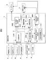
続いて、上述したナビゲーション装置の演算処理部1が有する機能について図2、図3を用いて具体的に説明する。図2は、演算処理部1の機能構成図である。図3は、演算処理部1がユーザから指示された目的地に到着したか否かを判断するための判断基準を設定するために用いる到着判定距離TB451のデータ構造の一例を模擬的に示す図である。
【0026】
図2に示すように、演算処理部1は、位置検出部100、目的地設定部200、表示情報形成部300、経路誘導部400、目的地到着判定条件設定部450、経路選定部500、および目的地到着判定部600を有する。
【0027】
位置検出部100は、車輪速センサ6で計測される距離パルスデータS5およびジャイロセンサ8で計測される角速度データS7を各々積分した結果得られる距離データおよび角度データを用いて、そのデータを時間軸で積分していくことにより、初期値(X,Y)から自車走行後の位置である現在位置(X´,Y´)を定期的に演算し、表示情報形成部300に出力する。ここで、自車の回転した角度と進む方向との関係を一致させるため、地磁気センサ7から得られた方位データS6と、ジャイロ8から得られ角速度データS7を積分した角度データを参照して、自車が進行している方向の絶対方位を推定する。車輪速センサ6のデータS5およびジャイロ8のデータS7を各々積分していくと、誤差が蓄積するため、ある時間でGPS受信装置9から得られた位置データS8をもとに蓄積した誤差をキャンセルする処理を施し、現在位置のデータを表示情報形成部300に出力する。
【0028】
目的地設定部200は、入力装置5を介してユーザから目的地の設定を受けつける。具体的には、目的地設定部200は、目的地の入力を受け付けるための目的地設定画面をディスプレイ2に表示する(表示情報形成部300を介し、ディスプレイ2に目的地設定画面を表示する)。そして、目的地設定部200は、画面上の案内に従いユーザが入力装置5を介して入力する目的地を受け付け、目的地データ(目的地名、目的地のカテゴリ、目的地の位置データ)を設定する。
【0029】
目的地到着判定条件設定部450は、目的地設定部200が受け付けた目的地データを取得し、目的地への到着を判断するための基準値である「到着判定距離」を、取得した目的地データ(目的地名、目的地のカテゴリ、目的地の位置データ)を用いて設定する。具体的には、目的地到着判定条件設定部450は、到着判定距離TB451を有し、受け付けた目的地毎に到着判定距離TB451のデータを用いて「到着判定距離」を設定する。
【0030】
図3は、到着判定距離TB451のデータ構造を模擬的に示したものである。図示するように、到着判定距離TB451は、目的地のカテゴリ毎に対応付けられた到着判定距離が格納されている施設TB452と、特定の施設に対してユーザが個別に設定した到着判定距離が格納されているユーザ登録TB453と、を有し構成されている。
【0031】
施設TB452は、目的地のカテゴリを格納するエントリ460(a、b、c、d、e、h、g、h…)と、エントリ460(a、b、c、d、e、h、g、h…)に対応付けた到着判定距離を格納するエントリ470(a、b、c、d、e、h、g、h…)と、を有している。例えば、エントリ460aには「ガソリンスタンド」が格納されていて、エントリ460aに対応付けたエントリ470aには、「10m」が格納されている(この場合には、設定された目的地が「ガソリンスタンド」の場合には、到着判定距離を「10m」に設定することを示している)。また、例えば、エントリ460bには、「駐車場」が格納されていて、エントリ460bに対応するエントリ470bには「50m」が格納されている(この場合には、設定された目的地が「駐車場」の場合には、到着判定距離を「50m」に設定することを示している)。
【0032】
図示する例では、施設TB452に格納さている目的地のカテゴリに対応付けた到着判定距離は、目的地の有する面積を考慮して定められている。例えば、エントリ460cの「テーマパーク」は、大きな敷地面積を有する場合が多いため、長い到着判定距離(200m)が格納されている(エントリ470c)。このように、大きな面積を有する施設を目的地とする場合、到着判定距離を長い距離(例えば200m)に設定することで、上記特許文献1のように目的地への到着が判断できないという事態を防ぐことができる。また、図示する例では、エントリ460dの「コンビニエンスストア」は、店舗面積が小さい場合が多いことを考慮して、短い到着判定距離(10m)が格納されている(エントリ470d)。このよう、面積の小さい店舗には、短い到着判定距離を設定することで、目的地直近まで運転者を案内することができる(目的地到着の判断処理の手順についは後段で詳細に説明する)。なお、施設TB452のデータは、デフォルトデータとしてナビゲーション装置の提供者により予め格納されるものとする(ユーザがデフォルトデータを変更できるようにしてもよい)。
【0033】
ユーザ登録TB453は、ユーザ自身が特定した目的地毎に施設の「到着判定距離」を設定するために設けたテーブルである(例えば、顧客回りを行なうビジネスユーザの場合、客先毎に「到着判定距離」を設定しておくようにしてもよい)。図示するように、ユーザ登録TB453は、目的地名およびその位置データ(緯度、経度)を格納するエントリ480(a、b、c…)と、エントリ480(a、b、c…)に対応付けた到着判定距離を格納するエントリ490(a、b、c…)とを有する。例えば、ユーザ登録TB453のエントリ480aには、「XYZホテル」および「緯度xy経度zz」が格納され、エントリ480aに対応付けられたエントリ490aには、「30m」が格納されている(この場合には、設定された目的地が「緯度xy経度zzに位置するXYZホテル」の場合には、到着判定距離を「30m」に設定することを示している)。なお、ユーザ登録TB453のデータは、ユーザからの入力を、入力装置5を介して受け付けた目的地到着判定条件設定部450により格納されるものとする。
【0034】
図2に戻り説明を続ける。目的地到着判定部600は、目的地設定部200が受け付けた目的地に到着したか否かの判断を所定の距離間隔或いは時間間隔で行う。
【0035】
経路選定部500は、目的地設定部200が受け付けた目的地、位置検出部100が検出した現在位置、および地図データ記憶装置3が記憶している地図データに基づいて目的地までの経路を選定する。なお、本実施形態では、目的地までの経路を選定する具体的方法については特に限定しないが、例えば、ダイクストラ法により目的地までの経路を選定するようにしてもよい。
【0036】
経路誘導部400は、経路選定部500が選定した経路データおよび記憶装置3が記憶している地図データに基づいて目的地まで誘導する。
【0037】
表示情報形成部300は、地図データ記憶装置3が記憶している地図データを読み出し、位置検出部100が検出した現在位置を中心とした任意の縮尺の地図画像データの生成を行なう。さらに、表示情報形成部300は、経路選定部500が選定した経路を読み出し、上記生成した地図画像データに該経路および現在位置(自車位置)を示すマークを識別可能に重畳してディスプレイ2に出力する。
【0038】
また、表示情報形成部300は、各種の設定画面を表示させる画像データを生成し、ディスプレイ2に出力する(例えば、目的地設定部200から所定のデータを受け付け、目的地設定画面の画像データを生成する)。
【0039】
続いて、演算処理部1のハードウェア構成を説明する。図4は、演算処理部1のハードウェア構成を示す図である。
【0040】
図示するように、演算処理部1は、CPU(中央演算処理装置)21と、CPU21が実行するプログラムやデータを一時的に記憶するRAM(Random Access Memory)22と、上記各機能(位置検出部100、目的地設定部200、表示情報形成部300、経路誘導部400、目的地到着判定条件設定部450、経路選定部500、目的地到着判定部600)を実行するためのプログラムが予め記憶されているROM(Read Only Memory)23と、メモリ間およびメモリと各デバイスとの間のデータを転送するDMA(Direct Memory Access)24と、グラフィック描画を実行し且つ表示制御を行う描画コントローラ25と、グラフィックスイメージデータを蓄えるVRAM(Video Random Access Memory)26と、イメージデータをRGB信号に変換するカラーパレット27と、アナログ信号をデジタル信号に変換するA/D変換器28と、シリアル信号をバスに同期したパラレル信号に変換するSCI(Serial Communication Interface)29と、パラレル信号をバスに同期させてバス上に載せるPIO(Parallel Input/Output)30と、パルス信号を積分するカウンタ31と、を有する。
【0041】
続いて、本実施形態のナビゲーション装置が行なう目的地までの経路誘導処理のフローについて図5を用いて説明する。図5は、本実施形態のナビゲーション装置の目的地への経路誘導処理のフローを説明するための図である。
【0042】
最初に、本ナビゲーション装置は、ユーザから目的地および経由地の設定を受け付け、現在地点から目的地に至るまでの経路の選定を行う(ステップ1)。具体的には、目的地設定部200は、ディスプレイ2に目的地設定画面を表示し、入力装置5を介してユーザが入力するデータに基づいて目的地データ(目的地名、目的地のカテゴリ、位置データ)、および経由地がある場合には経由地データ(経由地名、経由地のカテゴリ、位置データ)を受付ける。目的地設定部200は、上記受け付けた目的地設定データ(目的地データ、および経由地がある場合には経由地データ)を、経路選定部500に出力する。
【0043】
経路選定部500は、目的地設定データの入力を受け付け、該目的地設定データ、位置検出部100が検出した現在位置、および地図データ記憶装置3が記憶している地図データに基づいて目的地までの経路を算出する。そして、経路選定部500は、算出した経路データ(目的地設定データおよび現在位置から目的地までの経路を特定するデータ)を表示情報形成部300に出力する。表示情報形成部300は、該経路データと地図データとを用いて、地図データ上に設定した目的地までの経路および位置検出部100が検出した現在位置を表示した画像データを生成し、ディスプレイ2に表示する。
【0044】
続いて、目的地到着判定条件設定部450は、目的地設定部200から、ステップ1で設定した目的地設定データを取得する。そして、目的地到着判定条件設定部450は、上記取得した目的地設定データと自身が有する到着判定距離TB451に格納されているデータを用いて、目的地(または経由地)まで到着したか否かを判断するための基準値である「到着判定距離」の設定を行う(ステップ2)。
【0045】
より具体的には、目的地到着判定条件設定部450は、上記受け付けた目的地設定データが、到着判定距離TB451のユーザ登録TB453に格納されているか否かを判定する(目的地名(経由地名)および位置データが一致するか否かにより判定する)。そして、目的地到着判定条件設定部450は、取得した目的地設定データの目的地名(経由地名)がユーザ登録TB453に格納されていると判定した場合、格納されているエントリ480に対応するエントリ490の距離を「到着判定距離」と設定する。一方、目的地到着判定条件設定部450は、上記取得した目的地設定データの目的地名(経由地名)がユーザ登録TB453のエントリ480に格納されていない場合、施設TB452に格納されているデータを用いて到着判定距離を設定する(例えば、目的地データ(経由地データ)が有するカテゴリが「テーマパーク」の場合、エントリ460cに対応付けられるエントリ470cの「200m」を設定する)。
【0046】
また、目的地到着判定条件設定部450は、設定した「到着判定距離」をディスプレイ2に表示し、ユーザから該設定した「到着判定距離」の変更の有無を受け付ける。そして、目的地到着判定条件設定部450は、ユーザから入力装置5を介して上記設定した「到着判定距離」の変更を受け付けた場合、上記設定した「到着判定距離」に代えて、ユーザから入力装置5を介して受け付けた距離を「到着判定距離」と設定する。さらに、目的地到着判定条件設定部450は、変更を受け付けた目的地(または経由地)の「到着判定距離」を、ユーザ登録TB453に目的地の名称および位置データ(緯度・経度)に対応付けて格納する(到着判定距離の変更を受け付けた目的地(経由地)が、既にユーザ登録TB453に格納されている場合、そのデータの到着判定距離を更新する)。
【0047】
ステップ2の「到着判定条件」の設定処理が終了した後、経路誘導部400は、経路誘導を開始する(ステップ3)。具体的には、経路誘導部400は、経路選定部500から経路データ(目的地設定データおよび現在位置から目的地までの経路を特定するデータ)を取得し、位置検出部100が検出した現在位置、および地図データ記憶装置3が記憶している地図データに基づいて目的地に至るまでの交差点における右左折案内あるいは直進案内、周辺施設の案内等の経路誘導を音声により(音声入出力装置4の出力により)、或いは映像により(ディスプレイ2上の画像表示に)行なう。
【0048】
ステップ3の経路誘導を開始された後、目的地到着判定部600は、目的地設定部200が受け付けた目的地設定データの中に経由地データがあるか否かを判定し、経由地データが無い場合、ステップ7の処理に進む。一方、目的地到着判定部600は、上記受け付けた目的地設定データの中に経由地データがある場合、ステップ5の処理に進む(ステップ4)。
【0049】
ステップ5では、目的地到着判定部600は、所定の距離間隔あるいは時間間隔で上記経由地に到着したか否かを判断する。具体的には、目的地到着判定部600は、位置検出部100から現在走行中の現在位置データを取得する。さらに、目的地到着判定部600は、目的地到着判定条件設定部450から、ステップ2で設定した該経由地に対応する「到着判定距離」を取得する。そして、目的地到着判定部600は、上記取得した経由地データおよび現在位置に基づいて、経由地と現在位置との距離「X」を算出し、該距離「X」が上記取得した「到着判定距離」以下の場合(X≦「到着判定距離」)に、上記経由地に到着したものと判断し、その旨を示す音声データを音声入出力装置4に出力させる(或いはその旨を示す画像データをディスプレイ2に表示する)。なお、目的地到着判定部600は、到着した経由地データを「通過完了」データとして、未到着の経由地データと識別可能に管理する。一方、目的地到着判定部600は、上記算出した距離が上記取得した「到着判定距離」より大きい場合(X>「到着判定距離」)、上記経由地にまだ到着していないものと判断し、ステップ5の処理を繰り返す。
【0050】
ステップ6では、目的地到着判定部600は、取得した経由地データの中に未到着の経由地データがあるか否かを判定する。そして、目的地到着判定部600は、未到着経由地があると判定した場合、ステップ5に戻り、未到着経由地がないと判定した場合には、ステップ7の処理に進む。
【0051】
ステップ7では、目的地到着判定部600は、ステップ5で説明した経由地到着の判断と同様の手順により目的地に到着したか否かの判断を行う。
【0052】
ステップ8では、目的地到着判定部600は、目的地に到着したことを示す音声データを音声入出力装置4に出力させ、或いは目的地に到着したことを示す画像データを、表示情報形成部300を介してディスプレイ2に表示し、処理を終了する。
【0053】
このように、本実施形態では、ナビゲーション装置が目的地毎に目的地到着
を判断する基準値(到着判定距離)を設定し、その基準値(到着判定距離)を用いて目的地に到着したか否かを判断している。すなわち、本実施形態では、設定した目的地が、ユーザが個別に登録している特定の施設の場合、その登録された特定の施設に対応する基準値(到着判定距離)を用いて目的地の到着を判断し、設定した目的地が上記特定の施設に該当しない場合、設定された目的地のカテゴリで設定した基準値(到着判定距離)を用いて目的地への到着を判断している。したがって、本第1の実施形態によれば、目的地まで到着したか否かを設定した目的地の事情を考慮して判断することができる。
【0054】
また、本実施形態のナビゲーション装置は、ユーザが特定の施設毎に任意の到達判定距離を設定することができるユーザ登録TB453を有している。そのため、個々のユーザに応じた目的地の案内をすることができる。また、本実施形態では、上記カテゴリにより設定された到着判定距離の変更をユーザから受け付けた場合、その目的地のデータをユーザ登録TB453に格納するようにしている。そのため、本実施形態のナビゲーション装置は、ユーザが利用する毎にカスタマイズされ、ユーザの利便性を向上させることができる。
【0055】
次に、図6〜図8を用いて、本第1の実施形態のナビゲーション装置の目的地までの経路誘導処理について、具体的な例を挙げて説明する。
【0056】
図6は、本第1の実施形態のナビゲーション装置の目的地までの経路誘導処理のフローを、具体例を挙げて説明するための図である。図7は、目的地および経由地の設定画面の遷移の一例を示す図である。図8は、到着判定距離をユーザが設定する場合の設定画面の遷移の一例を示す図である。
【0057】
最初に目的地設定部200は、図5で説明したステップ1と同じ処理を行う(ステップ10)。ここで、目的地設定部200は、例えば、図7に示す設定画面(511〜518)をディスプレイ2に表示し、目的地および経由地の設定を受け付ける。図示すように、本第1の実施形態のナビゲーション装置は、目的地が設定される前に、例えば、地図上に現在位置を示した地図画面510をディスプレイ2に表示する。そして、目的地設定部200は、入力装置5の所定の入力を受け付けた場合、図示する各種の設定画面(511〜518)をディスプレイ2に表示する。
【0058】
目的地設定部200は、ナビゲーション装置全体のメニューを示す設定画面511上で、目的地設定511aの選択を受け付けた場合、目的地設定メニューを示す設定画面514を表示する。図示する例では、設定画面514は、目的地の設定を受け付ける項目として、地図514a、施設514b、名称514c、住所514d、および電話番号514eを有している。そして、目的地設定部200は、設定画面514上で受け付けた項目で目的地の設定を行う(例えば、電話番号の入力を受け付けて目的地を設定する)。なお、本第1の実施形態では、目的地設定部200の目的地を設定する具体的な手順については特に限定しない。地図データ記憶装置3に所定の目的地設定データベースを保持させておいて、入力設定部200が、例えば、目的地の電話番号の入力を受け付けた場合、その電話番号および上記目的地設定データベースに基づいて目的地データ(目的地名、目的地のカテゴリ、位置データ)を作成し、指定した目的地の地点を設定画面518に表示するようにしてもよい。また、目的地設定部200は、例えば、通信手段(図示せず)を用いて所望の目的地データを外部から取得し、該取得した目的地データを設定画面518の地図上に表示するようにしてもよい。
【0059】
目的設定部200は、目的地の設定を受け付けた場合、行き先リストを示す設定画面512を表示し、目的地までの経路の経由地の設定を受け付ける。この経由地の設定は、目的地の設定と同様の経由地設定メニューを示す設定画面513を表示し、経由地データ(経由地名、経由地のカテゴリ、経由地の位置データ)の設定を受け付ける。なお、図示する例では、目的地設定部200は、設定画面512に示すように最初に経由地1の「GHIガソリンスタンド」を通り、次に経由地2の「DEFレストラン」を通り目的地「ABCホテル(観光ホテルとする)」に向かうルートの設定を受け付けたことを示している。
【0060】
図6に戻り説明を続ける。ステップ10で目的地および経由地の設定を受け付けた場合、目的地到着判定条件設定部450は、図5に示すステップ2で説明した「到着判定距離」の設定を行う。ここでは、目的地到着判定条件設定部450は、ステップ10で目的地設定部200が設定した目的地の「ABCホテル」、経由地2の「DEFレストラン」、および経由地1の「GHIガソリンスタンド」の「到着判定距離」の設定を行う。なお、「ABCホテル」、「GHIガソリンスタンド」および「DEFレストラン」はいずれもユーザ登録TB453(図3)に格納されているデータに該当しないものとする。そのため、目的地到着判定条件設定部450は、施設TB452のデータに基づいて「到着判定距離」を設定する。
【0061】
具体的には、目的地の「ABCホテル」は、カテゴリが「観光ホテル」であるため、図3のエントリ460eに対応するエントリ470eに格納されている「100m」が「到着判定距離」として設定される。経由地1の「GHIガソリンスタンド」は、カテゴリがガソリンスタンドであるため、図3のエントリ460aに対応するエントリ470aに格納されている「10m」が到着判定距離として設定される。経由地2の「DEFレストラン」は、カテゴリがレストランであるため、図3のエントリ460hに対応するエントリ470hに格納されている「30m」が「到着判定距離」として設定される。
【0062】
続いて、目的地到着判定条件設定部450は、設定した「到着判定距離」を、設定画面519(図8)に示し、ユーザから該設定した「到着判定距離」の変更の有無を受け付ける。例えば、目的地到着判定条件設定部450は、図8に示す設定画面520、521を順番にディスプレイ2に表示し、デフォルトで設定されている到着判定距離の変更を受け付ける。図示する設定画面521では、経由地1の「GHIガソリンスタンド」の到着判定距離は、デフォルトの「10m」から、「20m」に変更されたことを示している。なお、この場合、目的地到着判定条件設定部450は、上記変更した値(20m)を、「GHIガソリンスタンド」および位置データ(GHIガソリンスタンドの緯度、経度)に対応付けてユーザ登録TB453(図3)に格納する。そして、変更を受け付けた目的地(施設)のデータをユーザ登録TB453に格納しておくことで、次に「GHIガソリンスタンド」が、目的地(又は経由地)として設定された場合、この変更した到着判定距離が設定されることになる。そのため、本第1の実施形態のナビゲーション装置は、ユーザの利用によりカスタマイズされ、ユーザの利便性を向上させることができる。
【0063】
また、目的地到着判定条件設定部450は、具体的に目的地を設定する処理の過程に関係なく、つまり図6に示すステップ11の処理とは関係なく、図8に示す設定画面521をディスプレイ2に表示し、ユーザから特定の施設に対する到着判定距離の入力を受付け、ユーザ登録TB453(図3)に受け付けたデータを格納するように構成されている。したがって、特定の施設に対しては、ユーザにとって最適な「到着判定距離」を設定しておくことで、個々のユーザに対応した最適なナビゲーション装置が構築される(例えば、ビジネスに利用する場合、迷いやすい場所にある顧客先に対し、早めに目的地付近に到着していることが告知されるように到着判定距離を長く設定しておことで効率よく、その顧客先に到着することができる)。
【0064】
図6に戻り説明を続ける。ステップ11の後、経路誘導部400は、図5のステップ3〜4と同様の処理を行う(ステップ12、13)。なお、ここでは、経由地は2箇所(「GHIガソリンスタンド」および「DEFレストラン」)設定されているため、目的地到着判定部600は、ステップ14の処理に進む。
【0065】
ステップ14では、経路誘導部400は、「GHIガソリンスタンド」まで誘導を開始する。そして、目的地到着判定部600は、図5のステップ5の処理、すなわち、所定の距離間隔或いは時間間隔で経由地1の「GHIガソリンスタンド」に到着しているか否かの判断を行う(ステップ15)。ここでは、ステップ11で目的地到着判定条件設定部450が設定した「GHIガソリンスタンド」に対応する到着判定距離が「20m」であるため(デフォルトの値から変更されているため)、目的地到着判定部600は、位置検出部100が検出した現在位置と「GHIガソリンスタンド」との距離「X」が、「20m」以内(X≦「20m」)であるか否かを判定し、「20m」以内の場合、経由地1の「GHIガソリンスタンド」に到着したものと判断しステップ16に進む。一方、目的地到着判定部600は、上記距離「X」が、「20m」より大きい場合(X>「20m」)、上記経由地1にはまだ到着していないものと判断し、ステップ15の処理を繰り返す。
【0066】
ステップ16では、目的地到着判定部600は、経由地1に到着した旨(例えば、「間もなくGHIガソリンスタンドに到着します」等の音声メッセージ)を、音声入出力装置4を介して出力する。
【0067】
ステップ17では、目的地到着判定部600は、図5のステップ6と同じ処理をおこなう。なお、ここでは、経由地2の「DEFレストラン」にまだ到着していないため、ステップ18に進む。ステップ18では、経路誘導部400は、「DEFレストラン」まで誘導を開始し、ステップ19に進む。
【0068】
ステップ19では、目的地到着判定部600は、所定の距離間隔或いは時間間隔で経由地2の「DEFレストラン」に到着しているか否かの判断を、ステップ11で設定した「DEFレストラン」に対応する到着判定距離を用いて行う。具体的には、ステップ11で設定した「DEFレストラン」に対応する到着判定距離が「30m」であるため、目的地到着判定部600は、位置検出部100が検出した現在位置と「DEFレストラン」との距離「X」が、「30m」以内(X≦「30m」)であるか否かを判定する。そして、目的地到着判定部600は、上記距離「X」が「30m」以内の場合には、経由地2の「DEFレストラン」に到着したものと判断し、ステップ20に進む。一方、目的地到着判定部600は、上記距離「X」が「30m」より大きい場合(X>「30m」)、上記経由地2にまだ到着していないものと判断し、ステップ19の処理を繰り返す。
【0069】
ステップ20では、目的地到着判定部600は、経由地2に到着した旨(例えば、「間もなくDEFレストランに到着します」等の音声メッセージ)を、音声入出力装置4を介して出力し、ステップ21に進む(なお、本具体例では、未到着の経由地は無いため図5のステップ6の説明は省略する)。その後、経路誘導部400は、「ABCホテル」まで誘導を開始し、ステップ22に進む(ステップ21)。
【0070】
ステップ22では、目的地到着判定部600は、図5のステップ7と同様の処理、すなわち、所定の距離或いは時間毎に目的地である「ABCホテル」に到着しているか否かの判断を行う。ここで、ステップ11で目的地到着判定条件設定部450が設定した「ABCホテル」に対応する到着判定距離が「100m」であるため、目的地到着判定部600は、位置検出部100が検出した現在位置と「ABCホテル」との距離「X」が、「100m」以内(X≦「100m」)であるか否かの判定を行う。そして、目的地到着判定部600は、上記距離「X」が「100m」以内の場合、目的地の「ABCホテル」に到着したものと判断しステップ23に進む。一方、目的地到着判定部600は、上記距離「X」が、「100m」より大きい場合(X>「100m」)、上記目的地にはまだ到着していないものと判断し、ステップ22の処理を繰り返す。
【0071】
ステップ23では、目的地到着判定部600は、目的地に到着した旨(例えば、「間もなくABCホテルに到着します」等の音声メッセージ)を、音声入出力装置4を介して出力し、処理を終了する。
【0072】
このように、本実施形態では、設定した目的地(経由地)のカテゴリ毎に目的地に到着したか否かを判断する基準値(到着判定距離)を設定し、その設定した基準値(到着判定距離)により、目的地(経由地)への到着を判断している。また、この目的地のカテゴリ毎の基準値は、目的地の面積が考慮されている。例えば、目的地の「ABCホテル」は、カテゴリが「観光ホテル」であるため、「到着判定距離」として「100m」が設定される(観光ホテルは敷地面積が大きい場合が多いため、長い到着判定距離が設定されるように構成されている)。したがって、本実施形態では、目的地の面積が大きい場合でも、目的地の到着を判断して運転者にその旨を告知することができる(目的地の面積が広い場合、到着判定距離が長く設定されているため)。また、面積の大きい施設は、入り口に通じる経路(道路)が特定される場合もあるため、早く運転者に目的地に近づいていることを告知することで、不要な運転を防ぐことができる(例えば、目的地付近に到着してから、目的地の入り口まで迂回する運転を防ぐことができる)。
【0073】
また、例えば、目的地が「DEFレストラン」は、カテゴリが「レストラン」であるため到着判定距離に「30m」に設定される(一般的にレストランは、観光ホテルに比べて面積が小さいため、上記「ABCホテル」より短い到着判定距離が設定されている)。そのため、「DEFレストラン」近くまで、運転者を案内することができる。
【0074】
続いて、本発明の第2の実施形態について説明する。本発明の第2の実施形態のナビゲーション装置は、目的地のカテゴリに加え、さらに目的地につながる移動経路の道路種別も考慮に入れて、目的地に到着したか否かを判断するように構成したものである。
【0075】
さて、本第2の実施形態のナビゲーション装置の概略構成は図1で示した第1の実施形態と同じである。本第2の実施形態の演算処理部1のハードウェア構成は、図4で示した第1の実施形態のものと同じである。また、本第2の実施形態のナビゲーション装置の演算処理部1の機能構成は、図2に示す上記第1の実施形態のものと目的地設定部200および目的地到着判定条件設定部450が行う処理の一部が異なる以外は同じである。なお、本第2の実施形態の説明では、上記の第1の実施形態と同じ構成については、同じ符号を用いることとする(目的地設定部および目的地到着判定条件設定部についても同じ符号を用いる)。
【0076】
最初に本第2の実施形態の機能構成のうち第1の実施形態と異なる目的地設定部200および目的地到着判定条件設定部450を説明する。
【0077】
本第2の実施形態の目的地設定部200は、目的地および経由地を受け付ける場合、上記第1の実施形態と同様に、目的地名(経由地)、目的地(経由地)のカテゴリ、および目的地(経由地)の位置データを設定する処理を行い、さらに目的地(経由地)につながる移動経路の道路種別についても設定する。そして、目的地設定データ(目的地名、目的地のカテゴリ、目的地の位置データ、道路種別)を、目的地到着判定条件設定部450に出力する。
【0078】
本第2の実施形態の目的地到着判定条件設定部450は、第1の実施形態の目的地到着判定条件設定部450が有する到着判定距離TB451と異なるデータ構造の到着判定距離TB451bを有する。そして、目的地到着判定条件設定部450は、目的地設定部200から取得した目的地設定データおよび到着判定距離TB451bのデータに基づいて「到着判定距離」を設定する。
【0079】
続いて、到着判定距離TB451bのデータ構造について説明する。図9は、本第2の実施形態の到着判定距離TB451bのデータ構造の一例を模擬的に示した図である。図示するように、到着判定距離TB451bは、第1と同様の施設TB452およびユーザ登録TB453を有し、さらに道路種別TB454を有して構成されている。
【0080】
道路種別TB454は、道路のカテゴリを格納するエントリ500(a、b、c、d、e…)と、エントリ500(a、b、c、d、e…)に対応付けた「到着判定距離」を格納するエントリ510(a、b、c、d、e、h、g、h…)と、を有する。この、道路種別TB454に格納さている道路種別に対応付けた到着判定距離は、道路種の走行可能な速度を考慮して定められている。
【0081】
図示する例では、エントリ500aには「高速道路、有料道路」が格納されていて、エントリ500aに対応付けたエントリ510aには、到着判定距離「300m」が格納されている(高速走行のため、長い到着判定距離を定めて早期に目的地への到着を運転者に告知できるようにしている)。また、図示する例では、エントリ500b、c、d、eに格納されている「国道」、「県道、主要地方道」、「一般道」、「細街路」には、それぞれの走行速度を考慮した「到着判定距離」が格納されている(エントリ510b、c、d、e)。なお、図示する例は、あくまで例示であり、本実施形態は特にこれに限定しない。例えば、県道であっても、慢性的に渋滞する道路については、図示する例より短い到着判定距離を格納するようにしても良い。また、一般道であっても、交通量が少なく、信号も無い道路には、図示する例より長い到着判定距離を格納するようにしてもよい。なお、道路種別TB454のデータは、デフォルトデータとしてナビゲーション装置の提供者により予め格納されるものとする(ユーザがデフォルトデータを変更できるようにしてもよい)。
【0082】
本第2の実施形態のナビゲーション装置が行なう目的地までの誘導処理のフローは、基本的に図5に示す第1の実施形態のものと同じである。但し、ステップ1において、目的地(経由地)の設定を行う場合に、その目的地(経由地)につながる道路種別の設定も行う点と、ステップ2において、目的地のカテゴリと上記目的地につながる道路種別を用いて、目的地への到着を判断する基準値(到着判定距離)を設定する点が異なっている。
【0083】
なお、目的地到着判定条件設定部450は、上記目的地設定データの目的地(経由地)がユーザ登録TB453のエントリ480に格納されていない場合、以下の手順で「到着判定距離」の設定を行う。
【0084】
まず、目的地到着判定条件設定部450は、取得した目的地設定データが有する道路種別および道路種別TB503に基づいて仮の「到着判定距離」を特定する。次に、目的地到着判定条件設定部450は、取得した目的利設定データが有する目的地のカテゴリおよび施設TB452に基づいて仮の「到着判定距離」を特定する。そして、目的地到着判定条件設定部450は、上記特定した2つの仮の「到着判定距離」を比較し、長い距離のデータを正式の「到着判定距離」として選択して設定する。なお、本説明では、上記特定した2つの仮の「到着判定距離」の中から長い方の距離を選択し、選択した距離を正式の「到着判定距離」として設定するようにしているが、これは例示に過ぎず他の方法で「到着判定距離」を選択するようにしてもよい。
【0085】
続いて、図10、図11を用いて、本第2の実施形態のナビゲーション装置の目的地までの経路誘導処理について、具体的な例を挙げて説明する。
【0086】
図10は、本第2の実施形態のナビゲーション装置の目的地までの経路誘導処理のフローを、具体例を挙げて説明するための図である。図11は、目的地および経由地の設定画面の一例を示す図である。
【0087】
図示するように、最初に、上述した図6のステップ10と同様に目的地、経由地、および経路選定を行う(ステップ30)。そして、目的地設定部200は、目的地および経由地の設定する場合、例えば、図11に示す各種の設定画面(811〜818)をディスプレイ2に表示し、目的地および経由地の設定を受け付ける。また、目的地設定部200は、目的地を目的地(経由地)につながる道路種別に対応付けて設定する(設定画面818)。なお、目的地と道路種別との対応付ける方法については、特に限定しないが、例えば、目的地設定部200は、経路選定部500が算出した経路データにより目的地につながる道路種別を特定して、該目的地と道路種別を対応付けて設定してもよい。
【0088】
なお、本具体例では、図示するように経由地1に「細街路沿いのバス停A」が設定され、経由地2に「高速道路沿いのバス停B」を設定され、目的地に「国道沿いにある遊園地」が設定されている(設定画面812、818)。
【0089】
ステップ31では、目的地到着判定条件設定部450は、上述したように、目的地のカテゴリだけでなくその目的地につながる道路種別についても考慮して、「到着判定距離」を設定する。より具体的には、目的地到着判定条件設定部450は、目的地設定部200が受け付けた目的地設定データ(「細街路沿いのバス停A」、「高速道路沿いのバス停B」、および「国道沿いにある遊園地」のそれぞれの、目的地名、目的地のカテゴリ、目的地の位置データ、道路種別)を取得する。なお、ここでは、取得した目的地および経由地は、ユーザ登録TB453(図9参照)に格納されているデータに該当しないものとする。そのため、目的地到着判定条件設定部450は、施設TB452および道路種別TB454を用いて「到着判定距離」を設定する。
【0090】
上記経由地1は、道路種別が「細街路」で施設のカテゴリが「バス停」である。そのため、目的地到着判定条件設定部450は、道路種別「細街路」および道路種別TB454から仮の到着判定距離「20m」を特定(エントリ500eに対応付けられているエントリ510eに格納されているデータを特定する)し、カテゴリ「バス停」および施設TB452から仮の到着判定距離「20m」を特定(エントリ460fに対応付けられているエントリ470fに格納されているデータを選定する)する。そして、目的地到着判定条件設定部450は、上記特定した2つの仮の到着判定距離から「細街路沿いのバス停A」の正式の到着判定距離を「20m」と設定する(両者が同じ距離であるため)。
【0091】
上記経由地2は、道路種別が「高速道路」で施設のカテゴリが「バス停」である。そのため、目的地到着判定条件設定部450は、道路種別「高速道路」および道路種別TB454から仮の到着判定距離「300m」を特定(エントリ500aに対応付けられているエントリ510aに格納されているデータを特定する)し、カテゴリ「バス停」および施設TB452から仮の到着判定距離「20m」を特定する。そして、目的地到着判定条件設定部450は、上記特定した2つの仮の到着判定距離から「高速道路沿いのバス停B」の正式の到着判定距離として「300m」を設定する(上述したように、特定した2つの仮の到着判定距離の中から長い距離を選択して設定する)。
【0092】
上記目的地は、道路種別が「国道」で施設のカテゴリが「遊園地」である。そのため、目的地到着判定条件設定部450は、道路種別「国道」および道路種別TB454から仮の到着判定距離「100m」を特定(エントリ500bに対応付けられているエントリ510bに格納されているデータを特定する)し、カテゴリ「遊園地」および施設TB452から仮の到着判定距離「200m」を特定(エントリ460cに対応付けられているエントリ470cに格納されているデータを特定する)する。そして、目的地到着判定条件設定部450は、上記2つの仮の到着判定距離から「国道沿いの遊園地C」の正式の到着判定距離として「200m」を設定する(上述したように、特定した2つの仮の到着判定距離の中から長い距離を選択して設定する)。
【0093】
その後、図6で説明したステップ12〜23と同様の処理を行い(ステップ32〜43)、経由地1、2を経由して目的地である「遊園地C」までユーザを誘導する。
【0094】
このように、本第2の実施形態では、施設のカテゴリに加えて道路種別を考慮して到着判定距離を設定している。例えば、高速道路や有料道路のような高速で走行する道路沿いの施設を目的地とする場合は、到着判定距離を長い距離に設定することで、早めにユーザに目的地付近に到着していることを告知し、目的地を通過することがないように注意を促すことができる。
【0095】
また、細街路沿いの施設を目的地とする場合、到着判定距離を短い距離に設定することで、適切に目的地までユーザを誘導することができる(細街路は低速で走行するため、ユーザに目的地の直前で到着の告知をしても、ユーザが目的地に気付かず通過する場合は少ない。また、住宅地等の細街路は、道が複雑な場合もあるため、目的地付近までユーザを誘導する方が正確に目的地までユーザを誘導できる)。
【0096】
なお、本発明は以上で説明した実施形態に限定されるものではなく、本発明の要旨の範囲内において種々の変形が可能である。
【0097】
例えば、上記第2の実施形態では、目的地への到着を判断するための到着判定距離を「道路の種類」により設定するようにしているが、目的地につながる道路の幅により到着判定距離を変更するように構成してもよい。具体的には、目的地到着判定条件設定部450に、図9で示した、道路種別TB454に代えて、道路幅に応じて到着判定距離が定められているテーブルを保持させておく(目的地につながる道路の道路幅が所定の幅より広い場合、所定の幅より狭い道路幅の道路で設定する「到着判定距離」よりも長い「到着判定距離」を設定する)。そして、上記第2の実施形態と同様に、施設TB452(図9)で特定される目的地のカテゴリにより定まる到着判定距離と、道路幅により定まる到着判定距離とを比較して、距離が長い方を「到着判定距離」として設定し、その設定した到着判定距離を用いて目的地への到着を判断する。このように構成することで、走行速度が速い傾向にある道路幅の広い道路沿いの目的地に対しては、早くユーザに目的地への到着を告知できる。したがって、ユーザが目的地を通り過ぎることを防ぐことができる。また、走行速度が遅い傾向にある道路幅の狭い道路沿いの目的地に対しては、目的地の直近(例えば20m)でユーザに到着を告知できるため、より正確にユーザを目的地まで案内できる。
【0098】
さらに、複数車線を有する道路では、自車が左側の車線を走行している場合に設定する「到着判定距離」に比べ、自車が右側よりの車線を走行している場合に設定する「到着判定距離」を長い距離に設定するようにしてもよい。
【0099】
このように構成することで、複数車線を有する道路の右側よりの車線を走行中の運転者に対し、左側車線走行中の場合に比べ目的地への到着を早めに告知できる。したがって、ユーザは余裕を持って車線変更を行い目的地に向かうことができる(右側車線走行中に目的地に近づいた場合には、車線変更する必要があるため)。
【0100】
また、上記第1の実施形態では、目的地のカテゴリに応じて到着判距離を設定するようにしているが、それに加えて当日の天候により設定する「到着判定距離」を変更するようにしてもよい。この場合、ナビゲーション装置に運転中の天候を示すデータを取得する機能を設けておく(例えば、自動車のワイパーに設けられた天候センサからデータを取得する機能や通信手段により外部から天候データを取得する機能を設ける)。さらに、目的地到着判定条件設定部450が有する到着判定距離TB451に、天候毎(「晴れ」、「雨」、「雪」等)の到着判定距離を格納しておく。例えば、図3で示す、施設TB452のエントリ460に対応する各エントリ470に「晴れ」、「雨(雪)」等の天候毎にそれぞれ到着判定距離を格納する(「晴れ」には「雨(雪)」に比べて短い到着判定距離を格納し、「雨や雪」には「晴れ」に比べて長い到着判定距離を格納する)。目的地到着判定部600は、所定の間隔で目的地の到着を判断する場合、天候情報を取得し、取得した天候情報に対応する到着判定距離を目的地到着判定条件設定部450から取得する。そして、目的地到着判定部600は、その取得した「到着判定距離」を用いて目的地への到着の判断を行う。このように構成することで、雨や雪などの悪天候での運転中のユーザに対し、早めに目的地に近づいていることを告知できるため(天候が良い場合に比べ長い到着判定距離が設定されているため)、ユーザが目的地を通り過ぎることを防止することがきる。
【0101】
また、上記の天候データに代え、或いは天候データをとともに運転時刻を到着判定距離の設定に反映させるようにしてもよい。この場合、目的地到着判定条件設定部450が有する到着判定距離TB451に時間毎の到着判定距離を格納しておく(例えば、目的地のカテゴリが観光ホテルの場合、夜間には長い到着判定距離(200m)を設定し、昼間には短い到着判定距離(100m)を設定する)。目的地到着判定部600は、所定の間隔で目的地の到着を判断する場合、時刻データを取得し、取得した時刻データに対応する到着判定距離を目的地到着判定条件設定部450から取得する。そして、目的地到着判定部600は、その取得した到着判定距離を用いて目的地への到着の判断を行う。このように構成することで、運転時間に応じて目的地への到着を判断できるため、高い精度で目的地まで案内することができる(視界の悪い夜間は、早めに目的地への到着を告知し、視界の良い昼間には、目的地の直近で目的地への到着を告知できる)。
【0102】
また、目的地到着判定条件設定部450に速度に応じた到着判定距離が格納されている到着判定距離TB451(「高速度」には、「低速度」に比べて、長い到着判定距離を格納する)を設け、現在走行中の速度に応じて到着判定距離を定めるようにしてもよい。
【0103】
また、到着判定距離を判断する基準を、自動車の運転者毎に設定するようにしてもよい。例えば、本実施形態のナビゲーション装置にシートポジションやステアリングポジションを示すデータ(以下において「運転席データ」という)を取得する機能を設けておく。さらに、目的地到着判定条件設定部450の到着判定距離TB451には、予め「運転席データ」に対応した複数種の到着判定距離TB451を設けておく(「運転席データ」により、運転レベルを初級、中級、上級に分け、そのレベル毎の到着判定距離TB451を設ける)。そして、目的地到着判定条件設定部450は、取得した運転席データに対応した到着判定距離TB451(運転レベルに応じた到着判定距離TB451)を用いて到着判定距離の設定を行うようにする。
【0104】
このように構成することで、自動車を運転する運転者の運転レベルに応じて目的地までの誘導を行うことができる(上級者は、目的地直前で目的地到着を告知されても通り過ぎることが少ない。一方、初級者には早めの到着を告知して注意を喚起する必要がある)。
【0105】
また、ナビゲーション装置の目的地到着判定条件設定部450の到着判定距離TB451にビジネスユーザ(タクシ、宅配便等)を想定した「到着判定距離」を格納したテーブルと、パーソナルユーザを想定した「到着判定距離」を格納したテーブルとを保持させ、ユーザに応じて到着判定距離を設定するようにしてもよい。この場合、「ビジネスユーザ用」の到着判定距離は、「パーソナルユーザ用」のものより短い距離を格納しておく。そして、このように構成することで、運転に慣れているビジネスユーザに対し、目的地到着を目的地の直近で告知できるため精度高くユーザを目的地まで案内することができる。
【0106】
また、ナビゲーション装置が搭載される自動車の種類(大型トラック、普通自動車等)に応じて到着判定距離を設定するようにしてもよい。例えば、目的地到着判定条件設定部450に自動車の種類毎に定めた到着判定距離が格納されている到着判定距離TB451を設けておいて、搭載されている自動車により到着判定距離を設定するようにしてもよい。この場合、小回りの効かない大型車に対しては、「到着判定距離」を普通自動車に比べて長い距離で設定しておく。このように構成することで、小回りの効かない大型トラックの運転者に対して、早めに目的地への到着を告知し注意を喚起することができる。
【0107】
さらに、到着判定距離を、上述した「目的地のカテゴリ」、「道路種別」、「道路幅」、「天候」、「運転席データ」、「運転時間」、「走行車線」、「自動車種別」、および「ユーザ別(ビジネスユーザ用とパーソナルユーザ用)」のすべてを考慮して設定するようにしてもよい。また、これらのいずれかひとつ以上の自由な組み合わせにより到着判定距離を設定するようにしてもよい。そして、複数のデータをパラメータにして到着判定距離を設定する場合には、例えば、それぞれのパラメータにより特定される到着判定距離の中から一番長い距離の到着判定距離を用いて、目的地の到着を判断するようにしてもよい。
【0108】
また、上記実施形態では、地図データを自身が有する地図データ記憶装置から読み出す場合を例に説明したが、これに限定されるものではない。例えば、情報センタ等から地図データを取得するように構成してもよい。また、目的地までの経路選定についても外部で行うように構成し、選定された経路データを通信手段により取得するように構成されていてもよい。
【0109】
【発明の効果】
以上説明したように、本発明によれば、運転者を目的地まで最適に案内するナビゲーション装置を提供することができる。
【図面の簡単な説明】
【図1】本発明の第1の実施形態が適用された車載用ナビゲーション装置の概略構成図である。
【図2】本発明の第1の実施形態の演算処理部1の機能構成図である。
【図3】到着判定距離TB451のデータ構造の一例を模擬的に示す図である。
【図4】本発明の第1の実施形態の演算処理部1のハードウェア構成を示す図である。
【図5】本発明の第1の実施形態のナビゲーション装置の目的地への誘導処理のフローを説明するための図である。
【図6】本第1の実施形態のナビゲーション装置の目的地までの経路誘導処理のフローを、具体例を挙げて説明するための図である。
【図7】本発明の第1の実施形態の目的地および経由地の設定画面の遷移の一例を示す図である。
【図8】到着判定距離をユーザが設定する場合の設定画面の遷移の一例を示す図である。
【図9】本発明の第2の実施形態の到着判定距離TB451bのデータ構造の一例を模擬的に示した図である。
【図10】本発明の第2の実施形態のナビゲーション装置の目的地までの経路誘導処理のフローを、具体例を挙げて説明するための図である。
【図11】本発明の第2の実施形態の目的地および経由地の設定画面の遷移の一例を示す図である。
【符号の説明】
1…演算処理部、2…ディスプレイ、3…地図データ記憶装置、4…音声入出力装置、5…入力装置、6…車輪速センサ、7…地磁気センサ、8…ジャイロ、9…GPS受信装置、21…CPU、22…RAM、23…ROM、24…DMA、25…描画コントローラ、26…VRAM、27…カラーパレット、28…A/D変換器、29…SCI、30…PIO、31…カウンタ、100…位置検出部、200…目的地設定部、300…表示情報形成部、400…経路誘導部、450…目的地到着判定条件設定部、451…到着判定距離TB、500…経路選定部、600…目的地到着判定部[0001]
BACKGROUND OF THE INVENTION
The present invention relates to a technology of a navigation device that guides a route to a destination.
[0002]
[Prior art]
The navigation device receives an input of a destination from the user, displays a route to the received destination, guides the driver to the destination, and determines whether or not the input destination has been reached. There is something to do. When the navigation device determines that the vehicle has arrived at the destination, the navigation device notifies the driver (for example, the driver is notified by voice guidance).
[0003]
The conventional navigation device calculates the distance between the destination and the position of the vehicle currently traveling, and determines that the destination has been reached when the distance falls within a preset reference value. There is a thing (for example, patent document 1).
[0004]
In addition, the conventional navigation device calculates the guidance route to the accepted destination, selects the link closest to the destination among the individual links constituting the guidance route, and then selects the link from the destination to the link. There is one that sets a reference value for determining whether or not the vehicle has arrived at the destination in accordance with the length of the vertical line after dropping the vertical line (for example, Patent Document 2). The navigation device disclosed in
[Patent Document 1]
Japanese Patent Laid-Open No. 7-55483
[Patent Document 2]
JP-A-8-159796
[0005]
[Problems to be solved by the invention]
However, the technique disclosed in
[0006]
Moreover, the technique of the said
[0007]
The present invention has been made in view of the above circumstances, and an object thereof is to provide a navigation device that optimally guides a driver to a destination.
[0008]
[Means for Solving the Problems]
In order to solve the above-described problem, an aspect of the present invention is directed to a vehicle-mounted navigation device that displays a vehicle position on map data and provides route guidance to a destination, and a position detection unit that detects the vehicle position; An input means for receiving an input of a destination, a route selection means for selecting a travel route to the received destination, a guide means for guiding the vehicle based on the selected route, and arrival at the destination And a determination means for determining. Then, the determination means specifies a reference value corresponding to the received destination type from among reference values for determining arrival at a predetermined destination for each type of destination, and the vehicle When the distance between the position and the destination is within the specified reference value, it is determined that the destination has arrived.
[0009]
Thus, according to this aspect, the reference value for determining arrival at the destination is set for each type of destination. Therefore, for example, when a facility having a vast site is set as the destination, it is possible to prevent a situation in which arrival at the destination cannot be determined as in
[0010]
Further, according to this aspect, the reference value is not determined from the distance between the road on the map and the destination as in
[0011]
In addition, the determination means replaces the type of destination received from the reference value for determining arrival at a destination predetermined for each road type, instead of the type of destination received. A reference value corresponding to the type of road is specified, and when the distance between the vehicle position and the destination is within the specified reference value, it is determined that the destination has arrived. Also good. By configuring in this way, for example, when the road type of the travel route leading to the destination is an expressway, the reference value is set to a longer distance than a general road such as a national road or a prefectural road, so that the arrival at the destination Can be judged quickly. Therefore, it is possible to prevent the driver from passing through without finding the destination (because it is necessary to notify the driver that he / she is near the destination at an early stage because of high speed driving). On the other hand, for example, when the road type of the travel route leading to the destination is a narrow street, the driver can be guided to the vicinity of the destination by setting the reference value short (the narrow street is driven at a low speed). Therefore, there are few cases where you will pass through your destination even if you have arrived most recently.)
[0012]
Further, the determination means includes the type of destination, the type of road of the travel route leading to the destination, the type of road width of the travel route leading to the destination, the type of weather during driving, the type of time during driving, Based on at least one of the types of lanes in which the host vehicle is traveling, the type of driving level of the driver, and the type of host vehicle, from among the reference values predetermined for each of the at least one type, A reference value applied to determine arrival at the accepted destination is specified, and the received destination is determined when the distance between the vehicle position and the destination is within the specified reference value. It is also possible to judge that it has arrived.
[0013]
In this way, the reference value for arriving at the destination can be obtained from various types of information (type of destination, type of road of the moving route leading to the destination, type of road width of the moving route leading to the destination, weather during driving, etc. Type, time of driving, type of lane in which the vehicle is traveling, type of driving level of the driver, and type of destination of the vehicle) You can guide to the ground.
[0014]
Thus, according to the present invention, it is possible to provide a navigation device that optimally guides the driver to the destination.
[0015]
DETAILED DESCRIPTION OF THE INVENTION
Hereinafter, embodiments of the present invention will be described with reference to the drawings.
[0016]
First, a first embodiment of the present invention will be described.
[0017]
FIG. 1 is a schematic configuration diagram of an in-vehicle navigation device (hereinafter simply referred to as “navigation device”) to which the first embodiment of the present invention is applied.
[0018]
As shown in the figure, the navigation device includes an
[0019]
The
[0020]
The
[0021]
The map
[0022]
The voice input /
[0023]
The
[0024]
The
[0025]
Next, functions of the
[0026]
As shown in FIG. 2, the
[0027]
The
[0028]
The
[0029]
The destination arrival determination condition setting unit 450 acquires the destination data received by the
[0030]
FIG. 3 schematically shows the data structure of the arrival determination distance TB451. As shown in the figure, the arrival determination distance TB451 stores a facility TB452 storing an arrival determination distance associated with each destination category, and an arrival determination distance individually set by the user for a specific facility. The user registration TB 453 is configured.
[0031]
The facility TB 452 includes an entry 460 (a, b, c, d, e, h, g, h...) For storing a destination category and an entry 460 (a, b, c, d, e, h, g, h) and an entry 470 (a, b, c, d, e, h, g, h...) for storing the arrival determination distance associated with h. For example, “gas station” is stored in the
[0032]
In the illustrated example, the arrival determination distance associated with the destination category stored in the facility TB 452 is determined in consideration of the area of the destination. For example, since the “theme park” of
[0033]
The user registration TB 453 is a table provided for setting the “arrival determination distance” of the facility for each destination specified by the user himself (for example, in the case of a business user who goes around the customer, “arrival determination for each customer” You may make it set "distance"). As shown in the figure, the user registration TB 453 is associated with an entry 480 (a, b, c...) Storing a destination name and its position data (latitude, longitude) and an entry 480 (a, b, c...). And an entry 490 (a, b, c...) For storing the arrival determination distance. For example, “XYZ hotel” and “latitude xy longitude zz” are stored in the
[0034]
Returning to FIG. The destination
[0035]
The
[0036]
The
[0037]
The display
[0038]
In addition, the display
[0039]
Next, the hardware configuration of the
[0040]
As shown in the figure, the
[0041]
Subsequently, a flow of route guidance processing to the destination performed by the navigation device of the present embodiment will be described with reference to FIG. FIG. 5 is a diagram for explaining a flow of a route guidance process to the destination of the navigation device of the present embodiment.
[0042]
First, the navigation device accepts the setting of the destination and waypoint from the user, and selects the route from the current point to the destination (step 1). Specifically, the
[0043]
The
[0044]
Subsequently, the destination arrival determination condition setting unit 450 acquires the destination setting data set in
[0045]
More specifically, the destination arrival determination condition setting unit 450 determines whether or not the received destination setting data is stored in the user registration TB 453 of the arrival determination distance TB451 (destination name (route name)). And whether or not the position data match). When the destination arrival determination condition setting unit 450 determines that the destination name (route name) of the acquired destination setting data is stored in the user registration TB 453, the
[0046]
The destination arrival determination condition setting unit 450 displays the set “arrival determination distance” on the
[0047]
After the “arrival determination condition” setting process in
[0048]
After the route guidance in
[0049]
In
[0050]
In
[0051]
In
[0052]
In
[0053]
Thus, in this embodiment, the navigation device arrives at the destination for each destination.
A reference value (arrival determination distance) is determined, and the reference value (arrival determination distance) is used to determine whether or not the vehicle has arrived at the destination. That is, in this embodiment, when the set destination is a specific facility that is individually registered by the user, the reference value (arrival determination distance) corresponding to the registered specific facility is used to determine the destination When arrival is determined and the set destination does not correspond to the specific facility, the arrival at the destination is determined using the reference value (arrival determination distance) set in the set destination category. Therefore, according to the first embodiment, it is possible to determine whether or not the destination has been reached in consideration of the situation of the destination that has been set.
[0054]
In addition, the navigation device of the present embodiment has a user registration TB 453 that allows the user to set an arbitrary arrival determination distance for each specific facility. Therefore, it is possible to guide the destination according to each user. In the present embodiment, when a change in the arrival determination distance set by the category is received from the user, the destination data is stored in the user registration TB 453. Therefore, the navigation device of the present embodiment is customized every time the user uses it, and the convenience for the user can be improved.
[0055]
Next, a route guidance process to the destination of the navigation device of the first embodiment will be described with a specific example with reference to FIGS.
[0056]
FIG. 6 is a diagram for explaining the flow of the route guidance process to the destination of the navigation device of the first embodiment with a specific example. FIG. 7 is a diagram illustrating an example of the transition of the destination and waypoint setting screen. FIG. 8 is a diagram illustrating an example of the transition of the setting screen when the user sets the arrival determination distance.
[0057]
First, the
[0058]
The
[0059]
When the
[0060]
Returning to FIG. When the destination and waypoint settings are accepted in
[0061]
Specifically, since the destination “ABC Hotel” has the category “tourist hotel”, “100 m” stored in the
[0062]
Subsequently, the destination arrival determination condition setting unit 450 displays the set “arrival determination distance” on the setting screen 519 (FIG. 8), and accepts whether or not the set “arrival determination distance” has been changed. For example, the destination arrival determination condition setting unit 450 sequentially displays the setting screens 520 and 521 shown in FIG. 8 on the
[0063]
Further, the destination arrival determination condition setting unit 450 displays the
[0064]
Returning to FIG. After step 11, the
[0065]
In step 14, the
[0066]
In step 16, the destination
[0067]
In step 17, the destination
[0068]
In step 19, the destination
[0069]
In step 20, the destination
[0070]
In
[0071]
In
[0072]
Thus, in this embodiment, a reference value (arrival determination distance) for determining whether or not the destination has been reached is set for each category of the set destination (route), and the set reference value (arrival) Judgment distance) determines the arrival at the destination (route). Further, the area of the destination is taken into consideration for the reference value for each category of the destination. For example, since the category “ABC Hotel” is “tourist hotel”, “100 m” is set as the “arrival judgment distance” (since tourist hotels often have a large site area, a long arrival judgment is required) Configured to set the distance). Therefore, in this embodiment, even when the area of the destination is large, the arrival of the destination can be determined and the driver can be notified of this (if the area of the destination is large, the arrival determination distance is set to be long) Because it is). In addition, since facilities with a large area may have a route (road) leading to the entrance, it is possible to prevent unnecessary driving by notifying the driver that the destination is approaching quickly ( For example, it is possible to prevent driving from detouring to the destination entrance after arriving near the destination).
[0073]
Also, for example, if the destination is “DEF Restaurant”, the category is “Restaurant”, so the arrival determination distance is set to “30 m” (generally, a restaurant has a smaller area than a tourist hotel. An arrival determination distance shorter than “ABC Hotel” is set). Therefore, the driver can be guided to the vicinity of the “DEF restaurant”.
[0074]
Subsequently, a second embodiment of the present invention will be described. The navigation device according to the second embodiment of the present invention is configured to determine whether or not the vehicle has arrived at the destination in consideration of the category of the destination and also the road type of the travel route leading to the destination. It is a thing.
[0075]
The schematic configuration of the navigation device of the second embodiment is the same as that of the first embodiment shown in FIG. The hardware configuration of the
[0076]
First, the
[0077]
When receiving the destination and waypoint, the
[0078]
The destination arrival determination condition setting unit 450 of the second embodiment has an arrival determination distance TB451b having a data structure different from the arrival determination distance TB451 included in the destination arrival determination condition setting unit 450 of the first embodiment. Then, the destination arrival determination condition setting unit 450 sets an “arrival determination distance” based on the destination setting data acquired from the
[0079]
Next, the data structure of the arrival determination distance TB451b will be described. FIG. 9 is a diagram schematically illustrating an example of the data structure of the arrival determination distance TB451b according to the second embodiment. As shown in the figure, the arrival determination distance TB451b has a facility TB452 and a user registration TB453 similar to those of the first, and further has a road type TB454.
[0080]
The road type TB454 includes an entry 500 (a, b, c, d, e...) That stores a road category and an “arrival determination distance” associated with the entry 500 (a, b, c, d, e...). Entry 510 (a, b, c, d, e, h, g, h...). The arrival determination distance associated with the road type stored in the road type TB454 is determined in consideration of the speed at which the road type can travel.
[0081]
In the illustrated example, “highway, toll road” is stored in the
[0082]
The flow of guidance processing to the destination performed by the navigation device of the second embodiment is basically the same as that of the first embodiment shown in FIG. However, when setting the destination (route) in
[0083]
The destination arrival determination condition setting unit 450 sets the “arrival determination distance” according to the following procedure when the destination (route) of the destination setting data is not stored in the
[0084]
First, the destination arrival determination condition setting unit 450 specifies a provisional “arrival determination distance” based on the road type and road type TB 503 included in the acquired destination setting data. Next, the destination arrival determination condition setting unit 450 specifies a provisional “arrival determination distance” based on the destination category and the facility TB 452 included in the acquired destination interest setting data. Then, the destination arrival determination condition setting unit 450 compares the two specified provisional “arrival determination distances” and selects and sets the long distance data as the official “arrival determination distance”. In this description, the longer distance is selected from the two provisional “arrival determination distances” specified above, and the selected distance is set as the official “arrival determination distance”. Is merely an example, and “arrival determination distance” may be selected by another method.
[0085]
Subsequently, a route guidance process to the destination of the navigation device of the second embodiment will be described with reference to FIGS. 10 and 11 with a specific example.
[0086]
FIG. 10 is a diagram for explaining the flow of the route guidance process to the destination of the navigation device of the second embodiment with a specific example. FIG. 11 is a diagram illustrating an example of a destination and waypoint setting screen.
[0087]
As shown in the figure, first, the destination, waypoint, and route are selected in the same manner as in
[0088]
In this specific example, as shown in the figure, “bus stop A along the narrow street” is set at
[0089]
In
[0090]
The
[0091]
The
[0092]
The destination is the road type “National road” and the facility category “Amusement park”. Therefore, the destination arrival determination condition setting unit 450 specifies the temporary arrival determination distance “100 m” from the road type “National road” and the road type TB454 (the data stored in the
[0093]
Thereafter, the same processing as Steps 12 to 23 described in FIG. 6 is performed (
[0094]
As described above, in the second embodiment, the arrival determination distance is set in consideration of the road type in addition to the facility category. For example, if the destination is a facility along a road that travels at high speed, such as a highway or a toll road, the arrival determination distance is set to a long distance, so that the user arrives near the destination early. Can be cautioned to avoid passing through the destination.
[0095]
In addition, when a facility along a narrow street is a destination, the user can be appropriately guided to the destination by setting the arrival determination distance to a short distance (since the narrow street travels at a low speed, Even if the arrival notification is made immediately before the destination, the user rarely passes through without notice of the destination, and the narrow streets such as residential areas may be complicated, so the user may reach the vicinity of the destination. Can guide users to their destination more accurately).
[0096]
The present invention is not limited to the embodiment described above, and various modifications can be made within the scope of the gist of the present invention.
[0097]
For example, in the second embodiment, the arrival determination distance for determining arrival at the destination is set by “type of road”, but the arrival determination distance is set according to the width of the road leading to the destination. You may comprise so that it may change. Specifically, the destination arrival determination condition setting unit 450 holds a table in which the arrival determination distance is determined according to the road width instead of the road type TB454 shown in FIG. When the road width of the road leading to is wider than the predetermined width, an “arrival determination distance” longer than the “arrival determination distance” set for the road having a road width narrower than the predetermined width is set). As in the second embodiment, the arrival determination distance determined by the destination category specified by the facility TB452 (FIG. 9) is compared with the arrival determination distance determined by the road width, and the longer distance is obtained. Is set as “arrival determination distance”, and arrival at the destination is determined using the set arrival determination distance. With this configuration, it is possible to quickly notify the user of arrival at the destination for a destination along a wide road having a high traveling speed. Therefore, it is possible to prevent the user from passing the destination. In addition, for a destination along a narrow road with a low traveling speed, the user can be notified of arrival immediately near the destination (for example, 20 m), so that the user can be more accurately guided to the destination. .
[0098]
Furthermore, on roads with multiple lanes, the “arrival” setting is set when the vehicle is traveling in the lane from the right, compared to the “arrival judgment distance” that is set when the vehicle is traveling in the left lane. The “determination distance” may be set to a long distance.
[0099]
With this configuration, it is possible to notify the driver who is traveling on the lane from the right side of the road having a plurality of lanes of arrival at the destination earlier than when the vehicle is traveling on the left lane. Therefore, the user can change the lane with a margin and go to the destination (because it is necessary to change the lane when approaching the destination while driving in the right lane).
[0100]
In the first embodiment, the arrival distance is set according to the destination category. In addition, the “arrival determination distance” set according to the weather of the day may be changed. Good. In this case, the navigation device is provided with a function of acquiring data indicating the driving weather (for example, the weather data is acquired from the outside by a function of acquiring data from a weather sensor provided on a wiper of a car or communication means). Function). Furthermore, the arrival determination distance for each weather (such as “sunny”, “rain”, “snow”) is stored in the arrival determination distance TB451 of the destination arrival determination condition setting unit 450. For example, the arrival determination distance is stored in each
[0101]
Further, instead of the above weather data, the driving time may be reflected in the setting of the arrival determination distance together with the weather data. In this case, the arrival determination distance for each hour is stored in the arrival determination distance TB451 of the destination arrival determination condition setting unit 450 (for example, when the destination category is a tourist hotel, a long arrival determination distance ( 200m), and a short arrival judgment distance (100m) is set in the daytime). The destination
[0102]
Further, the arrival determination distance TB451 in which the arrival determination distance corresponding to the speed is stored in the destination arrival determination condition setting unit 450 ("high speed" stores a longer arrival determination distance than "low speed"). ) May be provided to determine the arrival determination distance according to the current traveling speed.
[0103]
Moreover, you may make it set the reference | standard which judges arrival determination distance for every driver | operator of a motor vehicle. For example, the navigation device of this embodiment is provided with a function of acquiring data indicating the seat position and the steering position (hereinafter referred to as “driver's seat data”). Further, the arrival determination distance TB451 of the destination arrival determination condition setting unit 450 is provided with a plurality of types of arrival determination distances TB451 corresponding to the “driver's seat data” in advance (the driving level is set to beginner level by “driver's seat data”). The arrival judgment distance TB451 is provided for each level, divided into intermediate and advanced). Then, the destination arrival determination condition setting unit 450 sets the arrival determination distance using the arrival determination distance TB451 corresponding to the acquired driver's seat data (the arrival determination distance TB451 corresponding to the driving level).
[0104]
By configuring in this way, it is possible to guide to the destination according to the driving level of the driver who drives the car (advanced persons may pass even if the arrival of the destination is announced immediately before the destination. On the other hand, beginners need to be notified of early arrival and call attention.)
[0105]
Further, a table storing “arrival determination distance” assuming a business user (taxi, courier, etc.) in the arrival determination distance TB451 of the destination arrival determination condition setting unit 450 of the navigation device, and “arrival determination” assuming a personal user. A table storing “distance” may be held, and the arrival determination distance may be set according to the user. In this case, the arrival determination distance of “for business users” stores a shorter distance than that of “for personal users”. And by comprising in this way, since a destination arrival can be notified to the business user who is used to driving | operating in the immediate vicinity of the destination, a user can be guided to a destination with high precision.
[0106]
Also, the arrival determination distance may be set according to the type of vehicle (large truck, ordinary vehicle, etc.) on which the navigation device is mounted. For example, the arrival
[0107]
Furthermore, the arrival determination distance is set to the above-mentioned “destination category”, “road type”, “road width”, “weather”, “driver's seat data”, “driving time”, “traveling lane”, “car type”. And “by user (for business users and personal users)” may be set. Also, the arrival determination distance may be set by any one or more of these free combinations. When the arrival determination distance is set using a plurality of data as parameters, for example, the arrival determination distance of the longest distance among the arrival determination distances specified by the respective parameters is used. May be determined.
[0108]
Moreover, although the said embodiment demonstrated as an example the case where map data was read from the map data storage device which self had, it is not limited to this. For example, the map data may be acquired from an information center or the like. Further, the route selection to the destination may also be configured to be performed externally, and the selected route data may be acquired by the communication means.
[0109]
【The invention's effect】
As described above, according to the present invention, a navigation device that optimally guides a driver to a destination can be provided.
[Brief description of the drawings]
FIG. 1 is a schematic configuration diagram of an in-vehicle navigation device to which a first embodiment of the present invention is applied.
FIG. 2 is a functional configuration diagram of an
FIG. 3 is a diagram schematically illustrating an example of a data structure of arrival determination distance TB451.
FIG. 4 is a diagram illustrating a hardware configuration of an
FIG. 5 is a diagram for explaining a flow of guidance processing to the destination of the navigation device according to the first embodiment of the present invention.
FIG. 6 is a diagram for explaining a flow of route guidance processing to a destination of the navigation device of the first embodiment with a specific example.
FIG. 7 is a diagram illustrating an example of transition of a destination and waypoint setting screen according to the first embodiment of this invention.
FIG. 8 is a diagram illustrating an example of a transition of a setting screen when a user sets an arrival determination distance.
FIG. 9 is a diagram schematically illustrating an example of a data structure of arrival determination distance TB451b according to the second embodiment of this invention.
FIG. 10 is a diagram for explaining a flow of a route guidance process to a destination of the navigation device according to the second embodiment of the present invention, using a specific example.
FIG. 11 is a diagram illustrating an example of transition of a destination and waypoint setting screen according to the second embodiment of this invention.
[Explanation of symbols]
DESCRIPTION OF
Claims (6)
自車位置を検出する位置検出手段と、
目的地の入力を受け付ける入力手段と、
前記受け付けた目的地までの移動経路を選定する経路選定手段と、
前記受け付けた目的地の種類に対応する第1の基準値を特定する手段と、
前記受け付けた目的地につながる移動経路の道路の種類に対応する第2の基準値を特定する手段と、
前記第1の基準値および前記第2の基準値とを用いて、目的地への到着を判断するための第3の基準値を設定する設定手段と、
前記自車位置と前記目的地との距離が前記第3の基準値以内となった場合に、前記受け付けた目的地に到着したものと判断する判断手段と、を有すること、
を特徴とするナビゲーション装置。An in-vehicle navigation device that displays the position of the vehicle on map data and provides route guidance to a destination,
Position detection means for detecting the vehicle position;
An input means for receiving an input of a destination;
A path selecting means for selecting a moving route to the accepted destination,
Means for identifying a first reference value corresponding to the received destination type;
Means for identifying a second reference value corresponding to the type of road on the travel route leading to the accepted destination;
Setting means for setting a third reference value for determining arrival at a destination using the first reference value and the second reference value;
Determining means for determining that the vehicle has arrived at the accepted destination when a distance between the vehicle position and the destination is within the third reference value;
A navigation device characterized by the above.
前記第1の基準値は、占有面積が大きい目的地の種類のものほど、前記基準値が示す距離が長くなるように設定されること
を特徴とするナビゲーション装置。The navigation device according to claim 1,
The first reference value, the more of the type of area occupied by a large destination, navigation device, characterized in that the distance which the reference value is shown is set to be longer.
前記第2の基準値は、走行可能な速度が高速である道路の種類のものほど、前記基準値が示す距離が長くなるように設定されること
を特徴とするナビゲーション装置。The navigation device according to claim 1,
The second reference value, drivable speed as those of the type of road is a high-speed, navigation device, characterized in that the distance which the reference value is shown is set to be longer.
前記設定手段は、前記第1の基準値および前記第2の基準値のうち、大きいものを前記第3の基準値として設定すること、 The setting means sets a larger one of the first reference value and the second reference value as the third reference value;
を特徴とするナビゲーション装置。 A navigation device characterized by the above.
目的地につながる移動経路の道路幅、運転中の天候、運転中の時間、自車が走行中の車線、運転者の運転レベル、および自車両の種類のうち少なくとも1つの条件に対応する第4の基準値を特定する手段を有し、 The fourth corresponding to at least one of the conditions of the road width of the travel route leading to the destination, the weather during driving, the driving time, the lane in which the host vehicle is driving, the driving level of the driver, and the type of the host vehicle Means for specifying the reference value of
前記設定手段は、 The setting means includes
前記第1の基準値、前記第2の基準値、および、前記少なくとも1つの条件に対応する第4の基準値のうち、最も大きいものを目的地への到着を判断するための第5の基準値として設定し、 A fifth reference for determining arrival at the destination of the first reference value, the second reference value, and the fourth reference value corresponding to the at least one condition is the largest. Set as value,
前記判断手段は、 The determination means includes
前記自車位置と前記目的地との距離が前記第5の基準値以内となった場合に、前記受け付けた目的地に到着したものと判断すること、 Determining that the vehicle has arrived at the accepted destination when the distance between the vehicle position and the destination is within the fifth reference value;
特徴とするナビゲーション装置。 A featured navigation device.
目的地の入力を受け付けるステップと、 Receiving a destination input;
自車位置を検出するステップと、 Detecting the vehicle position;
前記受け付けた目的地までの移動経路を選定するステップと、 Selecting a travel route to the accepted destination;
前記受け付けた目的地の種類に対応する第1の基準値を特定するステップと、 Identifying a first reference value corresponding to the received destination type;
前記受け付けた目的地につながる移動経路の道路の種類に対応する第2の基準値を特定するステップと、 Identifying a second reference value corresponding to the type of road on the travel route leading to the accepted destination;
前記第1の基準値および第2の基準値のうち、大きいものを目的地への到着を判断するための第3の基準値として設定するステップと、 Setting a larger one of the first reference value and the second reference value as a third reference value for determining arrival at the destination;
前記検出した自車位置と前記目的地との距離が前記第3の基準値以内となった場合に、前記受け付けた目的地に到着したものと判断するステップと、を行うこと Performing a step of determining that the vehicle has arrived at the accepted destination when a distance between the detected vehicle position and the destination is within the third reference value.
を特徴とする方法。 A method characterized by.
Priority Applications (1)
| Application Number | Priority Date | Filing Date | Title |
|---|---|---|---|
| JP2003195172A JP4263040B2 (en) | 2003-07-10 | 2003-07-10 | Navigation device and method for determining arrival at destination in navigation device |
Applications Claiming Priority (1)
| Application Number | Priority Date | Filing Date | Title |
|---|---|---|---|
| JP2003195172A JP4263040B2 (en) | 2003-07-10 | 2003-07-10 | Navigation device and method for determining arrival at destination in navigation device |
Publications (2)
| Publication Number | Publication Date |
|---|---|
| JP2005030864A JP2005030864A (en) | 2005-02-03 |
| JP4263040B2 true JP4263040B2 (en) | 2009-05-13 |
Family
ID=34206102
Family Applications (1)
| Application Number | Title | Priority Date | Filing Date |
|---|---|---|---|
| JP2003195172A Expired - Fee Related JP4263040B2 (en) | 2003-07-10 | 2003-07-10 | Navigation device and method for determining arrival at destination in navigation device |
Country Status (1)
| Country | Link |
|---|---|
| JP (1) | JP4263040B2 (en) |
Cited By (1)
| Publication number | Priority date | Publication date | Assignee | Title |
|---|---|---|---|---|
| CN102568241A (en) * | 2010-12-14 | 2012-07-11 | 爱信艾达株式会社 | Navigation device, navigation method, and program |
Families Citing this family (9)
| Publication number | Priority date | Publication date | Assignee | Title |
|---|---|---|---|---|
| JP4635833B2 (en) * | 2005-11-09 | 2011-02-23 | 株式会社デンソー | Car navigation system |
| JP4779645B2 (en) * | 2005-12-27 | 2011-09-28 | 株式会社デンソー | Navigation device |
| JP4830725B2 (en) * | 2006-09-01 | 2011-12-07 | トヨタ自動車株式会社 | Route guidance device |
| JP5076617B2 (en) * | 2007-04-25 | 2012-11-21 | トヨタ自動車株式会社 | Car navigation system |
| JP5581970B2 (en) * | 2010-10-27 | 2014-09-03 | 株式会社日立製作所 | Route guidance method and route guidance system |
| JP5682455B2 (en) | 2011-05-30 | 2015-03-11 | アイシン・エィ・ダブリュ株式会社 | Travel guidance system, travel guidance device, travel guidance method, and computer program |
| JP6201857B2 (en) * | 2014-03-27 | 2017-09-27 | アイシン・エィ・ダブリュ株式会社 | Route guidance system, route guidance method, and route guidance program |
| JP2016085092A (en) * | 2014-10-24 | 2016-05-19 | パイオニア株式会社 | Navigation device, control method, program, and storage medium |
| CN110888452B (en) * | 2018-09-11 | 2023-03-17 | 杨扬 | Obstacle avoidance method for autonomous flight of unmanned aerial vehicle power inspection |
-
2003
- 2003-07-10 JP JP2003195172A patent/JP4263040B2/en not_active Expired - Fee Related
Cited By (1)
| Publication number | Priority date | Publication date | Assignee | Title |
|---|---|---|---|---|
| CN102568241A (en) * | 2010-12-14 | 2012-07-11 | 爱信艾达株式会社 | Navigation device, navigation method, and program |
Also Published As
| Publication number | Publication date |
|---|---|
| JP2005030864A (en) | 2005-02-03 |
Similar Documents
| Publication | Publication Date | Title |
|---|---|---|
| US8111172B2 (en) | Navigation apparatus and computer program | |
| KR100648342B1 (en) | navigation system and the operating method | |
| JP3357778B2 (en) | Route guidance method for car navigation system | |
| US7634356B2 (en) | Navigation device | |
| US20070021909A1 (en) | Navigation system | |
| US20090171563A1 (en) | Navigation devices, methods and programs | |
| US20120191344A1 (en) | Method and apparatus for displaying lane complexity information for navigation system | |
| JP5692628B2 (en) | Navigation device and navigation program | |
| US20110213548A1 (en) | Method and apparatus for displaying guidance for navigation system | |
| JP2003148986A (en) | Device for providing drive information | |
| JP2007232573A (en) | Vehicle-mounted navigation system, guidance information providing method, and program | |
| JP4263040B2 (en) | Navigation device and method for determining arrival at destination in navigation device | |
| JP2009150821A (en) | Onboard navigation device | |
| JP2002090167A (en) | Route guiding method for on-vehicle navigation device | |
| JP4220626B2 (en) | Vehicle navigation device | |
| JP2007093462A (en) | Navigation system | |
| JP3941605B2 (en) | Car navigation system | |
| US7973808B2 (en) | Map display apparatus with scrolling text | |
| JP2001227971A (en) | On-vehicle navigation device | |
| JP2004170233A (en) | Car navigation system | |
| JP3832284B2 (en) | Navigation system and navigation program | |
| JP2002090156A (en) | Traffic jam display method of on-vehicle navigaion device | |
| JP3443246B2 (en) | Car navigation system | |
| JP4226391B2 (en) | Route diagram display method and display control apparatus | |
| JP2010216848A (en) | Navigation apparatus |
Legal Events
| Date | Code | Title | Description |
|---|---|---|---|
| A621 | Written request for application examination |
Free format text: JAPANESE INTERMEDIATE CODE: A621 Effective date: 20060704 |
|
| RD02 | Notification of acceptance of power of attorney |
Free format text: JAPANESE INTERMEDIATE CODE: A7422 Effective date: 20060704 |
|
| RD04 | Notification of resignation of power of attorney |
Free format text: JAPANESE INTERMEDIATE CODE: A7424 Effective date: 20061011 |
|
| A977 | Report on retrieval |
Free format text: JAPANESE INTERMEDIATE CODE: A971007 Effective date: 20081024 |
|
| A131 | Notification of reasons for refusal |
Free format text: JAPANESE INTERMEDIATE CODE: A131 Effective date: 20081111 |
|
| A521 | Request for written amendment filed |
Free format text: JAPANESE INTERMEDIATE CODE: A523 Effective date: 20090108 |
|
| TRDD | Decision of grant or rejection written | ||
| A01 | Written decision to grant a patent or to grant a registration (utility model) |
Free format text: JAPANESE INTERMEDIATE CODE: A01 Effective date: 20090203 |
|
| A01 | Written decision to grant a patent or to grant a registration (utility model) |
Free format text: JAPANESE INTERMEDIATE CODE: A01 |
|
| A61 | First payment of annual fees (during grant procedure) |
Free format text: JAPANESE INTERMEDIATE CODE: A61 Effective date: 20090210 |
|
| FPAY | Renewal fee payment (event date is renewal date of database) |
Free format text: PAYMENT UNTIL: 20120220 Year of fee payment: 3 |
|
| R150 | Certificate of patent or registration of utility model |
Ref document number: 4263040 Country of ref document: JP Free format text: JAPANESE INTERMEDIATE CODE: R150 Free format text: JAPANESE INTERMEDIATE CODE: R150 |
|
| FPAY | Renewal fee payment (event date is renewal date of database) |
Free format text: PAYMENT UNTIL: 20120220 Year of fee payment: 3 |
|
| S111 | Request for change of ownership or part of ownership |
Free format text: JAPANESE INTERMEDIATE CODE: R313111 |
|
| FPAY | Renewal fee payment (event date is renewal date of database) |
Free format text: PAYMENT UNTIL: 20120220 Year of fee payment: 3 |
|
| R371 | Transfer withdrawn |
Free format text: JAPANESE INTERMEDIATE CODE: R371 |
|
| FPAY | Renewal fee payment (event date is renewal date of database) |
Free format text: PAYMENT UNTIL: 20120220 Year of fee payment: 3 |
|
| S111 | Request for change of ownership or part of ownership |
Free format text: JAPANESE INTERMEDIATE CODE: R313111 |
|
| FPAY | Renewal fee payment (event date is renewal date of database) |
Free format text: PAYMENT UNTIL: 20120220 Year of fee payment: 3 |
|
| R350 | Written notification of registration of transfer |
Free format text: JAPANESE INTERMEDIATE CODE: R350 |
|
| FPAY | Renewal fee payment (event date is renewal date of database) |
Free format text: PAYMENT UNTIL: 20120220 Year of fee payment: 3 |
|
| FPAY | Renewal fee payment (event date is renewal date of database) |
Free format text: PAYMENT UNTIL: 20130220 Year of fee payment: 4 |
|
| R250 | Receipt of annual fees |
Free format text: JAPANESE INTERMEDIATE CODE: R250 |
|
| FPAY | Renewal fee payment (event date is renewal date of database) |
Free format text: PAYMENT UNTIL: 20130220 Year of fee payment: 4 |
|
| FPAY | Renewal fee payment (event date is renewal date of database) |
Free format text: PAYMENT UNTIL: 20140220 Year of fee payment: 5 |
|
| R250 | Receipt of annual fees |
Free format text: JAPANESE INTERMEDIATE CODE: R250 |
|
| R250 | Receipt of annual fees |
Free format text: JAPANESE INTERMEDIATE CODE: R250 |
|
| R250 | Receipt of annual fees |
Free format text: JAPANESE INTERMEDIATE CODE: R250 |
|
| R250 | Receipt of annual fees |
Free format text: JAPANESE INTERMEDIATE CODE: R250 |
|
| R250 | Receipt of annual fees |
Free format text: JAPANESE INTERMEDIATE CODE: R250 |
|
| R250 | Receipt of annual fees |
Free format text: JAPANESE INTERMEDIATE CODE: R250 |
|
| R250 | Receipt of annual fees |
Free format text: JAPANESE INTERMEDIATE CODE: R250 |
|
| R250 | Receipt of annual fees |
Free format text: JAPANESE INTERMEDIATE CODE: R250 |
|
| LAPS | Cancellation because of no payment of annual fees |