JP4262855B2 - Drawer front panel for kitchen furniture - Google Patents
Drawer front panel for kitchen furniture Download PDFInfo
- Publication number
- JP4262855B2 JP4262855B2 JP2000029974A JP2000029974A JP4262855B2 JP 4262855 B2 JP4262855 B2 JP 4262855B2 JP 2000029974 A JP2000029974 A JP 2000029974A JP 2000029974 A JP2000029974 A JP 2000029974A JP 4262855 B2 JP4262855 B2 JP 4262855B2
- Authority
- JP
- Japan
- Prior art keywords
- front plate
- handle
- drawer
- bending
- plate body
- Prior art date
- Legal status (The legal status is an assumption and is not a legal conclusion. Google has not performed a legal analysis and makes no representation as to the accuracy of the status listed.)
- Expired - Fee Related
Links
Images


Landscapes
- Drawers Of Furniture (AREA)
Description
【0001】
【発明の属する技術分野】
この発明は、システムキッチンの構成部材としての流し台、調理台や単体としての流し台、コンロ台等の厨房家具用キャビネットの最下段に利用する引き出しの前板本体に関するものである。
【0002】
【従来の技術】
出願人は、従来のシステムキッチン等のベースキャビネットからデッドスペースとなっていた台輪をなくすことによって、ベースキャビネットの収納容積の増加を図り、同時に大型の台所用品や調理器具と小物の容器類を分別収納して使い勝手の向上を図ることを考えた。具体的には、底板、左右の側板、背板及び天板にて前面を開放した箱体の、前面の最下段に、複数の引き出しを配置し、この引き出しの前板は箱体の底板に近い箇所を凹ませて蹴込としたことを特徴とする厨房家具のキャビネット(図17、図18参照)を創案して、特願平11−38099号、意願平11−14921号等として出願し、実際に商品化を行った。
そして、図19、図20に示す最下段の引き出しの前板Fは、前記出願及び商品化に際し創案したものであるが、本体20は、アルミニウムの押出成形品で構成するもので、把手21を形成するため上部をキャビネット側に凹ませかつほぼ逆J字状に形成し、上前板22を経て水平な段部23に繋げ、段部23を介して凹ませるようにして床面に近い下前板24に繋げこれを蹴込としたものである。
【0003】
この本体20の段部23は収納ポケットとするよう、その端縁より立ち上がる区画板30を別途下前板24の背面に立設し、両側端にはABS樹脂などによる射出成形品であるサイドキャップ40を嵌め込んで引き出し前板Fを形成していた。
把手21は前面に突出しないようにしてあるので、前に立つ人の邪魔になることなく通常形態と同等の使い勝手となり、段部23上を収納ポケットとすることで包装用フィルム、パスタ類、蕎麦、饂飩等の買い置きを分けて収納しておけることになる。
蹴込となる下前板24の高さは10cm、その上の上前板22は15cm程度の高さとしてある。
【0004】
【発明が解決しようとする課題】
先の発明、意匠における最下段の引き出しの前板Fの本体は、成形性、製造コストに配慮してアルミニウムの押出成形品としたが、テーブルトップ、キャビネット本体や扉の素材としてステンレス鋼板を用いるものにあっては、金属製ということでは共通するものの質感の異なる金属が表面に表れることで全体として意匠の統一性を損なうという問題が発生した。
【0005】
そこで、従前と同様な形状の前板Fの本体を、アルミニウムの押出成形品に代えてステンレス鋼板などの肉薄鋼板を素材とし、プレス曲げ加工により形成することが考えられる。そして、最も目に触れる前面には、エンボス、コイニング、着色等による柄や模様を付したものを採用することを考えたが、把手が逆J状であるため、裏面が表になり、もともと柄や模様を付していない裏面が表に表れてしまうという問題に直面した。勿論、表裏に柄や模様を付すのは製作コストを引き上げるので良策とは言えず、また、肉薄鋼板で形成すると手が触れる把手の端縁を処理しないと怪我をする恐れもあり安全性に欠けるという問題もあった。
さらに、肉薄鋼板では荷重に対して腰がなく、特に幅広の前板であると把手をつかんで引き出す際に撓みが生じてつかみにくく、撓み量の軽減と補強が必要であった。
【0006】
【課題を解決するための手段】
そこで、この発明では、蹴込となる下前板より水平な段部を経て上前板から指先が下から入るほぼ逆J字状とする把手に至る全体としてほぼZ形の前板本体を肉薄鋼板を折り曲げて形成するにあたり、把手を予めあだ折して二重とし、折曲基部すなわち把手の先端を筒状にしたことを特徴とするものである。
【0007】
【発明の実施の形態】
以下、図面に示す実施の形態に即してこの発明に係る厨房家具用キャビネットの最下段の引き出し前板本体1について説明する。
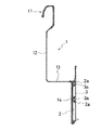
図1はこの発明に係る引き出しの前板Fの側面図であり、前板本体1と、前板本体1の背面にポケットを構成するためのセンターパネル2、バックパネル3(図2参照)及び側端に被せるサイドキャップ4とからなるものである。
【0008】
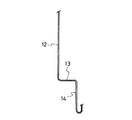
前板本体1は、ステンレス鋼板をプレス曲げ加工して形成するもので、基本的には、把手11を形成するため上部をキャビネット側に凹ませかつほぼ逆J字状に形成し、次いで垂直な上前板12を経て水平な段部13に繋げ、段部13を介してキャビネット側に凹ませるようにして床面に近い下前板14に繋げこれを蹴込としてなるようにしたもので、把手11を予めあだ折して二重とすると共に折曲基部すなわち把手11の先端を筒状に形成したものである。
【0009】
前板本体1の基本的形状は従来例として示したものとほぼ同一であるが、図3に示すような長方形のステンレス鋼板などの肉薄鋼板をプレス曲げ加工にて構成するものである。
図3において長手方向の側端より設けた切欠a、切欠aはあだ折、すなわち180度折り曲げるので外側に向かってはみ出してくる素材のため予め切欠しておくと共に折り曲げ箇所を明示することになる。bは側端に予め貼付する両面テープ等の接着剤である。
【0010】
図4以下は折り曲げ加工工程の概略を示すものである。
図4では、切欠a、切欠aの延長線を折り曲げ基部として図示しないポンチとダイスでV字曲げをする。
図5はあだ折り、すなわち180度曲げて二重にした様子を示す。この時点ではいまだ二重にした把手11となる箇所は密着して添うようにはなっていない。
図6は、折曲基部に丸棒を挟み込み把手11部分を密着させるようにする。
丸棒を挟み込んだ箇所は把手11の先端となり、接着剤bにより端縁は接着されスプリングバックが起きないことになる。
図7は、把手11の指先が触れる箇所をアール型により湾曲させるようにするものである。
図8は、把手11の内奥を直角に折り曲げる様子を示す。
図9は、逆J型となるようほぼ45度把手11先端側におり返す様子を示す。
図10は把手11から上前板12に至る箇所を折り曲げる様子である。このように折り返し部分を斜面に至るまでとすることで、はがれにくくなり、かつ強度が増し、さらには使用に際して引き出しを出して上から見たときにも柄や模様が表れ、しかも柄のない裏面が目につかなくなるのである。
図11は、下前板14の下端を背面側に折り曲げる様子を示すものである。これは曲げられた端が上型か下型につき当たって加工できなくなることを防ぐため先になしたものである。
図12は、下前板14の上端部を区画するように直角に折り曲げる状態を表わすものである。
図13は、水平な段部13と上前板の間を直角に折り曲げる状態を示す。
【0011】
上述のプレス曲げ加工は、最初に把手11のあだ折りをなせば、その他の順序は適宜変更することができる。
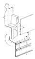
このようにして得る前板本体1の下前板14の背面の全長に渡ってセンターパネル2を両面テープなどの接着剤にて貼り付け、このセンターパネル2の二つの蟻溝状突起2aには若干短いバックパネル3の突起3aをスライドさせて嵌め込み(図2、図16参照)その上部が上前板12と対向するようにする。これらのセンターパネル2及びバックパネル3はアルミニウムの押出成形品から形成してある。これらは内部にあって常態では目に触れないからである。
最後にプラスチックの成形品からなるサイドキャップ4を両側端に被せると共にバックパネル3の側端に当接させる。このとき、前板本体1把手11の上端面の端に丸穴11aを穿ち、ここに嵌り込む突起4aをサイドキャップ4の内側に設けて外れ難くしてある。また、サイドキャップ4の下方では、その背面でセンターパネル2の蟻溝状突起2a内にナット5を内装しサイドキャップ4の背面の穴4bからビス6、6をねじ込むことで止めるようにする。
【0012】
【発明の効果】
請求項1の発明では、引き出しの前板本体を、蹴込となる下前板より水平な段部を経て上前板から指先が下から入るほぼ逆J字状の把手に至る全体としてほぼZ形の前板を肉薄鋼板を折り曲げて形成するに当たり、把手を予めあだ折して二重としたので、剛性が増しつかみ易くなったのである。
また、把手の先端の折曲基部が筒状となったので指先が掛かり確実に引き出せることになる。
把手の部分を予めあだ折したので、ステンレス鋼板等の片面にエンボス、コイニング、着色等で模様などを付しても、使用状態における前面に全て表れることになるのである。
【図面の簡単な説明】
【図1】この発明に係る厨房家具用キャビネットの引き出しの側面図である。
【図2】図1の縦端面図である。
【図3】引き出しの前板本体の素材を示す平面図である。
【図4】引き出しの前板本体を折曲形成する場合の加工工程1を示す。
【図5】引き出しの前板本体を折曲形成する場合の加工工程2を示す。
【図6】引き出しの前板本体を折曲形成する場合の加工工程3を示す。
【図7】引き出しの前板本体を折曲形成する場合の加工工程4を示す。
【図8】引き出しの前板本体を折曲形成する場合の加工工程5を示す。
【図9】引き出しの前板本体を折曲形成する場合の加工工程6を示す。
【図10】引き出しの前板本体を折曲形成する場合の加工工程7を示す。
【図11】引き出しの前板本体を折曲形成する場合の加工工程8を示す。
【図12】引き出しの前板本体を折曲形成する場合の加工工程9を示す。
【図13】引き出しの前板本体を折曲形成する場合の加工工程10を示す。
【図14】この発明に係る引き出しの前板とサイドキャップとの斜視図である。
【図15】この発明に係る引き出しの前板の正面図である。
【図16】引き出しの前板の分解斜視図である。
【図17】従来例の厨房家具キャビネットの斜視図である。
【図18】同じく従来例の厨房家具キャビネットの斜視図である。
【図19】従来の引き出しの斜視図である。
【図20】従来の引き出しの使用状態の断面図である。
【符号の説明】
F 前板
1 前板本体
2 センターパネル
3 バックパネル
4 サイドキャップ[0001]
BACKGROUND OF THE INVENTION
The present invention relates to a drawer front plate body used as the lowest stage of a cabinet for kitchen furniture such as a sink as a component of a system kitchen, a sink, a sink as a single unit, and a stove.
[0002]
[Prior art]
The applicant intends to increase the storage capacity of the base cabinet by eliminating the pedestal that was a dead space from the base cabinet of the conventional system kitchen etc., and at the same time, large kitchen utensils, cooking utensils and small containers etc. We thought about improving the usability by separating and storing. Specifically, a plurality of drawers are arranged at the bottom of the front surface of the box body whose front surface is opened by the bottom plate, the left and right side plates, the back plate and the top plate, and the front plate of this drawer is the bottom plate of the box body. Invented a kitchen furniture cabinet (see FIG. 17 and FIG. 18) characterized in that a close portion was recessed and made into a kick, and filed as Japanese Patent Application No. 11-38099, No. 11-14921, etc. Actually commercialized.
19 and 20, the lowermost drawer front plate F was created during the application and commercialization, but the
[0003]
A
Since the
The height of the
[0004]
[Problems to be solved by the invention]
The main body of the front plate F of the lowermost drawer in the previous invention and design is an aluminum extrusion-molded product in consideration of formability and manufacturing cost, but a stainless steel plate is used as a material for the table top, cabinet body and door. In the case of things, there was a problem that the uniformity of the design as a whole was impaired by the appearance of metals with different textures that were common in the case of being made of metal.
[0005]
Therefore, it is conceivable to form the main body of the front plate F having the same shape as before by using a thin steel plate such as a stainless steel plate as a raw material instead of an aluminum extrusion-molded product, and by press bending. And I thought about adopting a pattern or pattern with embossing, coining, coloring, etc. on the front face that I could see most. However, because the handle has an inverted J shape, the back side becomes the front, I faced the problem that the back side with no pattern appeared. Of course, attaching a pattern or pattern to the front and back is not a good measure because it raises the manufacturing cost, and if it is made of thin steel plate, it may be injured if the edge of the handle touched by the hand is not processed, and it is not safe. There was also a problem.
Furthermore, thin steel plates are not stiff with respect to load, and in particular, if they are wide front plates, bending occurs when gripping and pulling them out, making it difficult to grasp, and reducing and reinforcing the amount of bending is necessary.
[0006]
[Means for Solving the Problems]
Accordingly, in the present invention, the substantially Z-shaped front plate body as a whole extends from the upper front plate to the almost inverted J-shaped handle through which the fingertip enters from below through the horizontal stepped portion from the lower front plate to be kicked. Is formed by bending the handle in advance to make it double, and the bent base, that is, the tip of the handle is formed into a cylindrical shape.
[0007]
DETAILED DESCRIPTION OF THE INVENTION
The drawer
FIG. 1 is a side view of a front plate F of a drawer according to the present invention, and includes a
[0008]
The
[0009]
The basic shape of the
In FIG. 3, the notch a and the notch a provided from the side edges in the longitudinal direction are folds, that is, bent 180 degrees, so that they are notched in advance because the material protrudes toward the outside, and the bent portion is clearly indicated. . b is an adhesive such as a double-sided tape that is applied to the side end in advance.
[0010]
FIG. 4 and subsequent figures show an outline of the bending process.
In FIG. 4, V-bending is performed with a punch and a die (not shown) using a notch a and an extension line of the notch a as a bending base.
FIG. 5 shows a state where the fold is made, that is, it is bent 180 degrees to be doubled. At this point, the portion that becomes the
In FIG. 6, a round bar is sandwiched between the bent bases so that the
The portion where the round bar is sandwiched becomes the tip of the
In FIG. 7, a portion touched by the fingertip of the
FIG. 8 shows a state in which the inner depth of the
FIG. 9 shows a state of returning to the front end side of the
FIG. 10 shows a state where a portion from the
FIG. 11 shows a state in which the lower end of the
FIG. 12 shows a state where the
FIG. 13 shows a state where the
[0011]
In the above-described press bending process, if the
The
Finally, a
[0012]
【The invention's effect】
In the first aspect of the invention, the front plate body of the drawer is substantially Z-shaped as a whole from the upper front plate to the substantially inverted J-shaped handle from which the fingertip enters from below through the step parallel to the lower front plate to be kicked. When the front plate was formed by bending a thin steel plate, the handle was previously folded and doubled, so that the rigidity increased and it became easier to grasp.
In addition, since the bent base at the tip of the handle has a cylindrical shape, the fingertip is hooked and can be reliably pulled out.
Since the handle portion has been folded in advance, even if a pattern such as embossing, coining, coloring, etc. is applied to one side of a stainless steel plate or the like, it will appear entirely on the front surface in use.
[Brief description of the drawings]
FIG. 1 is a side view of a drawer of a kitchen furniture cabinet according to the present invention.
2 is a vertical end view of FIG. 1. FIG.
FIG. 3 is a plan view showing a material of a drawer front plate body.
FIG. 4 shows a
FIG. 5 shows a
FIG. 6 shows a
FIG. 7 shows a
FIG. 8 shows a
FIG. 9 shows a processing step 6 in the case of bending a drawer front plate body.
FIG. 10 shows a
FIG. 11 shows a processing step 8 in the case of bending the drawer front plate body.
FIG. 12 shows a processing step 9 in the case of bending the drawer front plate body.
FIG. 13 shows a processing step 10 in the case of bending a drawer front plate body.
FIG. 14 is a perspective view of the drawer front plate and the side cap according to the present invention.
FIG. 15 is a front view of the front plate of the drawer according to the present invention.
FIG. 16 is an exploded perspective view of the front plate of the drawer.
FIG. 17 is a perspective view of a conventional kitchen furniture cabinet.
FIG. 18 is a perspective view of a conventional kitchen furniture cabinet.
FIG. 19 is a perspective view of a conventional drawer.
FIG. 20 is a cross-sectional view of a conventional drawer in use.
[Explanation of symbols]
Claims (1)
Priority Applications (1)
| Application Number | Priority Date | Filing Date | Title |
|---|---|---|---|
| JP2000029974A JP4262855B2 (en) | 2000-02-08 | 2000-02-08 | Drawer front panel for kitchen furniture |
Applications Claiming Priority (1)
| Application Number | Priority Date | Filing Date | Title |
|---|---|---|---|
| JP2000029974A JP4262855B2 (en) | 2000-02-08 | 2000-02-08 | Drawer front panel for kitchen furniture |
Publications (3)
| Publication Number | Publication Date |
|---|---|
| JP2001218642A JP2001218642A (en) | 2001-08-14 |
| JP2001218642A5 JP2001218642A5 (en) | 2007-03-22 |
| JP4262855B2 true JP4262855B2 (en) | 2009-05-13 |
Family
ID=18555050
Family Applications (1)
| Application Number | Title | Priority Date | Filing Date |
|---|---|---|---|
| JP2000029974A Expired - Fee Related JP4262855B2 (en) | 2000-02-08 | 2000-02-08 | Drawer front panel for kitchen furniture |
Country Status (1)
| Country | Link |
|---|---|
| JP (1) | JP4262855B2 (en) |
Families Citing this family (4)
| Publication number | Priority date | Publication date | Assignee | Title |
|---|---|---|---|---|
| JP4617961B2 (en) * | 2005-03-30 | 2011-01-26 | パナソニック電工株式会社 | Kitchen equipment |
| JP5831515B2 (en) * | 2013-09-10 | 2015-12-09 | 三菱電機株式会社 | Refrigerator door panel and refrigerator provided with the refrigerator door panel |
| JP6230391B2 (en) * | 2013-11-29 | 2017-11-15 | 株式会社Lixil | Kicking drawer connecting member and kicking drawer |
| JP7122036B1 (en) | 2021-05-19 | 2022-08-19 | 株式会社飯塚鉄工所 | DOOR DEVICE AND METHOD OF MANUFACTURING DOOR DEVICE |
-
2000
- 2000-02-08 JP JP2000029974A patent/JP4262855B2/en not_active Expired - Fee Related
Also Published As
| Publication number | Publication date |
|---|---|
| JP2001218642A (en) | 2001-08-14 |
Similar Documents
| Publication | Publication Date | Title |
|---|---|---|
| USD911782S1 (en) | Expandable spice rack | |
| USD470632S1 (en) | Washing machine | |
| USD525790S1 (en) | Under furniture storage unit | |
| US5871107A (en) | Versatile spice keeper | |
| USD496805S1 (en) | Two drawer base cabinet | |
| USD428415S (en) | Operation controller with a display for electronic computers | |
| USD494394S1 (en) | Shelf display divider for absorbent articles | |
| USD551007S1 (en) | Bag dispenser rack | |
| USD323251S (en) | Combined desk, wall panel and storage unit | |
| JP4262855B2 (en) | Drawer front panel for kitchen furniture | |
| USD444930S1 (en) | Display and storage case having hinged lid with false drawerfronts | |
| USD452820S1 (en) | Product display tray | |
| USD408169S (en) | Computer cabinet | |
| USD522770S1 (en) | Dresser | |
| USD492200S1 (en) | Spice container with tear strip | |
| USD984825S1 (en) | Bathroom storage cabinet | |
| USD487278S1 (en) | Wine refrigerator | |
| USD468420S1 (en) | Cabinet for medical articles | |
| USD527587S1 (en) | Paper products dispenser | |
| USD477732S1 (en) | Shelf with towel bar | |
| USD451728S1 (en) | Rolled product dispenser | |
| USD1025667S1 (en) | Storage cabinet | |
| USD521372S1 (en) | Container having thumb access door and integrally hinged lid | |
| USD1025670S1 (en) | Storage cabinet | |
| CN213911447U (en) | Embedded sterilizing cabinet |
Legal Events
| Date | Code | Title | Description |
|---|---|---|---|
| A521 | Written amendment |
Free format text: JAPANESE INTERMEDIATE CODE: A523 Effective date: 20070205 |
|
| A621 | Written request for application examination |
Free format text: JAPANESE INTERMEDIATE CODE: A621 Effective date: 20070205 |
|
| A977 | Report on retrieval |
Free format text: JAPANESE INTERMEDIATE CODE: A971007 Effective date: 20090107 |
|
| TRDD | Decision of grant or rejection written | ||
| A01 | Written decision to grant a patent or to grant a registration (utility model) |
Free format text: JAPANESE INTERMEDIATE CODE: A01 Effective date: 20090120 |
|
| A01 | Written decision to grant a patent or to grant a registration (utility model) |
Free format text: JAPANESE INTERMEDIATE CODE: A01 |
|
| A61 | First payment of annual fees (during grant procedure) |
Free format text: JAPANESE INTERMEDIATE CODE: A61 Effective date: 20090210 |
|
| FPAY | Renewal fee payment (event date is renewal date of database) |
Free format text: PAYMENT UNTIL: 20120220 Year of fee payment: 3 |
|
| R150 | Certificate of patent or registration of utility model |
Free format text: JAPANESE INTERMEDIATE CODE: R150 |
|
| LAPS | Cancellation because of no payment of annual fees |