JP4262810B2 - X-ray tube anode rotation drive device - Google Patents
X-ray tube anode rotation drive device Download PDFInfo
- Publication number
- JP4262810B2 JP4262810B2 JP33649698A JP33649698A JP4262810B2 JP 4262810 B2 JP4262810 B2 JP 4262810B2 JP 33649698 A JP33649698 A JP 33649698A JP 33649698 A JP33649698 A JP 33649698A JP 4262810 B2 JP4262810 B2 JP 4262810B2
- Authority
- JP
- Japan
- Prior art keywords
- phase
- output
- anode
- ray tube
- anode rotation
- Prior art date
- Legal status (The legal status is an assumption and is not a legal conclusion. Google has not performed a legal analysis and makes no representation as to the accuracy of the status listed.)
- Expired - Lifetime
Links
Images


Landscapes
- X-Ray Techniques (AREA)
Description
【0001】
【発明の属する技術分野】
本発明は、X線装置及びX線CT装置に用いられるX線管の陽極回転駆動装置に係り、特に3相式の陽極回転機構を有するX線管にも2相式の陽極回転機構を有するX線管にも用いることができるX線管の陽極回転駆動装置に関する。
【0002】
【従来の技術】
電子衝撃面を移動して許容負荷を増大させる回転陽極X線管は、現在はX線装置及びX線CT装置の分野で非常に多く用いられている。
【0003】
このようなX線管の陽極は、回転子と傘状のターゲットからなり、誘導モータの原理で回転する。前記ターゲットを回転することによりターゲットの電子衝撃面積は増大し、短時間負荷の場合、焦点の単位面積当たりの入力を非常に大きくすることができるので、大容量のX線管が可能となる。前記X線管の陽極は、X線管球外にある固定子に電流を流して回転磁界を発生させると、X線管球内にある回転子コイルを具備した陽極が回転する。
【0004】
このように、陽極は、上記した誘導モータと同じ原理で回転するが、誘導モータと異なるのは、管球を覆っているガラス、またはメタルが固定子と回転子間に存在し、ギャップが大きいことである。固定子コイルは、単純で安価な2相式が主流であったが、誘導モータと同様、最近では3相式のものが出現している。3相式の陽極回転機構は、高速応答を特徴とし、陽極回転の起動に高速さを要する場合に有利である。
【0005】
図12に従来の3相式の陽極回転機構をもつX線管とその駆動回路を示している。
この図12において、10は直流電源、22〜27は半導体スイッチ(ここでは、絶縁ゲート形バイポーラトランジスタIGBTを使用)で、この6個の半導体スイッチで3相のフルブリッジインバータ回路20を構成する。40はX線管で、3相式の陽極回転機構42を備えており、この3相式の陽極回転機構42に前記3相フルブリッジインバータ回路2から出力される3相の交流電圧が供給される。
【0006】
31は前記フルブリッジインバータ回路を制御する制御回路で、高電圧発生装置(図示省略)から、陽極を高速に回転させるか低速に回転させるかを切り換える高速/低速切り換え信号と、陽極が起動か起動後の定常回転かを切り換える起動/定常切り換え信号と、陽極を停止させるときに制動をかける制動信号と、陽極を駆動させるか停止させるかの駆動/停止切り換え信号とを入力し、これらの入力信号に対応して3相フルブリッジインバータ回路20の各スイッチ22〜27のオン,オフのゲート信号を出力する制御回路である。
【0007】
次に、このように構成された従来の3相陽極回転機構をもつX線管とその駆動回路の動作について説明する。
【0008】
(1)高速/低速切り換え
X線管の陽極を高速で回転させるか低速で回転させるかは、X線管にかかる負荷電力の大きさで決めている。負荷が大きい場合は陽極を高速に回転させ、負荷が小さい場合は低速で回転させる。高速/低速切り換え信号が高速に設定されている場合、3相フルブリッジインバータ回路20は、例えば500V,120Hzの3相交流電圧を出力し、高速/低速切り換え信号が低速に設定されている場合は、3相フルブリッジインバータ回路20は、例えば200V,50Hzの3相交流電圧を出力するように制御回路31より上記3相フルブリッジインバータ回路20の半導体スイッチ22〜27を駆動制御するパルスを出力する。
【0009】
(2)起動/定常切り換え
陽極回転が起動中かまたは設定回転数に達し定常時かを選択する起動/定常切り換え信号が起動に設定されている場合、3相フルブリッジインバータ回路20は、例えば500Vの高電圧(高速回転時)を陽極回転機構42に出力し、定常に設定されている場合は、例えば100Vの低電圧(高速回転時)を陽極回転機構42に出力する。
このように、起動時に高い電圧を出力するのは大きな起動トルクを得るためである。
【0010】
(3)制動信号
X線曝射の終了後に陽極回転を停止させるための制動信号が与えられている場合、3相フルブリッジインバータ回路20は任意の半導体スイッチをオンさせて直流電圧を得て、これを陽極回転機構42に供給して陽極回転機構に直流制動をかける。例えば、前記3相フルブリッジインバータ回路20の半導体スイッチ22と25をオン,オフさせ、このオン,オフの比率を調整して出力電圧を70V程度にして陽極回転機構に直流制動をかけ、停止させる。
【0011】
(4)駆動/停止切り換え
X線撮影をするかしないかによって陽極を回転させるか否かを切り換える駆動/停止切り換え信号が駆動に設定されている場合、3相フルブリッジインバータ回路42は陽極回転機構に3相交流電圧を出力し、停止が設定されている場合は,陽極回転機構に0Vの電圧を出力するか、または電圧を出力しない。
【0012】
以上の高速/低速切り換え信号,起動/定常切り換え信号,制動信号,駆動/停止切り換え信号が制御回路31に入力されると、制御回路31は入力された信号に見合った駆動用3相交流電圧Vu,Vv,Vwを陽極駆動機構42へ供給するために3相フルブリッジインバータ回路20の各スイッチ22〜27のオンオフのゲート信号を出力する。陽極回転機構42に3相交流電圧Vu,Vv,Vwが供給されると,陽極が回転する。
【0013】
3相陽極回転機構には、Δ結線かY結線かの3つの固定子コイルがある。それぞれに120°ずつ位相のずれた交流電圧Vu,Vv,Vwを供給し、固定子コイルに回転磁界が生じて3相誘導モータの原理で陽極が回転する。
図13に、従来の2相陽極回転機構をもつX線管とその駆動回路を示している。
【0014】
上記の3相フルブリッジインバータ回路の代わりに単相フルブリッジインバータ回路21を用い、3相の陽極回転機構の代わりに2相の陽極回転機構43を用いている。4つの信号(高速/低速切り換え信号,起動/定常切り換え信号,制動信号,駆動/停止切り換え信号)を入力する制御回路32は、図12における3相フルブリッジインバータ回路20の制御回路31と同様の動作をし、入力された信号に見合った駆動用2相交流電圧Vmain,Vsub,Vcomを陽極駆動機構43へ供給するために単相フルブリッジインバータ回路21の各スイッチ22’〜25’のオン,オフのゲート信号を出力する。
【0015】
通常、2相陽極回転機構には、コモン端子で直列接続されている主コイルと補助コイルの2つの固定子コイルがある。主コイルの一端に交流電圧Vmain、補助コイルの一端に前記交流電圧の位相を90°シフトさせた電圧Vsub、両コイルのコモン端には前記2つのコモン電圧Vcomを供給することで、固定子コイルに回転磁界が生じ単相誘導モータの原理で陽極が回転する。
【0016】
図21(a)は、位相シフトコンデンサ50を用いた駆動回路とX線管を示している。単相フルブリッジインバータ回路21の2つの出力は、主コイルへVmain,両コイルのコモン端へVcom,補助コイルへのVsubは位相を90°ずらす為にVmainから位相シフトコンデンサ50を介して供給している。
【0017】
図21(b)は、単相フルブリッジインバータ回路21a,21bを2つ用いた駆動回路とX線管を示している。直流電源10に接続された2つの単相フルブリッジインバータ回路21a,21bは、それぞれのインバータ回路の出力に接続された絶縁トランス51a,51bを介して90°位相のずれた交流電圧を2相陽極回転機構43に供給する。絶縁トランス51a,51bは、インバータ回路21a,21bの内部のスイッチが短絡するのを防ぐために用いている。
【0018】
【発明が解決しようとしている課題】
以上、説明したように、陽極回転式のX線管には、3相陽極回転機構のX線管と2相陽極回転機構のX線管があり、これらの陽極回転機構を持つX線管の陽極回転駆動装置には、従来は前記3相陽極回転機構を持つX線管には3相フルブリッジインバータ回路による駆動回路を、2相陽極回転機構を持つX線管には2相フルブリッジインバータ回路による駆動回路又は2つの単相フルブリッジインバータ回路を用いた方式を採用しており、3相陽極回転機構のX線管と2相陽極回転機構のX線管で同じ陽極駆動回路を用いることができなかった。すなわち、図12の回路構成は3相の陽極回転機構のみの対応で,2相の陽極回転機構を駆動できない。X線CT装置のように撮影回数が多く寿命の短いX線管は、取り替えが頻繁である。取り替えの際、2相陽極回転機構をもつX線管から容量の大きい3相陽極回転機構をもつX線管へ変更したいといった場合には、駆動回路も変更する必要がある。つまり、従来の駆動回路は汎用性に乏しい。
【0019】
また、図21(a)の回路構成では、陽極回転機構の固定子コイルと直列接続されたコンデンサ23とで確実に位相を90°シフトさせるのは難しく、陽極回転に十分なトルクが得られない。図21(b)の回路構成では、絶縁トランス,インバータ回路が2組ずつあることから装置容積,重量が大きくなってしまう。また、半導体スイッチが短絡するのを防ぐ手段として、絶縁トランスを単相インバータ回路の出力段に設けるのではなく、入力電源を各々に分離して供給する方法も考えられる。しかし、この方法では入力段に2つの直流電圧源として、絶縁トランス,整流回路,平滑コンデンサを2組ずつ要し、図21(b)の構成より更に装置容積,重量が大きくなってしまう。
【0020】
このように、従来方式では、3相と2相の陽極回転機構を持つX線管の陽極回転駆動装置には異なる構成の回路を用いていたために汎用性に乏しく、また2相陽極回転機構の駆動回路は十分なトルクが得られず、装置容積が大きい,重量が大きいといった問題点があった。
【0021】
そこで、本発明の目的は、上記の従来装置の問題点を解決し、X線管陽極回転機構の固定子コイルの相数が2相や3相に関わらず、同一の駆動回路構成で陽極回転が可能となり、小型軽量のX線管の陽極回転駆動装置を提供することにある。
【0022】
【課題を解決するための手段】
上記目的は、3相陽極回転機構を持つX線管の前記陽極回転機構には3相交流電圧を、2相陽極回転機構を持つX線管の前記陽極回転機構には2相交流電圧を供給して前記3相陽極回転機構を持つX線管及び2相陽極回転機構を持つX線管の陽極を回転させるX線管の陽極回転駆動装置において、直流電源と、この直流電源を3相若しくは2相の交流電圧に変換するインバータ回路と、このインバータ回路を構成する複数のスイッチング素子をオン,オフ制御して前記3相若しくは2相の交流電圧を発生するための3相交流信号若しくは2相交流信号を生成するベクトル変換手段と、このベクトル変換手段より発生する信号を3相交流信号にするか2相交流信号にするかを選択する3相/2相選択手段とを備え、この選択手段の切り換えにより前記X線管が3相陽極回転機構を持つ場合は前記ベクトル変換手段から3相交流信号を出力し、この信号で前記インバータ回路より3相交流電圧を発生してこれを前記3相陽極回転機構を持つX線管の陽極回転機構に供給し、前記X線管が2相陽極回転機構を持つ場合は前記ベクトル変換手段から2相交流信号を出力し、この信号で前記インバータ回路より2相交流電圧を発生してこれを2相陽極回転機構を持つX線管の陽極回転機構に供給することによって達成される。
【0023】
このように構成することによって、X線管の陽極回転機構が3相式の場合は、3相/2相選択手段で3相を選択してベクトル変換手段から3相交流信号を生成し、この信号に基づいて3相インバータ回路から3相交流電圧を発生して前記3相陽極回転機構を持つX線管の陽極を回転させ、X線管の陽極回転機構が2相式の場合は、3相/2相選択手段で2相を選択してベクトル変換手段から2相交流信号を生成し、この信号に基づいて前記3相インバータ回路の任意のスイッチング素子をオン、オフして2相交流電圧を発生し前記2相陽極回転機構を持つX線管の陽極を回転させる。
【0024】
また、上記ヘクトル変換手段から出力される交流信号は、X線管の陽極回転機構が3相式の場合は位相が120°ずれた3相交流信号を、X線管の陽極回転機構が2相式の場合は位相が90°ずれた2相交流信号を生成し、これらの信号に基づいてインバータ回路からX線管の陽極回転機構が3相式の場合は位相が120°ずれた3相交流電圧を、X線管の陽極回転機構が2相式の場合は位相が90°ずれた2相交流電圧を発生して前記X線管の陽極を回転させる。このように、3相/2相選択手段,ベクトル変換手段,インバータ回路を備えることによって、3相陽極回転機構を持つX線管と2相陽極回転機構を持つX線管で同一の陽極回転駆動装置が構成できる。
【0025】
【発明の実施の形態】
図1は本発明によるX線管の陽極回転駆動装置の実施例を示す図である。
直流電源10と、3相フルブリッジインバータ回路20と、制御回路30により構成される。X線管40の陽極回転機構が3相陽極回転機構42の場合には、3相フルブリッジインバータ回路20から出力される、位相が120°ずれた3相の交流電圧を前記3相陽極回転機構42に供給し、X線管41の陽極回転機構が2相陽極回転機構43の場合には、3相フルブリッジインバータ回路20から出力される、位相が90°ずれた2相の交流電圧を前記2相陽極回転機構43に供給する。
【0026】
3相フルブリッジインバータ回路20は、6個の半導体スイッチ22〜27で構成される。
【0027】
制御回路30は、高電圧発生装置(図示省略)から陽極回転の高速/低速切り換え信号と、起動/定常切り換え信号と、制動信号と、駆動/停止切り換え信号とを入力し、これらの信号に対応した前記3相及び2相の陽極回転機構に供給する交流電圧のゲインを決めるゲイン決定器33と、このゲイン決定器33より出力されるゲインで前記高電圧発生装置からの陽極回転の高速/低速切り換え信号に対応した正弦波電圧を発生させる正弦波発生器34と、前記ゲイン決定器33より出力されるゲインで直流電圧を発生させる直流発生器35と、前記高電圧発生装置から制動信号を入力して前記正弦波電圧あるいは直流電圧のいずれかを出力するための切り換え手段36と、この切り換え手段36から出力された電圧と前記高電圧発生装置から3相/2相切り換え信号を入力し3相あるいは2相の交流電圧を生成するベクトル変換器37と、このベクトル変換器37の出力と前記高電圧発生装置から駆動/停止信号を入力し前記3相フルブリッジインバータ回路20の各半導体スイッチ22〜27のオン,オフのゲート信号を出力するパルス幅変調(PWM)信号発生器38とから構成される。次に、このように構成された本発明のX線管の陽極回転駆動装置の動作について説明する。3相陽極回転機構42には、Δ結線かY結線かの3つの固定子コイルがある。それぞれの固定子コイルに120°ずつ位相のずれた交流電圧Vu,Vv,Vwを供給すると、固定子コイルには3相交流電流が流れ、これによって回転磁界が生じて3相誘導モータの原理で陽極は回転する。
【0028】
X線管にかかる負荷電力の大きさに合わせて陽極の回転速度を選択する高速/低速切り換え信号は、X線管にかかる負荷電力が大きいときは高速に設定され、3相フルブリッジインバータ回路20は、例えば500V,120Hzの3相交流電圧を3相陽極回転機構42に出力する。一方、X線管にかかる負荷電力が小さいときは、前記信号は低速に設定され、3相フルブリッジインバータ回路20は、例えば200V,50Hzの3相交流電圧を3相陽極回転機構42に出力する。また、陽極回転が起動中かまたは前記3相交流電圧の周波数で決まる設定回転数である定常回転数に達したかを選択する起動/定常切り換え信号が起動側に設定されている場合、3相フルブリッジインバータ回路20は、例えば500V,120Hzの3相交流電圧を3相陽極回転機構42に出力し、定常に設定されている場合、3相フルブリッジインバータ回路20は、例えば100V,120Hzの3相交流電圧を3相陽極回転機構42に出力する。
【0029】
X線曝射終了後に陽極回転を停止させるために制動信号が与えられた場合、3相フルブリッジインバータ回路20は任意の半導体スイッチをオンさせて、例えば70V程度の直流電圧を得て、これを陽極回転機構42に供給して陽極回転機構に直流制動をかける。例えば、前記3相フルブリッジインバータ回路20の半導体スイッチ22と25をオン,オフさせ、このオン,オフの比率を調整して70V程度の直流出力電圧を得て、これを陽極回転機構の固定子巻線の任意の端子に入力して直流制動をかけ、停止させる。
【0030】
次に、X線撮影をするかしないかによって陽極回転の駆動,停止を切り換える駆動/停止切り換え信号が駆動に設定されている場合、3相フルブリッジインバータ回路20は、陽極回転機構に3相交流電圧を出力し、停止が設定されている場合は、3相フルブリッジインバータ回路20は陽極回転機構に0Vの電圧を出力するか、または電圧を出力しない。3相あるいは2相の陽極回転機構を選択する3相/2相切り換え信号は、この場合、3相陽極回転機構を持つX線管を用いているので3相に設定されており、3相フルブリッジインバータ回路20は位相が120°ずれた3相交流電圧を陽極回転機構に供給する。
【0031】
上記の制御回路30は、その内部構成のうちゲイン決定器33,正弦波発生器34,直流発生器35,切り換え手段36,ベクトル変換器37の部分をマイクロコンピュータで構成し、これらの構成要素の各処理はソフトウェアで行う。
【0032】
図2は前記制御回路30内のマイクロコンピュータ部である。入出力インターフェイス回路I/Oを介して高速/低速切り換え信号,起動/定常切り換え信号,制動信号,駆動/停止切り換え信号,3φ/2φ切り換え信号の各信号を入力し、これらの信号に対応した3相フルブリッジインバータ回路20の半導体スイッチ22〜27を駆動するパルス幅変調(PWM)信号を中央処理装置CPUで演算して前記I/Oから出力する。これらのPWM信号は、アナログ回路で構成されたPWM発生器38(図1)の入力となる。PWM発生器38は、陽極回転機構の駆動時に駆動/停止切り換え信号が駆動側に選択されており、ベクトル変換器37の出力信号に見合った3相フルブリッジインバータ回路20の各半導体スイッチ22〜27のオン,オフのゲート信号を出力する。一方、陽極回転機構の停止時には、駆動/停止切り換え信号が停止側に選択されており、ゲート信号を出力しない。
【0033】
このように3相陽極回転機構42に3相交流電圧Vu,Vv,Vwが供給されると陽極が回転する。
【0034】
図3は、ゲイン決定器33の詳細を示したものである。ゲイン決定器33は、高速/低速切り換え信号,起動/定常切り換え信号,制動信号,駆動/停止切り換え信号を入力信号とし、それらの信号に見合った駆動用3相交流電圧Vu,Vv,Vw及び制動用直流電圧を陽極回転駆動機構42へ供給するためのゲインを決定する。そして、決定されたゲインを正弦波発生器34と直流発生器35に出力する。
【0035】
図4は、正弦波発生器34の詳細を示したものである。正弦波発生器34は、前記高速/低速切り換え信号に見合った周波数をもち、ゲイン決定器33から得たゲインに見合った電圧値の3相正弦波電圧を発生する。
【0036】
ピーク値が1の正弦波データをテーブル化しておき、これを図2のメモリに記憶しておく。高速/低速切り換え信号が高速の場合は前記メモリから高速に見合った正弦波データを読み出し、前記高速/低速切り換え信号が低速の場合は前記メモリから低速に見合った正弦波データを読み出し、これらをゲイン決定器からの出力に対応した値に増幅器Ampで増幅して3相の正弦波交流電圧を出力する。
【0037】
図5は、直流発生器35の詳細を示したものである。直流発生器35は、基準値1をゲイン決定器33から得たゲインに見合った値に増幅器Ampで増幅して直流電圧を発生する。
【0038】
図1の切り換え手段36は、正弦波発生器34から発生した3相正弦波電圧と直流発生器35から発生した直流電圧とが入力される。制動信号の有無により陽極回転の起動中または定常時には3相正弦波電圧を、X線曝射終了後の陽極回転の制動時には直流電圧をベクトル変換器37へ出力する。
【0039】
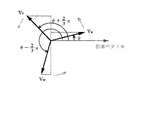
図6はベクトル変換器37の詳細を示したものである。ベクトル変換器37は、3相あるいは2相の陽極回転機構を選択する3相/2相切り換え信号により、3相が選択されている場合は120°位相のずれた3相信号をPWM発生器38へ出力し、2相が選択されている場合は90°位相のずれた2相信号をPWM発生器38へ出力する。図7は、3相の陽極回転機構を用いた場合のベクトル変換器37の出力ベクトルを示している。ベクトル図は、経過時間で変化する正弦波のような関数を扱うときに有利な方法である。陽極駆動時において3相が選択された3相/2相切り換え信号が入力されると、ベクトル変換器37は切り換え手段36から入力された周波数,振幅をもった電圧信号を3相に変換して出力する。
【0040】
出力される3相正弦波電圧Vu,Vv,Vwは時間の経過と共に位相が変化し、図7のベクトル図における3本のベクトルは120°の位相差を保ちながら反時計方向に回転することになる。3相正弦波電圧Vu,Vv,Vwのスカラ量を次式に示す(最大値をVとする)。
【数1】

【0041】
次に、2相回転陽極機構を持つX線管の本発明の陽極回転駆動装置の動作について説明する。
通常、2相陽極回転機構には、コモン端子で直列接続されている主コイルと補助コイルの2つの固定子コイルがある。主コイルの一端に交流電圧Vmain,補助コイルの一端には前記交流電圧Vmainから位相を90°シフトさせた電圧Vsub,両コイルのコモン端には前記2つのコモン電圧Vcomを供給することで、固定子コイルに回転磁界が生じ単相誘導モータの原理で陽極が回転する。
【0042】
高速/低速切り換え信号と、起動/定常切り換え信号と、制動信号と、駆動/停止切り換え信号とが制御回路30のゲイン決定器33に入力される。ゲイン決定器33は入力された信号に見合った駆動用2相交流電圧Vmain,Vsub,Vcomを陽極駆動機構43へ供給するための前記2相交流電圧のゲインを決定する。陽極回転の起動中または定常回転時に3相正弦波電圧が入力されるベクトル変換器37は、2相が選択されている3相/2相切り換え信号によって、3相の電圧を2相に変換しPWM発生器38へ出力する。このように制御回路30は陽極駆動時において3相フルブリッジインバータ回路20の各スイッチ22〜27のオン,オフのゲート信号を出力し、2相陽極回転機構43に2相交流電圧Vmain,Vsub,Vcomが供給されて陽極が回転する。
【0043】
制御回路30において、3相の陽極回転機構を駆動する場合と異なるのは、ベクトル変換器37の動作である。陽極回転駆動時において、2相が選択された3相/2相切り換え信号が入力されると、ベクトル変換器37は切り換え手段36から入力された周波数,振幅をもった電圧信号を2相に変換し出力する。図6は、ベクトル変換器37の詳細を示している。
【0044】
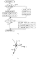
3相/2相切り換え信号が2相に選択された場合、切り換え手段36から入力された電圧信号は前段の3φ(3相)生成器で3相ベクトルに変換されて3相正弦波電圧Vu,Vv,Vwを出力した後、2φ生成器で2相ベクトルに変換しVmain,Vsub、Vcomを出力する。図8は、図6のベクトル変換器をマイクロコンピュータを用いて構成し、前記3相正弦波電圧Vu,Vv,Vw及び2相交流電圧Vmain,Vsub、Vcomをソフトウェアで作成する処理フローチャートの第一の実施例と3相正弦波電圧Vu,Vv,Vwと2相交流電圧Vmain,Vsub,Vcomのベクトル図を示す。
【0045】
下記の(4)〜(6)の式に示すように基準電位Vcomは基準ベクトルの原点に不動で、VuからVmain,VvとVwからVsubを生成する。
【数4】
【0046】
図9は,図6のベクトル変換器をマイクロコンピュータを用いて構成し、前記3相正弦波電圧Vu,Vv,Vw及び2相交流電圧Vmain,Vsub,Vcomをソフトウェアで作成する処理フローチャートの第二の実施例と3相正弦波電圧Vu,Vv,Vwと2相交流電圧Vmain,Vsub,Vcomのベクトル図を示す。
【0047】
この第二の実施例では、基準電位Vcomが変動し、VvからVcom,VuとVcomからVmain,VwとVcomからVsubを生成する。(7)〜(9)式は上記第二の実施例の変換式である。
【数7】
【0048】
図10は、図6のベクトル変換器をマイクロコンピュータを用いて構成し、前記3相正弦波電圧Vu,Vv,Vw及び2相交流電圧Vmain,Vsub,Vcomをソフトウェアで作成する処理フローチャートの第三の実施例と3相正弦波電圧Vu,Vv,Vwと2相交流電圧Vmain,Vsub,Vcomのベクトル図を示す。
【0049】
この第三の実施例は、上記第二の実施例と同様に基準電位Vcomが変動し、VvからVcom,VuとVcomからVmain,VwとVcomからVsubを生成する方法であるが、2相用に3相ベクトルVu,Vv,Vwの位相を120°からずらすために、前記Vu,Vv,Vwの3つのベクトルを2回生成する。上記第一,第二の実施例よりも計算は複雑になるが、VmainとVsubを最も大きく発生できる。
【0050】
図11は、図6のベクトル変換器をマイクロコンピュータを用いて構成し、前記3相正弦波電圧Vu,Vv,Vw及び2相交流電圧Vmain,Vsub,Vcomをソフトウェアで作成する処理フローチャートの第三の実施例と3相正弦波電圧Vu,Vv,Vwと2相交流電圧Vmain,Vsub,Vcomのベクトル図を示す。
【0051】
この第四の実施例の特徴は、上記第一,第二,第三の実施例に比べてVmainかVsubのうちの一方の電圧をより大きく発生できることにある。これは、メインとサブコイルの定格電圧が違うときに有効である。
これらの実施例に基づいてベクトル変換器37が構成されることで、制御回路30からゲート信号が与えられた3相フルブリッジインバータ回路20は、2相交流電圧を陽極回転機構43に出力できる。
【0052】
以上の実施例において,下記のように変形することもできる。
(1)図1の3相フルブリッジインバータ回路20の半導体スイッチ22〜27にはIGBTを使用して説明したが、これはサイリスタやバイポーラトランジスタ,ゲートターンオフサイリスタを初めどのようなスイッチでも構わない。
【0053】
(2)図1の実施例の制御回路30はハードウェアとソフトウェアを組み合わせた構成としたが、これはマイクロコンピュータを用いたソフトウェアのみの構成、またはハードウェアのみの構成としても構わない。
【0054】
(3)図1の実施例の高速/低速切り換え信号,起動/定常切り換え信号は、この2つの信号の組み合わせに限らず、固定子の電圧,周波数を決定する信号であれば良い。
【0055】
(4)図1の実施例の制動信号は、陽極回転機構のベアリングの摩耗を軽減する為に前記陽極回転機構に直流制動をかけるために必要な信号である。このような強制的な制動をかける必要がない場合はなくてもよい。
【0056】
(5)図1の実施例に示した34の正弦波発生器は正弦波に関わらず、矩形波,三角波を初めどのような交流波形を出力する発生器でも構わない。
【0057】
(6)図1の実施例に示した37のベクトル変換器での2相ベクトルの生成は、上記した実施例のみならず、交流電圧Vmain、この交流電圧Vmainの位相を90°シフトさせた電圧Vsub、これらのVmainとVsubの2つのコモン電圧Vcomを生成できるどのような方法でも構わない。
【0058】
以上のように、本発明の主旨は、X線管の陽極回転機構の固定子コイルの相数が2相や3相に関わらず、同一の回路構成で陽極の回転駆動を可能にするものである。
【0059】
【発明の効果】
以上に説明したように、本発明装置では、制御回路に備わったベクトル変換器により、3相フルブリッジインバータ回路から3相交流電圧又は2相交流電圧のいずれかを出力し、これを3相陽極回転機構を持つX線管と2相陽極回転機構を持つX線管のいずれにも供給できるように構成したので、X線管の陽極回転駆動装置を3相陽極回転機構を持つX線管と2相陽極回転機構を持つX線管の両方に共用できるという効果がある。
【図面の簡単な説明】
【図1】本発明によるX線管の陽極回転駆動装置の実施例を示す図である。
【図2】図1の制御回路30内のマイクロコンピュータ部である。
【図3】ゲイン決定器の詳細図である。
【図4】正弦波発生器の詳細図である。
【図5】直流発生器の詳細図である。
【図6】ベクトル変換器の詳細図である。
【図7】3相の電圧ベクトル図である。
【図8】2相ベクトル形成の第一の実施例を示す図である。
【図9】2相ベクトル形成の第二の実施例を示す図である。
【図10】2相ベクトル形成の第三の実施例を示す図である。
【図11】2相ベクトル形成の第四の実施例を示す図である。
【図12】3相陽極回転機構をもつ従来のX線管の陽極回転駆動装置である。
【図13】2相陽極回転機構をもつ従来のX線管の陽極回転駆動装置である。
【符号の説明】
10 直流電源
20 3相フルブリッジインバータ回路
21 単相フルブリッジインバータ回路
22〜27 半導体スイッチ
30 制御回路
33 ゲイン決定器
34 正弦波発生器
35 直流発生器
36 交流/直流切り換え手段
37 ベクトル変換器
38 PWM発生器
40,41 X線管
42 3相陽極回転機構
43 2相陽極回転機構
50 位相シフトコンデンサ[0001]
BACKGROUND OF THE INVENTION
The present invention relates to an X-ray tube anode rotation driving device used in an X-ray apparatus and an X-ray CT apparatus, and more particularly, an X-ray tube having a three-phase anode rotation mechanism also has a two-phase anode rotation mechanism. The present invention relates to an anode rotation driving device for an X-ray tube that can also be used for an X-ray tube.
[0002]
[Prior art]
Rotating anode X-ray tubes that move the electron impact surface to increase the allowable load are currently very popular in the field of X-ray devices and X-ray CT devices.
[0003]
The anode of such an X-ray tube consists of a rotor and an umbrella-shaped target and rotates on the principle of an induction motor. By rotating the target, the electron impact area of the target is increased, and when the load is applied for a short time, the input per unit area of the focal point can be greatly increased, so that a large capacity X-ray tube can be realized. When an electric current is passed through a stator outside the X-ray tube to generate a rotating magnetic field, the anode having the rotor coil in the X-ray tube rotates.
[0004]
In this way, the anode rotates on the same principle as the induction motor described above, but the difference from the induction motor is that glass or metal covering the tube exists between the stator and the rotor, and the gap is large. That is. As the stator coil, a simple and inexpensive two-phase type has been mainstream, but recently, a three-phase type has appeared as well as an induction motor. The three-phase type anode rotation mechanism is characterized by high-speed response, and is advantageous when high speed is required to start anode rotation.
[0005]
FIG. 12 shows a conventional X-ray tube having a three-phase anode rotating mechanism and its driving circuit.
In FIG. 12, 10 is a DC power source, 22 to 27 are semiconductor switches (here, insulated gate bipolar transistors IGBTs are used), and these six semiconductor switches constitute a three-phase full-
[0006]
31 is a control circuit for controlling the full-bridge inverter circuit, from a high voltage generator (not shown), a high-speed / low-speed switching signal for switching whether the anode is rotated at high speed or low speed, and whether the anode is activated or activated. A start / steady switching signal for switching to a later steady rotation, a braking signal for braking when the anode is stopped, and a driving / stop switching signal for driving or stopping the anode are input. Is a control circuit that outputs on / off gate signals of the
[0007]
Next, the operation of the X-ray tube having such a conventional three-phase anode rotating mechanism and its driving circuit will be described.
[0008]
(1) High speed / low speed switching
Whether to rotate the anode of the X-ray tube at a high speed or at a low speed is determined by the magnitude of the load power applied to the X-ray tube. When the load is large, the anode is rotated at a high speed, and when the load is small, the anode is rotated at a low speed. When the high speed / low speed switching signal is set to high speed, the three-phase full-
[0009]
(2) Start / steady switching
When the start / steady switching signal for selecting whether the anode rotation is being started or the set rotation speed has been reached and the steady state is set to start, the three-phase full
Thus, a high voltage is output at the time of starting in order to obtain a large starting torque.
[0010]
(3) Braking signal
When a braking signal for stopping the anode rotation is given after the end of the X-ray exposure, the three-phase full
[0011]
(4) Drive / stop switching
When the drive / stop switching signal for switching whether or not to rotate the anode depending on whether or not to perform X-ray imaging is set to drive, the three-phase full
[0012]
When the above high-speed / low-speed switching signal, start / steady switching signal, braking signal, and drive / stop switching signal are input to the
[0013]
The three-phase anode rotation mechanism has three stator coils, a Δ connection or a Y connection. AC voltages Vu, Vv, and Vw that are 120 ° out of phase are supplied to each of them, a rotating magnetic field is generated in the stator coil, and the anode rotates on the principle of a three-phase induction motor.
FIG. 13 shows a conventional X-ray tube having a two-phase anode rotating mechanism and its driving circuit.
[0014]
A single-phase full-
[0015]
Usually, a two-phase anode rotating mechanism has two stator coils, a main coil and an auxiliary coil, which are connected in series with a common terminal. By supplying the AC voltage Vmain to one end of the main coil, the voltage Vsub obtained by shifting the phase of the AC voltage by 90 ° to one end of the auxiliary coil, and the two common voltages Vcom to the common ends of both coils, the stator coil A rotating magnetic field is generated in the anode and the anode rotates on the principle of a single-phase induction motor.
[0016]
FIG. 21A shows a drive circuit using an
[0017]
FIG. 21B shows a drive circuit and an X-ray tube using two single-phase full-bridge inverter circuits 21a and 21b. The two single-phase full-bridge inverter circuits 21a and 21b connected to the
[0018]
[Problems to be solved by the invention]
As described above, the anode rotation type X-ray tube includes an X-ray tube having a three-phase anode rotation mechanism and an X-ray tube having a two-phase anode rotation mechanism. Conventionally, the anode rotation drive device has a three-phase full bridge inverter circuit for the X-ray tube having the three-phase anode rotation mechanism, and a two-phase full bridge inverter for the X-ray tube having the two-phase anode rotation mechanism. A system using a circuit driving circuit or two single-phase full-bridge inverter circuits is used, and the same anode driving circuit is used for the X-ray tube of the three-phase anode rotating mechanism and the X-ray tube of the two-phase anode rotating mechanism. I could not. That is, the circuit configuration of FIG. 12 is compatible with only the three-phase anode rotation mechanism and cannot drive the two-phase anode rotation mechanism. An X-ray tube such as an X-ray CT apparatus, which has a large number of imaging operations and a short lifetime, is frequently replaced. At the time of replacement, if it is desired to change from an X-ray tube having a two-phase anode rotation mechanism to an X-ray tube having a large-capacity three-phase anode rotation mechanism, the drive circuit must also be changed. That is, the conventional drive circuit is not versatile.
[0019]
Further, in the circuit configuration of FIG. 21A, it is difficult to surely shift the phase by 90 ° with the stator coil of the anode rotating mechanism and the capacitor 23 connected in series, and sufficient torque for rotating the anode cannot be obtained. . In the circuit configuration of FIG. 21B, since there are two sets of insulating transformers and inverter circuits, the volume and weight of the apparatus are increased. Further, as a means for preventing the semiconductor switch from being short-circuited, a method may be considered in which an isolation transformer is not provided at the output stage of the single-phase inverter circuit, but the input power is separately supplied to each. However, this method requires two sets of isolation transformers, rectifier circuits, and smoothing capacitors as two DC voltage sources in the input stage, and the apparatus volume and weight are further increased compared to the configuration of FIG.
[0020]
As described above, in the conventional method, the X-ray tube anode rotation driving device having the three-phase and two-phase anode rotation mechanisms uses a circuit having a different configuration, so that the versatility is poor. The drive circuit has a problem that a sufficient torque cannot be obtained, the device volume is large, and the weight is large.
[0021]
Therefore, the object of the present invention is to solve the above-mentioned problems of the conventional apparatus, and to rotate the anode with the same drive circuit configuration regardless of the number of phases of the stator coil of the X-ray tube anode rotation mechanism is two or three. Therefore, it is possible to provide a small and light X-ray tube anode rotation driving device.
[0022]
[Means for Solving the Problems]
The purpose is to supply a three-phase AC voltage to the anode rotation mechanism of an X-ray tube having a three-phase anode rotation mechanism and a two-phase AC voltage to the anode rotation mechanism of an X-ray tube having a two-phase anode rotation mechanism. In the X-ray tube anode rotation driving apparatus for rotating the X-ray tube having the three-phase anode rotation mechanism and the X-ray tube anode rotating mechanism having the two-phase anode rotation mechanism, An inverter circuit for converting into a two-phase AC voltage, and a three-phase AC signal or two-phase signal for generating the three-phase or two-phase AC voltage by controlling on and off a plurality of switching elements constituting the inverter circuit Vector selection means for generating an AC signal, and three-phase / two-phase selection means for selecting whether the signal generated from the vector conversion means is a three-phase AC signal or a two-phase AC signal, and this selection means By switching When the X-ray tube has a three-phase anode rotation mechanism, a three-phase AC signal is output from the vector conversion means, and a three-phase AC voltage is generated from the inverter circuit using this signal, and this is converted into the three-phase anode rotation mechanism. When the X-ray tube has a two-phase anode rotation mechanism, a two-phase AC signal is output from the vector conversion means, and this signal is used to output a two-phase AC signal from the inverter circuit. This is accomplished by generating a voltage and supplying it to the anode rotation mechanism of an X-ray tube having a two-phase anode rotation mechanism.
[0023]
With this configuration, when the anode rotation mechanism of the X-ray tube is a three-phase type, the three-phase / 2-phase selection means selects three phases and generates a three-phase AC signal from the vector conversion means. When a three-phase AC voltage is generated from a three-phase inverter circuit based on the signal to rotate the anode of the X-ray tube having the three-phase anode rotation mechanism, and the anode rotation mechanism of the X-ray tube is a two-phase type, 3 The phase / two-phase selection means selects two phases and generates a two-phase AC signal from the vector conversion means. Based on this signal, an arbitrary switching element of the three-phase inverter circuit is turned on / off to turn the two-phase AC voltage And the anode of the X-ray tube having the two-phase anode rotating mechanism is rotated.
[0024]
Further, the AC signal output from the vector conversion means is a three-phase AC signal whose phase is shifted by 120 ° when the anode rotation mechanism of the X-ray tube is a three-phase system, and the two-phase anode rotation mechanism of the X-ray tube. In the case of the formula, a two-phase AC signal having a phase shift of 90 ° is generated. On the basis of these signals, if the anode rotation mechanism of the X-ray tube is a three-phase formula from the inverter circuit, the three-phase AC signal having a phase shift of 120 ° If the anode rotation mechanism of the X-ray tube is a two-phase type, a two-phase AC voltage whose phase is shifted by 90 ° is generated to rotate the anode of the X-ray tube. Thus, by providing the 3-phase / 2-phase selection means, the vector conversion means, and the inverter circuit, the same anode rotation drive is performed for the X-ray tube having the 3-phase anode rotation mechanism and the X-ray tube having the 2-phase anode rotation mechanism. The device can be configured.
[0025]
DETAILED DESCRIPTION OF THE INVENTION
FIG. 1 is a diagram showing an embodiment of an anode rotation driving device for an X-ray tube according to the present invention.
A
[0026]
The three-phase full
[0027]
The
[0028]
The high-speed / low-speed switching signal for selecting the rotation speed of the anode in accordance with the load power applied to the X-ray tube is set to high speed when the load power applied to the X-ray tube is large, and the three-phase full-
[0029]
When a braking signal is given to stop the anode rotation after the X-ray exposure is completed, the three-phase full-
[0030]
Next, when the drive / stop switching signal for switching between driving and stopping of anode rotation is set to driving depending on whether X-ray imaging is performed or not, the three-phase full-
[0031]
The
[0032]
FIG. 2 shows a microcomputer section in the
[0033]
As described above, when the three-phase AC voltages Vu, Vv, and Vw are supplied to the three-phase
[0034]
FIG. 3 shows details of the
[0035]
FIG. 4 shows the details of the
[0036]
The sine wave data having a peak value of 1 is tabulated and stored in the memory of FIG. When the high speed / low speed switching signal is high speed, the sine wave data corresponding to the high speed is read from the memory, and when the high speed / low speed switching signal is the low speed, the sine wave data corresponding to the low speed is read from the memory, and these are gained. A three-phase sinusoidal AC voltage is output after being amplified by the amplifier Amp to a value corresponding to the output from the determiner.
[0037]
FIG. 5 shows the details of the DC generator 35. The direct current generator 35 amplifies the
[0038]
The switching means 36 in FIG. 1 receives the three-phase sine wave voltage generated from the
[0039]
FIG. 6 shows details of the
[0040]
The phase of the output three-phase sine wave voltages Vu, Vv, Vw changes with time, and the three vectors in the vector diagram of FIG. 7 rotate counterclockwise while maintaining a phase difference of 120 °. Become. The scalar quantities of the three-phase sine wave voltages Vu, Vv, Vw are shown in the following equation (the maximum value is V).
[Expression 1]
[0041]
Next, the operation of the anode rotation driving device of the present invention of an X-ray tube having a two-phase rotating anode mechanism will be described.
Usually, a two-phase anode rotating mechanism has two stator coils, a main coil and an auxiliary coil, which are connected in series with a common terminal. An AC voltage Vmain is applied to one end of the main coil, a voltage Vsub whose phase is shifted by 90 ° from the AC voltage Vmain is applied to one end of the auxiliary coil, and the two common voltages Vcom are supplied to the common ends of both coils. A rotating magnetic field is generated in the child coil, and the anode rotates on the principle of a single-phase induction motor.
[0042]
A high speed / low speed switching signal, a start / steady switching signal, a braking signal, and a drive / stop switching signal are input to the
[0043]
The
[0044]
When the three-phase / two-phase switching signal is selected to be two-phase, the voltage signal input from the switching means 36 is converted into a three-phase vector by the previous 3φ (three-phase) generator, and the three-phase sine wave voltage Vu, After outputting Vv and Vw, the 2φ generator converts it into a two-phase vector and outputs Vmain, Vsub, and Vcom. FIG. 8 is a first processing flowchart in which the vector converter of FIG. 6 is configured using a microcomputer, and the three-phase sine wave voltages Vu, Vv, Vw and the two-phase AC voltages Vmain, Vsub, Vcom are created by software. FIG. 2 shows a vector diagram of the three-phase sine wave voltages Vu, Vv, Vw and the two-phase AC voltages Vmain, Vsub, Vcom.
[0045]
As shown in the following equations (4) to (6), the reference potential Vcom does not move at the origin of the reference vector, and generates Vmain from Vu, and Vsub from Vv and Vw.
[Expression 4]
[0046]
FIG. 9 is a second processing flowchart in which the vector converter of FIG. 6 is configured using a microcomputer and the three-phase sine wave voltages Vu, Vv, Vw and the two-phase AC voltages Vmain, Vsub, Vcom are created by software. FIG. 2 shows a vector diagram of the three-phase sine wave voltages Vu, Vv, Vw and the two-phase AC voltages Vmain, Vsub, Vcom.
[0047]
In the second embodiment, the reference potential Vcom varies, and Vcom is generated from Vv, Vmain is generated from Vu, and Vmain is generated from Vcom, and Vsub is generated from Vw and Vcom. Expressions (7) to (9) are conversion expressions of the second embodiment.
[Expression 7]
[0048]
FIG. 10 is a third processing flowchart in which the vector converter of FIG. 6 is configured using a microcomputer and the three-phase sine wave voltages Vu, Vv, Vw and the two-phase AC voltages Vmain, Vsub, Vcom are created by software. FIG. 2 shows a vector diagram of the three-phase sine wave voltages Vu, Vv, Vw and the two-phase AC voltages Vmain, Vsub, Vcom.
[0049]
In the third embodiment, the reference potential Vcom fluctuates as in the second embodiment, and Vcom is generated from Vv, Vmain from Vu and Vcom, and Vsub from Vw and Vcom. In order to shift the phase of the three-phase vectors Vu, Vv, and Vw from 120 °, the three vectors Vu, Vv, and Vw are generated twice. Although the calculation is more complicated than the first and second embodiments, Vmain and Vsub can be generated most greatly.
[0050]
FIG. 11 is a third processing flowchart in which the vector converter of FIG. 6 is configured using a microcomputer, and the three-phase sinusoidal voltages Vu, Vv, Vw and the two-phase AC voltages Vmain, Vsub, Vcom are created by software. FIG. 2 shows a vector diagram of the three-phase sine wave voltages Vu, Vv, Vw and the two-phase AC voltages Vmain, Vsub, Vcom.
[0051]
The feature of the fourth embodiment is that one of the voltages Vmain and Vsub can be generated larger than the first, second and third embodiments. This is effective when the rated voltages of the main and sub coils are different.
By configuring the
[0052]
The above embodiment can be modified as follows.
(1) has been described by using the IGBT in the semiconductor switches 22-27 of the three-phase full-
[0053]
(2) Although the
[0054]
(3) The high-speed / low-speed switching signal and the start / steady-state switching signal in the embodiment of FIG. 1 are not limited to the combination of these two signals, and may be any signal that determines the voltage and frequency of the stator.
[0055]
(4) The braking signal in the embodiment of FIG. 1 is a signal necessary for applying DC braking to the anode rotating mechanism in order to reduce wear of the bearing of the anode rotating mechanism. If there is no need to apply such forced braking, it is not necessary.
[0056]
(5) 34 sine wave generator shown in the embodiment of FIG. 1, regardless of a sine wave, a rectangular wave, may be a generator for outputting what AC waveform beginning a triangular wave.
[0057]
(6) The generation of the two-phase vector in the 37 vector converter shown in the embodiment of FIG. 1 is not limited to the embodiment described above, but the AC voltage Vmain and a voltage obtained by shifting the phase of the AC voltage Vmain by 90 °. Any method that can generate two common voltages Vcom of Vsub and Vmain and Vsub may be used.
[0058]
As described above, the gist of the present invention is that the anode can be driven to rotate with the same circuit configuration regardless of whether the number of phases of the stator coil of the anode rotation mechanism of the X-ray tube is two or three. is there.
[0059]
【The invention's effect】
As described above, in the device of the present invention, the vector converter provided in the control circuit outputs either the three-phase AC voltage or the two-phase AC voltage from the three-phase full-bridge inverter circuit, and outputs this from the three-phase anode. Since the X-ray tube can be supplied to both an X-ray tube having a rotation mechanism and an X-ray tube having a two-phase anode rotation mechanism, the X-ray tube anode rotation driving device is an X-ray tube having a three-phase anode rotation mechanism. There is an effect that it can be shared by both X-ray tubes having a two-phase anode rotation mechanism.
[Brief description of the drawings]
FIG. 1 is a diagram showing an embodiment of an anode rotation driving device for an X-ray tube according to the present invention.
2 is a microcomputer section in the
FIG. 3 is a detailed diagram of a gain determiner.
FIG. 4 is a detailed view of a sine wave generator.
FIG. 5 is a detailed view of a DC generator.
FIG. 6 is a detailed view of a vector converter.
FIG. 7 is a three-phase voltage vector diagram.
FIG. 8 is a diagram showing a first example of two-phase vector formation.
FIG. 9 is a diagram showing a second example of forming a two-phase vector.
FIG. 10 is a diagram showing a third example of forming a two-phase vector.
FIG. 11 is a diagram showing a fourth example of forming a two-phase vector.
FIG. 12 shows an anode rotation driving device for a conventional X-ray tube having a three-phase anode rotation mechanism.
FIG. 13 is an anode rotation driving device for a conventional X-ray tube having a two-phase anode rotation mechanism.
[Explanation of symbols]
10 DC power supply
20 3-phase full bridge inverter circuit
21 Single-phase full-bridge inverter circuit
22-27 Semiconductor switch
30 Control circuit
33 Gain determiner
34 Sine wave generator
35 DC generator
36 AC / DC switching means
37 vector converter
38 PWM generator
40, 41 X-ray tube
42 Three-phase anode rotation mechanism
43 Two-phase anode rotation mechanism
50 Phase shift capacitor
Claims (5)
6個のスイッチング素子を有し、3相若しくは2相の交流電圧を出力して前記3相陽極回転機構若しくは前記2相陽極回転機構に供給する3相フルブリッジインバータ回路と、
前記3相フルブリッジインバータ回路の出力を3相若しくは2相のいずれにするか選択する3相/2相選択手段と、
前記3相/2相選択手段の選択に基づき3相交流信号若しくは2相交流信号を生成し、前記スイッチング素子をオン、オフ制御することにより、前記3相フルブリッジインバータ回路から3相若しくは2相の交流電圧を出力させるベクトル変換手段と、
を備えたことを特徴とするX線管の陽極回転駆動装置。A three-phase AC voltage is supplied to the anode rotation mechanism of an X-ray tube having a three-phase anode rotation mechanism, and a two-phase AC voltage is supplied to the anode rotation mechanism of an X-ray tube having a two-phase anode rotation mechanism. In an X-ray tube anode rotation driving device for rotating an X-ray tube having a phase anode rotation mechanism and an X-ray tube anode having a two-phase anode rotation mechanism,
It has six switching elements, and a three-phase full-bridge inverter circuit outputs an AC voltage of three-phase or two-phase supply to the 3-phase anode rotation mechanism or the 2-phase anode rotation mechanism,
3-phase / 2-phase selection means for selecting whether the output of the 3-phase full-bridge inverter circuit is 3 phase or 2 phase;
Based on the selection of the three-phase / two-phase selection means, a three-phase AC signal or a two-phase AC signal is generated, and the switching element is turned on / off to control the three-phase or two-phase from the three-phase full bridge inverter circuit. Vector conversion means for outputting an AC voltage of
An anode rotation driving device for an X-ray tube, comprising:
前記ベクトル変換手段は、第The vector conversion means includes: 11 の出力Vuと、第Output Vu and the second 11 の出力Vuと位相が90度ずれた第2の出力Vwと、第1の出力Vuと位相が180度ずれた第3の出力Vvを生成し、A second output Vw that is 90 degrees out of phase with the output Vu and a third output Vv that is 180 degrees out of phase with the first output Vu,
前記第1の出力乃至前記第3の出力を演算することにより、位相が90度ずれた第4の出力Vmainと第5の出力VsubをBy calculating the first output to the third output, the fourth output Vmain and the fifth output Vsub whose phases are shifted by 90 degrees are obtained.
Vmain=Vu−VwVmain = Vu-Vw
Vsub=Vv−VwVsub = Vv−Vw
として生成することを特徴とするX線管の陽極回転駆動装置。An X-ray tube anode rotation drive device characterized in that:
前記ベクトル変換手段は、位相が120度ずれた第1の出力乃至第3の出力を演算することにより、位相が90度ずれた第4の出力と第5の出力を生成することを特徴とするX線管の陽極回転駆動装置。The vector conversion unit generates a fourth output and a fifth output whose phases are shifted by 90 degrees by calculating first to third outputs whose phases are shifted by 120 degrees. X-ray tube anode rotation drive device.
前記ベクトル変換手段は、前記第1の出力をVu、前記第2の出力をVv、前記第3の出力をVw、前記第4の出力をVmain、前記第5の出力をVsubとしたとき、The vector conversion means has the first output as Vu, the second output as Vv, the third output as Vw, the fourth output as Vmain, and the fifth output as Vsub.
Vmain=VuVmain = Vu
Vsub=(Vw−Vv)/√3Vsub = (Vw−Vv) / √3
なる演算をすることを特徴とするX線管の陽極回転駆動装置。An anode rotation driving apparatus for an X-ray tube, characterized by performing the following calculation.
前記ベクトル変換手段は、前記第1の出力をVu、前記第2の出力をVv、前記第3の出力をVw、前記第4の出力をVmain、前記第5の出力をVsubとしたとき、The vector conversion means has the first output as Vu, the second output as Vv, the third output as Vw, the fourth output as Vmain, and the fifth output as Vsub.
Vmain=Vu−(√3−1)Vv/2Vmain = Vu− (√3-1) Vv / 2
Vsub=Vw−(√3−1)Vv/2Vsub = Vw− (√3-1) Vv / 2
なる演算をすることを特徴とするX線管の陽極回転駆動装置。An anode rotation driving apparatus for an X-ray tube, characterized by performing the following calculation.
Priority Applications (1)
| Application Number | Priority Date | Filing Date | Title |
|---|---|---|---|
| JP33649698A JP4262810B2 (en) | 1998-11-12 | 1998-11-12 | X-ray tube anode rotation drive device |
Applications Claiming Priority (1)
| Application Number | Priority Date | Filing Date | Title |
|---|---|---|---|
| JP33649698A JP4262810B2 (en) | 1998-11-12 | 1998-11-12 | X-ray tube anode rotation drive device |
Publications (3)
| Publication Number | Publication Date |
|---|---|
| JP2000150193A JP2000150193A (en) | 2000-05-30 |
| JP2000150193A5 JP2000150193A5 (en) | 2006-01-05 |
| JP4262810B2 true JP4262810B2 (en) | 2009-05-13 |
Family
ID=18299740
Family Applications (1)
| Application Number | Title | Priority Date | Filing Date |
|---|---|---|---|
| JP33649698A Expired - Lifetime JP4262810B2 (en) | 1998-11-12 | 1998-11-12 | X-ray tube anode rotation drive device |
Country Status (1)
| Country | Link |
|---|---|
| JP (1) | JP4262810B2 (en) |
Cited By (3)
| Publication number | Priority date | Publication date | Assignee | Title |
|---|---|---|---|---|
| CN103262660A (en) * | 2010-12-02 | 2013-08-21 | 株式会社日立医疗器械 | Anode rotational drive device and X-ay imaging device |
| CN106783483A (en) * | 2016-11-30 | 2017-05-31 | 上海联影医疗科技有限公司 | High pressure generator, X-ray generator and its control method |
| US11147151B2 (en) | 2019-05-07 | 2021-10-12 | Shimadzu Corporation | Rotary anode type X-ray tube apparatus comprising rotary anode driving device |
Families Citing this family (6)
| Publication number | Priority date | Publication date | Assignee | Title |
|---|---|---|---|---|
| JP5089834B2 (en) * | 2001-02-09 | 2012-12-05 | 株式会社日立メディコ | X-ray generator and X-ray CT apparatus using the same |
| JP4213894B2 (en) | 2002-01-25 | 2009-01-21 | 株式会社日立メディコ | X-ray tube apparatus, X-ray generator using the same, and X-ray image diagnostic apparatus |
| JP5891069B2 (en) * | 2012-03-01 | 2016-03-22 | 株式会社日立メディコ | X-ray equipment |
| JP2016038965A (en) * | 2014-08-06 | 2016-03-22 | 株式会社日立メディコ | X-ray device and control method for the same |
| JP6545126B2 (en) * | 2016-06-28 | 2019-07-17 | 富士フイルム株式会社 | Radiation equipment |
| JP7166789B2 (en) * | 2017-05-23 | 2022-11-08 | キヤノンメディカルシステムズ株式会社 | X-ray diagnostic system and anode rotating coil drive |
-
1998
- 1998-11-12 JP JP33649698A patent/JP4262810B2/en not_active Expired - Lifetime
Cited By (3)
| Publication number | Priority date | Publication date | Assignee | Title |
|---|---|---|---|---|
| CN103262660A (en) * | 2010-12-02 | 2013-08-21 | 株式会社日立医疗器械 | Anode rotational drive device and X-ay imaging device |
| CN106783483A (en) * | 2016-11-30 | 2017-05-31 | 上海联影医疗科技有限公司 | High pressure generator, X-ray generator and its control method |
| US11147151B2 (en) | 2019-05-07 | 2021-10-12 | Shimadzu Corporation | Rotary anode type X-ray tube apparatus comprising rotary anode driving device |
Also Published As
| Publication number | Publication date |
|---|---|
| JP2000150193A (en) | 2000-05-30 |
Similar Documents
| Publication | Publication Date | Title |
|---|---|---|
| JP5521914B2 (en) | Power conversion device and electric power steering device using the same | |
| JP4262810B2 (en) | X-ray tube anode rotation drive device | |
| JP2020072588A (en) | Driving device of rotating electric machine | |
| US11147151B2 (en) | Rotary anode type X-ray tube apparatus comprising rotary anode driving device | |
| JP2022068273A (en) | Three-phase motor driving device | |
| WO2015072173A1 (en) | Induction motor control method and induction motor control device | |
| JP6673149B2 (en) | Rotating anode type X-ray tube apparatus and its rotating anode driving device | |
| JP2001016860A (en) | Inverter controller | |
| JP6462937B1 (en) | AC motor drive device | |
| JPH06197593A (en) | Pwm-controlled motor device | |
| JP4448300B2 (en) | Control device for synchronous machine | |
| JP2021090238A (en) | Control device | |
| JP6590457B2 (en) | Vehicle drive control device and vehicle drive control method | |
| WO2022259624A1 (en) | Inverter control device, inverter control method | |
| JP2018198204A (en) | X-ray diagnosis system and anode rotary coil driving device | |
| JP7325347B2 (en) | Switching power supply and its control method | |
| WO2023162784A1 (en) | Voltage control device and voltage control method | |
| JP2006141175A (en) | Motor control device of ac-ac direct converter | |
| JP7367628B2 (en) | Inverter control device | |
| JP2003209999A (en) | Motor controller | |
| JPH0746847A (en) | Three-phase rectifier | |
| JPWO2019038814A1 (en) | Power conversion device and electric power steering device | |
| JPS60245471A (en) | Inverter device | |
| JP2017063593A (en) | Dynamo-electric machine | |
| JP2581973B2 (en) | Constant frequency generator |
Legal Events
| Date | Code | Title | Description |
|---|---|---|---|
| A521 | Written amendment |
Free format text: JAPANESE INTERMEDIATE CODE: A523 Effective date: 20051110 |
|
| A621 | Written request for application examination |
Free format text: JAPANESE INTERMEDIATE CODE: A621 Effective date: 20051110 |
|
| A131 | Notification of reasons for refusal |
Free format text: JAPANESE INTERMEDIATE CODE: A131 Effective date: 20081110 |
|
| A521 | Written amendment |
Free format text: JAPANESE INTERMEDIATE CODE: A523 Effective date: 20090108 |
|
| TRDD | Decision of grant or rejection written | ||
| A01 | Written decision to grant a patent or to grant a registration (utility model) |
Free format text: JAPANESE INTERMEDIATE CODE: A01 Effective date: 20090209 |
|
| A01 | Written decision to grant a patent or to grant a registration (utility model) |
Free format text: JAPANESE INTERMEDIATE CODE: A01 |
|
| A61 | First payment of annual fees (during grant procedure) |
Free format text: JAPANESE INTERMEDIATE CODE: A61 Effective date: 20090210 |
|
| FPAY | Renewal fee payment (event date is renewal date of database) |
Free format text: PAYMENT UNTIL: 20120220 Year of fee payment: 3 |
|
| R150 | Certificate of patent or registration of utility model |
Free format text: JAPANESE INTERMEDIATE CODE: R150 |
|
| FPAY | Renewal fee payment (event date is renewal date of database) |
Free format text: PAYMENT UNTIL: 20130220 Year of fee payment: 4 |
|
| FPAY | Renewal fee payment (event date is renewal date of database) |
Free format text: PAYMENT UNTIL: 20140220 Year of fee payment: 5 |
|
| S111 | Request for change of ownership or part of ownership |
Free format text: JAPANESE INTERMEDIATE CODE: R313111 |
|
| S533 | Written request for registration of change of name |
Free format text: JAPANESE INTERMEDIATE CODE: R313533 |
|
| R350 | Written notification of registration of transfer |
Free format text: JAPANESE INTERMEDIATE CODE: R350 |
|
| EXPY | Cancellation because of completion of term |