JP4262079B2 - Steel plate tip conveyor - Google Patents
Steel plate tip conveyor Download PDFInfo
- Publication number
- JP4262079B2 JP4262079B2 JP2003424334A JP2003424334A JP4262079B2 JP 4262079 B2 JP4262079 B2 JP 4262079B2 JP 2003424334 A JP2003424334 A JP 2003424334A JP 2003424334 A JP2003424334 A JP 2003424334A JP 4262079 B2 JP4262079 B2 JP 4262079B2
- Authority
- JP
- Japan
- Prior art keywords
- steel plate
- tip
- payoff reel
- welding machine
- clamped
- Prior art date
- Legal status (The legal status is an assumption and is not a legal conclusion. Google has not performed a legal analysis and makes no representation as to the accuracy of the status listed.)
- Expired - Fee Related
Links
- 229910000831 Steel Inorganic materials 0.000 title claims description 80
- 239000010959 steel Substances 0.000 title claims description 80
- 230000007723 transport mechanism Effects 0.000 claims 1
- 238000003466 welding Methods 0.000 description 27
- 238000007665 sagging Methods 0.000 description 5
- 239000010960 cold rolled steel Substances 0.000 description 3
- 238000005097 cold rolling Methods 0.000 description 3
- 239000000463 material Substances 0.000 description 2
- 238000000034 method Methods 0.000 description 2
- 238000010276 construction Methods 0.000 description 1
- 238000005098 hot rolling Methods 0.000 description 1
- 238000005554 pickling Methods 0.000 description 1
- 238000005096 rolling process Methods 0.000 description 1
Images


Description
本発明は、搬送中に鋼板の先端部が垂れ下がるのを防止して、鋼板先端部を先行する鋼板の後端に溶接するように溶接機入側の所定位置まで確実、かつ効率よく搬入することができる鋼板先端の搬送装置に関するものである。 The present invention prevents the leading end of the steel sheet from sagging during conveyance, and reliably and efficiently carries it to a predetermined position on the welding machine entrance side so as to weld the leading end of the steel sheet to the trailing end of the preceding steel sheet. It is related with the conveyance apparatus of the steel plate front-end | tip which can do.
例えば、連続冷間圧延設備、酸洗設備等においては、先行する冷延鋼板の後端と後行する冷延鋼板の先端とを溶接する必要が生じる。この場合、ペイオフリールから巻き戻した鋼板の先端部を溶接機の入側にあるピンチロールに供給し、このピンチロールにより先行する冷延鋼板の後端とペイオフリールから巻き戻した鋼板の先端部を位置合わせすることで正確な溶接が行われている。 For example, in continuous cold rolling equipment, pickling equipment, etc., it is necessary to weld the rear end of the preceding cold-rolled steel sheet and the front end of the subsequent cold-rolled steel sheet. In this case, the front end of the steel sheet unwound from the payoff reel is supplied to the pinch roll on the entry side of the welding machine, and the rear end of the cold rolled steel sheet preceding by this pinch roll and the front end of the steel sheet unwound from the payoff reel Accurate welding is performed by aligning.
しかしながら、ペイオフリールと溶接機が直結されている場合はいいが、工場のレイアウト上の制約や設備工事等の影響でペイオフリールと溶接機の間に距離を隔てる場合があり、この時はペイオフリールから巻き戻した鋼板の先端部を溶接機または溶接機の入側にあるピンチロールに送り込もうとすると、鋼板の搬送中に鋼板先端部が蛇行または垂れ下がってしまい、溶接機または溶接機入側のピンチロールにうまく送り込むことができないという問題点があった。なお、熱間圧延設備においては、例えば特許文献1に示されるように、パス切替装置を有する圧延材接合装置の提案がされており、圧延材をローラテーブル上を走行させる点が開示されているが、薄板鋼板を扱う冷間圧延設備には適用することができないものであった。
本発明は上記のような従来の問題点を解決して、搬送中に鋼板の先端部が垂れ下がるのを防止して、鋼板先端部を先行する鋼板の後端に溶接するように溶接機入側の所定位置まで確実、かつ効率よく搬入することができる鋼板先端の搬送装置を提供することを目的として完成されたものである。 The present invention solves the conventional problems as described above, prevents the leading end of the steel sheet from sagging during conveyance, and welds the leading end of the steel sheet to the trailing end of the preceding steel sheet. The present invention has been completed for the purpose of providing a steel plate front end conveying device that can reliably and efficiently carry in to a predetermined position.
上記の課題を解決するためになされた本発明の鋼板先端の搬送装置は、ペイオフリールと溶接機の間に、ペイオフリールから巻き戻した鋼板の先端部をクランプするクランプ装置が搭載され、該クランプ装置により鋼板の先端部をクランプした状態のままペイオフリール側から溶接機に向けて走行する移送機構を設けた鋼板先端の搬送装置において、前記クランプ装置を、鋼板の長手方向に対し垂直方向の断面をみた場合、鋼板が湾曲するようにクランプするものとしたことを特徴とするものである。 In order to solve the above-described problems, the steel sheet tip transport apparatus according to the present invention includes a clamp device that clamps the tip of the steel sheet unwound from the payoff reel between the payoff reel and the welding machine. In the steel plate tip transport device provided with a transfer mechanism that travels from the payoff reel side to the welding machine while the tip portion of the steel plate is clamped by the device, the clamp device is a cross section perpendicular to the longitudinal direction of the steel plate. When viewed, the steel plate is clamped to be curved .
本発明は、ペイオフリールと溶接機の間に、鋼板の先端部をクランプした状態のままペイオフリール側から溶接機に向けて走行する移送機構を設けたので、搬送中に鋼板の先端部が蛇行または垂れ下がるのを確実に防止できることとなる。 In the present invention, a transfer mechanism is provided between the payoff reel and the welding machine to travel from the payoff reel side to the welding machine while the leading end of the steel plate is clamped. Or it can prevent reliably drooping.
以下に、図面を参照しつつ本発明の好ましい形態を示す。 Hereinafter, preferred embodiments of the present invention will be described with reference to the drawings.
図面は、本発明を冷間圧延工程における溶接工程に適用した場合を示すもので、図1は搬送ラインの全体を示す正面図、図2は搬送装置を示す側面図、図3および図4は鋼板のクランプ状態を示す説明図、図5はペイオフリールの直後にある搬送装置を示す正面図、図6はピンチロールの直前にある搬送装置を示す正面図である。 The drawings show the case where the present invention is applied to a welding process in a cold rolling process. FIG. 1 is a front view showing the entire conveying line, FIG. 2 is a side view showing a conveying apparatus, and FIGS. FIG. 5 is an explanatory view showing a clamped state of the steel plate, FIG. 5 is a front view showing the conveying device immediately after the payoff reel, and FIG. 6 is a front view showing the conveying device immediately before the pinch roll.
図において、1はペイオフリール、2は溶接機、3aはペイオフリール1から巻き戻した鋼板、3bは溶接機2にセットされた先行する鋼板、4は溶接機2の入側に設けられたピンチロール、5はペイオフリール1と溶接機2の間に設けられたテーブルロールが設置された搬送路である。
In the figure, 1 is a payoff reel, 2 is a welder, 3a is a steel plate rewound from the
そして本発明では、前記ペイオフリール1と溶接機2の間に、ペイオフリール1から巻き戻した鋼板3aの先端部をクランプするクランプ装置10が搭載され、該クランプ装置10により鋼板3aの先端部をクランプした状態のままペイオフリール1側から溶接機2に向けて走行する移送機構11が設けられた構造となっている。
And in this invention, the
すなわち、ペイオフリール1と溶接機2間に距離があると、ペイオフリール1から巻き戻した鋼板3aの先端部を溶接機2の入側にあるピンチロール4に送り込んだ場合、鋼板3aの搬送中に鋼板先端部が垂れ下がってしまい、ピンチロール4にうまく送り込むことができないという問題点があったが、鋼板の先端部3aをクランプした状態のままペイオフリール1側から溶接機2に向けて走行する移送機構11を設け、該移送機構11により鋼板の先端部3aを溶接機2に向け引き出すようにしたので、搬送中に鋼板の先端部3aが蛇行または垂れ下がるのを防止しピンチロール4の所定位置に確実に送り込むことができることとなるのである。
That is, if there is a distance between the payoff reel 1 and the welding machine 2, when the tip of the steel plate 3 a rewound from the payoff reel 1 is fed into the
ここで前記移送機構11について説明すると、図2に示されるように、移送機構11の両側には車輪12が設けられており、搬送路5に沿って敷設されたレール6に案内されてペイオフリール1と溶接機2の間を自在に移動可能となっている。なお、移送機構11はモータ13により走行されるよう構成されている(図5参照)。
Here, the
また、移送機構11の前方下部にはペイオフリール1から巻き戻した鋼板3aの先端部をクランプするクランプ装置10が搭載されている。このクランプ装置10は、両サイドに各々上下一対のクランパー10a、10bを有しており、固定側のクランパー10aと移動側のクランパー10bの間に鋼板3aをクランプするよう構成されている。なお、図2に示されるように、固定側のクランパー10a、10aの中心部には鋼板3aがセンター部で安定して湾曲するように下方に向けて突出した縦折れガイド14が設けられており、該縦折れガイド14によって鋼板3aが折込みを生じることなくセンター部で安定して湾曲するように構成されている。
In addition, a
また、図3に示されるように、クランプ装置10は鋼板3aの長手方向に対し垂直方向の断面をみた場合、鋼板3aが湾曲するようにクランプするよう構成されている。これにより、フラットな状態でクランプするのに比べて長手方向の強度を高めて、搬送途中の振動等により鋼板3aの先端部が垂れ下がるのを確実に防止している。なお、図示のものでは鋼板中心部が下向きの円弧となるように湾曲させてあるが、鋼板中心部が上向きの円弧となるように湾曲させてもよいことは勿論である。
Further, as shown in FIG. 3, the
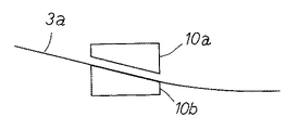
また、図4に示されるように、クランプ装置10は前方側へ突出した鋼板3aの先端部が斜め上を向くようにクランプするよう構成されている。このように、鋼板3aの先端部を斜め上に向けた状態で搬送することにより、鋼板3aの先端部が垂れ下がるのを確実に防止している。
As shown in FIG. 4, the
なお、図5に示されるように、ペイオフリール1の出側には、クランプ装置10で鋼板3aの先端部をクランプする際に、鋼板3aの先端部を斜め上に持ち上げるリフトテーブル20が設置されている。このリフトテーブル20は、テーブル部材21の上下動によって鋼板3aの先端部を斜め上に持ち上げるよう構成されており、前記のクランプ装置10で鋼板3aをクランプする前に鋼板が垂れ下がるのを防止するよう構成されている。
As shown in FIG. 5, a lift table 20 that lifts the tip of the steel plate 3 a obliquely upward when the
このようにして、鋼板3aの先端部は移送機構11に案内されて溶接機2の入側にあるピンチロール4まで引き出されるが、クランプ装置10により鋼板3aの先端部をクランプした状態で引き出されるため、鋼板3aの先端部の垂れ下がりが防止されることは前述のとおりである。
一方、ピンチロール4は、図6に示されるように、固定ロール4aと上下に動く移動ロール4bを有しており、待機時は移動ロール4bが上昇していて鋼板3aの先端部の受け入れ態勢が準備されている。そして、鋼板3aの先端部が挿入されると移動ロール4bが下降して固定ロール4aとの間でしっかりとクランプするよう構成されている。この結果、鋼板3aの先端部は溶接機2に対して常に正確に位置合わせが行われるため、溶接機2にセットされた先行する鋼板3bと位置ズレを生じることなく高精度に溶接が行われることとなる。
In this way, the leading end of the steel plate 3a is guided to the
On the other hand, as shown in FIG. 6, the
以上の説明からも明らかなように、本発明はペイオフリール1と溶接機2の間に、ペイオフリール1から巻き戻した鋼板3aの先端部をクランプするクランプ装置10が搭載され、該クランプ装置10により鋼板3aの先端部をクランプした状態のままペイオフリール1側から溶接機2に向けて走行する移送機構11を設けたので、搬送中に鋼板3aの先端部が蛇行または垂れ下がることがなくなり、このため鋼板先端部を溶接機入側にあるピンチロール4に正確、確実かつ効率よく搬入することができることとなる。この結果、先行する鋼板3bの後端との間でしっかりと溶接がなされることとなる。
As is apparent from the above description, the present invention includes a
1 ペイオフリール
2 溶接機
3a ペイオフリールから巻き戻した鋼板
3b 溶接機にセットされた先行する鋼板
4 ピンチロール
5 搬送路
6 レール
10 クランプ装置
10a クランパー
10b クランパー
11 移送機構
12 車輪
13 モータ
20 リフトテーブル
DESCRIPTION OF SYMBOLS 1 Pay-off reel 2 Welding machine
Claims (3)
Priority Applications (1)
| Application Number | Priority Date | Filing Date | Title |
|---|---|---|---|
| JP2003424334A JP4262079B2 (en) | 2003-12-22 | 2003-12-22 | Steel plate tip conveyor |
Applications Claiming Priority (1)
| Application Number | Priority Date | Filing Date | Title |
|---|---|---|---|
| JP2003424334A JP4262079B2 (en) | 2003-12-22 | 2003-12-22 | Steel plate tip conveyor |
Publications (2)
| Publication Number | Publication Date |
|---|---|
| JP2005177832A JP2005177832A (en) | 2005-07-07 |
| JP4262079B2 true JP4262079B2 (en) | 2009-05-13 |
Family
ID=34784561
Family Applications (1)
| Application Number | Title | Priority Date | Filing Date |
|---|---|---|---|
| JP2003424334A Expired - Fee Related JP4262079B2 (en) | 2003-12-22 | 2003-12-22 | Steel plate tip conveyor |
Country Status (1)
| Country | Link |
|---|---|
| JP (1) | JP4262079B2 (en) |
-
2003
- 2003-12-22 JP JP2003424334A patent/JP4262079B2/en not_active Expired - Fee Related
Also Published As
| Publication number | Publication date |
|---|---|
| JP2005177832A (en) | 2005-07-07 |
Similar Documents
| Publication | Publication Date | Title |
|---|---|---|
| JP4262079B2 (en) | Steel plate tip conveyor | |
| JP2000024794A (en) | Method and equipment for continuous welding of strip steel plate in longitudinal direction | |
| JPH11285874A (en) | Method and equipment for continuously welding strip steel by laser | |
| JPH11319911A (en) | Continuous welding method of band steel plate welded in longitudinal direction and welding equipment | |
| JP3629161B2 (en) | Continuous welding method in the longitudinal direction of strip steel plate and its welding equipment | |
| JP3999349B2 (en) | Spiral steel pipe forming equipment | |
| US20220297242A1 (en) | Method for producing a welded t-beam or i-beam profile | |
| JPH0747407A (en) | Welding section of continuous processing line | |
| JP5116136B2 (en) | Welding apparatus installed on the entrance side of steel strip continuous treatment equipment and welding method thereof | |
| JP6076234B2 (en) | Cold rolling method and cold rolling equipment for steel sheet coil | |
| JP3201743B2 (en) | Strip metal joining equipment | |
| JPH05139B2 (en) | ||
| JPH11290912A (en) | Device for joining sheet bar of continuous rolling equipment | |
| JP3256136B2 (en) | Roll return method and apparatus for steel material transfer table with inter-working bogie | |
| JPH06142923A (en) | Method and device for joining end faces of metallic band sheet material | |
| JP2548138Y2 (en) | Strip tip threading device | |
| JPS6393533A (en) | Continuous bending work line device for tube | |
| JPH11285875A (en) | Method and equipment for continuously welding in longitudinal direction of strip steel by laser | |
| JP3517357B2 (en) | Metal plate connection device | |
| KR20040056327A (en) | Device of cold rolling for stainless steel | |
| JPH06238306A (en) | Method for transporting leader strip | |
| JPH1080791A (en) | Clamping equipment of flying joining equipment | |
| JPH04253596A (en) | Coil tail end holder | |
| JPH0810803A (en) | Method for joining sheet bar by insert sliding in fully continuous hot rolling | |
| JPH09151004A (en) | Carrying device for beltlike material |
Legal Events
| Date | Code | Title | Description |
|---|---|---|---|
| A621 | Written request for application examination |
Free format text: JAPANESE INTERMEDIATE CODE: A621 Effective date: 20050913 |
|
| A977 | Report on retrieval |
Free format text: JAPANESE INTERMEDIATE CODE: A971007 Effective date: 20080512 |
|
| A131 | Notification of reasons for refusal |
Free format text: JAPANESE INTERMEDIATE CODE: A131 Effective date: 20080516 |
|
| A521 | Request for written amendment filed |
Free format text: JAPANESE INTERMEDIATE CODE: A523 Effective date: 20080710 |
|
| TRDD | Decision of grant or rejection written | ||
| A01 | Written decision to grant a patent or to grant a registration (utility model) |
Free format text: JAPANESE INTERMEDIATE CODE: A01 Effective date: 20090116 |
|
| A01 | Written decision to grant a patent or to grant a registration (utility model) |
Free format text: JAPANESE INTERMEDIATE CODE: A01 |
|
| A61 | First payment of annual fees (during grant procedure) |
Free format text: JAPANESE INTERMEDIATE CODE: A61 Effective date: 20090206 |
|
| FPAY | Renewal fee payment (event date is renewal date of database) |
Free format text: PAYMENT UNTIL: 20120220 Year of fee payment: 3 |
|
| R151 | Written notification of patent or utility model registration |
Ref document number: 4262079 Country of ref document: JP Free format text: JAPANESE INTERMEDIATE CODE: R151 |
|
| FPAY | Renewal fee payment (event date is renewal date of database) |
Free format text: PAYMENT UNTIL: 20120220 Year of fee payment: 3 |
|
| FPAY | Renewal fee payment (event date is renewal date of database) |
Free format text: PAYMENT UNTIL: 20120220 Year of fee payment: 3 |
|
| FPAY | Renewal fee payment (event date is renewal date of database) |
Free format text: PAYMENT UNTIL: 20130220 Year of fee payment: 4 |
|
| FPAY | Renewal fee payment (event date is renewal date of database) |
Free format text: PAYMENT UNTIL: 20130220 Year of fee payment: 4 |
|
| S531 | Written request for registration of change of domicile |
Free format text: JAPANESE INTERMEDIATE CODE: R313531 |
|
| FPAY | Renewal fee payment (event date is renewal date of database) |
Free format text: PAYMENT UNTIL: 20130220 Year of fee payment: 4 |
|
| R350 | Written notification of registration of transfer |
Free format text: JAPANESE INTERMEDIATE CODE: R350 |
|
| FPAY | Renewal fee payment (event date is renewal date of database) |
Free format text: PAYMENT UNTIL: 20130220 Year of fee payment: 4 |
|
| S533 | Written request for registration of change of name |
Free format text: JAPANESE INTERMEDIATE CODE: R313533 |
|
| FPAY | Renewal fee payment (event date is renewal date of database) |
Free format text: PAYMENT UNTIL: 20130220 Year of fee payment: 4 |
|
| R350 | Written notification of registration of transfer |
Free format text: JAPANESE INTERMEDIATE CODE: R350 |
|
| FPAY | Renewal fee payment (event date is renewal date of database) |
Free format text: PAYMENT UNTIL: 20140220 Year of fee payment: 5 |
|
| S533 | Written request for registration of change of name |
Free format text: JAPANESE INTERMEDIATE CODE: R313533 |
|
| R350 | Written notification of registration of transfer |
Free format text: JAPANESE INTERMEDIATE CODE: R350 |
|
| LAPS | Cancellation because of no payment of annual fees |