JP4262013B2 - Image processing method and image generation apparatus - Google Patents
Image processing method and image generation apparatus Download PDFInfo
- Publication number
- JP4262013B2 JP4262013B2 JP2003204669A JP2003204669A JP4262013B2 JP 4262013 B2 JP4262013 B2 JP 4262013B2 JP 2003204669 A JP2003204669 A JP 2003204669A JP 2003204669 A JP2003204669 A JP 2003204669A JP 4262013 B2 JP4262013 B2 JP 4262013B2
- Authority
- JP
- Japan
- Prior art keywords
- image
- camera
- setting
- reconstructed
- viewpoint position
- Prior art date
- Legal status (The legal status is an assumption and is not a legal conclusion. Google has not performed a legal analysis and makes no representation as to the accuracy of the status listed.)
- Expired - Fee Related
Links
Images


Classifications
-
- H—ELECTRICITY
- H04—ELECTRIC COMMUNICATION TECHNIQUE
- H04N—PICTORIAL COMMUNICATION, e.g. TELEVISION
- H04N5/00—Details of television systems
- H04N5/76—Television signal recording
- H04N5/765—Interface circuits between an apparatus for recording and another apparatus
- H04N5/77—Interface circuits between an apparatus for recording and another apparatus between a recording apparatus and a television camera
- H04N5/772—Interface circuits between an apparatus for recording and another apparatus between a recording apparatus and a television camera the recording apparatus and the television camera being placed in the same enclosure
-
- H—ELECTRICITY
- H04—ELECTRIC COMMUNICATION TECHNIQUE
- H04N—PICTORIAL COMMUNICATION, e.g. TELEVISION
- H04N5/00—Details of television systems
- H04N5/222—Studio circuitry; Studio devices; Studio equipment
- H04N5/262—Studio circuits, e.g. for mixing, switching-over, change of character of image, other special effects ; Cameras specially adapted for the electronic generation of special effects
-
- H—ELECTRICITY
- H04—ELECTRIC COMMUNICATION TECHNIQUE
- H04N—PICTORIAL COMMUNICATION, e.g. TELEVISION
- H04N5/00—Details of television systems
- H04N5/76—Television signal recording
- H04N5/78—Television signal recording using magnetic recording
- H04N5/781—Television signal recording using magnetic recording on disks or drums
-
- H—ELECTRICITY
- H04—ELECTRIC COMMUNICATION TECHNIQUE
- H04N—PICTORIAL COMMUNICATION, e.g. TELEVISION
- H04N5/00—Details of television systems
- H04N5/76—Television signal recording
- H04N5/84—Television signal recording using optical recording
- H04N5/85—Television signal recording using optical recording on discs or drums
-
- H—ELECTRICITY
- H04—ELECTRIC COMMUNICATION TECHNIQUE
- H04N—PICTORIAL COMMUNICATION, e.g. TELEVISION
- H04N5/00—Details of television systems
- H04N5/76—Television signal recording
- H04N5/907—Television signal recording using static stores, e.g. storage tubes or semiconductor memories
-
- H—ELECTRICITY
- H04—ELECTRIC COMMUNICATION TECHNIQUE
- H04N—PICTORIAL COMMUNICATION, e.g. TELEVISION
- H04N9/00—Details of colour television systems
- H04N9/79—Processing of colour television signals in connection with recording
- H04N9/80—Transformation of the television signal for recording, e.g. modulation, frequency changing; Inverse transformation for playback
- H04N9/82—Transformation of the television signal for recording, e.g. modulation, frequency changing; Inverse transformation for playback the individual colour picture signal components being recorded simultaneously only
- H04N9/8205—Transformation of the television signal for recording, e.g. modulation, frequency changing; Inverse transformation for playback the individual colour picture signal components being recorded simultaneously only involving the multiplexing of an additional signal and the colour video signal
Description
【0001】
【発明の属する技術分野】
複数の撮影画像から任意の視点からの画像を再構成するものに関する。
【0002】
【従来の技術】
従来より、撮影した画像から任意視点の画像を生成する試みが行われてきた。例えば、ステレオ計測の技術を用いて2枚以上の画像から対象物の形状を求め、コンピュータグラフィックス(以下、CG)の技術を用いて任意視点位置の画像を生成するという手法である。しかし、この方法は、2枚以上の画像において対応する点を同定する必要があり、条件によってはその作業が非常に困難なため、生成画像の画質が低いという問題があった。これに対して、イメージベースト・レンダリング(IBR)と呼ばれる技術、特に空間中を飛来する光線を獲得し、それを用いて任意視点の画像を生成する手法は、画像(画像はカメラのレンズを通過する光線を記録したものである)を撮影する際のカメラの位置、姿勢を計測しておけば、原理的に正しい任意視点画像を生成できるという利点がある。この基本原理は以下のとおりである。
【0003】
図31(a)はCCDカメラで物体を撮影しているところを模式的に表したものである。通常の撮像面はCCDであるが、説明の都合上、レンズ中心に対して対称に折り返した仮想面を撮像面と仮定し、さらに説明を単純化するために、撮像面は1次元ラインセンサで構成されていると考える。図31(b)に示すように、直線L上の任意の視点での多視点画像を得ることができる場合、視点位置Qで観察できる画像の画素iの色は画素iと視点位置Qを結ぶ直線が直線Lと交差する点Rを視点位置とする画像の画素i’の色と同じである。従って、再構成したい画像の全ての画素に対して、この対応関係を求めることにより、撮影していない全く新規な視点位置での画像を再構成できる。このような手法の代表例である“Light Field Rendering”(M.Levoy andP.Hanrahan著,Proc.SIGGRAPH96,31−42頁 1996年発行)では、図32に示すように格子上の各位置にカメラを配置して画像を撮影し、光線を獲得している。
【0004】
【特許文献1】
特開平10−097642
【非特許文献1】
“Light Field Rendering”(M.Levoy andP.Hanrahan著,Proc.SIGGRAPH96,31−42頁 1996年発行)
【0005】
【発明が解決しようとする課題】
しかしながら、上記の例では、光線を獲得するためにあらかじめ複数の視点位置で画像を撮影し、それらの画像を一旦記憶装置に格納し、それを用いて任意視点の画像を生成しているため、複数の画像を格納するための記憶エリアを確保しておく必要があった。特に、撮影画像の枚数が、生成する任意視点画像の画質に影響するため,高画質に再現しようとすれば、多数の画像を撮影する必要があり、その結果,撮影画像を記憶しておく記録装置の容量も膨大なものとなっていた。このことはパソコンのような大容量の記録装置を接続可能な機器においては何とか対応可能であるが、例えば、小型のデジタルカメラのような機器においてはメモリ容量に制限があるため、非常に大きな問題となる。
【0006】
また、イメージベースト・レンダリング技術を用いてデジタルカメラのような撮影装置を構成する場合、例えば、ユーザがスタートボタンを押して画像再構成が開始されると、現在どのような状況にあるのか、また、いつになったら処理が終了するかなどが把握できず、これを使用するユーザにストレスを与えるという問題が生じる。
【0007】
本発明は上記点に鑑みてなされたものであり、撮影に使用するメモリ容量の低減を図ることを目的とする。
【0008】
また、本発明は、ユーザのストレスを軽減することを目的とする。
【0009】
【課題を解決するための手段】
上記目的を達成するために、本発明は以下の構成を有することを特徴とする。
【0010】
本願請求項1記載の発明は、複数の撮影画像から任意の視点からの画像を再構成する画像処理方法であって、視点位置を設定する設定工程と、撮影画像を入力する入力工程と、前記撮影画像から、前記設定された視点位置からの画像を再構成するために必要な光線データを抽出する抽出工程とを備え、前記再構成画像が生成できるまで、前記入力工程と前記抽出工程を繰り返すようにし、さらに前記再構成画像の生成状況を報知する工程を有することを特徴とする。
【0011】
本願請求項9記載の発明は、複数の撮影画像から任意の視点からの画像を再構成する画像処理方法であって、視点位置を設定する設定工程と、撮影画像を入力する入力工程と、前記撮影画像から、前記設定された視点位置からの画像を再構成するために必要な光線データを抽出する抽出工程と、再構成途中と前記撮影画像とを表示部に切り替え表示する表示工程とを備えることを特徴とする。
【0012】
【発明の実施の形態】
(第1の実施形態)
以下、本願発明の第1の実施形態に係る撮影装置の図を参照しながら詳細に説明する。
【0013】
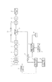
図1は第1の実施形態に係る撮影装置のブロック図である。
【0014】
図1において、1は撮影レンズ、2は絞り機能を具備するシャッタ、3はCCD等により光学像を電気信号に変換する撮像素子、4はレンズや絞りや撮像素子を含む撮像部の一部、5はガンマ補正等の公知のカメラ信号処理を行うプロセス回路、6はプロセス回路5のアナログ出力をデジタル信号化するA/D変換器、7はA/D変換器6より出力された画像データを記憶するメモリ、8は再構成画像の情報を設定する再構成画像情報設定手段、9は再構成画像情報設定手段8の情報から再構成に必要となる光線情報を算出して保持し、判定手段13から通知された光線情報を保持している光線情報から削除し、さらに保持している光線情報をメモリ14に出力する再構成用光線情報算出手段、10はカメラの位置・姿勢を計測するためのカメラ位置・姿勢計測手段、11は撮影にしているカメラの情報(撮影エリアの画角、撮像素子の画素数など)を獲得するカメラ情報取得手段、12はカメラ情報取得手段11の情報とカメラ位置・姿勢計測手段からの情報をもとにカメラが獲得している光線情報を算出する実カメラ光線情報算出手段、13は再構成用光線情報算出手段9の出力する光線情報が実カメラ光線情報算出手段12の出力する光線情報に含まれているか否かを判定し、一部でも含まれている場合は含まれている光線の情報を画素抽出手段19および再構成用光線情報算出手段9に通知する判定手段、14は再構成用光線情報算出手段9の情報を記憶するメモリ、22は画素抽出手段19の情報を記録するメモリ、21はメモリ22の情報を表示する表示手段、23はメモリ22に記録された情報を外部の記憶装置(ハードディスクやコンパクトフラッシュ(R)、その他の外部メモリ、CD−RやDVD−Rなどの記録メディア)とやりとりするためのインターフェース、24はハードディスクやメモリカード、CDやDVDなどの外部記録装置である。これらの各手段は不図示のコントローラにより制御されている。
【0015】
図2は、本実施形態の処理の流れを示すフローチャートである。ステップS1にて撮影にかかわる各種初期設定が行われ、ステップS2にて再構成したい位置Gp・姿勢Gdにおける光線情報Grの算出が行われる。ここで光線情報Grは、位置Gpを通過する光線のうち、設定された再構成画像の画角と画素数によって決まる直線の集合として表現される。3次元空間中の直線(光線)Lijの式は、視点位置GP=(xP,yP,zP)、撮像面上の各画素の位置Eij=(xij,yij,zij)とすると、
【外1】

で与えられる。ただし、
【外2】
![]()
(式1)中の分母のうち、1つが0ならば、その項に関係する軸を除いた2軸で規定される平面上の直線となり、2つが0ならばそれらに関係する軸を除いた軸に直交する直線となる。例えば、xij−xP=0ならばYZ平面に平行な直線となり、xij−xP=yij−yP=0ならばZ軸に平行な直線となる。仮想カメラの撮像面の総画素数がN個であれば、直線もN本存在する。仮想カメラの撮像面の各画素の位置は、仮想カメラの姿勢、仮想カメラの画角と撮像面の画素数、1画素のサイズが分かれば、仮想カメラの光学中心(再構成画像の視点位置)に対する相対的な位置として計算できる。これら視点及び画素位置の具体的な求め方は後に詳述する。次にステップS4にて画像を実際に撮影する。ステップS5ではステップS4で撮影した際のカメラの画角、画素数やカメラの位置Cq・姿勢Cdを取得し、ステップS6にてCqの位置及び撮像面の各画素の位置を算出する。ステップS7ではカメラで獲得された光線情報Cr(視点位置と撮像面の各画素の位置とで表現される直線)とGrを比較し、Crの一部でもGrに含まれていたならばステップS8に進み、まったく含まれていなければステップS3に戻る。光線群Crの一部がGrに含まれているかどうかの判定は、(式1)で与えられるGrの各直線の式に、S6で求めた視点位置と撮像面の各画素位置を代入し、その式を満足するかどうかを見ればよい。そして、式を満足するならば含まれる(光線が一致する)、満足しなければ含まれないと判定する。ステップS8ではGrに含まれているCrの光線の色(画素値)を獲得し、撮影済みの光線情報の処理を行う。ステップS9では、再構成したい画像を構成するすべての画素について画素値を特定したならば処理を終了し、そうでなければステップS4に戻って、前述の処理を繰り返す。この一連の処理により、再構成画像を獲得することが可能となる。特に、再構成画像を得るために大容量の記憶手段を必要としていた従来手法に比べて、画像を撮影して必要な画素値のみを抽出し別のメモリに記録することにより、撮影用のメモリ7の容量が画像1枚分ですむというメリットが生まれる。
【0018】
図3は各種設定処理を説明するためのフローチャートである。ステップS31では、撮影に関するさまざまな情報を初期設定値として与える。たとえば、画素値の出力ビット数、アイリス、シャッタースピードなど、通常のデジタルカメラで行われている初期化処理と同様のことを行う。本実施形態では、画像獲得の際に画角や画素数などのカメラ情報を毎回取得するようにしているので必要ないが、画角や画素数が固定のカメラの場合は、この時点で画角や画素数を設定することも可能である。
【0019】
図4は画像獲得処理S4の処理の流れを示すフローチャートである。ステップS40にて、撮影に使用しているカメラの画角や撮像部の画素数などの情報が取得される。もし、画角や画素数が撮影中に変化しないということであれば、初期設定で与えられた画角と画素数をそのまま使用すればよい。その場合はこのステップを削除することが可能である。次に、ステップS41にて1枚分の画像が撮影され、ステップS42にてγ補正処理、ステップS43にてA/D変換、ステップS44にて色補正、歪補正などが行われ、ステップS45にて補正処理されたディジタルデータをカメラ内部のバッファメモリに格納する。
【0020】
図5は画素値獲得処理S8の流れを示すフローチャートである。まず、ステップS51にて光線情報Crのうち、Grに含まれている光線(Gr中の光線と一致する光線)情報をリスト化する。次にステップS52においてリストの先頭の光線情報に対応する撮影画像中の画素を特定し、ステップS53にてその画素値を抽出する。ステップS54にてメモリ22中の対応する位置に(たとえば、注目した光線が再構成画像中の(i、j)画素に相当する場合は、メモリ22中の再構成画像の(i、j)画素に対応する部分に)その画素値を記録する。ステップS55では、後に、再構成に必要な光線群のうち、獲得済みの光線情報が識別できるように今獲得した画素にマークをつける。これは1画素を例えば4バイトで記録することにしておき、画素値(RGB)に3バイト、識別情報に残り1バイト中の1ビットを割り当て、そこにマークすることで実現できる。この処理を終えると、リストの先頭の光線情報を削除し、次の光線情報に着目する。もし、次に光線情報が存在しなければ(ステップS57)、画素値獲得処理を終了し、メインルーチンのステップS9に戻る。そうでない場合は、ステップS52に戻る。
【0021】
S51においてGrに含まれる光線情報をリスト化する際は、メモリ22を参照しながら、既に獲得済みの光線(メモリ中の対応する位置にマークがついたもの)に関しては除外する。または、再構成に必要な光線情報Grのうち、既に獲得済みのものを除外した光線情報Hrを生成しておき、Crとの比較にはHrを用いることで、光線を重複して求めることがなくなり、効率化が図れる。
【0022】
これらの一連処理により、ある時点で撮影された画像に含まれる、再構成に必要な光線(画素)情報を抽出することができる。
【0023】
図6は、ステップS33で設定される情報を説明するための図である。ステップS33で設定される情報としては、基準座標系、再構成画像の姿勢、視点位置、画素数、画角の5つである。これらの情報の設定に関して図7を用いて説明する。カメラには位置・姿勢センサが内蔵あるいは外付けにされており、時々刻々とその時点での位置・姿勢に対する相対的な位置姿勢を出力する。まず、ステップS71にて基準座標系の設定を行う。これは基準座標系設定ボタンを用意しておき、設定ボタンが押されると、その時点でのカメラの光学中心の位置を原点とした、カメラの光軸をZ軸、カメラの撮像面(CCD)の横方向をX軸、縦方向をY軸とする基準座標系が設定される。この様子を図8に示す。実際のカメラでは光学中心(原点)Oの後方に撮像面が存在するが、ここでは原点Oに対して折り返した位置に仮想撮像面100を考える。これはコンピュータ・グラフィックスやコンピュータ・ビジョンの分野でよく用いられる表現方法であり、このように考えても、一般性は保たれる。基準座標系の設定が終わると、図6のように基準座標系の欄に、設定が終わったことが分かるように「設定済」という文字あるいはマークなどが表示される。基準座標系が設定されると、カメラに内蔵されたセンサからは、基準座標系に対する相対的な位置・姿勢が出力される。次にステップS72において、再構成画像の姿勢を設定する。カメラに内蔵されたセンサからは、基準座標系に対する位置・姿勢情報が出力されているので、再構成画像の姿勢決定モードにおいて、カメラの姿勢を所望の姿勢に変更して設定ボタンを押すことにより、基準座標系上での姿勢が決定され、その値が、「姿勢」の欄に表示される。再構成画像の姿勢は、z=−fに基準の撮像面があると考え、基準座標系の各軸(X、Y、Z)に対する回転量で表記する。例えば、図8では基準座標系の各軸をそれぞれ(θ,φ,ρ)回転させると再構成画像の姿勢になることを示している。次に、ステップS73において再構成画像の視点位置を設定する。これは、基準座標系の原点からの距離を直接入力することにより行う。ここでは、基準座標系でのX、Y、Zの値がそれぞれ(u,v,w)と入力されたものとする。このように与えた位置と姿勢は、再構成画像座標系(再構成画像の視点位置、すなわち仮想カメラの光学中心を原点とする基準座標系と同様な座標系)を考え、基準座標系を再構成画像座標系に一致させる時の平行移動量と回転量に相当する。ステップS74にて画素数(解像度)の設定を行う。画素数は、例えば、「VGA」「XGA」「SXGA」・・・「その他」の中から選択する。「その他」が選ばれた場合は、任意の画素数を直接入力する。その後、ステップS85において画角の設定を行う。画角に関しても、画素数の時と同様にあらかじめ代表的な値を選択できるようにし、その他を選んだときのみ任意の値を入力できるようにする。画角には水平、垂直の2種類の画角が設定可能であるが、CCDの1画素のアスペクト比および縦横の画素数が既知であれば、水平または垂直方向の画角のどちらか一方を決めれば、自ずから他の画角も決定される。それ故、ここでは、水平画角のみを設定する。
【0024】
図8は、カメラが基準座標系に対して、X、Y、Z軸の周りに(θ,φ,ρ)だけ回転し、(u,v,w)だけ平行移動したときのカメラの各画素位置の求め方を説明するための図である。基準座標系を設定したときのカメラの撮像面100はZ=‐f(fは焦点距離)の位置に存在する。また、一画素の縦横の大きさをそれぞれp、q、縦画角、横画角をそれぞれωx,ωy、縦横の画素数をそれぞれm、nとすると、基準座標系における撮像面の(i、j)画素110の位置(ただし、(0、0)は左上隅とする)は、
【外3】
となる。また、以下の関係が成り立つ。
【外4】
従って、(式2)は(式4)のように書くことができる。
【外5】
任意の位置・姿勢にあるカメラの各画素の位置(x’,y’,z’)は、(式4)で与えられる各画素の位置に回転と平行移動を施すことにより求めることができる。
図9に示すように座標系を仮定すると、Z軸中心の回転Rz、X軸中心の回転Rx、Y軸中心の回転Ryはそれぞれ次式のように表せる。
【外6】
Z軸回転→X軸回転→Y軸回転という3つの回転変換を掛け合わせると最終的な回転変換Rが次式のように表現できる。
【外7】
従って、任意の位置・姿勢にあるカメラの各画素の位置(x’,y’,z’)は、基準座標系上では、
【外8】
となる。また、そのときのカメラの視点位置は(u,v,w)となる。
【0031】
以上述べたように、最初に所望の視点位置を入力し、その視点位置で画像を再構成するために必要な光線情報を計算し、その光線を収集していくというプロセスを経ることにより、従来よりも少ないメモリ量で画像の再構成が行えるという効果が生じる。
【0032】
また、基準座標系に対する回転と平行移動により移動後の画素位置を演算することにより、単純な演算で求めることができ、演算の高速化が図れる。
【0033】
(第2の実施形態)
図10は撮像部3をCCDタイプからCMOSセンサ27に変更した場合のブロック構成図である。これ以降のその他の実施形態を含め、図中の同じ番号を有するブロックは特に断らない限り同一の機能を有するものとし、説明を省略する。
【0034】
CMOSセンサは画素単位に値を出力することができるため、画素抽出手段19よりCMOSセンサに直接画素を特定するアドレスを出力して対応する画素値を受け取り、プロセス5、A/D変換6を経てメモリ22に格納することが可能である。
【0035】
このように撮像部にCMOSセンサを利用することにより、撮影画像を一時記憶しておくメモリが不要となるためハードウェアを小型化、低コスト化できるというメリットがある。ただし、CMOSセンサはあくまでも一例であり、画素単位でデータを出力できる他のセンサを用いることが可能であることは言うまでもない。
【0036】
また、撮像素子として画素数が1画素のみのCCDを利用するの場合も、CMOSセンサの場合と同じように撮影画像を一時記憶しておくメモリが不要になるため、この方法によってもハードウェアを小型化、低コスト化できる。
【0037】
(第3の実施形態)
第1の実施形態、第2の実施形態では、再構成画像を表示するための表示手段を設けていないため、再構成をスタートすると現在どのような状況にあるか、どこまで再構成が済んでいるかといったことが把握できない。そこで、この実施形態では、図11に示すように、モニタ手段28を設け、撮影中の画像と再構成されている画像とをユーザが切り替えて表示することができるようにしたものである。もちろん、第2の実施形態に対して同様のモニタ手段を設けることが可能であることは言うまでもない。
【0038】
図12はモニタ手段28のブロック構成図である。図中、20はメモリ7とメモリ22とに格納されている情報を切り替える切替表示手段、21は切替表示手段20からの情報を可視化する表示手段である。
【0039】
ここでは、撮影中の生の画像と再構成途中の画像とを切り替えるようにしているが、再構成画像のみを表示するようにしてもよい。また、撮影中もユーザの指示により、あるいはタイマーを設けて一定時間毎に再構成途中の画像と撮影画像とを切り替えて表示することも可能である。画像再構成中は、頻繁に再構成途中の画像を確認することが多いと思われるので、切り替え用のスイッチを撮影装置につけておくと便利である。特に、1回の操作により切替のできる押しボタン、スライダー、ダイヤル式のスイッチが望ましい。
【0040】
また、再構成画像を直接観察できなくても、生成状況を示すインジケータを付加しておけば、どの程度再構成されたかが分かるので、ユーザのストレスを軽減できる。インジケータは、全体の何パーセントが再構成されたかを数値(テキスト)で示してもよいし、棒グラフのようなもので視覚的に示してもよい。
【0041】
また、再構成が終了した時にブザーなどでユーザに通知するとユーザは出来上がりのタイミングを気にせずに撮影に専念できるというメリットが生じる。
【0042】
(第4の実施形態)
第3の実施形態では再構成途中の画像を表示できるようにしたが、光線が獲得できていない画素は値が未定となり、表示できないので、例えば、図13(a)のように表示される。ただし、ここではタイル状のブロックを1画素(1本の光線)と見なして便宜的に表している。光線の取得が進むと最終的には図13(b)のように表示されるが、途中の段階では、(a)のように部分的に再構成された画像となる。そこで、図13(a)の画像を補間して表示することにより、途中結果の画像をより高画質に表現する。通常は、再構成に必要な光線を全て取得するまで処理が続けられるが、この補間処理によって十分に高画質な再構成画像が得られれば、それ以上処理を続ける必要は無い。この場合、光線を取得する時間が短縮されるため、より高速な画像再構成が可能となる。
【0043】
図14は、第3の実施形態のモニタ手段28を一部変更したときのブロック構成図である。1011はメモリ22の情報を使って未定画素値を推定する補間手段であり、補間結果の画像を切替制御手段20に出力する。切替制御手段20では、ユーザの指示、あるいはタイマーなどにより一定時間毎に撮影画像情報(メモリ7)と再構成画像情報(メモリ22)と補間画像情報とを切り替えて表示手段21に出力し、表示手段21では切替制御手段20からの情報を可視化する。もし、補間画像の品質が十分であると判断できれば、この時点で再構成処理を終了する。この判断はユーザ自身が補間画像を見ながら行ってもよいし、取得できた光線の数を基準にしてもよい。光線の数を基準にする場合は、例えば再構成に必要な光線全体の2/3の光線が獲得できれば、あとは補間処理で補うなどの方法が考えられる。
【0044】
補間処理に関しては、一般的なキュービック補間やバイリニア補間などを用いることができる。また、再構成に必要な光線とは若干異なるが、近接した位置で獲得される光線を近似値として利用してもよい。例えば、正確には、カメラを数cm移動させて撮影した時の光線が必要である場合、カメラを移動させずに、今撮影した画像の中からその光線に近いものを選んで代用する。
【0045】
また、補間処理などを使って再構成が終了したときにブザーなどで通知するとユーザは出来上がりのタイミングを気にせずに撮影に専念できる。
【0046】
このように補間処理を導入することで、画像再構成に要する時間を短縮でき、効率的な撮影が可能になるというメリットがある。
【0047】
(第5の第5の実施形態)
図13(a)のように再構成が進行している時、ユーザは再構成後の画像を予測することが可能である。通常、画像再構成は1画面分行われるが、被写体によっては1画面全てを再構成する必要は無いかもしれない。例えば、写っている「パソコン」の部分が十分に再構成できていれば、すなわち、ユーザの望む部分だけ高速に画像を再構成したほうがユーザのニーズに合致しているかもしれない。そこで、本実施形態では、ユーザに画面中の再構成して欲しい領域を指定することが可能な手段について述べる。
【0048】
図33は、第4の実施形態に対して領域設定手段3301と解像度指定手段3302を追加した場合のブロック構成図である。領域設定手段3301は再構成画像中の部分領域を設定し、解像度指定手段3302は必要に応じてそれぞれの部分領域に対して再構成する画像の解像度を指定する。再構成用光線情報算出手段3310は、再構成画像情報設定手段8、メモリ14、領域設定手段3301、解像度指定手段3302からの情報をもとに必要な光線情報を算出する。
【0049】
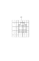
図15(a)は、領域設定手段3301と解像度指定手段3302を説明するために示したカメラの概観(背面部分の一例)である。1501はスタートボタン、1502は電源ボタン、1503はモードセレクトボタン、1504は選択されたモードにおいて次のデータに移るためのボタン、1505は選択されたモードにおいて前のデータに戻るボタン、1506は設定ボタンである。モードセレクトボタン1503に関しては実施形態6にて説明するため、ここでは割愛する。1507はファインダー、1508は撮影データあるいは再構成中の画像あるいは補間された画像などを表示するためのディスプレイ、1509は再構成領域を指定するための形状を指示するボタンで、例えば、モードが領域設定にセットされた状態で矢印を押すと順に「丸」⇒「四角」⇒多角形⇒・・・と変化し、その形状がディスプレイ1508に表示される。図15(b)にその様子を示す。ここでは、「円」が指定された状態である。1510と1511はそれぞれ表示された図形(ここでは円)を縮小または拡大するためのボタンであり、このボタンを操作することにより、領域の大きさを設定する。1512は表示された図形を上下左右に移動させるためのボタンである。このボタン1512を操作して希望する位置に図形(円)をあわせ、設定ボタン1506を押すと領域が確定される。こうして領域が指定されるとこれ以降は指定された領域内のみが再構成される。ここでは、指定可能な領域の形状として、円や多角形に関して述べたが、任意の形状を指定できるようにしてよい。任意形状を指定する場合は、画面中に「点」を配置し、それを直線あるいは曲線でつなぐというユーザインタフェースにすればよい。
【0050】
また、場合によっては、目的の被写体のみ高解像度であればその周囲の解像度はあまり高くなくてもよいが、無ければ困るといった状況も存在する。解像度指定手段3302は、このような状況に対処するための設定領域内の解像度を指定する手段である。解像度の設定に関しては、図16(a)に示すように、再構成している画像を、高解像度に再現したい部分のみ再帰的に分割して解像度を上げる。ここでは周囲に比べて指定された領域1601の方が縦横それぞれ2倍ずつ解像度が高くなっている。具体的な操作として、設定領域の解像度の指定は、モードセレクトボタン1503で解像度の設定を選び、ボタン1512を操作することでプリセットされていた解像度を呼び出してセットすることにより行う。この例では指定領域の解像度を周囲に比べて縦横2倍の解像度に設定したが、この例に限らず任意の倍率に設定してもよい。ただし、設定する際に解像度を2のべき乗倍(クワッド・ツリー構造)になるように選ぶと処理が簡単になる。
【0051】
本実施形態では、再構成画像中の指定できる領域は1箇所として説明したが、もちろんこれに限らず、複数箇所でもよい。その場合は、前記の指定処理を必要な領域の数だけ行えばよい。
【0052】
また、複数の領域を指定した場合の解像度の指定も、それぞれ異ならせて行っても、指定領域内すべてを同一の解像度にしてもよい。また、複数の領域を指定する際に、指定した領域Aの内部に新たに領域Bを指定することも可能である。この場合、領域Bの解像度を高く、領域Aの解像度は中程度に、その他の領域は低解像度に設定すれば、ユーザの注目している領域に近いほど高解像度に画像生成できる。
【0053】
以上述べたように、ユーザに再構成する領域を指定するためのユーザインタフェースを撮影装置に付加することにより、希望の領域のみを再構成することができ、全体の処理速度が向上させることができる。
【0054】
(第6の実施形態)
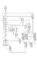
図17は、第3の実施形態にモード設定手段15と未撮影エリア情報算出手段16と表示手段17を追加した場合の実施形態を表している。
【0055】
モード設定手段15は、図19のモードセレクトボタン1503と連動する。例えば、モードセレクトボタン1503を押すと、ディスプレイ1508にモード情報が表示され、もう一度押すと消える。モードとしては、ディスプレイ1508に撮影中の画像を表示するか再構成中の画像を表示するかあるいは表示をオフにするかを示すモード、未撮影領域をディスプレイ1512に表示/非表示するモード、領域設定や解像度を指定するモードなどがある。各モードが表示されているときに、ボタン1504を押すと順にモードの種類が変更され、ボタン1506を押すと表示されたモードに固定され、この状態で1504、1505を操作するとそのモードの設定情報を変更できる。たとえば、数値入力の際にはあらかじめ決められたステップでそれぞれ値を加算、減算し、数値以外のデータの場合は、あらかじめ決められた順番のデータをそれぞれ順方向、逆方向に変更する。設定されたモードが撮影画像の表示であれば、ディスプレイ1508に撮影画像を表示し、再構成中の画像を表示する設定であれば再構成中の画像を表示し、そうでなければ、1508の表示はオフにする。また、未撮影エリア情報表示がエリア表示モードの場合は、ディスプレイ1512に未撮影エリアを表示し、表示モードが未取得光線情報の表示であれば未取得光線情報を表示し、そうでなければ表示をオフにする。ここではディスプレイ1508のほかに別途ディスプレイ1512を設けたが、ディスプレイ1508に両者の画像やモード情報を切り替えて表示することにより、ディスプレイ1512を削減することができる。
ここで図17の表示手段17とディスプレイ1512とは同じものである。
【0056】
次に未撮影エリア情報の表示方法について説明する。未撮影エリア情報の表示方法としては、
(a) 3次元空間(をレンダリングしたもの)の中に、撮影が必要な地点に色をつけて表示するとともにカメラの位置をその中で示す。
(b) 3次元空間(をレンダリングしたもの)の中に、未取得の光線を表示するとともに実際に撮影しているカメラの位置をその中で示す。
(c) 撮影しているカメラに対して相対的にどの方向にどの程度移動し、カメラの姿勢をどのように保ったらよいかというナビゲーション情報を表示する。
(d) (a)〜(c)に関して音声で情報を知らせる。
等がある。
【0057】
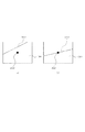
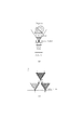
図18は上記(a)の場合を説明するための図である。1512は未撮影エリア情報を表示するためのディスプレイ、図中の142、144はそれぞれ3次元空間を平面図(Y=0)と立面図(Z=z1)で表したもの、141、145の★印は3次元空間におけるカメラの位置を平面図および立面図中に記したもの、142をはじめとする色のついた部分(網がかかった部分)は未撮影エリアを表している。ただし、カメラの3次元空間中の位置を(x1、y1、z1)とする。立面図はZ=z1の平面であるので、カメラの移動にともなって表示される未撮影エリア情報が変化する。撮影者はこれらの情報を参照しながら、カメラを未撮影エリアに移動させ、必要な光線を獲得する。図18では、カメラの姿勢情報は表現されていないため、光線の獲得は全ての方向にカメラを向けて撮影する必要がある。これを改善するために、別途、カメラの姿勢に関する表示を設けることも可能である。このときの表示方法としては、視点位置を先端とする角錐で、その地点で獲得が必要な光線を囲むように表示すれば、カメラをどの方向に向ければよいかが把握できるので、効率的な光線の獲得が可能となる。別の例を図20にしめす。図中の151は3次元シーンに未撮影エリアを重畳表示したもの、152は重畳された未撮影エリア、153は平面図(Y=0)上で示した未撮影エリア、154と156はカメラの位置、155は平面図(Y=0)、157は立面図(Z=z1)である。この例では、図18の平面図、立面図に加えて、3次元シーン中に未撮影エリアを重畳したものを表示する。この3次元シーンは現時点でのカメラの映像を利用し、これに未撮影エリアを重畳して生成する。このように表示することで、見ているシーンに対してどのようにカメラを移動させればよいかが直感的に分かるので、さらに効率的なカメラの移動が可能となり、光線の獲得が容易となる。
【0058】
図21は上記(b)の場合を説明するための図である。説明を簡単にするために、9本の光線を獲得すると画像再構成が終了すると仮定する。そして、ここでは1本のみ光線が獲得されている状況を示している。図中の211は未撮影光線情報、212はY=0平面に投影した未撮影光線情報、213(図中の8個の黒丸)はZ=z1で切った断面における未撮影光線情報を表している。このように表示することで、カメラをどの位置に持っていけば光線が取得できるかが一目でわかるため、効率的な光線情報の取得が可能となる。また、直接獲得すべき光線を示すことで、カメラをどの方向に向ければよいかも直感的に把握できる。
【0059】
図22は矢印によるナビゲーションの様子を示している。220はカメラを移動すべき方向を示す矢印、221はカメラの光軸を含む水平面において、カメラをどの方向に向ければよいかを示す水平角度メータ、222は光軸を含む垂直面においてカメラをどの方向に向ければよいかを示す垂直角度メータである。220の矢印に沿ってカメラを移動しながら、221中の矢印が光軸(円の中心を通る線分223)と一致するように、かつ、222中の矢印が光軸(線分224)と一致するようにカメラの方向を制御することにより、効率的に光線を獲得することができる。
【0060】
また、上記(d)の音声によるナビゲーションは、例えば、
・「前方3m直進」という音声に従って移動すると目的の地点で「止まれ」という合図
・「右に回転」という音声に従って回転すると目的の角度で「止まれ」という合図
・「上方向に回転」という音声に従って回転すると目的の角度で「止まれ」という合図
というように音声に従って移動・回転すると目的の光線が獲得できるというものである。この例はあくまでも一例であり、この他の指示を行ってもよい。
【0061】
以上述べたように、未撮影光線情報を提示する手段を設け、ユーザを誘導することにより、効率的にかつ短時間に目的の光線群を取得することが可能となる。
【0062】
(第7の実施形態)
実際に撮影を行っている場合に、不意の侵入物が撮影されることも考えられる。侵入物が存在すると本来の光線が獲得できていないということであるから、このような場合には撮影を無効にしてやり直すことが必要である。本実施形態では、侵入物に対する対処の方法について述べる。
【0063】
侵入物が存在する場合の対処法として、
1.ユーザが侵入物を認識して、一時的に撮影を無効にし、侵入物が写る前の状態までカメラを移動してやり直す。
2.侵入物の自動判定手段を設けて、フィードバック制御する。
が考えられる。ただし、侵入物が検知されても、獲得すべき光線に影響を与えなければ、獲得した光線や現在の撮影をキャンセルする必要はない。
【0064】
まず、1に関しては、ユーザが侵入物を発見した時点から、例えば数秒前の状態まで獲得した光線情報をキャンセルし、そこから撮影しなおすという方法である。獲得した光線情報と一緒にタイムコードなどを同時に記録しておけば、侵入物発見時のタイムコードと比較して、それよりもたとえば5秒前に戻すというように、以前の状態に復帰することができる。ただし、発見が遅れる場合もあり得るので、何秒前に戻すかは任意に設定できるようにするのが好ましい。
【0065】
図23は、第6の実施形態に侵入物警告手段231を設けた場合の例である。モード設定手段15により、ユーザが侵入物警告手段(ボタン)を押したときに何秒前に戻すかという情報が設定され、ボタンが押されると判定手段13を介してその秒数分だけ獲得した光線をキャンセルする。光線がキャンセルされるとキャンセルされた光線に対応する未撮影エリア表示に関わるデータもリセットされる。光線を獲得する処理の再開であるが、侵入物警告手段を再度押すと光線獲得が再開されるようにしてもよいし、ある秒数だけ経過した後に再開されるようにしてもよい。
【0066】
図24は、侵入物の検知をユーザが行うのではなく、自動処理にて行う場合の実施形態である。25は侵入物検知手段、26は切り替え制御手段、27は表示手段、28は音声再生手段である。侵入物検知手段25が侵入物を検知すると、判定手段13に対して獲得した光線をある時間分だけキャンセルするように指示を出す。この時間はモード設定手段によりあらかじめ設定された時間である。侵入物が検知されて処理が一時中断されるとその状況、例えば「侵入物あり」などというように表示手段27に視覚的に表示されるか、または音声再生手段28にて同様の警告がなされる。ここで切替制御手段26は、侵入物が存在する場合に、ディスプレイに表示するか、音声で警告するか、あるいは両者を同時に利用するかを制御する。
【0067】
侵入物検知手段25の動作について説明する。例えば、現在撮影している画像の1フレーム前の画像を保持しておき、現在の画像との間で動きベクトルを求める。対象物が静止している場合、カメラの移動による対象物の動きベクトルはおおよそ求めることができるので、その動きと明らかに異なる動きをしている物体が存在すれがそれが侵入物であると判定することができる。また、これ以外にも画面中の色(カラー)が大きく変化した場合も侵入物の存在を疑うことができる。
【0068】
以上述べたように、不意の侵入物を検知する手段を持つことにより、再構成したあとで邪魔なものが写りこんでいたというような不具合を解消でき、再構成に必要な光線を効率的に獲得することが可能となる。
【0069】
(第8の実施形態)
実際の撮影時には何らかの事情により、撮影(再構成)を一時中断しなければならない場合もある。そのような場合への対処法としてリジューム機能を付加した実施形態を図25に示す。
【0070】
18は撮影状態記憶手段であり、再構成途中の画像および獲得された光線情報、再構成に必要な各種パラメータを外部I/F23に出力し、外部記憶装置24に格納する。
【0071】
また、途中から処理を再開する場合には、外部I/F23を介して外部記憶装置24から再構成に必要な各種パラメータ、再構成画像、獲得済み光線情報などの情報を読み出し、メモリ14とメモリ22にセットする。
【0072】
このような構成にすることにより、不意の中断にも対処でき、目的の画像再構成を効率よく行うことができる。
【0073】
(第9の実施形態)
第1の実施形態では再構成画像の視点位置を3次元空間中の位置として直接入力する方法をとったが、本実施形態ではより簡便な視点位置設定方法を提供する。
【0074】
図26は、再構成画像用視点位置設定手段261を第8の実施形態に付加した場合の実施形態である。ここでは視点位置の設定方法として、
1.3次元位置を直接入力する
2.単眼カメラを2度利用してステレオ撮影し、位置・姿勢を求める
3.エビポーララインを利用して、位置・姿勢を指示する
4.ステレオカメラで計測し、位置・姿勢を支持する
などがある。1に関しては第1の実施形態にて述べたので、本実施形態では2〜4について説明する。
【0075】
図27は単眼カメラを利用して再構成画像の視点位置・姿勢を指示する処理のフローチャートである。まず、再構成画像の視点位置に何らかの目標物(目印)となるようなものが存在する場合は、ステップS271で目標物(目印)を特定する。次にステップS272にて光軸が目標物を貫通するように撮影する。このときのカメラの位置と姿勢を利用してローカル座標系を設定する。設定の方法は第1の実施形態で説明した方法と同様の方法を用いればよいため、ここでは省略する。次にステップS273にてカメラを移動させて撮影する。このときも同様に光軸が目標物を貫通するように撮影する。ここで、1回目に撮影した位置と2回目に撮影した位置との間の距離はステレオ計測を行う際のベースラインとなるため、ある程度大きくとるほうが位置精度が向上する。ステップS274において1回目と2回目の撮影の位置・姿勢からステレオ計測により、ローカル座標系での目標物の位置を算出する。そして算出された位置を再構成画像の視点位置にする。姿勢に関しては、第1の実施形態と同様の方法、すなわち、カメラを所望の姿勢に保ち、その時のカメラの姿勢センサが出力する姿勢を再構成画像の姿勢とすればよい。ステップS275にて決定された再構成画像の視点位置と姿勢を再構成画像視点位置・姿勢設定手段に出力する。
【0076】
次に、生成したい再構成画像の視点位置に目標物(特徴点、目印など)がない場合の方法について述べる。例えば、空中の一点を視点位置にしたい場合、第一の地点で空中の一点を決定すればその空中の一点をカメラの光軸が通過するように設定することは可能であるが、場所をかえると何も目印がないため第二の地点からその一点を特定することは難しい。従って、この「空中の一点」をターゲットにして、異なる2地点間でのステレオ計測により位置を求めることは難しい。そこで、第一の地点で「空中の一点」を決定し、その点を光軸が貫通するようにカメラをセットして、その時の位置と姿勢を記憶する。そして、第二の地点にカメラを移動させたときには、第一地点のカメラの光軸(直線)を第二の地点でのカメラ映像に重畳して表示する。この様子を図28を利用して説明する。図28(a)は第二地点でのカメラの映像に第一地点でのカメラの光軸を重畳した画像を表している。図中の2810は第一地点でのカメラの光軸、2820は現在のカメラの光軸(ここでは撮像面の中心を貫通する法線を仮定している)である。第一地点で決定された一点はこの直線2810上に存在する。図28(b)は図28(a)とは異なる地点でのカメラで撮影された画像であり、光軸2820が直線2810上に存在するようにカメラを移動させたものである。このように直線上の一点を光軸2820と一致させることにより「空中の一点」を特定することができ、その時のカメラの位置・姿勢と第一地点でのカメラの位置・姿勢とからステレオ計測により位置を算出することができる。姿勢は第1の実施形態と同様の方法で指定できる。
【0077】
以上述べたように、第二地点では、第一地点におけるカメラの光軸2810上の点を特定すればよいため、何も目印がないときに比べて「空中の一点」を特定しやすくなり、再構成画像の視点位置・姿勢を設定する作業が楽になる。
【0078】
また、3次元空間中の一点を指定する作業は、カメラをステレオカメラに変更すれば、よりダイレクトに行うことが可能となる。ステレオカメラの場合は、例えばファインダ内で立体視が可能な状態にしておき、空間中に何らかのマークやポインタなどを表示する。このマークやポインタを移動させて3次元空間中の一点を指定することにより、簡便に空間中の一点を指定することが可能となる。指定された一点の位置はステレオカメラを使っているので容易に算出することができる。姿勢の指定は、第1の実施形態と同様の方法により可能である。マークの移動に関しては、前後上下左右の6方向に移動させるボタンなどをカメラに備えてもよいし、カメラの光軸上の点を指定すると仮定すれば前後のみの2つのボタンを装備するだけでよい。ここでは、ファインダ内で立体視できるようにしたが、レンチキュラ・シートをディスプレイ1508あるいは1512に採用することにより立体視できるようにしてもよい。
【0079】
以上述べたように、カメラをステレオカメラに変更することにより、よりダイレクトに3次元空間中の一点を指定することが可能となり、作業効率が格段に向上する。また、2眼存在することにより、本来の目的である光線の獲得も1眼に比べてより効率的に短時間に行うことが可能となる。光線の獲得処理としては、一度に2地点分の光線が獲得できると考えれば、第1の実施形態で説明した処理を2回行うことにより対処できる。
【0080】
(第10の実施形態)
再構成画像の視点位置・姿勢と再構成画像の画角、画素数とを決定すると、必要な光線群が特定される。しかし、再構成画像の視点位置と実際にカメラで撮影可能な場所とが大きく離れていると、必要な光線を獲得するためには、広い範囲を動き回って撮影しなければならない。図29にこの様子を示す。図中の2910は再構成画像の視点位置、2920は視点位置2910から少し離れたときに必要な光線を獲得するためにカメラを移動させなければならない領域、2930は2920よりも視点位置2910から離れた地点での光線を獲得するために必要なカメラの移動範囲を表している。この様に、視点位置から離れるに従い、カメラを移動させる領域が広くなるため、再構成画像の視点位置を設定するさいに、例えば、自分のいる位置において光線をすべて獲得するとすればどの程度移動しなければならないかをユーザにフィードバックできれば、獲得不可能な光線を含む視点位置を設定することがなく、効率的である。すなわち、再構成途中で獲得不可能な光線が含まれていることに気が付き、再度視点位置を変更して同様のことを繰り返すなどの失敗がなくなる。
【0081】
そこで、図29の錐体を視点位置設定に連携して撮影画像中に表示するように、第1の実施形態の再構成画像の画角、解像度(画素数)、視点位置、姿勢を設定する処理に変更を加える(図30参照)。ここで、ステップS76は設定された位置・姿勢・画角を元に撮影範囲を錐体として表示するステップ、ステップS77はここまでに設定された再構成画像の位置・姿勢・画角が適切であるかを(撮影可能かどうか)を判定し、不適切であればステップS72に戻り、適切ならばメインルーチンに戻る。
【0082】
錐体の表示に関しては、錐体を半透明の薄い色で表示すれば、全体の中でどの程度の領域を移動しなければならないかが直感的に把握できる。また、カメラに内蔵の位置・姿勢センサの出力を用いれば、錐体の大きさ(カメラを移動させなければならない範囲)を数値データとして求めることも可能であり、この数値データを錐体の表示と同時に表示(重畳表示あるいは別の場所あるいは別モニタに表示)すればより具体的にユーザは移動範囲を認識できる。
【0083】
以上述べたように、本構成を用いて視点設定の際に必要な光線群を示す錐体や移動範囲の数値データなどを表示することにより、直感的にカメラを移動させる範囲を把握できるため、無理な視点位置の設定などがなくなり、効率的な再構成画像の獲得が実現できるという利点がある。
【0084】
(第11の実施形態)
第10の実施形態では、実際にカメラの移動範囲を錐体として表示することにより、無理な視点位置の設定を避けるように誘導したが、それ以外にも、撮影時にこの錐体の外側にカメラが移動したら警告することにより、無駄なカメラの移動を抑制することができる。すなわち、再構成に必要な光線はすべてこの錐体の内部に存在するため、カメラの移動をこの錐体の内部に限定すればより効率的に光線の獲得が可能になる。警告の方法としては、撮影中の画像を表示している画面または未撮影領域を表示している画面上に例えば「範囲外」「ERROR!」などのメッセージを出す、あるいは、音声で錐体の外部に移動したことを警告する、あるいは両者を同時に行うようにすればよい。また、警告の際に、錐体の内部に誘導するように表示すると警告がより効果的になる。例えば、錐体の内部に向けて矢印を出したり、その方向を音声で再生したりすればよい。また、錐体自体は、表示してもしなくてもよいが、表示すれば、未撮影領域を表示する際の補助的な情報として利用できる。あるいは、光線の獲得に従い、この錐体の該当部分の色を変更することにより、未撮影領域表示にも利用可能である。
【0085】
以上述べたように、再構成画像の視点位置・姿勢・画角で規定される錐体の外部にカメラが移動したら警告することにより、無駄なカメラの動きを抑制でき、効率的な光線の獲得が可能になる。
【0086】
(第12の実施形態)
上述の実施形態では、再構成する視点位置は一度に1箇所であると仮定して話を進めてきたが、一度の複数箇所を指定し、同時に画像を再構成することも可能である。ただし、この場合も、第1の実施形態であれば、画像を撮影し記憶するメモリは1枚分だけでよく、再構成画像を格納するメモリをN枚分(再構成する視点位置をN視点としたとき)備えていればよい。
【0087】
具体的には、再構成画像情報設定手段8でN枚分の情報を設定し、この情報を元に再構成用光線情報算出手段9においてN枚分の光線情報を求め、それぞれの再構成画像に対して、第1の実施形態で述べた処理を施すことにより、N枚の再構成画像を獲得する。本発明は、ある程度近い視点位置の画像を複数枚再構成する場合には、獲得すべき光線が共通(複数の再構成画像中で使用する)であったり、一度の撮影で複数の再構成画像用の光線が獲得することができるため、特に1枚あたりの画像再構成時間を短縮するという点で有効である。また、メモリ容量に関しても、再構成画像の枚数分のメモリ容量の増加で済むため、大幅なコストの増加にはならない。
【0088】
また、第2の実施形態の場合は、再構成画像を格納するメモリをN枚(再構成する視点位置をN視点としたとき)に増やせば、同様のことが可能となる。
【0089】
以上述べたように、N枚の再構成画像を同時に生成できるようにすることで、1枚あたりの再構成時間を短縮することができ、メモリ容量も再構成画像の枚数分だけの増加ですむため、ハードウェア的な負荷も少なくてすむ。
【0090】
(変形例)
本発明は、複数の機器(例えばホストコンピュータ、インタフェイス機器、リーダ、プリンタなど)から構成されるシステムに適用しても、一つの機器からなる装置(例えば、複写機、ファクシミリ装置など)に適用してもよい。
【0091】
また、本発明の目的は、前述した実施形態の機能を実現するソフトウェアのプログラムコードを記録した記憶媒体(または記録媒体)を、システムあるいは装置に供給し、そのシステムあるいは装置のコンピュータ(またはCPUやMPU)が記憶媒体に格納されたプログラムコードを読み出し実行することによっても、達成されることは言うまでもない。
【0092】
この場合、記憶媒体から読み出されたプログラムコード自体が前述した実施形態の機能を実現することになり、そのプログラムコードを記憶した記憶媒体は本発明を構成することになる。また、コンピュータが読み出したプログラムコードを実行することにより、前述した実施形態の機能が実現されるだけでなく、そのプログラムコードの指示に基づき、コンピュータ上で稼働しているオペレーティングシステム(OS)などが実際の処理の一部または全部を行い、その処理によって前述した実施形態の機能が実現される場合も含まれることは言うまでもない。
【0093】
さらに、記憶媒体から読み出されたプログラムコードが、コンピュータに挿入された機能拡張カードやコンピュータに接続された機能拡張ユニットに備わるメモリに書込まれた後、そのプログラムコードの指示に基づき、その機能拡張カードや機能拡張ユニットに備わるCPUなどが実際の処理の一部または全部を行い、その処理によって前述した実施形態の機能が実現される場合も含まれることは言うまでもない。
【0094】
本発明を上記記憶媒体に適用する場合、その記憶媒体には、先に説明したフローチャートに対応するプログラムコードが格納されることになる。
【0095】
【発明の効果】
以上述べたように、侵入物検知手段を設け、侵入物の存在を検知した場合にある時間分だけ獲得した光線情報をキャンセルし、再撮影を行うようにすることで、再構成画像の品質を向上させることが可能となる。
【図面の簡単な説明】
【図1】第1の実施形態の構成を表すブロック図。
【図2】第1の実施形態の処理の流れを示すフローチャート。
【図3】第1の実施形態の各種設定の処理内容を示すフローチャート。
【図4】第1の実施形態の画像獲得処理を表すフローチャート。
【図5】第1の実施形態の画像値獲得処理を表すフローチャート。
【図6】ステップS33で設定される情報を説明するための図。
【図7】基準座標系、再構成画像の姿勢、視点位置、画素数、画角の設定の処理の流れを示すフローチャート。
【図8】座標系の回転と平行移動を説明するための図。
【図9】座標軸の回転方向を示す図。
【図10】撮像部3をCCDタイプからCMOSセンサ27に変更した場合のブロック構成図。
【図11】第1の実施形態にモニタ手段28を付加した場合の図。
【図12】モニタ手段28のブロック構成図。
【図13】再構成画像の様子を示す図。
【図14】補間手段を説明するための図。
【図15】カメラの概観(背面部分の一例)を表したもの。
【図16】再構成画像を部分的に解像度を上げる事に関して説明するための図。
【図17】第3の実施形態にモード設定手段15と未撮影エリア情報算出手段16と表示手段17を追加した場合の実施形態。
【図18】3次元空間中での未撮影領域とカメラ位置を示す図。
【図19】本実施形態のカメラの概観(背面部分の一例)を表したもの。
【図20】未撮影領域情報の表示の一例。
【図21】未撮影領域情報の表示の一例。
【図22】未撮影領域情報の表示の一例。
【図23】侵入物検知手段を追加した場合のブロック構成図。
【図24】自動侵入物検知手段を追加した場合のブロック構成図。
【図25】リジューム機能を備えた実施形態のブロック構成図。
【図26】視点位置設定手段を備えた本発明のブロック構成図。
【図27】単眼カメラを利用して再構成画像の視点位置・姿勢を指示する処理のフローチャート。
【図28】光軸の重畳表示を説明するための図。
【図29】視点位置と撮影範囲を説明するための図。
【図30】視点位置設定の際に錐体を表示するための処理に関するフローチャート。
【図31】任意視点画像を生成する手法の原理を説明する図。
【図32】画像の獲得するためのカメラ配置を示す図。
【図33】領域設定手段と解像度指定手段を備えた実施形態のブロック図。[0001]
BACKGROUND OF THE INVENTION
The present invention relates to an apparatus for reconstructing an image from an arbitrary viewpoint from a plurality of captured images.
[0002]
[Prior art]
Conventionally, attempts have been made to generate an arbitrary viewpoint image from a captured image. For example, there is a technique in which the shape of an object is obtained from two or more images using a stereo measurement technique, and an image at an arbitrary viewpoint position is generated using a computer graphics (hereinafter, CG) technique. However, in this method, it is necessary to identify corresponding points in two or more images, and the operation is very difficult depending on the conditions. On the other hand, a technique called image-based rendering (IBR), in particular, a method of acquiring a ray that travels in space and using it to generate an image of an arbitrary viewpoint, is an image (the image passes through the lens of the camera). If the position and orientation of the camera at the time of photographing (photographing the light beam to be recorded) are measured, there is an advantage that a correct arbitrary viewpoint image can be generated in principle. The basic principle is as follows.
[0003]
FIG. 31A schematically shows that an object is photographed with a CCD camera. A normal imaging surface is a CCD, but for convenience of explanation, a virtual surface that is folded symmetrically with respect to the center of the lens is assumed to be an imaging surface, and in order to simplify the explanation, the imaging surface is a one-dimensional line sensor. I think that it is composed. As shown in FIG. 31B, when a multi-viewpoint image at an arbitrary viewpoint on the straight line L can be obtained, the color of the pixel i of the image that can be observed at the viewpoint position Q connects the pixel i and the viewpoint position Q. The color is the same as the color of the pixel i ′ of the image having the point R where the straight line intersects the straight line L as the viewpoint position. Therefore, by obtaining this correspondence for all the pixels of the image to be reconstructed, it is possible to reconstruct an image at a completely new viewpoint position that has not been photographed. In “Light Field Rendering” (M. Levoy and P. Hanrahan, Proc. SIGGRAPH 96, issued 31-42, 1996), which is a representative example of such a technique, a camera is positioned at each position on the lattice as shown in FIG. Arrange the images and take the rays.
[0004]
[Patent Document 1]
JP 10-097642 A
[Non-Patent Document 1]
“Light Field Rendering” (M. Levoy and P. Hanrahan, Proc. SIGGRAPH 96, 31-42, 1996)
[0005]
[Problems to be solved by the invention]
However, in the above example, images are captured in advance at a plurality of viewpoint positions in order to acquire rays, and these images are temporarily stored in a storage device, and an arbitrary viewpoint image is generated using the images. It was necessary to secure a storage area for storing a plurality of images. In particular, since the number of captured images affects the image quality of the arbitrary viewpoint image to be generated, it is necessary to capture a large number of images if the image is to be reproduced with high image quality. The capacity of the device was enormous. This can be dealt with somehow in devices that can be connected to a large-capacity recording device such as a personal computer, but for example, a device such as a small digital camera has a limited memory capacity, which is a very big problem. It becomes.
[0006]
Also, when configuring a photographing device such as a digital camera using image-based rendering technology, for example, when the user presses the start button to start image reconstruction, what is the current situation, There is a problem in that it is impossible to grasp when the process will end, and stresses the user who uses the process.
[0007]
The present invention has been made in view of the above points, and an object thereof is to reduce the memory capacity used for photographing.
[0008]
Moreover, an object of this invention is to reduce a user's stress.
[0009]
[Means for Solving the Problems]
In order to achieve the above object, the present invention has the following structure.
[0010]
The invention according to
[0011]
The invention according to
[0012]
DETAILED DESCRIPTION OF THE INVENTION
(First embodiment)
Hereinafter, it will be described in detail with reference to the drawing of the photographing apparatus according to the first embodiment of the present invention.
[0013]
FIG. 1 is a block diagram of a photographing apparatus according to the first embodiment.
[0014]
In FIG. 1, 1 is a photographing lens, 2 is a shutter having a diaphragm function, 3 is an image sensor that converts an optical image into an electrical signal by a CCD or the like, 4 is a part of an image pickup unit including a lens, a diaphragm, and an image sensor, 5 is a process circuit that performs known camera signal processing such as gamma correction, 6 is an A / D converter that converts the analog output of the
[0015]
FIG. 2 is a flowchart showing the processing flow of the present embodiment. In step S1, various initial settings relating to photographing are performed, and in step S2, the light ray information Gr at the position Gp / posture Gd to be reconstructed is calculated. Here, the ray information Gr is expressed as a set of straight lines determined by the set angle of view of the reconstructed image and the number of pixels among rays passing through the position Gp. Straight line (ray) L in 3D space ij Is the viewpoint position G P = (X P , Y P , Z P ), The position E of each pixel on the imaging surface ij = (X ij , Y ij , Z ij )
[Outside 1]
Given in. However,
[Outside 2]
![]()
If one of the denominators in (Equation 1) is 0, it becomes a straight line on a plane defined by two axes excluding the axis related to the term, and if two are 0, the axes related to them are excluded. It becomes a straight line orthogonal to the axis. For example, x ij -X P If = 0, the line is parallel to the YZ plane and x ij -X P = Y ij -Y P If = 0, the line is parallel to the Z axis. If the total number of pixels on the imaging surface of the virtual camera is N, there are N straight lines. The position of each pixel on the imaging surface of the virtual camera is the optical center of the virtual camera (the viewpoint position of the reconstructed image) if the attitude of the virtual camera, the angle of view of the virtual camera, the number of pixels on the imaging surface, and the size of one pixel are known. It can be calculated as a relative position with respect to. Specific methods for obtaining these viewpoints and pixel positions will be described later. In step S4, an image is actually taken. In step S5, the camera angle of view, the number of pixels and the camera position Cq / posture Cd at the time of shooting in step S4 are acquired. In step S6, the position of Cq and the position of each pixel on the imaging surface are calculated. In step S7, the light ray information Cr (straight line expressed by the viewpoint position and the position of each pixel on the imaging surface) acquired by the camera is compared with Gr. If a part of Cr is also included in Gr, step S8 is performed. If it is not included at all, the process returns to step S3. Whether or not a part of the light beam group Cr is included in Gr is determined by substituting the viewpoint position obtained in S6 and each pixel position on the imaging surface into each straight line expression of Gr given by (Expression 1). You can see if you satisfy the expression. If the expression is satisfied, it is included (the light rays match), and if not satisfied, it is determined that it is not included. In step S8, the color (pixel value) of Cr light contained in Gr is acquired, and the processed light information is processed. In step S9, if the pixel values are specified for all the pixels constituting the image to be reconstructed, the process ends. If not, the process returns to step S4 to repeat the above-described process. With this series of processing, a reconstructed image can be acquired. In particular, as compared with the conventional method that required a large-capacity storage means to obtain a reconstructed image, a memory for photographing is obtained by photographing an image and extracting only necessary pixel values and recording them in another memory. The advantage is that the capacity of 7 is enough for one image.
[0018]
FIG. 3 is a flowchart for explaining various setting processes. In step S31, various pieces of information regarding photographing are given as initial setting values. For example, the number of output bits of the pixel value, the iris, the shutter speed, and the like are performed in the same manner as the initialization process performed in a normal digital camera. In this embodiment, it is not necessary because camera information such as the angle of view and the number of pixels is acquired every time an image is acquired. However, in the case of a camera with a fixed angle of view and the number of pixels, the angle of view is determined at this time. It is also possible to set the number of pixels.
[0019]
FIG. 4 is a flowchart showing the flow of the image acquisition process S4. In step S40, information such as the angle of view of the camera used for shooting and the number of pixels of the imaging unit is acquired. If the angle of view and the number of pixels do not change during shooting, the angle of view and the number of pixels given by the initial setting may be used as they are. In that case, this step can be deleted. Next, an image for one sheet is taken in step S41, γ correction processing is performed in step S42, A / D conversion is performed in step S43, color correction, distortion correction, and the like are performed in step S44. The corrected digital data is stored in a buffer memory inside the camera.
[0020]
FIG. 5 is a flowchart showing the flow of the pixel value acquisition process S8. First, in step S51, the light ray information Cr included in the light ray information Cr (light rays matching the light ray in Gr) is listed. In step S52, a pixel in the captured image corresponding to the light ray information at the head of the list is specified, and in step S53, the pixel value is extracted. In step S54, if the focused light ray corresponds to the (i, j) pixel in the reconstructed image at the corresponding position in the memory 22 (for example, the (i, j) pixel of the reconstructed image in the memory 22 The pixel value is recorded in the portion corresponding to. In step S55, the acquired pixel is marked so that the acquired ray information can be identified later among the ray groups necessary for reconstruction. This can be realized by recording one pixel in, for example, 4 bytes, assigning 3 bytes to the pixel value (RGB), and assigning 1 bit in the remaining 1 byte to the identification information, and marking it there. When this process is finished, the light information at the head of the list is deleted, and attention is paid to the next light information. If there is no ray information next (step S57), the pixel value acquisition process is terminated, and the process returns to step S9 of the main routine. Otherwise, the process returns to step S52.
[0021]
When listing the ray information included in Gr in S51, the already acquired rays (those with marks at corresponding positions in the memory) are excluded while referring to the memory 22. Alternatively, ray information Hr that excludes already acquired ray information Gr necessary for reconstruction is generated, and Hr is used for comparison with Cr, whereby rays can be obtained in duplicate. Efficient and efficient.
[0022]
Through these series of processes, it is possible to extract light (pixel) information necessary for reconstruction included in an image captured at a certain time.
[0023]
FIG. 6 is a diagram for explaining the information set in step S33. The information set in step S33 includes the reference coordinate system, the posture of the reconstructed image, the viewpoint position, the number of pixels, and the angle of view. The setting of these information will be described with reference to FIG. The camera has a built-in or external position / posture sensor, and outputs a position / posture relative to the current position / posture from moment to moment. First, in step S71, a reference coordinate system is set. A reference coordinate system setting button is prepared, and when the setting button is pressed, the optical axis of the camera is the Z axis, and the imaging plane (CCD) of the camera with the position of the optical center of the camera at that time as the origin. A reference coordinate system in which the horizontal direction is the X axis and the vertical direction is the Y axis is set. This is shown in FIG. In an actual camera, an imaging surface exists behind the optical center (origin) O, but here, the
[0024]
FIG. 8 shows each pixel of the camera when the camera is rotated by (θ, φ, ρ) around the X, Y, and Z axes and translated by (u, v, w) with respect to the reference coordinate system. It is a figure for demonstrating how to obtain | require a position. The
[Outside 3]
It becomes. In addition, the following relationship holds.
[Outside 4]
Therefore, (Equation 2) can be written as (Equation 4).
[Outside 5]
The position (x ′, y ′, z ′) of each pixel of the camera at an arbitrary position / posture can be obtained by rotating and translating the position of each pixel given by (Equation 4).
Assuming that the coordinate system is as shown in FIG. z , Rotation around X axis x , Rotation R about Y axis y Can be expressed as follows:
[Outside 6]
Multiplying three rotation conversions of Z-axis rotation → X-axis rotation → Y-axis rotation, the final rotation conversion R can be expressed as:
[Outside 7]
Therefore, the position (x ′, y ′, z ′) of each pixel of the camera at an arbitrary position / posture is
[Outside 8]
It becomes. The viewpoint position of the camera at that time is (u, v, w).
[0031]
As described above, first, a desired viewpoint position is input, the light ray information necessary for reconstructing the image at the viewpoint position is calculated, and the process of collecting the light rays is performed. The effect is that the image can be reconstructed with a smaller amount of memory.
[0032]
Further, by calculating the pixel position after movement by rotation and parallel movement with respect to the reference coordinate system, it can be obtained by simple calculation, and the calculation speed can be increased.
[0033]
(Second Embodiment)
FIG. 10 is a block diagram when the imaging unit 3 is changed from the CCD type to the
[0034]
Since the CMOS sensor can output a value in units of pixels, an address for specifying the pixel is directly output from the pixel extracting means 19 to the CMOS sensor and a corresponding pixel value is received, and after undergoing
[0035]
By using a CMOS sensor in the imaging unit in this manner, there is an advantage that the memory can be reduced in size and cost because a memory for temporarily storing the captured image is not required. However, the CMOS sensor is merely an example, and it goes without saying that another sensor that can output data in units of pixels can be used.
[0036]
In addition, when a CCD having only one pixel is used as an image sensor, a memory for temporarily storing a photographed image is not required as in the case of a CMOS sensor. Miniaturization and cost reduction can be achieved.
[0037]
(Third embodiment)
In the first embodiment and the second embodiment, no display means for displaying the reconstructed image is provided, so what state is present when the reconfiguration is started and how far the reconfiguration has been completed. I cannot understand. Therefore, in this embodiment, as shown in FIG. 11, the monitor means 28 is provided so that the user can switch and display the image being photographed and the reconstructed image. Of course, it goes without saying that the same monitoring means can be provided for the second embodiment.
[0038]
FIG. 12 is a block diagram of the monitor means 28. As shown in FIG. In the figure, 20 is a switching display means for switching information stored in the
[0039]
Here, the raw image being photographed and the image being reconstructed are switched, but only the reconstructed image may be displayed. It is also possible to display an image being reconstructed and a captured image by switching them according to a user instruction during shooting or by providing a timer at regular intervals. During image reconstruction, it is likely that an image being reconstructed is frequently checked, so it is convenient to attach a switch for switching to the photographing apparatus. In particular, push buttons, sliders, and dial switches that can be switched by a single operation are desirable.
[0040]
Even if the reconstructed image cannot be directly observed, if an indicator indicating the generation status is added, it is possible to know how much the reconstructed image has been reconstructed, thereby reducing user stress. The indicator may indicate numerically (text) what percentage of the total has been reconstructed, or may visually indicate something like a bar graph.
[0041]
Further, when the user is notified with a buzzer or the like when the reconstruction is completed, there is a merit that the user can concentrate on shooting without worrying about the timing of completion.
[0042]
(Fourth embodiment)
In the third embodiment, an image in the middle of reconstruction can be displayed. However, since the value of pixels for which light rays cannot be acquired is undecided and cannot be displayed, for example, the image is displayed as shown in FIG. However, here, the tile-shaped block is regarded as one pixel (one light beam) for convenience. When the acquisition of the light beam proceeds, the image is finally displayed as shown in FIG. 13B, but in the middle stage, the image is partially reconstructed as shown in FIG. Therefore, by interpolating and displaying the image of FIG. 13A, the intermediate result image is expressed with higher image quality. Normally, the processing is continued until all the rays necessary for reconstruction are acquired. However, if a reconstructed image having a sufficiently high image quality is obtained by this interpolation processing, it is not necessary to continue the processing further. In this case, the time for acquiring light rays is shortened, so that higher-speed image reconstruction is possible.
[0043]
FIG. 14 is a block configuration diagram when a part of the monitor means 28 of the third embodiment is changed.
[0044]
As for the interpolation processing, general cubic interpolation, bilinear interpolation, or the like can be used. In addition, although slightly different from the light beam necessary for reconstruction, a light beam acquired at a close position may be used as an approximate value. For example, if a light beam is necessary when the camera is moved by several centimeters, for example, a camera that is close to the light beam is selected from the currently captured image without moving the camera.
[0045]
In addition, when the reconstruction is completed using interpolation processing or the like, a user can concentrate on shooting without worrying about the timing of completion when a buzzer or the like notifies.
[0046]
By introducing the interpolation processing in this way, there is an advantage that the time required for image reconstruction can be shortened and efficient shooting can be performed.
[0047]
(Fifth Embodiment)
When reconstruction is in progress as shown in FIG. 13A, the user can predict a reconstructed image. Normally, image reconstruction is performed for one screen, but depending on the subject, it may not be necessary to reconstruct the entire screen. For example, if the portion of the “personal computer” in the image is sufficiently reconstructed, that is, it may be more suitable for the user to reconstruct the image at a high speed only for the portion desired by the user. Therefore, in the present embodiment, means for allowing the user to specify the area that the user wants to reconfigure on the screen will be described.
[0048]
FIG. 33 is a block configuration diagram when an
[0049]
FIG. 15A is an overview of the camera (an example of the back surface portion) shown for explaining the region setting means 3301 and the resolution specifying means 3302. 1501 is a start button, 1502 is a power button, 1503 is a mode select button, 1504 is a button for moving to the next data in the selected mode, 1505 is a button for returning to the previous data in the selected mode, and 1506 is a setting button. It is. Since the mode
[0050]
In some cases, if only the target subject has a high resolution, the surrounding resolution may not be so high, but there may be situations where it is not necessary. The resolution designation unit 3302 is a unit that designates the resolution in the setting area for dealing with such a situation. Regarding the resolution setting, as shown in FIG. 16A, the reconstructed image is recursively divided only at a portion to be reproduced at a high resolution to increase the resolution. Here, the resolution of the designated
[0051]
In the present embodiment, the region that can be specified in the reconstructed image has been described as one place, but of course it is not limited to this and may be a plurality of places. In that case, it is sufficient to perform the above-described designation processing as many times as necessary.
[0052]
In addition, the designation of the resolution when a plurality of areas are designated may be performed differently, or all the designated areas may have the same resolution. In addition, when a plurality of areas are designated, a new area B can be designated within the designated area A. In this case, if the resolution of the area B is set high, the resolution of the area A is set to medium, and the other areas are set to low resolution, an image can be generated at a higher resolution as the area closer to the user's attention.
[0053]
As described above, by adding a user interface for designating a region to be reconstructed to the user to the photographing apparatus, only a desired region can be reconstructed, and the overall processing speed can be improved. .
[0054]
(Sixth embodiment)
FIG. 17 shows an embodiment in which a
[0055]
The mode setting means 15 is interlocked with the mode
Here, the display means 17 and the
[0056]
Next, a method for displaying unphotographed area information will be described. As a display method of unphotographed area information,
(A) In a three-dimensional space (rendered), a point that needs to be photographed is colored and displayed, and the position of the camera is shown therein.
(B) In the three-dimensional space (rendered), an unacquired ray is displayed and the position of the camera that is actually shooting is indicated therein.
(C) The navigation information is displayed indicating how much and in what direction it should move relative to the camera being photographed and how to keep the camera posture.
(D) Information regarding (a) to (c) is notified by voice.
Etc.
[0057]
FIG. 18 is a diagram for explaining the case (a).
[0058]
FIG. 21 is a diagram for explaining the case (b). For simplicity of explanation, it is assumed that the image reconstruction is completed when nine rays are acquired. In this example, only one light beam is acquired. In the figure, 211 denotes unphotographed light ray information, 212 denotes unphotographed light ray information projected onto the plane Y = 0, and 213 (eight black circles in the figure) denotes unphotographed light ray information in a cross section taken at Z = z1. Yes. By displaying in this manner, it is possible to know at a glance which position the camera can be taken to obtain the light beam, so that efficient light beam information can be acquired. In addition, by indicating the light rays to be acquired directly, it is possible to intuitively know which direction the camera should be directed.
[0059]
FIG. 22 shows a state of navigation by arrows. 220 is an arrow indicating the direction in which the camera should be moved, 221 is a horizontal angle meter indicating in which direction the camera should be directed in a horizontal plane including the optical axis of the camera, and 222 is a horizontal angle meter indicating the direction in which the camera should be directed It is a vertical angle meter indicating whether or not it should be directed in the direction. While moving the camera along the arrow 220, the arrow in 221 coincides with the optical axis (line segment 223 passing through the center of the circle), and the arrow in 222 corresponds to the optical axis (line segment 224). By controlling the direction of the camera so as to match, it is possible to efficiently acquire light rays.
[0060]
Moreover, the navigation by the voice of (d) is, for example,
・ When you follow the voice “Go straight ahead 3m”, the signal “Stop” at the target point.
・ If you rotate according to the sound "Rotate right", the signal "Stop" at the desired angle
・ When you follow the voice “Rotate upward”, the signal “Stop” is displayed at the desired angle.
In this way, the target beam can be acquired by moving and rotating according to the voice. This example is merely an example, and other instructions may be given.
[0061]
As described above, by providing means for presenting unphotographed light beam information and guiding the user, it becomes possible to efficiently acquire a target light beam group in a short time.
[0062]
(Seventh embodiment)
It is also conceivable that an unexpected intruder is photographed when actually photographing. If there is an intruder, it means that the original light beam cannot be acquired. In such a case, it is necessary to invalidate the shooting and start over. In this embodiment, a method for dealing with an intruder will be described.
[0063]
As a countermeasure when an intruder exists,
1. The user recognizes the intruder, temporarily disables shooting, moves the camera to the state before the intruder appears, and starts again.
2. An automatic intruder determination unit is provided for feedback control.
Can be considered. However, even if an intruder is detected, it is not necessary to cancel the acquired light or the current shooting as long as the light to be acquired is not affected.
[0064]
First, with respect to 1, there is a method of canceling the light ray information acquired from the time when the user finds an intruder to the state several seconds before, for example, and re-photographing from there. If you record the time code together with the acquired ray information at the same time, it will return to the previous state, for example, 5 seconds before the time code compared to the time code at the time of intrusion detection Can do. However, since discovery may be delayed, it is preferable that the number of seconds before the return can be arbitrarily set.
[0065]
FIG. 23 shows an example in which an
[0066]
FIG. 24 shows an embodiment in which an intruder is not automatically detected by the user but is automatically processed. 25 is an intruder detection means, 26 is a switching control means, 27 is a display means, and 28 is a sound reproduction means. When the intruder detection means 25 detects the intruder, the determination means 13 is instructed to cancel the acquired light beam for a certain time. This time is a time set in advance by the mode setting means. When an intruder is detected and the process is temporarily interrupted, the situation, for example, “There is an intruder” is visually displayed on the display means 27, or a similar warning is given by the audio reproduction means 28. The Here, the switching control means 26 controls whether an intruder is displayed on the display, warned by voice, or both are used simultaneously.
[0067]
The operation of the intruder detection means 25 will be described. For example, an image one frame before the currently photographed image is held, and a motion vector is obtained from the current image. When the object is stationary, the motion vector of the object due to the movement of the camera can be roughly calculated, so if there is an object that is clearly different from the motion, it is determined that it is an intruder can do. In addition, the presence of an intruder can be suspected when the color on the screen changes greatly.
[0068]
As described above, by having a means to detect unexpected intruders, it is possible to eliminate problems such as obstacles appearing after reconstruction, and to efficiently transmit the light rays necessary for reconstruction. It becomes possible to acquire.
[0069]
(Eighth embodiment)
In actual shooting, shooting (reconstruction) may have to be temporarily interrupted for some reason. FIG. 25 shows an embodiment in which a resume function is added as a countermeasure for such a case.
[0070]
[0071]
When processing is resumed from the middle, information such as various parameters necessary for reconstruction, reconstructed images, and acquired ray information is read from the external storage device 24 via the external I / F 23, and the
[0072]
By adopting such a configuration, it is possible to cope with unexpected interruptions and to efficiently perform target image reconstruction.
[0073]
(Ninth embodiment)
In the first embodiment, a method of directly inputting the viewpoint position of the reconstructed image as a position in the three-dimensional space is used. However, the present embodiment provides a simpler viewpoint position setting method.
[0074]
FIG. 26 shows an embodiment in which a reconstructed image viewpoint
1.3 Direct input of 3D position
2. Stereo shooting using a monocular camera twice to determine the position and orientation
3. Use shrimp polar line to indicate position / posture
4). Measure with stereo camera to support position and posture
and so on. Since 1 was described in the first embodiment, 2 to 4 will be described in this embodiment.
[0075]
FIG. 27 is a flowchart of processing for instructing the viewpoint position / posture of a reconstructed image using a monocular camera. First, when there is something that becomes a certain target (mark) in the viewpoint position of the reconstructed image, the target (mark) is specified in step S271. Next, in step S272, photographing is performed so that the optical axis penetrates the target. A local coordinate system is set using the position and orientation of the camera at this time. The setting method may be the same as the method described in the first embodiment, and is omitted here. In step S273, the camera is moved to take a picture. At this time as well, photographing is performed so that the optical axis penetrates the target. Here, since the distance between the position taken for the first time and the position taken for the second time becomes a baseline for performing stereo measurement, the position accuracy is improved by taking a certain amount. In step S274, the position of the target in the local coordinate system is calculated by stereo measurement from the positions and orientations of the first and second shootings. Then, the calculated position is set as the viewpoint position of the reconstructed image. With respect to the posture, the same method as in the first embodiment, that is, the posture of the reconstructed image may be determined by keeping the camera in a desired posture and the posture output by the posture sensor of the camera at that time. The viewpoint position and orientation of the reconstructed image determined in step S275 are output to the reconstructed image viewpoint position / orientation setting means.
[0076]
Next, a method when there is no target (a feature point, a mark, etc.) at the viewpoint position of the reconstructed image to be generated will be described. For example, if you want to set one point in the air as the viewpoint position, if you determine one point in the air at the first point, you can set the optical axis of the camera to pass through that point, but change the location It is difficult to identify one point from the second point because there is no mark. Therefore, it is difficult to obtain a position by stereo measurement between two different points with this “one point in the air” as a target. Therefore, “one point in the air” is determined at the first point, the camera is set so that the optical axis passes through the point, and the position and orientation at that time are stored. When the camera is moved to the second point, the optical axis (straight line) of the camera at the first point is displayed superimposed on the camera image at the second point. This will be described with reference to FIG. FIG. 28A shows an image in which the optical axis of the camera at the first point is superimposed on the video of the camera at the second point. In the figure, 2810 is the optical axis of the camera at the first point, and 2820 is the optical axis of the current camera (here, a normal line passing through the center of the imaging surface is assumed). One point determined at the first point exists on the straight line 2810. FIG. 28B is an image taken by a camera at a different point from that in FIG. 28A, and is obtained by moving the camera so that the
[0077]
As described above, since it is only necessary to specify a point on the optical axis 2810 of the camera at the first point at the second point, it becomes easier to specify “one point in the air” than when there is no mark, The work of setting the viewpoint position / posture of the reconstructed image becomes easier.
[0078]
Further, the operation of designating one point in the three-dimensional space can be performed more directly by changing the camera to a stereo camera. In the case of a stereo camera, for example, a stereoscopic view is made possible in the viewfinder, and some mark or pointer is displayed in the space. By moving this mark or pointer and designating one point in the three-dimensional space, it becomes possible to designate one point in the space easily. The position of the designated point can be easily calculated because a stereo camera is used. The designation of the posture can be performed by the same method as in the first embodiment. With regard to the movement of the mark, the camera may be equipped with buttons that move in six directions, front, back, up, down, left, and right, and if it is assumed that a point on the optical axis of the camera is specified, only two buttons for front and rear are provided. Good. Here, stereoscopic viewing is possible in the viewfinder, but stereoscopic viewing may be achieved by employing a lenticular sheet for the
[0079]
As described above, by changing the camera to a stereo camera, one point in the three-dimensional space can be specified more directly, and the work efficiency is greatly improved. Also, the presence of two eyes makes it possible to acquire the light beam, which is the original purpose, more efficiently and in a shorter time than one eye. The light beam acquisition process can be dealt with by performing the process described in the first embodiment twice, assuming that light beams for two points can be acquired at one time.
[0080]
(Tenth embodiment)
When the viewpoint position / posture of the reconstructed image, the angle of view of the reconstructed image, and the number of pixels are determined, a necessary light ray group is specified. However, if the viewpoint position of the reconstructed image is far away from the place where the camera can actually take a picture, it is necessary to move around a wide range and take a picture in order to obtain the necessary light rays. FIG. 29 shows this state. In the figure, 2910 is the viewpoint position of the reconstructed image, 2920 is an area where the camera must be moved to obtain a necessary ray when slightly away from the
[0081]
Therefore, the angle of view, resolution (number of pixels), viewpoint position, and orientation of the reconstructed image of the first embodiment are set so that the cone of FIG. 29 is displayed in the captured image in cooperation with the viewpoint position setting. Changes are made to the processing (see FIG. 30). Here, step S76 is a step of displaying the photographing range as a cone based on the set position / posture / angle of view, and step S77 is an appropriate position / posture / angle of view of the reconstructed image set so far. It is determined whether or not there is an image (whether or not photography is possible). If inappropriate, the process returns to step S72, and if appropriate, returns to the main routine.
[0082]
Regarding the display of the cones, if the cones are displayed in a semi-transparent thin color, it is possible to intuitively understand how much of the entire area should be moved. In addition, if the output of the position / orientation sensor built into the camera is used, the size of the cone (the range in which the camera must be moved) can be obtained as numerical data. At the same time, the user can recognize the movement range more specifically if it is displayed (overlaid display or displayed on another place or another monitor).
[0083]
As described above, by using this configuration to display the cones indicating the light beams necessary for setting the viewpoint and numerical data of the movement range, etc., it is possible to intuitively grasp the range in which the camera is moved, There is an advantage that an efficient reconstructed image can be obtained without excessive viewpoint position setting.
[0084]
(Eleventh embodiment)
In the tenth embodiment, the actual movement range of the camera is displayed as a cone, so that it is guided to avoid setting an unreasonable viewpoint position. Warning when the camera has moved can prevent unnecessary camera movement. In other words, since all the light rays necessary for reconstruction exist inside the cone, it is possible to acquire the rays more efficiently if the movement of the camera is limited to the inside of the cone. As a warning method, for example, a message such as “out of range” or “ERROR!” Is displayed on the screen displaying the image being captured or the screen displaying the unphotographed area, or the cone is spoken by voice. It is sufficient to warn that it has moved to the outside, or to perform both at the same time. Further, when the warning is displayed so as to be guided to the inside of the cone, the warning becomes more effective. For example, an arrow may be drawn toward the inside of the cone, or the direction may be reproduced with sound. In addition, the cone itself may or may not be displayed, but if it is displayed, it can be used as auxiliary information when displaying an unphotographed area. Alternatively, by changing the color of the corresponding part of the cone according to the acquisition of the light beam, it can be used for displaying an unphotographed area.
[0085]
As described above, it is possible to suppress unnecessary camera movement and to acquire efficient rays by warning when the camera moves outside the cone defined by the viewpoint position, posture, and angle of view of the reconstructed image. Is possible.
[0086]
(Twelfth embodiment)
In the above-described embodiment, the discussion has been made on the assumption that the viewpoint position to be reconstructed is one place at a time, but it is also possible to designate a plurality of places at once and reconstruct an image at the same time. However, in this case as well, in the first embodiment, only one memory for capturing and storing images is required, and N memories for storing reconstructed images (the viewpoint positions to be reconstructed are N viewpoints). It is sufficient if it is prepared.
[0087]
Specifically, information for N sheets is set by the reconstructed image information setting unit 8, and light information for N sheets is obtained by the reconstructing ray
[0088]
In the case of the second embodiment, if the number of memories for storing reconstructed images is increased to N (when the viewpoint position to be reconstructed is N viewpoints), the same can be achieved.
[0089]
As described above, by allowing N reconstructed images to be generated simultaneously, the reconstruction time per image can be shortened, and the memory capacity can be increased by the number of reconstructed images. Therefore, the hardware load can be reduced.
[0090]
(Modification)
Even if the present invention is applied to a system composed of a plurality of devices (for example, a host computer, an interface device, a reader, a printer, etc.), it can be applied to an apparatus composed of a single device (for example, a copier, a facsimile machine, etc.). May be.
[0091]
Another object of the present invention is to supply a storage medium (or recording medium) in which a program code of software that realizes the functions of the above-described embodiments is recorded to a system or apparatus, and the computer (or CPU or CPU) of the system or apparatus. Needless to say, this can also be achieved by the MPU) reading and executing the program code stored in the storage medium.
[0092]
In this case, the program code itself read from the storage medium realizes the functions of the above-described embodiments, and the storage medium storing the program code constitutes the present invention. Further, by executing the program code read by the computer, not only the functions of the above-described embodiments are realized, but also an operating system (OS) running on the computer based on the instruction of the program code. It goes without saying that a case where the function of the above-described embodiment is realized by performing part or all of the actual processing and the processing is included.
[0093]
Furthermore, after the program code read from the storage medium is written into a memory provided in a function expansion card inserted into the computer or a function expansion unit connected to the computer, the function is determined based on the instruction of the program code. It goes without saying that the CPU or the like provided in the expansion card or the function expansion unit performs part or all of the actual processing and the functions of the above-described embodiments are realized by the processing.
[0094]
When the present invention is applied to the storage medium, the storage medium stores program codes corresponding to the flowcharts described above.
[0095]
【The invention's effect】
As described above, the quality of the reconstructed image is improved by providing the intruder detection means, canceling the ray information acquired for a certain time when the presence of the intruder is detected, and performing re-shooting. It becomes possible to improve.
[Brief description of the drawings]
FIG. 1 is a block diagram showing a configuration of a first embodiment.
FIG. 2 is a flowchart showing a processing flow of the first embodiment.
FIG. 3 is a flowchart illustrating processing contents of various settings according to the first embodiment.
FIG. 4 is a flowchart illustrating image acquisition processing according to the first embodiment.
FIG. 5 is a flowchart illustrating image value acquisition processing according to the first embodiment.
FIG. 6 is a diagram for explaining information set in step S33.
FIG. 7 is a flowchart showing the flow of processing for setting the reference coordinate system, the posture of the reconstructed image, the viewpoint position, the number of pixels, and the angle of view.
FIG. 8 is a diagram for explaining rotation and translation of a coordinate system.
FIG. 9 is a diagram showing a rotation direction of coordinate axes.
10 is a block configuration diagram when the imaging unit 3 is changed from a CCD type to a
FIG. 11 is a view when a monitor unit is added to the first embodiment.
12 is a block diagram of the monitor means 28. FIG.
FIG. 13 is a diagram showing a state of a reconstructed image.
FIG. 14 is a diagram for explaining interpolation means.
FIG. 15 shows an overview of the camera (an example of the back surface part).
FIG. 16 is a diagram for explaining a partial increase in resolution of a reconstructed image.
FIG. 17 shows an embodiment in which mode setting means 15, unphotographed area information calculation means 16 and display means 17 are added to the third embodiment.
FIG. 18 is a diagram showing an unphotographed area and a camera position in a three-dimensional space.
FIG. 19 shows an overview (an example of a back surface portion) of the camera of the present embodiment.
FIG. 20 shows an example of display of unphotographed area information.
FIG. 21 shows an example of display of unphotographed area information.
FIG. 22 shows an example of display of unphotographed area information.
FIG. 23 is a block diagram when an intruder detection unit is added.
FIG. 24 is a block diagram when an automatic intruder detection means is added.
FIG. 25 is a block diagram of an embodiment having a resume function.
FIG. 26 is a block diagram of the present invention provided with viewpoint position setting means.
FIG. 27 is a flowchart of processing for instructing the viewpoint position / posture of a reconstructed image using a monocular camera.
FIG. 28 is a diagram for explaining optical axis superposition display;
FIG. 29 is a diagram for explaining a viewpoint position and a photographing range.
FIG. 30 is a flowchart relating to processing for displaying a cone when setting a viewpoint position;
FIG. 31 is a diagram illustrating the principle of a method for generating an arbitrary viewpoint image.
FIG. 32 is a diagram showing a camera arrangement for acquiring an image.
FIG. 33 is a block diagram of an embodiment including an area setting unit and a resolution specifying unit.
Claims (12)
視点位置を設定する設定工程と、
撮影画像を入力する入力工程と、
前記撮影画像から、前記設定された視点位置からの画像を再構成するために必要な光線データを抽出する抽出工程とを備え、
前記再構成画像が生成できるまで、前記入力工程と前記抽出工程を繰り返すようにし、
さらに前記再構成画像の生成状況を報知する工程を有することを特徴とする画像処理方法。An image processing method for reconstructing an image from an arbitrary viewpoint from a plurality of captured images,
A setting process for setting the viewpoint position;
An input process for inputting a photographed image;
From the captured image, and a extraction step of extracting light data necessary to reconstruct an image from the set viewpoint position,
Until the reconstructed image can be generated, the input step and the extraction step are repeated ,
Furthermore , the image processing method characterized by having the process of alert | reporting the production | generation condition of the said reconstructed image .
前記抽出工程は、前記設定された複数の視点位置からの画像を再構成するために必要な光線データを抽出することを特徴とする請求項1記載の画像処理方法。The setting step can set a plurality of viewpoint positions,
The image processing method according to claim 1, wherein the extracting step extracts light ray data necessary for reconstructing images from the plurality of set viewpoint positions.
視点位置を設定する設定部と、
画像を撮影する画像撮像部と、
前記撮影画像から、前記設定部で設定された視点位置からの画像を再構成するために必要な光線データを抽出する抽出部とを備え、
前記再構成画像が生成できるまで、前記画像撮影部による画像撮影と前記抽出部による必要な光線データの抽出を繰り返すようにし、
さらに前記再構成画像の生成状況を報知する報知部を有することを特徴とする画像生成装置。An image processing generation device that reconstructs an image from an arbitrary viewpoint from a plurality of captured images,
A setting unit for setting the viewpoint position;
An image capturing unit for capturing an image;
Wherein the captured image includes an extraction unit for extracting a ray data necessary to reconstruct an image from the set viewpoint position by the setting unit,
Until the reconstructed image can be generated, image capturing by the image capturing unit and extraction of necessary light data by the extracting unit are repeated ,
The image generating apparatus further includes a notification unit that notifies the generation state of the reconstructed image .
視点位置を設定する設定工程と、
撮影画像を入力する入力工程と、
前記撮影画像から、前記設定された視点位置からの画像を再構成するために必要な光線データを抽出する抽出工程と、
再構成途中の画像と前記撮影画像とを表示部に切り替え表示する表示工程とを備えることを特徴とする画像処理方法。An image processing method for reconstructing an image from an arbitrary viewpoint from a plurality of captured images,
A setting process for setting the viewpoint position;
An input process for inputting a photographed image;
An extraction step for extracting light ray data necessary for reconstructing an image from the set viewpoint position from the captured image;
An image processing method comprising: a display step of switching and displaying an image in the middle of reconstruction and the captured image on a display unit.
視点位置を設定する設定手段と、
撮影画像を入力する入力手段と、
前記撮影画像から、前記設定された視点位置からの画像を再構成するために必要な光線データを抽出する抽出手段と、
再構成途中の画像と前記撮影画像とを表示部に切り替え表示する表示手段とを備えることを特徴とする画像生成装置。An image processing apparatus that reconstructs an image from an arbitrary viewpoint from a plurality of captured images,
Setting means for setting the viewpoint position;
An input means for inputting a photographed image;
Extraction means for extracting light ray data necessary for reconstructing an image from the set viewpoint position from the captured image;
An image generating apparatus comprising: display means for switching and displaying an image in the middle of reconstruction and the captured image on a display unit.
Priority Applications (2)
| Application Number | Priority Date | Filing Date | Title |
|---|---|---|---|
| JP2003204669A JP4262013B2 (en) | 2003-07-31 | 2003-07-31 | Image processing method and image generation apparatus |
| US10/900,175 US7657055B2 (en) | 2003-07-31 | 2004-07-28 | Image processing method and image generating apparatus |
Applications Claiming Priority (1)
| Application Number | Priority Date | Filing Date | Title |
|---|---|---|---|
| JP2003204669A JP4262013B2 (en) | 2003-07-31 | 2003-07-31 | Image processing method and image generation apparatus |
Publications (2)
| Publication Number | Publication Date |
|---|---|
| JP2005050033A JP2005050033A (en) | 2005-02-24 |
| JP4262013B2 true JP4262013B2 (en) | 2009-05-13 |
Family
ID=34100672
Family Applications (1)
| Application Number | Title | Priority Date | Filing Date |
|---|---|---|---|
| JP2003204669A Expired - Fee Related JP4262013B2 (en) | 2003-07-31 | 2003-07-31 | Image processing method and image generation apparatus |
Country Status (2)
| Country | Link |
|---|---|
| US (1) | US7657055B2 (en) |
| JP (1) | JP4262013B2 (en) |
Families Citing this family (6)
| Publication number | Priority date | Publication date | Assignee | Title |
|---|---|---|---|---|
| US7862336B2 (en) * | 2004-11-26 | 2011-01-04 | Cadent Ltd. | Method and system for providing feedback data useful in prosthodontic procedures associated with the intra oral cavity |
| US7219033B2 (en) * | 2005-02-15 | 2007-05-15 | Magneto Inertial Sensing Technology, Inc. | Single/multiple axes six degrees of freedom (6 DOF) inertial motion capture system with initial orientation determination capability |
| JP4733448B2 (en) * | 2005-07-11 | 2011-07-27 | 日本放送協会 | Parallax generation device and parallax generation program |
| US10299753B2 (en) * | 2007-11-29 | 2019-05-28 | Biosense Webster, Inc. | Flashlight view of an anatomical structure |
| JP5249114B2 (en) * | 2009-04-03 | 2013-07-31 | Kddi株式会社 | Image generating apparatus, method and program |
| JP5645618B2 (en) * | 2009-12-24 | 2014-12-24 | キヤノン株式会社 | Information processing apparatus, information processing method, and program |
Family Cites Families (15)
| Publication number | Priority date | Publication date | Assignee | Title |
|---|---|---|---|---|
| JPH1027268A (en) | 1996-07-09 | 1998-01-27 | Canon Inc | Image processing method and image processor |
| US6268862B1 (en) | 1996-03-08 | 2001-07-31 | Canon Kabushiki Kaisha | Three dimensional virtual space generation by fusing images |
| US6445807B1 (en) * | 1996-03-22 | 2002-09-03 | Canon Kabushiki Kaisha | Image processing method and apparatus |
| WO1998009253A1 (en) * | 1996-08-29 | 1998-03-05 | Sanyo Electric Co., Ltd. | Texture information giving method, object extracting method, three-dimensional model generating method and apparatus for the same |
| JPH1097642A (en) | 1996-09-20 | 1998-04-14 | Canon Inc | Image processing method, its device and storage medium |
| US6130957A (en) * | 1996-12-06 | 2000-10-10 | Nippon Telegraph And Telephone Corporation | Method and system for producing computer generated holograms realizing real time holographic video production and display |
| JP3817020B2 (en) | 1997-05-23 | 2006-08-30 | ▲舘▼ ▲すすむ▼ | Image generation method and apparatus in virtual space, and imaging apparatus |
| GB2358540B (en) * | 2000-01-21 | 2004-03-31 | Canon Kk | Method and apparatus for generating model data from camera images |
| AU4869401A (en) * | 2000-03-24 | 2001-10-03 | Reality Commerce Corporation | Method and apparatus for parallel multi-viewpoint video capturing and compression |
| US7085409B2 (en) * | 2000-10-18 | 2006-08-01 | Sarnoff Corporation | Method and apparatus for synthesizing new video and/or still imagery from a collection of real video and/or still imagery |
| DE10113211A1 (en) * | 2001-03-18 | 2002-09-19 | Robert Massen | Marking photogrammetrically body part and given code designations by covering body part with tight covering on which are drawn contrasting patterns in which are single repeated designations for photogrammetrical evaluation of suitable marks |
| US7253832B2 (en) * | 2001-08-13 | 2007-08-07 | Olympus Corporation | Shape extraction system and 3-D (three dimension) information acquisition system using the same |
| GB2381429B (en) * | 2001-09-28 | 2005-07-27 | Canon Europa Nv | 3D computer model processing apparatus |
| JP4035978B2 (en) * | 2001-10-05 | 2008-01-23 | コニカミノルタホールディングス株式会社 | Three-dimensional shape model evaluation method, generation method, and apparatus |
| JP2003202216A (en) | 2002-01-08 | 2003-07-18 | Canon Inc | Method, device, system and program for three-dimensional image processing |
-
2003
- 2003-07-31 JP JP2003204669A patent/JP4262013B2/en not_active Expired - Fee Related
-
2004
- 2004-07-28 US US10/900,175 patent/US7657055B2/en not_active Expired - Fee Related
Also Published As
| Publication number | Publication date |
|---|---|
| US7657055B2 (en) | 2010-02-02 |
| US20050024507A1 (en) | 2005-02-03 |
| JP2005050033A (en) | 2005-02-24 |
Similar Documents
| Publication | Publication Date | Title |
|---|---|---|
| JP4262014B2 (en) | Image photographing apparatus and image processing method | |
| JP7051457B2 (en) | Image processing equipment, image processing methods, and programs | |
| US8681228B2 (en) | System and method for displaying an image indicating a positional relation between partially overlapping images | |
| JP5835383B2 (en) | Information processing method, information processing apparatus, and program | |
| JP5835384B2 (en) | Information processing method, information processing apparatus, and program | |
| JP2001346226A (en) | Image processor, stereoscopic photograph print system, image processing method, stereoscopic photograph print method, and medium recorded with processing program | |
| JP4306006B2 (en) | Three-dimensional data input method and apparatus | |
| US8345085B2 (en) | Method and apparatus for generating files for stereographic image display and method and apparatus for controlling stereographic image display | |
| JP6350695B2 (en) | Apparatus, method, and program | |
| JP4266736B2 (en) | Image processing method and apparatus | |
| JP4262013B2 (en) | Image processing method and image generation apparatus | |
| JP5448739B2 (en) | Image reproducing apparatus, imaging apparatus, and image reproducing method | |
| JPWO2020194470A1 (en) | Image generator, image generator, and image generator | |
| JP4581512B2 (en) | Three-dimensional image processing apparatus, optical axis adjustment method, and optical axis adjustment support method | |
| JP2009258005A (en) | Three-dimensional measuring device and three-dimensional measuring method | |
| JP4266737B2 (en) | Image processing method and apparatus | |
| JP5805013B2 (en) | Captured image display device, captured image display method, and program | |
| JP6583486B2 (en) | Information processing method, information processing program, and information processing apparatus | |
| JP2002352271A (en) | Three-dimensional image acquisition device | |
| JP4221808B2 (en) | Three-dimensional data input method and apparatus | |
| JP6128185B2 (en) | Apparatus, method, and program | |
| JP2019144958A (en) | Image processing device, image processing method, and program | |
| JP6320165B2 (en) | Image processing apparatus, control method therefor, and program | |
| JP2019204560A (en) | program | |
| JP2020161107A (en) | Image generation device, image generation method, and image generation program |
Legal Events
| Date | Code | Title | Description |
|---|---|---|---|
| A621 | Written request for application examination |
Free format text: JAPANESE INTERMEDIATE CODE: A621 Effective date: 20060720 |
|
| A131 | Notification of reasons for refusal |
Free format text: JAPANESE INTERMEDIATE CODE: A131 Effective date: 20081111 |
|
| A521 | Written amendment |
Free format text: JAPANESE INTERMEDIATE CODE: A523 Effective date: 20090113 |
|
| TRDD | Decision of grant or rejection written | ||
| A01 | Written decision to grant a patent or to grant a registration (utility model) |
Free format text: JAPANESE INTERMEDIATE CODE: A01 Effective date: 20090203 |
|
| A01 | Written decision to grant a patent or to grant a registration (utility model) |
Free format text: JAPANESE INTERMEDIATE CODE: A01 |
|
| A61 | First payment of annual fees (during grant procedure) |
Free format text: JAPANESE INTERMEDIATE CODE: A61 Effective date: 20090206 |
|
| FPAY | Renewal fee payment (event date is renewal date of database) |
Free format text: PAYMENT UNTIL: 20120220 Year of fee payment: 3 |
|
| R150 | Certificate of patent or registration of utility model |
Free format text: JAPANESE INTERMEDIATE CODE: R150 |
|
| FPAY | Renewal fee payment (event date is renewal date of database) |
Free format text: PAYMENT UNTIL: 20130220 Year of fee payment: 4 |
|
| FPAY | Renewal fee payment (event date is renewal date of database) |
Free format text: PAYMENT UNTIL: 20140220 Year of fee payment: 5 |
|
| LAPS | Cancellation because of no payment of annual fees |