JP4261293B2 - Fixture - Google Patents
Fixture Download PDFInfo
- Publication number
- JP4261293B2 JP4261293B2 JP2003307279A JP2003307279A JP4261293B2 JP 4261293 B2 JP4261293 B2 JP 4261293B2 JP 2003307279 A JP2003307279 A JP 2003307279A JP 2003307279 A JP2003307279 A JP 2003307279A JP 4261293 B2 JP4261293 B2 JP 4261293B2
- Authority
- JP
- Japan
- Prior art keywords
- spring
- leg
- spring portion
- tip
- leg portion
- Prior art date
- Legal status (The legal status is an assumption and is not a legal conclusion. Google has not performed a legal analysis and makes no representation as to the accuracy of the status listed.)
- Expired - Lifetime
Links
- 230000002093 peripheral effect Effects 0.000 claims description 24
- 238000000605 extraction Methods 0.000 claims description 7
- 238000003780 insertion Methods 0.000 description 23
- 230000037431 insertion Effects 0.000 description 23
- 239000002023 wood Substances 0.000 description 12
- 230000000694 effects Effects 0.000 description 10
- 238000010586 diagram Methods 0.000 description 5
- 238000000926 separation method Methods 0.000 description 4
- 239000002184 metal Substances 0.000 description 3
- 238000005452 bending Methods 0.000 description 1
- 230000007423 decrease Effects 0.000 description 1
- 238000012986 modification Methods 0.000 description 1
- 230000004048 modification Effects 0.000 description 1
- 229920003002 synthetic resin Polymers 0.000 description 1
- 239000000057 synthetic resin Substances 0.000 description 1
Images


Description
本発明は、電線やプリント配線基板等の部材を固定するための固定具に関し、詳しくは、木部等に形成された有底穴にもそれらの部材を固定することのできる固定具に関する。 The present invention relates to a fixture for fixing members such as electric wires and printed wiring boards, and more particularly to a fixture capable of fixing those members also in a bottomed hole formed in a wood part or the like.
従来より、木部等に形成された有底穴に電線等を固定する固定具として、有底穴に挿入される脚部と、該脚部から外周方向に突出し、上記脚部の挿入時には弾性変形して上記有底穴の内壁面に向けて押圧されるバネ部と、を備えたものが考えられている。この種の固定具では、脚部及びバネ部を有底穴に圧入するとバネ部が有底穴の内壁面に向けて押圧され、このバネ部が内壁面を押圧する力によって脚部が有底穴に固定される。脚部の木部表面側端部に電線等を固定可能なクランプ等を設けておけば、電線等を木部等に固定することができる。 Conventionally, as a fixture for fixing an electric wire or the like in a bottomed hole formed in a wood part or the like, a leg part inserted into the bottomed hole and protruding from the leg part in the outer peripheral direction, and elastic when inserting the leg part A spring portion that is deformed and pressed toward the inner wall surface of the bottomed hole is considered. In this type of fixture, when the leg portion and the spring portion are press-fitted into the bottomed hole, the spring portion is pressed toward the inner wall surface of the bottomed hole, and the leg portion is bottomed by the force with which the spring portion presses the inner wall surface. Fixed in the hole. If the clamp etc. which can fix an electric wire etc. are provided in the wooden part surface side edge part of a leg part, an electric wire etc. can be fixed to a wooden part etc.
ところが、バネ部が単純な板バネ状の構造である場合、バネ定数を上げて脚部が有底穴から離脱し難くすると、脚部を有底穴に挿入する際の挿入力も大きくする必要がある。大きな挿入力が必要となると、その固定具を用いた電線等の固定作業も作業性が低下してしまう。 However, if the spring part has a simple leaf spring structure, it is necessary to increase the insertion force when the leg part is inserted into the bottomed hole if the spring constant is increased to make the leg part difficult to separate from the bottomed hole. is there. When a large insertion force is required, workability of fixing work such as an electric wire using the fixture is also reduced.
そこで、バネ部を偏心した球形に形成し、脚部の抜去時にはバネ部を外径が増加する方向に回動させて有底穴の内壁面に圧接することが考えられている。この場合、挿入力に対して離脱に要する力(以下離脱力という)を大きくして、作業性を確保しつつ良好な固定性を得ることができる(例えば、特許文献1参照)。
ところが、バネ部を上記のように回動させるためには、バネ部の外周面を充分に滑らかにし、しかも、バネ部を有底穴の内壁面に充分に圧接しなければならない。このため、上記固定具では、経時変化等によりバネ部のバネ定数が低下するとバネ部の外周面が有底穴内壁面に対して滑ってバネ部が良好に回動せず、離脱力を充分に大きくすることができない可能性があった。 However, in order to rotate the spring portion as described above, the outer peripheral surface of the spring portion must be sufficiently smooth, and the spring portion must be sufficiently pressed against the inner wall surface of the bottomed hole. For this reason, in the above fixture, when the spring constant of the spring portion decreases due to a change over time or the like, the outer peripheral surface of the spring portion slides with respect to the inner wall surface of the bottomed hole and the spring portion does not rotate well, and the detachment force is sufficiently increased. There was a possibility that it could not be enlarged.
そこで、本発明は、挿入力に対して離脱力を大きくすることができ、しかも耐久性に優れた固定具を提供することを目的としてなされた。 Therefore, the present invention has been made with the object of providing a fixture that can increase the detachment force relative to the insertion force and has excellent durability.
上記目的を達するためになされた請求項1記載の発明は、穴部に挿入される脚部と、該脚部から外周方向に突出し、上記脚部の挿入時には弾性変形して上記穴部の内壁面に向けて押圧されるバネ部と、を備えた固定具であって、上記バネ部の先端部がそのバネ部の他部より厚肉に形成され、そのバネ部の上記先端部と上記他部との連接部が、上記バネ部の弾性変形時に上記脚部と対向する側に傾斜面を有し、上記脚部の外周に形成され、上記バネ部の少なくとも先端部に対して上記脚部が抜去方向に移動するとき上記傾斜面に当接して、上記バネ部を外周方向に押圧する傾斜面を有する突起を、備えたことを特徴としている。 In order to achieve the above object, the invention according to claim 1 is characterized in that a leg portion inserted into the hole portion, and protrudes from the leg portion in an outer peripheral direction, and is elastically deformed when the leg portion is inserted, so that the inside of the hole portion. A spring part pressed against the wall surface, wherein the tip part of the spring part is formed thicker than the other part of the spring part, and the tip part of the spring part and the other part The connecting portion with the portion has an inclined surface on the side facing the leg portion when the spring portion is elastically deformed, is formed on the outer periphery of the leg portion, and the leg portion is at least the distal end portion of the spring portion. And a protrusion having an inclined surface that contacts the inclined surface and presses the spring portion in the outer peripheral direction when moving in the removal direction.
このように構成された本発明では、バネ部の少なくとも先端部に対して脚部が抜去方向に移動するとき、脚部の外周に形成された突起の傾斜面がバネ部を外周方向に押圧する。この押圧によって、バネ部が一層強固に穴部の内壁面に押圧され、離脱力が大きくなる。すなわち、挿入力に対して離脱力が大きくなる。
また、本発明では、バネ部の先端部がそのバネ部の他部より厚肉に形成され、その先端部と他部との連接部に設けられた傾斜面と突起に設けられた傾斜面とが当接し合うことによって、突起がバネ部を外周方向に押圧する。このため、バネ部の少なくとも先端部に対して脚部が抜去方向に移動するとき、突起によってバネ部を外周方向に押圧する動作が一層円滑かつ確実に行える。このため、挿入力に対して離脱力が一層大きくなる。
In the present invention configured as described above, when the leg portion moves in the removal direction with respect to at least the distal end portion of the spring portion, the inclined surface of the protrusion formed on the outer periphery of the leg portion presses the spring portion in the outer peripheral direction. . By this pressing, the spring portion is pressed more firmly against the inner wall surface of the hole portion, and the separation force is increased. That is, the detachment force is greater than the insertion force.
Further, in the present invention, the tip of the spring part is formed thicker than the other part of the spring part, and the inclined surface provided in the connecting part between the tip part and the other part and the inclined surface provided in the protrusion When the two come into contact with each other, the projection presses the spring portion in the outer circumferential direction. For this reason, when a leg part moves to an extraction direction with respect to at least the front-end | tip part of a spring part, the operation | movement which presses a spring part to an outer peripheral direction by a protrusion can be performed more smoothly and reliably. For this reason, the detachment force is further increased with respect to the insertion force.
請求項2記載の発明は、請求項1記載の構成に加え、上記バネ部の上記内壁面への押圧面に、そのバネ部より小さく弾性変形可能な複数の突出片が形成されたことを特徴としている。 The invention described in claim 2 is characterized in that, in addition to the configuration described in claim 1, a plurality of protruding pieces that are smaller than the spring portion and can be elastically deformed are formed on the pressing surface of the spring portion to the inner wall surface. It is said.
本発明では、上記バネ部の上記内壁面への押圧面に複数の突出片が形成され、その突出片は、バネ部より小さく弾性変形可能である。このため、バネ部を上記内壁面に一層良好に固定することができ、脚部が抜去方向に移動してもバネ部の少なくとも先端部を上記内壁面における同一位置に一層良好に固定することができる。よって、抜去時には、バネ部の少なくとも先端部に対して脚部を一層確実に抜去方向に相対移動させることができる。このため、挿入力に対して離脱力が一層大きくなる。 In the present invention, a plurality of protruding pieces are formed on the pressing surface of the spring portion against the inner wall surface, and the protruding pieces are smaller than the spring portion and can be elastically deformed. For this reason, the spring part can be fixed to the inner wall surface more satisfactorily, and even if the leg part moves in the removal direction, at least the tip part of the spring part can be more preferably fixed to the same position on the inner wall surface. it can. Therefore, at the time of extraction, the leg portion can be relatively moved in the extraction direction with respect to at least the tip portion of the spring portion. For this reason, the detachment force is further increased with respect to the insertion force.
請求項3記載の発明は、請求項2記載の構成に加え、上記バネ部が、上記脚部の先端近傍から上記脚部の抜去方向に傾斜して突出し、上記突出片が、上記抜去方向に対して略直角に突出したことを特徴としている。 According to a third aspect of the present invention, in addition to the configuration of the second aspect, the spring portion protrudes from the vicinity of the tip of the leg portion in an inclined direction in the extraction direction of the leg portion, and the protruding piece extends in the extraction direction. It is characterized by protruding at a substantially right angle.
本発明では、上記バネ部が脚部の先端近傍からその脚部の抜去方向に傾斜して突出しているので、バネ部の外周が上記内壁面に固定されているだけでも、抜去時にはバネ部が外周方向に広がろうとして離脱力が大きくなる。また、バネ部の上記内壁面への押圧面に形成された突出片が上記抜去方向に対して略直角に突出しているので、バネ部の外周を上記内壁面に良好に固定することができる。このため、挿入力に対して離脱力が一層大きくなる。 In the present invention, since the spring portion protrudes from the vicinity of the tip of the leg portion in an inclined direction in the removal direction of the leg portion, even when the outer periphery of the spring portion is only fixed to the inner wall surface, The detachment force increases as it tries to spread in the outer circumferential direction. Moreover, since the protrusion piece formed in the pressing surface to the said inner wall surface of a spring part protrudes substantially orthogonally with respect to the said extraction direction, the outer periphery of a spring part can be favorably fixed to the said inner wall surface. For this reason, the detachment force is further increased with respect to the insertion force.
請求項4記載の発明は、請求項1〜3のいずれかに記載の構成に加え、上記脚部及びバネ部の上記穴部への挿入時には、上記バネ部の先端部が上記脚部の外周に当接することを特徴としている。 According to a fourth aspect of the present invention, in addition to the configuration according to any one of the first to third aspects, when the leg portion and the spring portion are inserted into the hole portion, the distal end portion of the spring portion is an outer periphery of the leg portion. It is characterized by abutting on.
本発明では、上記脚部及びバネ部の上記穴部への挿入時には、バネ部の先端部が脚部の外周に当接するので、その先端部に対して脚部が抜去方向に移動するとき、突起によってバネ部を外周方向に押圧する動作が一層確実に行える。このため、挿入力に対して離脱力が一層大きくなる。 In the present invention, when the leg portion and the spring portion are inserted into the hole portion, the distal end portion of the spring portion comes into contact with the outer periphery of the leg portion, so when the leg portion moves in the removal direction with respect to the distal end portion, The operation of pressing the spring portion in the outer peripheral direction by the protrusion can be performed more reliably. For this reason, the detachment force is further increased with respect to the insertion force.
前述したように、請求項1記載の発明では、挿入力に対して離脱力を良好に大きくすることができるといった効果が生じる。また、請求項1記載の発明では、脚部に上記突起を設けることによってバネ部を外周方向に押圧しているので、上記離脱力を大きくする効果は経時変化の影響を受け難く耐久性に優れている。更に、請求項1記載の発明では、突起によってバネ部を外周方向に押圧する動作が一層円滑かつ確実に行え、挿入力に対して離脱力を一層良好に大きくすることができる。 As described above, the invention according to claim 1 has an effect that the separation force can be favorably increased with respect to the insertion force. In the first aspect of the present invention, since the spring portion is pressed in the outer peripheral direction by providing the protrusion on the leg portion, the effect of increasing the detachment force is hardly affected by changes with time and has excellent durability. ing. Furthermore, in the first aspect of the invention, the operation of pressing the spring portion in the outer peripheral direction by the protrusion can be performed more smoothly and reliably, and the detachment force can be further increased with respect to the insertion force.
請求項2記載の発明では、請求項1記載の発明の効果に加えて、バネ部を一層確実に外周方向に押圧することができ、延いては、挿入力に対して離脱力を一層良好に大きくすることができるといった効果が生じる。 In the invention according to claim 2, in addition to the effect of the invention according to claim 1, the spring portion can be more reliably pressed in the outer circumferential direction, and thus the detachment force is further improved with respect to the insertion force. The effect that it can enlarge is produced.
請求項3記載の発明では、バネ部の外周を穴部の内壁面に一層良好に固定することができ、請求項2記載の発明の効果に加えて、挿入力に対して離脱力を一層良好に大きくすることができるといった効果が生じる。
In the invention described in
請求項4記載の発明では、突起によってバネ部を外周方向に押圧する動作が一層確実に行え、請求項1〜3のいずれかに記載の発明の効果に加えて、挿入力に対して離脱力を一層良好に大きくすることができるといった効果が生じる。 In the invention according to claim 4, the operation of pressing the spring portion in the outer peripheral direction by the protrusion can be performed more reliably, and in addition to the effect of the invention according to any one of claims 1 to 3 , the detachment force with respect to the insertion force The effect that it is possible to increase the size more satisfactorily occurs.
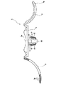
次に、本発明の実施の形態を図面と共に説明する。図1は、本発明が適用された木部用クランプ1の構成を表す正面図である。図1に示すように、この木部用クランプ1は、底面が平面状で表面に円柱面状の窪み3aが形成された基台3と、その基台3の両端に連接して円柱面状に湾曲した腕5,7と、基台3の底面を木部等に穿設された有底穴99(図3参照)に固定するためのクランプ部10とを備え、弾性を有する合成樹脂(例えば、PP,PA,PE,PS等)にて一体成形されている。
Next, embodiments of the present invention will be described with reference to the drawings. FIG. 1 is a front view illustrating a configuration of a xylem clamp 1 to which the present invention is applied. As shown in FIG. 1, the xylem clamp 1 includes a
基台3は、平面視略長方形に形成され、腕5,7は、上記円柱面の軸に沿った対向する2辺に連接されている。腕5,7が構成する円柱面の軸も窪み3aの円柱面の軸と平行に配設されている。また、一方の腕5の内側には断面がのこぎり歯状の多数の溝5aが形成され、他方の腕7の外側には溝5aと係合する突起7aが形成されている。このため、基台3の窪み3aに図示しない電線束を載置し、腕7,5を順次その電線束に覆い被せるように折り曲げ、突起7aを適宜の溝5aと係合させれば、基台3上に上記電線束を固定することができる。
The
次に、図2(A)は、本実施の形態の特徴部分であるクランプ部10の構成を表す拡大図、図2(B)はそのバネ部13の構成を表す下面図である。図1及び図2(A)に示すように、クランプ部10は、基台3の底面から垂直に突出した脚部11と、その脚部11の先端から外周方向に突出し、脚部11の基端方向に傾斜したバネ部13とを備えている。なお、バネ部13は、脚部11の中心軸に対称に一対設けられている。
Next, FIG. 2A is an enlarged view showing the configuration of the
また、バネ部13は先端部13aが他部13bより厚肉に形成され、その他部13bと先端部13aとの連接部13cは、脚部11と対向する側に傾斜面13dを有している。更に、先端部13aには、先端側でかつ脚部11と対向する側に、矩形の切り欠き13eが形成されている。
The
一方、脚部11の外周面には、上記傾斜面13dと対向する傾斜面15aを備えた突起15が形成されている。更に、バネ部13の外周面には、バネ部13よりも小さく平面視略扇形の突出片17が、各5個ずつ、脚部11の中心軸に垂直方向に突出して形成されている。
On the other hand, a
次に、このように構成されたクランプ部10の動作について、図3の模式図を用いて説明する。クランプ部10を木部等に穿設された有底穴99(本発明の穴部に相当)に挿入すると、図3(A)に示すように、突出片17が有底穴99の内壁面に押圧されて、突出片17及びバネ部13は有底穴99の開口部方向に弾性変形する。このとき、バネ部13の先端部13aは脚部11の外周面に当接し、バネ部13の傾斜面13dは突起15の傾斜面15aに当接する。
Next, operation | movement of the
このとき必要となる挿入力F1は、バネ部13及び突出片17を図3(A)の状態に変形させるための必要最小限の力に、突出片17と有底穴99の内壁面との間の摩擦抵抗を加えた大きさとなる。この状態では、突出片17を有底穴99の内壁面に圧接することにより、木部用クランプ1は有底穴99に良好に固定される。なお、切欠13e(図2参照)には、先端部13aの先端を撓み易くする効果があり、延いては、突出片17を有底穴99の開口部方向に倒れ易くして挿入力F1を一層小さくする効果がある。
The insertion force F1 required at this time is the minimum force required to deform the
次に、この状態から脚部11に抜去方向の力(離脱力F2)を加えると、図3(B)に示すように、バネ部13の先端部13aが突起15に乗り上げ、これによってバネ部13は外周方向に押圧される。すると、突出片17がバネ部13と有底穴99の内壁面とに挟まれて更に変形し、突出片17と有底穴99の内壁面との間の摩擦抵抗が極めて大きくなるため、上記挿入力F1より大きな離脱力F2を加えないとクランプ部10を有底穴99から抜去することができない。
Next, when a force in the removal direction (detachment force F2) is applied to the
このように、木部用クランプ1では、挿入力F1よりも離脱力F2を大きくすることにより、電線等の固定作業の作業性を確保しつつ良好な固定性を得ることができる。しかも、突起15の傾斜面15aによってバネ部13の傾斜面13dを押圧することによって離脱力F2を大きくしているので、径時変化の影響を受け難く耐久性に優れている。
Thus, in the clamp 1 for xylem, by making the separation force F2 larger than the insertion force F1, good fixability can be obtained while securing workability of fixing work such as electric wires. Moreover, since the detaching force F2 is increased by pressing the
なお、上記実施の形態の木部用クランプ1は、基本的には木板等の木部に穿設された有底穴99への取り付け用であるが、貫通穴にも適応でき、更に、金属板でも、若干の板厚許容はあるものの穴が空いていれば取り付けは可能である。すなわち、金属板に応用した場合、突出片17が金属板のエッジに引っ掛かることによって取り付けが可能となる。
The wood clamp 1 of the above embodiment is basically for attachment to a bottomed
また、本発明は上記実施の形態に何等限定されるものではなく、本発明の要旨を逸脱しない範囲で種々の形態で実施することができる。例えば、バネ部,突起,突出片等の形状は、上記の他にも種々に変形することができる。 In addition, the present invention is not limited to the above-described embodiment, and can be implemented in various forms without departing from the gist of the present invention. For example, the shapes of the spring portion, the protrusion, the protruding piece, and the like can be variously modified in addition to the above.
図4は、バネ部13及び突出片17の形状を異ならせた変形例としてのクランプ部20を表す正面図である。このクランプ部20のクランプ部10に対する変更点は、先端部13aに、傾斜面13dの先端と連接して外側に開くように面取り部13fを形成し、その面取り部13fより先端側のバネ部13及び突出片17を切除した点である。このように構成されたクランプ部20では、挿入力F1を一層低減し、かつ、離脱力F2を一層増加させることができる。
FIG. 4 is a front view showing a clamp portion 20 as a modified example in which the shapes of the
すなわち、挿入時には、先端部13aが脚部11に殆ど当接しないため(図5の模式図参照)、挿入力F1を一層低減することができる。また、先端部13aの先端は、面取り部13fを形成したことによってある程度内側に撓むことができる。このため、小さい有底穴99に挿入した場合にも突出片17が潰れるのを防止することができ(図5の模式図参照)、延いては、離脱力F2を一層増加させることができる。
That is, at the time of insertion, the
更に、上記各実施の形態以外の形態としては、穴部の内壁面とバネ部の外周面との間に充分な摩擦抵抗が得られる場合は、突出片を省略してバネ部の外周面を上記内壁面に直接圧接してもよく、突出片17を設ける代わりにバネ部13の外周面にギザギザの溝を形成してもよい。但し、上記のように突出片17を設けた方が、バネ部13の少なくとも先端部13aを有底穴99の同一位置に一層良好に固定することができ、離脱力F2を一層良好に大きくすることができる。
Furthermore, as a form other than the above embodiments, when sufficient frictional resistance is obtained between the inner wall surface of the hole and the outer peripheral surface of the spring part, the protruding piece is omitted and the outer peripheral surface of the spring part is used. The inner wall surface may be directly pressed, and a jagged groove may be formed on the outer peripheral surface of the
また更に、有底穴99への挿入時にも、先端部13aと脚部11との間に隙間ができるようにしてもよい。但し、上記実施の形態では、挿入時に先端部13aが脚部11の外周面に当接するので、突起15によってバネ部13を外周方向に押圧する動作が一層確実に行える。このような構成は、各部の大きさを有底穴99の大きさに合わせて設計することによってなされることはいうまでもないが、突出片17よりもバネ部13を変形し易くすれば一層設計が容易になる。すなわち、この場合、バネ部13が先に変形して先端部13aが脚部11の外周面に当接し、続いて、有底穴99の大きさに応じて突出片17が変形する。従って、突出片17よりもバネ部13を変形し易くした場合、先端部13aを脚部11の外周面に当接させた状態で木部用クランプ1を使用可能な有底穴99の直径の許容範囲が広がる。
Furthermore, a gap may be formed between the
1…木部用クランプ 3…基台 5,7…腕 10,20…クランプ部
11…脚部 13…バネ部 13a…先端部 13b…他部
13c…連接部 13d,15a…傾斜面 15…突起 17…突出片
DESCRIPTION OF SYMBOLS 1 ... Clamp for
Claims (4)
該脚部から外周方向に突出し、上記脚部の挿入時には弾性変形して上記穴部の内壁面に向けて押圧されるバネ部と、
を備えた固定具であって、
上記バネ部の先端部がそのバネ部の他部より厚肉に形成され、そのバネ部の上記先端部と上記他部との連接部が、上記バネ部の弾性変形時に上記脚部と対向する側に傾斜面を有し、
上記脚部の外周に形成され、上記バネ部の少なくとも先端部に対して上記脚部が抜去方向に移動するとき上記傾斜面に当接して、上記バネ部を外周方向に押圧する傾斜面を有する突起を、
備えたことを特徴とする固定具。 Legs inserted into the holes,
A spring portion protruding from the leg portion in the outer peripheral direction and elastically deformed when the leg portion is inserted and pressed toward the inner wall surface of the hole portion;
A fixing device comprising:
The tip part of the spring part is formed thicker than the other part of the spring part, and the connecting part between the tip part of the spring part and the other part faces the leg part when the spring part is elastically deformed. Has an inclined surface on the side,
Formed on the outer periphery of the leg portion, and having an inclined surface that abuts the inclined surface when the leg portion moves in the removal direction with respect to at least the distal end portion of the spring portion and presses the spring portion in the outer peripheral direction. The protrusion,
A fixture characterized by comprising.
上記突出片が、上記抜去方向に対して略直角に突出したことを特徴とする請求項2記載の固定具。 The spring part protrudes from the vicinity of the tip of the leg part in an inclined manner in the direction of extraction of the leg part,
The fixture according to claim 2, wherein the protruding piece protrudes substantially perpendicular to the removal direction.
Priority Applications (1)
| Application Number | Priority Date | Filing Date | Title |
|---|---|---|---|
| JP2003307279A JP4261293B2 (en) | 2003-08-29 | 2003-08-29 | Fixture |
Applications Claiming Priority (1)
| Application Number | Priority Date | Filing Date | Title |
|---|---|---|---|
| JP2003307279A JP4261293B2 (en) | 2003-08-29 | 2003-08-29 | Fixture |
Publications (2)
| Publication Number | Publication Date |
|---|---|
| JP2005076740A JP2005076740A (en) | 2005-03-24 |
| JP4261293B2 true JP4261293B2 (en) | 2009-04-30 |
Family
ID=34410111
Family Applications (1)
| Application Number | Title | Priority Date | Filing Date |
|---|---|---|---|
| JP2003307279A Expired - Lifetime JP4261293B2 (en) | 2003-08-29 | 2003-08-29 | Fixture |
Country Status (1)
| Country | Link |
|---|---|
| JP (1) | JP4261293B2 (en) |
Families Citing this family (2)
| Publication number | Priority date | Publication date | Assignee | Title |
|---|---|---|---|---|
| JP5955690B2 (en) * | 2012-08-02 | 2016-07-20 | 株式会社ニフコ | Plastic plug body |
| JP7046353B2 (en) * | 2018-03-01 | 2022-04-04 | 竹内工業株式会社 | Fastener structure |
-
2003
- 2003-08-29 JP JP2003307279A patent/JP4261293B2/en not_active Expired - Lifetime
Also Published As
| Publication number | Publication date |
|---|---|
| JP2005076740A (en) | 2005-03-24 |
Similar Documents
| Publication | Publication Date | Title |
|---|---|---|
| US20080050947A1 (en) | Double-ended press-fit connector | |
| US7241159B1 (en) | Fixing/grounding unit for electronic card | |
| JP2011096606A (en) | Pogo pin type pressure-contact connector | |
| JP2007234335A (en) | Fixing member and assembly structure of fixing member | |
| WO2016084571A1 (en) | Connection terminal | |
| JP2004055463A (en) | Connector | |
| JP2004055463A5 (en) | ||
| JP2003257524A (en) | Electric connector | |
| JP4291341B2 (en) | Connected device | |
| JP2005285654A (en) | Connector fixing member and connector using it | |
| JP2017059362A (en) | socket | |
| JP2007258028A (en) | Connector | |
| JP4261293B2 (en) | Fixture | |
| JP4558406B2 (en) | Plug contact for printed circuit boards | |
| JP2006211741A (en) | Fixing clamp | |
| KR100539621B1 (en) | Connector suitable for connecting a pair of circuit boards arranged in parallel | |
| JP4765855B2 (en) | Switch device | |
| JP2018041534A (en) | Switch device | |
| JP6293715B2 (en) | Terminal block and method for manufacturing terminal block | |
| JP2019016664A (en) | Electronic circuit device | |
| JP5845468B2 (en) | Terminal equipment | |
| JP2003068419A (en) | Connector for substrate, and jig for terminal press- fitting of connector for substrates | |
| KR200308302Y1 (en) | Fixing structure for magnet clip using of motor yoke form | |
| JP4348314B2 (en) | connector | |
| JP4366302B2 (en) | Attachment body and screw fixing member |
Legal Events
| Date | Code | Title | Description |
|---|---|---|---|
| A621 | Written request for application examination |
Free format text: JAPANESE INTERMEDIATE CODE: A621 Effective date: 20051107 |
|
| A977 | Report on retrieval |
Free format text: JAPANESE INTERMEDIATE CODE: A971007 Effective date: 20080724 |
|
| A131 | Notification of reasons for refusal |
Free format text: JAPANESE INTERMEDIATE CODE: A131 Effective date: 20080805 |
|
| A521 | Request for written amendment filed |
Free format text: JAPANESE INTERMEDIATE CODE: A523 Effective date: 20081003 |
|
| TRDD | Decision of grant or rejection written | ||
| A01 | Written decision to grant a patent or to grant a registration (utility model) |
Free format text: JAPANESE INTERMEDIATE CODE: A01 Effective date: 20090127 |
|
| A01 | Written decision to grant a patent or to grant a registration (utility model) |
Free format text: JAPANESE INTERMEDIATE CODE: A01 |
|
| A61 | First payment of annual fees (during grant procedure) |
Free format text: JAPANESE INTERMEDIATE CODE: A61 Effective date: 20090205 |
|
| FPAY | Renewal fee payment (event date is renewal date of database) |
Free format text: PAYMENT UNTIL: 20120220 Year of fee payment: 3 |
|
| R150 | Certificate of patent or registration of utility model |
Ref document number: 4261293 Country of ref document: JP Free format text: JAPANESE INTERMEDIATE CODE: R150 Free format text: JAPANESE INTERMEDIATE CODE: R150 |
|
| FPAY | Renewal fee payment (event date is renewal date of database) |
Free format text: PAYMENT UNTIL: 20120220 Year of fee payment: 3 |
|
| FPAY | Renewal fee payment (event date is renewal date of database) |
Free format text: PAYMENT UNTIL: 20120220 Year of fee payment: 3 |
|
| FPAY | Renewal fee payment (event date is renewal date of database) |
Free format text: PAYMENT UNTIL: 20120220 Year of fee payment: 3 |
|
| FPAY | Renewal fee payment (event date is renewal date of database) |
Free format text: PAYMENT UNTIL: 20130220 Year of fee payment: 4 |
|
| R250 | Receipt of annual fees |
Free format text: JAPANESE INTERMEDIATE CODE: R250 |
|
| FPAY | Renewal fee payment (event date is renewal date of database) |
Free format text: PAYMENT UNTIL: 20130220 Year of fee payment: 4 |
|
| FPAY | Renewal fee payment (event date is renewal date of database) |
Free format text: PAYMENT UNTIL: 20130220 Year of fee payment: 4 |
|
| FPAY | Renewal fee payment (event date is renewal date of database) |
Free format text: PAYMENT UNTIL: 20130220 Year of fee payment: 4 |
|
| FPAY | Renewal fee payment (event date is renewal date of database) |
Free format text: PAYMENT UNTIL: 20140220 Year of fee payment: 5 |
|
| R250 | Receipt of annual fees |
Free format text: JAPANESE INTERMEDIATE CODE: R250 |
|
| S531 | Written request for registration of change of domicile |
Free format text: JAPANESE INTERMEDIATE CODE: R313531 |
|
| R350 | Written notification of registration of transfer |
Free format text: JAPANESE INTERMEDIATE CODE: R350 |
|
| R250 | Receipt of annual fees |
Free format text: JAPANESE INTERMEDIATE CODE: R250 |
|
| R250 | Receipt of annual fees |
Free format text: JAPANESE INTERMEDIATE CODE: R250 |
|
| R250 | Receipt of annual fees |
Free format text: JAPANESE INTERMEDIATE CODE: R250 |
|
| R250 | Receipt of annual fees |
Free format text: JAPANESE INTERMEDIATE CODE: R250 |
|
| R250 | Receipt of annual fees |
Free format text: JAPANESE INTERMEDIATE CODE: R250 |
|
| R250 | Receipt of annual fees |
Free format text: JAPANESE INTERMEDIATE CODE: R250 |
|
| R250 | Receipt of annual fees |
Free format text: JAPANESE INTERMEDIATE CODE: R250 |
|
| R250 | Receipt of annual fees |
Free format text: JAPANESE INTERMEDIATE CODE: R250 |
|
| R250 | Receipt of annual fees |
Free format text: JAPANESE INTERMEDIATE CODE: R250 |
|
| R250 | Receipt of annual fees |
Free format text: JAPANESE INTERMEDIATE CODE: R250 |
|
| EXPY | Cancellation because of completion of term |