JP4260743B2 - Fluid pressure valve actuator for reciprocating engine - Google Patents

Fluid pressure valve actuator for reciprocating engine Download PDF

Info

Publication number
JP4260743B2
JP4260743B2 JP2004523855A JP2004523855A JP4260743B2 JP 4260743 B2 JP4260743 B2 JP 4260743B2 JP 2004523855 A JP2004523855 A JP 2004523855A JP 2004523855 A JP2004523855 A JP 2004523855A JP 4260743 B2 JP4260743 B2 JP 4260743B2
Authority
JP
Japan
Prior art keywords
valve
fluid pressure
selector
plug
rotor
Prior art date
Legal status (The legal status is an assumption and is not a legal conclusion. Google has not performed a legal analysis and makes no representation as to the accuracy of the status listed.)
Expired - Fee Related
Application number
JP2004523855A
Other languages
Japanese (ja)
Other versions
JP2005533962A (en
Inventor
ラビー,ヴィアニー
Current Assignee (The listed assignees may be inaccurate. Google has not performed a legal analysis and makes no representation or warranty as to the accuracy of the list.)
Individual
Original Assignee
Individual
Priority date (The priority date is an assumption and is not a legal conclusion. Google has not performed a legal analysis and makes no representation as to the accuracy of the date listed.)
Filing date
Publication date
Application filed by Individual filed Critical Individual
Publication of JP2005533962A publication Critical patent/JP2005533962A/en
Application granted granted Critical
Publication of JP4260743B2 publication Critical patent/JP4260743B2/en
Anticipated expiration legal-status Critical
Expired - Fee Related legal-status Critical Current

Links

Images

Classifications

    • FMECHANICAL ENGINEERING; LIGHTING; HEATING; WEAPONS; BLASTING
    • F01MACHINES OR ENGINES IN GENERAL; ENGINE PLANTS IN GENERAL; STEAM ENGINES
    • F01LCYCLICALLY OPERATING VALVES FOR MACHINES OR ENGINES
    • F01L1/00Valve-gear or valve arrangements, e.g. lift-valve gear
    • F01L1/02Valve drive
    • F01L1/04Valve drive by means of cams, camshafts, cam discs, eccentrics or the like
    • F01L1/047Camshafts
    • FMECHANICAL ENGINEERING; LIGHTING; HEATING; WEAPONS; BLASTING
    • F01MACHINES OR ENGINES IN GENERAL; ENGINE PLANTS IN GENERAL; STEAM ENGINES
    • F01LCYCLICALLY OPERATING VALVES FOR MACHINES OR ENGINES
    • F01L1/00Valve-gear or valve arrangements, e.g. lift-valve gear
    • F01L1/34Valve-gear or valve arrangements, e.g. lift-valve gear characterised by the provision of means for changing the timing of the valves without changing the duration of opening and without affecting the magnitude of the valve lift
    • FMECHANICAL ENGINEERING; LIGHTING; HEATING; WEAPONS; BLASTING
    • F01MACHINES OR ENGINES IN GENERAL; ENGINE PLANTS IN GENERAL; STEAM ENGINES
    • F01LCYCLICALLY OPERATING VALVES FOR MACHINES OR ENGINES
    • F01L9/00Valve-gear or valve arrangements actuated non-mechanically
    • F01L9/10Valve-gear or valve arrangements actuated non-mechanically by fluid means, e.g. hydraulic
    • FMECHANICAL ENGINEERING; LIGHTING; HEATING; WEAPONS; BLASTING
    • F01MACHINES OR ENGINES IN GENERAL; ENGINE PLANTS IN GENERAL; STEAM ENGINES
    • F01LCYCLICALLY OPERATING VALVES FOR MACHINES OR ENGINES
    • F01L1/00Valve-gear or valve arrangements, e.g. lift-valve gear
    • F01L1/02Valve drive
    • F01L1/024Belt drive
    • FMECHANICAL ENGINEERING; LIGHTING; HEATING; WEAPONS; BLASTING
    • F01MACHINES OR ENGINES IN GENERAL; ENGINE PLANTS IN GENERAL; STEAM ENGINES
    • F01LCYCLICALLY OPERATING VALVES FOR MACHINES OR ENGINES
    • F01L1/00Valve-gear or valve arrangements, e.g. lift-valve gear
    • F01L1/02Valve drive
    • F01L1/04Valve drive by means of cams, camshafts, cam discs, eccentrics or the like
    • F01L1/047Camshafts
    • F01L2001/0471Assembled camshafts
    • F01L2001/0473Composite camshafts, e.g. with cams or cam sleeve being able to move relative to the inner camshaft or a cam adjusting rod
    • FMECHANICAL ENGINEERING; LIGHTING; HEATING; WEAPONS; BLASTING
    • F01MACHINES OR ENGINES IN GENERAL; ENGINE PLANTS IN GENERAL; STEAM ENGINES
    • F01LCYCLICALLY OPERATING VALVES FOR MACHINES OR ENGINES
    • F01L1/00Valve-gear or valve arrangements, e.g. lift-valve gear
    • F01L1/02Valve drive
    • F01L1/04Valve drive by means of cams, camshafts, cam discs, eccentrics or the like
    • F01L1/047Camshafts
    • F01L1/053Camshafts overhead type
    • F01L2001/0535Single overhead camshafts [SOHC]
    • FMECHANICAL ENGINEERING; LIGHTING; HEATING; WEAPONS; BLASTING
    • F01MACHINES OR ENGINES IN GENERAL; ENGINE PLANTS IN GENERAL; STEAM ENGINES
    • F01LCYCLICALLY OPERATING VALVES FOR MACHINES OR ENGINES
    • F01L9/00Valve-gear or valve arrangements actuated non-mechanically
    • F01L9/20Valve-gear or valve arrangements actuated non-mechanically by electric means
    • F01L9/21Valve-gear or valve arrangements actuated non-mechanically by electric means actuated by solenoids
    • F01L2009/2125Shaft and armature construction
    • F01L2009/2126Arrangements for amplifying the armature stroke
    • FMECHANICAL ENGINEERING; LIGHTING; HEATING; WEAPONS; BLASTING
    • F01MACHINES OR ENGINES IN GENERAL; ENGINE PLANTS IN GENERAL; STEAM ENGINES
    • F01LCYCLICALLY OPERATING VALVES FOR MACHINES OR ENGINES
    • F01L13/00Modifications of valve-gear to facilitate reversing, braking, starting, changing compression ratio, or other specific operations
    • F01L13/0015Modifications of valve-gear to facilitate reversing, braking, starting, changing compression ratio, or other specific operations for optimising engine performances by modifying valve lift according to various working parameters, e.g. rotational speed, load, torque
    • F01L13/0036Modifications of valve-gear to facilitate reversing, braking, starting, changing compression ratio, or other specific operations for optimising engine performances by modifying valve lift according to various working parameters, e.g. rotational speed, load, torque the valves being driven by two or more cams with different shape, size or timing or a single cam profiled in axial and radial direction
    • F01L2013/0052Modifications of valve-gear to facilitate reversing, braking, starting, changing compression ratio, or other specific operations for optimising engine performances by modifying valve lift according to various working parameters, e.g. rotational speed, load, torque the valves being driven by two or more cams with different shape, size or timing or a single cam profiled in axial and radial direction with cams provided on an axially slidable sleeve
    • FMECHANICAL ENGINEERING; LIGHTING; HEATING; WEAPONS; BLASTING
    • F02COMBUSTION ENGINES; HOT-GAS OR COMBUSTION-PRODUCT ENGINE PLANTS
    • F02MSUPPLYING COMBUSTION ENGINES IN GENERAL WITH COMBUSTIBLE MIXTURES OR CONSTITUENTS THEREOF
    • F02M59/00Pumps specially adapted for fuel-injection and not provided for in groups F02M39/00 -F02M57/00, e.g. rotary cylinder-block type of pumps
    • F02M59/02Pumps specially adapted for fuel-injection and not provided for in groups F02M39/00 -F02M57/00, e.g. rotary cylinder-block type of pumps of reciprocating-piston or reciprocating-cylinder type
    • F02M59/04Pumps specially adapted for fuel-injection and not provided for in groups F02M39/00 -F02M57/00, e.g. rotary cylinder-block type of pumps of reciprocating-piston or reciprocating-cylinder type characterised by special arrangement of cylinders with respect to piston-driving shaft, e.g. arranged parallel to that shaft or swash-plate type pumps
    • F02M59/06Pumps specially adapted for fuel-injection and not provided for in groups F02M39/00 -F02M57/00, e.g. rotary cylinder-block type of pumps of reciprocating-piston or reciprocating-cylinder type characterised by special arrangement of cylinders with respect to piston-driving shaft, e.g. arranged parallel to that shaft or swash-plate type pumps with cylinders arranged radially to driving shaft, e.g. in V or star arrangement

Abstract

A hydraulic valve actuator for reciprocating engine includes at least a hydraulic cylinder ( 3 ) for opening at least one valve ( 2 ) via at least one valve opening selector ( 11 ) with at least one hydraulic positive displacement pump ( 4 ) whereof the hydraulic fluid supplied at the output can be forced into a high pressure circuit ( 10 ) by at least one pump outlet closure ( 8 ), the valve ( 2 ) capable of being maintained opened by an opening non-return valve ( 24 ), then of being reseated by a valve closing selector ( 25 ) which directs the hydraulic fluid contained in the hydraulic cylinder ( 3 ) in the hydraulic positive displacement pump ( 4 ) input by co-operating with a pump input non-return valve ( 26 ).

Description

本発明はレシプロエンジンの弁のリフト、開放進角及び/又は閉鎖遅角を制御することを可能にする流体圧アクチュエータに関する。   The present invention relates to a hydraulic actuator that makes it possible to control the valve lift, opening advancement and / or closing delay of a reciprocating engine.

現時点では、クランク軸の回転角の関数としてのレシプロエンジンの弁の開放点は前記クランク軸に関するクランク軸の角位相により定められる。弁の開放時間とリフトはカム形状により定められる。一般的には、また自動車産業により現在生産される大部分のエンジンにおいては、これらの特色は固定されている。   At present, the reciprocating engine valve opening point as a function of crankshaft rotation angle is determined by the crankshaft angular phase relative to the crankshaft. The opening time and lift of the valve are determined by the cam shape. In general, and in most engines currently produced by the automotive industry, these features are fixed.

自動車に使用されるレシプロ内燃エンジンの弁の開放点、開放時間及びリフトといったパラメータを制御することの有用性が経験により明らかにされてきた。正確には、これらのパラメータはシリンダの充填及び燃焼条件に大きな効果を有し、動作中にそれらを制御することによりエンジンの回転速度及び所望の負荷の関数として効率と出力を最適化し、排出物質を制御することが可能になる。   Experience has shown the usefulness of controlling parameters such as the opening point, opening time and lift of valves in reciprocating internal combustion engines used in automobiles. Precisely, these parameters have a significant effect on cylinder filling and combustion conditions, and controlling them during operation optimizes efficiency and power output as a function of engine speed and desired load, and emissions Can be controlled.

これらのパラメータの制御は特に以下のことを可能にする。即ち、
−特に吸気及び排気マニホルドにおけるガスの慣性を考慮して、シリンダの最大充填に最も適した瞬間に吸気及び/又は排気弁を開閉させることにより全ての回転速度において高トルクを得ること。
−低回転速度においてエンジンのトルクとフレキシビリティーを損なうことなく最高の出力を得ること。
−吸気弁のリフト及び/又は開放時点に作用し、それによりエンジンの効率を損なうポンプ損失を抑えることにより、絞り弁を用いないで、直接弁における弁調節によりシリンダに導入される給気を調節すること。
−特に弁リフト高さを制御し、それによりシリンダに導入されるガスの速度を制御可能にし、それにより、空燃混合と燃焼速度の均一性を制御することにより、燃焼室内の乱流のよりよい制御を得ること。
−特に、(吸気及び排気弁が同一シリンダ内で同時に開いているときに)弁の相互作用の大小を選択し、それにより排出物質と効率のより大きい制御を可能にし、より小さいサイクルバラツキ(燃焼不規則性、点火不良)を得ることを可能にし、それによりエンジンのアイドリング速度を低下することにより、シリンダに導入される給気中の薄められた燃焼ガスの比率を調節すること。
Control of these parameters in particular makes it possible to: That is,
Obtaining high torque at all rotational speeds by opening and closing the intake and / or exhaust valves at the moment most suitable for maximum cylinder filling, especially considering the inertia of the gas in the intake and exhaust manifolds.
-Obtaining the highest output without compromising engine torque and flexibility at low speeds.
-Regulates the intake air introduced into the cylinder by adjusting the valve directly without using the throttle valve by controlling the pump loss which affects the lift and / or opening time of the intake valve and thereby impairs the engine efficiency To do.
-More specifically, the valve lift height can be controlled, thereby controlling the speed of the gas introduced into the cylinder, thereby controlling the air-fuel mixing and the uniformity of the combustion speed, thereby reducing the turbulence in the combustion chamber. Getting good control.
-In particular, select the magnitude of the valve interaction (when the intake and exhaust valves are open simultaneously in the same cylinder), thereby allowing greater control of emissions and efficiency, and smaller cycle variations (combustion) Irregularity, poor ignition), thereby reducing the engine idling speed, thereby adjusting the ratio of diluted combustion gas in the charge air introduced into the cylinder.

更に、「閉鎖遅角吸気」の制御は逆流により、言い換えれば、余分な新たな吸気ガスを吸気マニホルドに戻すことにより、シリンダに導入される給気を調節することを可能にする。この技術は、部分負荷の下でオット−ボ・ドゥ・ローシャ・サイクル(Otto or Beau de Rochas cycle)より高効率を有するアトキンソン・サイクル(Atkinson Cycle)を採用することを可能にするので、可変圧縮比を有するエンジンにおいてその最大性能を発揮する。   Furthermore, the control of “closed retarded intake” makes it possible to adjust the supply air introduced into the cylinder by backflow, in other words by returning excess new intake gas to the intake manifold. This technology makes it possible to employ the Atkinson Cycle, which is more efficient than the Otto or Beau de Rochas cycle under partial loads, so variable compression The maximum performance is exhibited in an engine having a ratio.

固定圧縮比を有する大気圧又は過給機付エンジンにおいて、「閉鎖遅角吸気」の制御により得られる逆流は実際の圧縮工程を制御し、それにより部分負荷の下に、より高効率を可能にするより高圧縮比を提供することを可能にし、全ての回転速度におけるノッキングと効率のよりよい制御を可能にする。   In an atmospheric or supercharged engine with a fixed compression ratio, the backflow obtained by controlling “closed retarded intake” controls the actual compression process, thereby enabling higher efficiency under partial loads Allows a higher compression ratio to be provided and allows better control of knocking and efficiency at all rotational speeds.

可変圧縮比エンジンにおいて、リフトの制御は、圧縮比が高いときに部分負荷の下で弁のより低いリフトを可能にすることによりピストンにおける弁のラップ深さ(ピストン上に弁の形状が落とす影)を抑えることを可能にする。   In variable compression ratio engines, lift control is achieved by allowing valve lower lift under partial load when the compression ratio is high, thereby allowing valve wrap depth in the piston (the effect of the valve shape to drop on the piston). ).

レシプロ内燃エンジンにおいて弁の開放進角、開放時間及びリフトといったこれらのパラメータの全て又はいくつかを制御することを可能にする種々の技術、即ち、工業化されている簡単なカム軸位相シフタから前記パラメータの全ての制御を可能にする電気機械又は電気流体圧装置まであるが、後者は高コスト、信頼性、制御性又は過大なエネルギー消費の点から大きな欠点を有するのでまだ実験段階にある。   The various parameters that make it possible to control all or some of these parameters such as valve opening angle, opening time and lift in a reciprocating internal combustion engine, i.e. from industrially simple camshaft phase shifters said parameters However, the latter is still in the experimental stage because it has major drawbacks in terms of cost, reliability, controllability or excessive energy consumption.

種々のカム軸位相シフタとリフト制御装置が大きい系列製品として販売されているが、それらは高価で制御性に限界があり、複数の所定の位置又は連続可変を有する簡単な位相シフタは弁の開放進角と閉鎖遅角を独立に制御することが不可能であり、従って、開放時間を制御することができない。更にそれらはリフトを制御することができない。商品名「Honda」の「VTec」又は「Porsche」の「Variocam Plus」で知られる装置のようないくつかの装置はエンジンの動作状態の関数として吸気弁のリフトの二つの異なる法則を選択することを可能にする二つの異なるカム外形を備えている。   Various camshaft phase shifters and lift control devices are sold as large series products, but they are expensive and have limited controllability, and simple phase shifters with multiple predetermined positions or continuously variable open valve It is impossible to control the advance angle and the closing delay angle independently, and therefore it is not possible to control the opening time. Furthermore, they cannot control the lift. Some devices, such as the device known under the trade name “Honda” “VTec” or “Porsche” “Variocam Plus”, select two different laws of intake valve lift as a function of engine operating conditions. It has two different cam profiles that make it possible.

現時点で販売されている最も手の込んだ装置はおそらく「BMW」により開発された商品名「Valvetronic」で知られる装置であり、これは弁のリフトを制御することを可能にし、カム軸の位相シフト用の「Vanos」に連結されて実質的に全てのパラメータを調節することができるが、例外は、開放進角の設定に連結されたままの閉鎖遅角の設定であり、これにより弁の開放時間の制御を妨げている。   The most elaborate device sold at the moment is probably the device developed under the trade name “Valvetronic” developed by “BMW”, which makes it possible to control the lift of the valve and the phase of the camshaft. Linked to the “Vanos” for shifting, virtually all parameters can be adjusted, with the exception of the closed retard setting which remains linked to the open advance setting, which Preventing control of the opening time.

電磁タイプの電磁アクチュエータは現時点で最良レベルのパラメータ化を有するが、顕著な欠陥がそれらの工業化を困難にしており、これらは過度のエネルギー消費、高回転速度での弁のうなり、弁が弁座に休止している間の連続性の欠如、それらの電気部品の過熱又は車両に対して通常発生される電圧より高い供給電圧を与える必要性を含む。更に、それらの製造コストが高く、それらの信頼性を車両の有効寿命に渡って保証することが困難である。   Although electromagnetic type electromagnetic actuators currently have the best level of parameterization, significant defects have made their industrialization difficult, these are excessive energy consumption, high-speed valve beats, Including the lack of continuity during sleep, the overheating of their electrical components, or the need to provide a supply voltage higher than that normally generated for the vehicle. Furthermore, their manufacturing costs are high and it is difficult to guarantee their reliability over the useful life of the vehicle.

「Siemens」と協同で米国において「Sturman」により構築された特に低回転速度を有するエンジン用として意図された装置のような電気流体圧装置も開発されてきた。   Electrohydraulic devices have also been developed in cooperation with “Siemens”, such as devices designed in the United States by “Sturman”, especially for engines with low rotational speeds.

電磁アクチュエータにしろ、電気流体圧アクチュエータにしろ、これらの装置は高エネルギー消費という欠点を有し、従って、エンジン効率の改善の点からそれらの有用性を減じている。   Whether electromagnetic or electrohydraulic actuators, these devices have the disadvantage of high energy consumption, thus reducing their usefulness in terms of improving engine efficiency.

同時に、簡単で、信頼性があって、エネルギーの点で経済的で、工業化が容易で、複雑でなく、レシプロ内燃エンジンの弁の開放進角、閉鎖遅角及びリフトの独立制御を可能にする技術は今日存在しない。   At the same time, simple, reliable, economical in terms of energy, easy to industrialize, uncomplicated, and allows independent control of the reciprocating internal combustion engine valve opening advance, closing delay and lift. Technology does not exist today.

自動車エンジン産業のためにそのような技術が入手不可能であることに応えるために、本発明による装置は特定の実施例に従って以下のことができる。即ち、
・弁の開放進角の独立制御、
・弁の閉鎖遅角の独立制御、
・弁のリフトの独立制御、
・静かで省エネルギーの作動
である。
In order to respond to the unavailability of such technology for the automotive engine industry, the device according to the invention can: That is,
・ Independent control of valve opening angle,
・ Independent control of valve closing delay,
・ Independent control of valve lift,
-Quiet and energy-saving operation.

従って、本発明による装置は弁の開放進角、開放時間及びリフトの制御により出力、効率及び排出物質の制御における改良策の本質的部分を実施することを可能にする。更に、本発明による装置は自動車産業の要求に適合した信頼性レベル及び生産コストを有する。   The device according to the invention thus makes it possible to implement an essential part of the improvement in the control of power, efficiency and emissions by controlling the opening angle, opening time and lift of the valve. Furthermore, the device according to the invention has a level of reliability and production costs adapted to the requirements of the automotive industry.

本発明による装置は以下の点において先行技術による弁駆動装置とは区別される。即ち、
a)クランク軸がなく、如何なる揺動体もない。
b)特に、通常は軸受とそれらの潤滑装置により具現化されるカム軸線の除去により、また弁タペットの穴の除去によりシリンダヘッドが簡略化される。
c)特定の実施例によれば、カム軸の除去によりエンジンの縦の大きさが減少される。
d)特に、タペット及び/又は揺動体の除去により弁とそれらの駆動装置から成るアセンブリーの大きさが低減され、従って弁の開閉中のアセンブリーの加減速に必要な力が減少する。
e)調整ワッシャ、調整ネジ又は流体圧タペット等のカムとタペットの間の遊びを設定する装置が除去される。
f)シリンダヘッド内の弁の方向付けが容易になる。
The device according to the invention is distinguished from prior art valve drives in the following respects. That is,
a) There is no crankshaft and no swinging body.
b) In particular, the cylinder head is simplified by the removal of camshafts, which are usually embodied by bearings and their lubrication devices, and by the removal of valve tappet holes.
c) According to a particular embodiment, the vertical size of the engine is reduced by the removal of the camshaft.
d) In particular, the removal of the tappet and / or the rocking body reduces the size of the assembly comprising the valves and their drive, thus reducing the force required to accelerate and decelerate the assembly during opening and closing of the valve.
e) A device for setting play between the cam and the tappet, such as an adjustment washer, adjustment screw or hydraulic tappet is removed.
f) Orientation of the valve in the cylinder head is facilitated.

従って、本発明によるレシプロエンジン用流体圧弁アクチュエータは、
◆ダクトにより高圧流体圧回路に接続され、少なくとも一つの弁の開放を確実にする少なくとも一つの流体圧ジャッキと、
◆少なくとも一つの吐出口と、少なくとも一つの吸入口とを備える少なくとも一つの流体圧容積式ポンプであって、その回転速度がエンジンのクランク軸の回転速度に比例するポンプと、
◆流体圧容積式ポンプの吐出口に吐出された流体圧流体が低圧回路又はタンクに噴出しないように、また一つ以上の弁の開放を確実にする一つ以上の流体圧ジャッキと連通する高圧回路に向けることができる少なくとも一つのポンプ吐出口プラグと、
◆高圧回路を介して、流体圧容積式ポンプの吐出口において吐出された流体圧流体を少なくとも一つの弁の流体圧ジャッキに向けて弁を開くことを可能にし、それと同時に前記流体圧流体が一つ以上の他の弁に向けられないようにしてその弁を閉じたままにする少なくとも一つの弁開放セレクタと、
◆ポンプ吐出口と少なくとも一つの弁の流体圧ジャッキの間の高圧回路に配置され、弁を開放し続けるために前記弁の前記流体圧ジャッキ内に流体圧流体を保持することを可能にする少なくとも一つの開放逆止弁と、
◆開放逆止弁により開放され続ける少なくとも一つの弁の流体圧ジャッキに容れられた流体圧流体を流体圧容積式ポンプの吸入口に向け、それにより、前記弁を確実に閉鎖させ、かつそれらの流体圧ジャッキに容れられた流体圧流体が他の弁の流体圧ジャッキに導入されないようにしてその弁を閉じた位置に維持することを可能にする少なくとも一つの弁閉鎖セレクタと、
◆低圧回路又はタンクの圧力が流体圧容積式ポンプの吸入口の圧力より高いときに前記低圧回路又は前記タンクの流体圧流体が流体圧容積式ポンプの前記吸入口に入ることを可能にする少なくとも一つのポンプ吸入口逆止弁と
を備える。
Therefore, the hydraulic valve actuator for a reciprocating engine according to the present invention is
◆ at least one fluid pressure jack connected to the high pressure fluid pressure circuit by a duct to ensure the opening of at least one valve;
A pump having at least one discharge port and at least one suction port, the pump having a rotational speed proportional to a rotational speed of an engine crankshaft;
◆ High pressure communicating with one or more fluid pressure jacks to ensure that the fluid pressure fluid discharged to the discharge port of the fluid pressure positive displacement pump does not spout into the low pressure circuit or tank and to ensure the opening of one or more valves At least one pump outlet plug that can be directed to the circuit;
It is possible to open the valve by directing the fluid pressure fluid discharged at the discharge port of the fluid pressure positive displacement pump to the fluid pressure jack of at least one valve via the high pressure circuit, and at the same time the fluid pressure fluid At least one valve open selector that keeps the valve closed without being directed to one or more other valves;
◆ arranged in a high pressure circuit between the pump outlet and the hydraulic jack of at least one valve, at least allowing to hold hydraulic fluid in the hydraulic jack of the valve to keep the valve open One open check valve,
The fluid pressure fluid contained in the fluid pressure jack of at least one valve that is kept open by the open check valve is directed to the inlet of the fluid displacement pump, thereby ensuring that the valve is closed and At least one valve closure selector that allows the hydraulic fluid contained in the hydraulic jack to be prevented from being introduced into the hydraulic jacks of other valves and to maintain that valve in a closed position;
At least allowing the fluid pressure fluid in the low pressure circuit or tank to enter the suction port of the fluid displacement pump when the pressure in the low pressure circuit or tank is higher than the pressure of the suction port of the fluid displacement pump One pump inlet check valve.

本発明の他の本質的な特色は本明細書及び独立請求項に直接又は間接的に従属する従属請求項に記述した。   Other essential features of the invention are set out in the dependent claims which depend directly or indirectly on the specification and the independent claims.

本発明によるレシプロエンジン用流体圧弁アクチュエータは
◆エンジンの前記又は各弁に対する流体圧ジャッキであって、前記弁を開放させ、開放位置に保持させ、閉鎖させる流体圧ジャッキと、
◆流体圧容積式ポンプであって、その回転速度がクランク軸の回転速度に比例するポンプと、
◆種々の弁の集合を合体させる装置と
を備える。
A fluid pressure valve actuator for a reciprocating engine according to the present invention is a fluid pressure jack for the or each valve of an engine, wherein the valve is opened, held in an open position, and closed.
A fluid pressure positive displacement pump whose rotational speed is proportional to the rotational speed of the crankshaft,
◆ Equipped with a device that unites a collection of various valves.

種々の弁の集合を合体させる装置は以下の機能を有する。即ち、
−前記弁を確実にリフトさせるために、クランク軸の角度位置の関数として所望の瞬間に、流体圧容積式ポンプの吐出口に供給された流体圧流体を弁の流体圧ジャッキに向け、
−前記弁を所望の高さへ確実にリフトさせるために、所望のクランク軸の回転度数の間、流体圧容積式ポンプの吐出口に供給された流体圧流体を弁の流体圧ジャッキに向け、
−所望のクランク軸の回転度数の間、前記弁の開放を維持するために、流体圧流体を弁の流体圧ジャッキ内に閉じ込めておき、
−前記弁を確実に休止させ、弁の開放中に弁の戻しバネにより蓄積されたエネルギーの一部を回収するために、クランク軸の角度位置の関数として所望の瞬間に、弁の流体圧ジャッキに容れられた流体圧流体を流体圧容積式ポンプの吸入口に向ける。
An apparatus for combining various valve sets has the following functions. That is,
To direct the hydraulic fluid supplied to the outlet of the hydraulic positive displacement pump to the hydraulic jack of the valve at a desired moment as a function of the angular position of the crankshaft to ensure that the valve is lifted;
In order to ensure that the valve is lifted to the desired height, the hydraulic fluid supplied to the outlet of the hydraulic positive displacement pump is directed to the hydraulic jack of the valve for the desired degree of crankshaft rotation;
In order to keep the valve open for the desired crankshaft rotation frequency, the hydraulic fluid is confined in the hydraulic jack of the valve;
The valve's hydraulic jack at a desired moment as a function of the angular position of the crankshaft in order to ensure that the valve is at rest and to recover some of the energy stored by the valve return spring during valve opening. The fluid pressure fluid contained in is directed to the suction port of the fluid pressure positive displacement pump.

特定の実施例によれば、本発明による装置は、
◆一つ以上のコンピュータに従い、
−クランク軸の角度位置の関数としての弁の開放点と、
−弁のリフト高さと、
−クランク軸の角度位置の関数としての弁の閉鎖点と
を制御することを可能にする一つ以上の電動機と、
◆弁リフトを測定する装置と対になって、エンジンの弁の実際の開放点と、リフト高さと、閉鎖点についてコンピュータに知らせる、クランク角を測定する装置と
を備える。前記測定装置と前記コンピュータの集合はエンジンの弁の移動に対する十分な精度を保証する制御ループを提供する。
According to a particular embodiment, the device according to the invention comprises
◆ Follow one or more computers,
The opening point of the valve as a function of the angular position of the crankshaft;
-The lift height of the valve;
One or more electric motors that make it possible to control the closing point of the valve as a function of the angular position of the crankshaft;
◆ Paired with a device that measures the valve lift, it has a device for measuring the crank angle that informs the computer about the actual opening point of the engine valve, the lift height and the closing point. The collection of the measuring device and the computer provides a control loop that guarantees sufficient accuracy for engine valve movement.

非限定的な例として与えられる添付図に関連する以下の説明は本発明と、その特色と、発明が与えることができる利点をもっと明確に理解することを可能にするであろう。   The following description in connection with the accompanying drawings given by way of non-limiting example will allow a clearer understanding of the present invention, its features and the advantages that the invention can provide.

図1乃至3及び22は、レシプロエンジン12の少なくとも一つの弁2を確実に開放させるために、ダクトにより高圧流体圧回路10に接続された少なくとも一つの流体圧ジャッキ3を備える流体圧アクチュエータ1を示す。   1 to 3 and 22 show a fluid pressure actuator 1 comprising at least one fluid pressure jack 3 connected by a duct to a high pressure fluid pressure circuit 10 in order to ensure that at least one valve 2 of the reciprocating engine 12 is opened. Show.

流体圧アクチュエータ1は、少なくとも一つの吐出口6と、少なくとも一つの吸入口7とを備える少なくとも一つの流体圧容積式ポンプ4であって、その回転速度がエンジン12のクランク軸5の回転速度に比例するポンプを備える。   The fluid pressure actuator 1 is at least one fluid pressure positive displacement pump 4 having at least one discharge port 6 and at least one suction port 7, and the rotation speed thereof is the same as the rotation speed of the crankshaft 5 of the engine 12. Proportional pumps are provided.

流体圧アクチュエータ1は、流体圧容積式ポンプ4の吐出口6に吐出された流体圧流体が低圧回路9又はタンク58に噴出しないようにし、またエンジン12の一つ以上の弁2を確実に開放させる一つ以上の流体圧ジャッキ3と連通する高圧回路10に強制的に向けることを可能にする少なくとも一つのポンプ吐出口プラグ8を備える。   The fluid pressure actuator 1 prevents the fluid pressure fluid discharged to the discharge port 6 of the fluid pressure positive displacement pump 4 from being jetted to the low pressure circuit 9 or the tank 58 and reliably opens one or more valves 2 of the engine 12. At least one pump outlet plug 8 is provided that allows it to be forcibly directed to a high pressure circuit 10 in communication with one or more fluid pressure jacks 3 to be driven.

流体圧アクチュエータ1は、高圧回路10を介して、流体圧容積式ポンプ4の吐出口6において吐出された流体圧流体を少なくとも一つの弁2の流体圧ジャッキ3に向け、弁を開放させることを可能にし、それにより、それと同時に前記流体圧流体が一つ以上の他の弁2に向けられないようにしながらその弁を閉じられたままにする少なくとも一つの弁開放セレクタ11を備える。   The fluid pressure actuator 1 directs the fluid pressure fluid discharged from the discharge port 6 of the fluid pressure positive displacement pump 4 to the fluid pressure jack 3 of at least one valve 2 via the high pressure circuit 10 and opens the valve. Comprising at least one valve opening selector 11 which enables and thereby keeps the valve closed while simultaneously preventing the hydraulic fluid from being directed to one or more other valves 2.

流体圧アクチュエータ1は、ポンプ吐出口6と少なくとも一つの弁2の流体圧ジャッキ3の間の高圧回路10に配置され、弁の開放を維持するために前記弁2の前記流体圧ジャッキ3内に流体圧流体を保持することを可能にする少なくとも一つの開放逆止弁24を備える。   A fluid pressure actuator 1 is arranged in the high pressure circuit 10 between the pump outlet 6 and the fluid pressure jack 3 of the at least one valve 2 and in the fluid pressure jack 3 of the valve 2 to keep the valve open. At least one open check valve 24 is provided that allows the hydraulic fluid to be retained.

流体圧アクチュエータ1は、開放逆止弁24により開放され続ける少なくとも一つの弁2の流体圧ジャッキ3に容れられた流体圧流体を流体圧容積式ポンプ4の吸入口7に向け、それにより、前記弁2を閉鎖させ、かつそれらの流体圧ジャッキ3に容れられた流体圧流体が他の弁2の流体圧ジャッキ3に導入されないようにしてその弁を閉じられた位置に維持することを可能にする少なくとも一つの弁閉鎖セレクタ25を備える。   The fluid pressure actuator 1 directs the fluid pressure fluid contained in the fluid pressure jack 3 of the at least one valve 2 that is kept open by the open check valve 24 to the suction port 7 of the fluid pressure positive displacement pump 4, thereby Enabling the valves 2 to be closed and kept in a closed position so that the hydraulic fluid contained in those hydraulic jacks 3 is not introduced into the hydraulic jacks 3 of the other valves 2 At least one valve closing selector 25 is provided.

流体圧アクチュエータ1は、前記低圧回路9又は前記タンク58の圧力が流体圧容積式ポンプ4の前記吸入口7の圧力より高いときに低圧回路9又はタンク58の流体圧流体が流体圧容積式ポンプ4の吸入口7に入ることを可能にする少なくとも一つのポンプ吸入口逆止弁26を備える(図8)。   When the pressure in the low pressure circuit 9 or the tank 58 is higher than the pressure in the suction port 7 of the fluid pressure positive displacement pump 4, the fluid pressure actuator 1 causes the fluid pressure fluid in the low pressure circuit 9 or the tank 58 to be a fluid pressure positive displacement pump. 4 at least one pump inlet check valve 26 allowing entry into the four inlets 7 (FIG. 8).

少なくとも一つの弁2がある瞬間における弁のリフト高さについてコンピュータに知らせる電気又は電磁信号を発する測定装置を備えることが特筆される。   It is noted that at least one valve 2 comprises a measuring device that emits an electrical or electromagnetic signal that informs the computer about the lift height of the valve at a certain moment.

低圧回路9に関し、後者はエンジン12の加圧された潤滑回路15に接続される。低圧回路9はまたエンジン12の加圧された潤滑回路15とは独立に設けられてもよい。   With respect to the low pressure circuit 9, the latter is connected to the pressurized lubrication circuit 15 of the engine 12. The low pressure circuit 9 may also be provided independently of the pressurized lubrication circuit 15 of the engine 12.

低圧回路9がエンジン12の加圧された潤滑回路15と独立であれば、後者は更なるポンプ13により大気圧より高い圧力に維持される。その場合、低圧回路9は蓄圧器14を備えてもよい。   If the low pressure circuit 9 is independent of the pressurized lubrication circuit 15 of the engine 12, the latter is maintained at a pressure above atmospheric pressure by a further pump 13. In that case, the low-pressure circuit 9 may include a pressure accumulator 14.

特定の実施例によれば、ポンプ吐出口プラグ8と弁開放セレクタ11は、流体圧容積式ポンプ4の吐出口6に接続されかつ低圧回路9に接続された吐出口か、少なくとも一つの流体圧ジャッキ3に接続された吐出口のどちらかに関連付けられる少なくとも一つの吸入口を備える一つの組み合わされた分配器81として寄せ集めることもできる(図22)。   According to a particular embodiment, the pump outlet plug 8 and the valve opening selector 11 are connected to the outlet 6 of the fluid pressure positive displacement pump 4 and connected to the low pressure circuit 9 or at least one fluid pressure. It can also be gathered together as one combined distributor 81 with at least one inlet associated with either outlet connected to the jack 3 (FIG. 22).

図4乃至7はレシプロエンジン用流体圧アクチュエータを示し、そのシリンダと、弁2を確実に開放させる流体圧ジャッキ3のチャンバ20は弁ガイド16に配置され、前記シリンダと前記チャンバ20は、弁2を開くために弁軸18に配置されたショルダ19から成るジャッキピストンと協同する。   4 to 7 show a hydraulic actuator for a reciprocating engine. The cylinder and the chamber 20 of the hydraulic jack 3 for reliably opening the valve 2 are arranged in the valve guide 16, and the cylinder and the chamber 20 are connected to the valve 2. Cooperates with a jack piston consisting of a shoulder 19 arranged on the valve stem 18 for opening.

弁軸18に配置されたショルダ19から成るジャッキピストンは弁ガイド16内での弁2のガイドに参画する。   A jack piston comprising a shoulder 19 arranged on the valve shaft 18 participates in the guide of the valve 2 in the valve guide 16.

弁軸18上のショルダ19から成るジャッキピストンは少なくとも一つのシール17を備える。   The jack piston consisting of a shoulder 19 on the valve shaft 18 is provided with at least one seal 17.

弁ガイド16は吸気又は排気ダクト21の近傍に、前記吸気又は排気ダクト21に向う流体圧流体の通路を制限するためにエンジン12のシリンダヘッドに設けられた少なくとも一つのドレーン22を備える(図5)。   The valve guide 16 is provided in the vicinity of the intake or exhaust duct 21 with at least one drain 22 provided in the cylinder head of the engine 12 to restrict the passage of fluid pressure fluid toward the intake or exhaust duct 21 (FIG. 5). ).

弁2を確実に開放させる流体圧ジャッキ3は、弁2がそれらの弁座と接触する前に弁2を制動することを可能にする限界−停止減衰装置を備える。   The hydraulic jack 3 that reliably opens the valve 2 comprises a limit-stop damping device that allows the valve 2 to brake before it contacts the valve seats.

こうして、弁ガイド16に配置された流体圧ジャッキ3は弁軸18に配置された小さいショルダ23から成る限界−停止減衰装置を備える。 Thus, the hydraulic jack 3 arranged in the valve guide 16 comprises a limit-stop damping device consisting of a small shoulder 23 arranged in the valve shaft 18.

ショルダ23は小さい高さと、前記ショルダ23より実質的に大きい直径とを有するシリンダ部と協同し、前記シリンダ部は弁ガイド16の上部に配置され、それにより、弁2が閉鎖行程の終りに到達するときに流体圧流体を剪断するが、その効果は前記弁2の速度を減ずることである。   The shoulder 23 cooperates with a cylinder part having a small height and a diameter substantially larger than the shoulder 23, the cylinder part being arranged at the top of the valve guide 16 so that the valve 2 reaches the end of the closing stroke. In doing so, the hydraulic fluid is sheared, the effect of which is to reduce the speed of the valve 2.

少なくとも一つの弁2を確実に開放させる流体圧ジャッキ3はそのチャンバ20の領域に抜き取り装置を備え、これは、前記チャンバ20内に容れられた流体圧流体が低圧回路に逃げられるようにするために命令手段により開放できるプラグから成る。   The hydraulic jack 3 that reliably opens at least one valve 2 is provided with an extraction device in the region of the chamber 20, which allows the hydraulic fluid contained in the chamber 20 to escape to the low-pressure circuit. It consists of a plug that can be opened by command means.

図8は流体圧容積式ポンプ4を示し、これはベーンポンプでもよく、そのステータは、独立な少なくとも一つの吸入口と少なくとも一つの吐出口を定める内側外形を有する。   FIG. 8 shows a hydraulic positive displacement pump 4, which may be a vane pump, whose stator has an inner profile defining at least one independent inlet and at least one outlet.

第1の変形において、流体圧容積式ポンプ4は、少なくとも二つのピニオンと、独立な少なくとも一つの吸入口と少なくとも一つの吐出口を備えるギヤポンプでもよい。   In the first modification, the hydraulic positive displacement pump 4 may be a gear pump including at least two pinions, at least one independent suction port, and at least one discharge port.

第2の変形において、流体圧容積式ポンプ4はエンジン12の所定の動作条件の下に前記エンジン12の弁2のリフト速度を変更することを可能にする可変容量ポンプでもよい。   In a second variant, the hydraulic positive displacement pump 4 may be a variable displacement pump that makes it possible to change the lift speed of the valve 2 of the engine 12 under predetermined operating conditions of the engine 12.

図11乃至13はポンプ吐出口プラグ8の実施例を図解する。   11 to 13 illustrate an embodiment of the pump outlet plug 8.

もう一つの実施例において、ポンプ吐出口プラグ8はコンピュータにより制御される電磁弁である。   In another embodiment, the pump outlet plug 8 is a computer controlled solenoid valve.

図11乃至13に示す例において、ポンプ吐出口プラグ8は、プラグハウジング65に容れられかつエンジン12のクランク軸5の速度に比例する速度で回転しかつプラグロータ27を備える回転機械装置であり、前記プラグロータは前記プラグロータ27の回転中に前記プラグハウジング65に収容された一つ以上のポンプ吐出口29を周期的に塞ぐ少なくとも一つの突起28を備える。   In the example shown in FIGS. 11 to 13, the pump outlet plug 8 is a rotary machine device that is contained in the plug housing 65 and rotates at a speed proportional to the speed of the crankshaft 5 of the engine 12 and includes the plug rotor 27. The plug rotor includes at least one protrusion 28 that periodically closes one or more pump discharge ports 29 accommodated in the plug housing 65 during the rotation of the plug rotor 27.

ポンプ吐出口29とプラグロータ27の突起28の間の耐漏洩性が、前記突起が前記ポンプ吐出口29の反対に位置するときに、前記ポンプ吐出口29と前記突起28との接触を保つ装置30により補強されることが特筆される。   An apparatus for maintaining the contact between the pump discharge port 29 and the protrusion 28 when the protrusion is positioned opposite to the pump discharge port 29 with respect to leakage resistance between the pump discharge port 29 and the protrusion 28 of the plug rotor 27. It is noted that 30 is reinforced.

接触を保つ装置30はプラグピストン31から成り、それはプラグハウジング65内で半径方向に配置されかつそれを縦方向に真っ直ぐに通っているポンプ吐出口29を備える。   The device 30 for maintaining contact consists of a plug piston 31, which comprises a pump outlet 29 which is arranged radially in the plug housing 65 and passes straight through it longitudinally.

ポンプ吐出口29はラジアルポート33によりポンプ吐出口ダクト32に接続される。プラグピストン31は突起28の半径と実質的に同一の半径を有する凹の円筒支持面を備え、それにより、前記突起28との広い接触面を有する。   The pump discharge port 29 is connected to the pump discharge port duct 32 by a radial port 33. The plug piston 31 has a concave cylindrical support surface having a radius substantially the same as the radius of the protrusion 28, thereby having a wide contact surface with the protrusion 28.

プラグピストン31はプラグハウジング65側に、突起28との接触面より大きい流体圧流体圧力を受ける表面を有し、それにより、前記突起28の通過中に流体の圧力がポンプ吐出口ダクト32において増加するときに、前記プラグピストンは前記突起と接触し続ける(図13)。   The plug piston 31 has a surface on the side of the plug housing 65 that receives fluid pressure fluid pressure larger than the contact surface with the projection 28, so that the fluid pressure increases in the pump outlet duct 32 during the passage of the projection 28. When doing so, the plug piston continues to contact the projection (FIG. 13).

プラグピストン31のポンプ吐出口29を塞ぐ突起がないときは、プラグピストンはバネ56によりプラグハウジング65に対し押し付け接触し続ける(図12)。   When there is no protrusion that closes the pump discharge port 29 of the plug piston 31, the plug piston continues to be pressed against the plug housing 65 by the spring 56 (FIG. 12).

プラグピストン31は前記プラグピストンとそれが収容される孔との間の耐漏洩性を保証する少なくとも一つのシールを備える。   The plug piston 31 is provided with at least one seal that ensures leakage resistance between the plug piston and the hole in which it is accommodated.

図11及び15乃至19はエンジン12のクランク軸5に対して角度位相シフトを行う装置を備え、それにより弁2の開放が進角又は遅角できるプラグロータ27を図解する。   FIGS. 11 and 15 to 19 illustrate a plug rotor 27 provided with a device for performing an angular phase shift with respect to the crankshaft 5 of the engine 12 so that the opening of the valve 2 can be advanced or retarded.

図解されない変形において、プラグロータ27の位相シフト装置は、前記ロータの内側に配置されかつ前記プラグロータの駆動軸の外側に配置された少なくとも一つの螺旋状溝と協同する少なくとも一つの螺旋状溝から成る。   In a variant that is not illustrated, the phase shift device of the plug rotor 27 comprises at least one helical groove arranged inside the rotor and cooperating with at least one helical groove arranged outside the drive shaft of the plug rotor. Become.

この変形において、位相シフトはフォークによるプラグロータ27のその回転軸に平行な並進により行われる。   In this variant, the phase shift is effected by translation of the plug rotor 27 by a fork parallel to its rotational axis.

この変形によれば、プラグロータ27はプラグハウジング65内に収容されたポンプ吐出口を、それらのプラグハウジングに対する縦方向位置に関わらず、塞ぐのに十分な幅を有する突起を備える。   According to this modification, the plug rotor 27 is provided with a protrusion having a width sufficient to block the pump discharge port accommodated in the plug housing 65 regardless of the vertical position of the plug housing.

図11及び15乃至19による我々の実施例において、突起28はプラグロータ27の長さに渡る広さと可変断面を有するように設けられ、それにより、それらはポンプ吐出口29に対するプラグロータ27の縦方向位置の関数として変化する閉塞時間を有し、それにより弁2のリフト行程を増減することを可能にする。   In our embodiment according to FIGS. 11 and 15 to 19, the projections 28 are provided to have a width and variable cross-section over the length of the plug rotor 27, so that they are longitudinal with respect to the pump outlet 29. It has a closing time that varies as a function of the directional position, thereby allowing the lift stroke of the valve 2 to be increased or decreased.

前記ポンプ吐出口29に対するプラグロータ27の縦方向位置は弁リフトフォーク62により制御され、前記プラグロータ27にその回転軸に平行な並進を与えることを可能にする。   The longitudinal position of the plug rotor 27 with respect to the pump outlet 29 is controlled by a valve lift fork 62, allowing the plug rotor 27 to be translated parallel to its rotational axis.

プラグロータ27が開放スリーブ37又は他の何らかの駆動要素に設けられた少なくとも一つの真っ直ぐな外側溝76と協同する少なくとも一つの真っ直ぐな内側溝34を備えることが特筆される。   It is noted that the plug rotor 27 comprises at least one straight inner groove 34 which cooperates with at least one straight outer groove 76 provided in the open sleeve 37 or some other drive element.

プラグロータ27の角度位相シフト装置は、その駆動軸59又は他の何らかの駆動手段に設けられた少なくとも一つの外側螺旋状溝60と協同する少なくとも一つの内側螺旋状溝75を備える開放スリーブ37から成る。   The angular phase shift device of the plug rotor 27 consists of an open sleeve 37 with at least one inner spiral groove 75 cooperating with at least one outer spiral groove 60 provided on its drive shaft 59 or some other drive means. .

開放スリーブ37は同様にプラグロータ27に設けられた少なくとも一つの真っ直ぐな内側溝34と協同する少なくとも一つの真っ直ぐな外側溝76を備える。   The open sleeve 37 also comprises at least one straight outer groove 76 which cooperates with at least one straight inner groove 34 provided in the plug rotor 27.

開放スリーブ37は、前記開放スリーブが回転駆動するプラグロータ27の角度位相シフトにより弁2の開放を進角又は遅角するために、弁開放進角フォーク61によりその回転軸に平行な並進に関して作動できる。   The opening sleeve 37 is operated with respect to translation parallel to the rotation axis thereof by the valve opening advance fork 61 in order to advance or retard the opening of the valve 2 by the angular phase shift of the plug rotor 27 that the opening sleeve rotates. it can.

弁2のリフトはポンプ吐出口29に対するプラグロータ27の縦方向位置に作用する弁リフトフォーク62により独立に制御される。   The lift of the valve 2 is independently controlled by a valve lift fork 62 acting on the longitudinal position of the plug rotor 27 with respect to the pump discharge port 29.

図解されない代わりの実施例において、プラグロータ27がその駆動軸又は他の何らかの駆動要素に設けられた少なくとも一つの真っ直ぐな外側溝と協同する少なくとも一つの真っ直ぐな内側溝を備えてもよいことが特筆される。   Note that in an alternative embodiment not illustrated, the plug rotor 27 may comprise at least one straight inner groove cooperating with at least one straight outer groove provided on its drive shaft or some other drive element. Is done.

図14乃至19は弁開放セレクタ11の例を図解し、それは、ハウジングに容れられかつエンジン12のクランク軸5の速度に比例する速度で回転する回転機械装置であってもよい。   FIGS. 14-19 illustrate an example of a valve opening selector 11 that may be a rotary machine device that is contained in a housing and rotates at a speed proportional to the speed of the crankshaft 5 of the engine 12.

あるいは、弁開放セレクタ11はコンピュータにより制御される一つ以上の電磁弁から成っていてもよい。   Alternatively, the valve opening selector 11 may consist of one or more solenoid valves controlled by a computer.

図14乃至19に図解される例によれば、弁開放セレクタ11は、セレクタハウジング66に、かつエンジン12のクランク軸5の速度に比例する速度で回転しかつセレクタハウジング66内に半径方向に配置された一つ以上の弁開放分配器40を作動するカム39を備えた開放セレクタロータ38を備える回転機械装置である。   According to the example illustrated in FIGS. 14 to 19, the valve opening selector 11 rotates in the selector housing 66 and at a speed proportional to the speed of the crankshaft 5 of the engine 12 and is arranged radially in the selector housing 66. A rotary mechanical device comprising an open selector rotor 38 with a cam 39 for actuating one or more of the open valve distributors 40.

開放セレクタロータ38はエンジン12のクランク軸5に対して開放角度位相シフトを行う装置を備え、それにより、弁開放セレクタ11はポンプ吐出口プラグ8と同期でき、所望の瞬間に弁2を選択することができる。   The opening selector rotor 38 is provided with a device for performing an opening angle phase shift with respect to the crankshaft 5 of the engine 12 so that the valve opening selector 11 can synchronize with the pump outlet plug 8 and selects the valve 2 at a desired moment. be able to.

開放セレクタロータ38は開放スリーブ37と一体のカム39を備え、それにより、弁開放セレクタ11がエンジン12のクランク軸5に対するプラグロータ27の角度位相シフトに依存する弁2の開放との同期を維持することを可能にする。   The open selector rotor 38 includes a cam 39 integral with the open sleeve 37 so that the valve open selector 11 remains synchronized with the opening of the valve 2 depending on the angular phase shift of the plug rotor 27 with respect to the crankshaft 5 of the engine 12. Make it possible to do.

弁開放進角フォーク61は、同時にかつ同じ割合で、クランク軸5に対する開放セレクタロータ38とプラグロータ27の位相をシフトすることを可能にする。   The valve opening advance fork 61 makes it possible to shift the phases of the opening selector rotor 38 and the plug rotor 27 with respect to the crankshaft 5 simultaneously and at the same rate.

開放セレクタロータ38の角度位相シフト装置は前記開放セレクタロータ38の内側に配置されかつ前記開放セレクタロータ38又は他の何らかの駆動手段の駆動軸59の外側に配置された少なくとも一つの螺旋状溝60と協同する少なくとも一つの螺旋状溝77から成る。   The angular phase shift device of the open selector rotor 38 is arranged inside the open selector rotor 38 and at least one helical groove 60 arranged outside the drive shaft 59 of the open selector rotor 38 or some other drive means. It consists of at least one spiral groove 77 that cooperates.

位相シフトは前記開放セレクタロータ38のその回転軸に平行な並進の結果としてフォークにより行われる。   The phase shift is effected by a fork as a result of translation of the open selector rotor 38 parallel to its rotational axis.

カム39には、弁開放分配器40に対するその縦方向位置に関わらず、前記分配器を作動するのに十分な幅が与えられる。   The cam 39 is provided with sufficient width to operate the distributor, regardless of its longitudinal position relative to the valve opening distributor 40.

弁開放分配器40は一つ以上の溝41を備えかつセレクタハウジング66内に配置された孔に収まる円筒片78から成る。   The valve opening distributor 40 comprises a cylindrical piece 78 with one or more grooves 41 and which fits into a hole disposed in the selector housing 66.

溝41はカム39により与えられる円筒片78の軸方向並進によりセレクタハウジング66内に配置されたダクト42と同じ高さにもたらされ、それにより流体圧流体が前記ダクト内を循環することを可能にする。   The groove 41 is brought to the same height as the duct 42 arranged in the selector housing 66 by the axial translation of the cylindrical piece 78 provided by the cam 39, so that hydraulic fluid can circulate in the duct. To.

カム39が円筒片78を作動しないときは、それらは前記円筒片78に配置されかつセレクタハウジング66に支えられたショルダ44と、前記ハウジングにねじ込まれたキャップ45により圧縮され続けるバネ43との二つの作用により開放セレクタロータ38から所望の距離に維持される。   When the cam 39 does not actuate the cylindrical piece 78, they are a shoulder 44 disposed on the cylindrical piece 78 and supported by the selector housing 66, and a spring 43 that continues to be compressed by the cap 45 screwed into the housing. One action maintains the desired distance from the open selector rotor 38.

セレクタハウジング66にねじ込まれたキャップ45は、バネ43を容れかつ低圧回路9に、あるいは図示されないダクトによりタンク58に接続されるチャンバ46を定める。   A cap 45 screwed into the selector housing 66 defines a chamber 46 that encloses the spring 43 and is connected to the low pressure circuit 9 or to the tank 58 by a duct not shown.

図15乃至21は、セレクタハウジング66に容れられかつエンジン12のクランク軸5の速度に比例する速度で回転する回転機械装置から成る弁閉鎖セレクタ25の実施例を示す。   FIGS. 15 to 21 show an embodiment of a valve closing selector 25 comprised of a rotary machine device contained in a selector housing 66 and rotating at a speed proportional to the speed of the crankshaft 5 of the engine 12.

あるいは、弁閉鎖セレクタ25はコンピュータにより制御される一つ以上の電磁弁から成っていてもよい。   Alternatively, the valve closure selector 25 may consist of one or more solenoid valves controlled by a computer.

弁閉鎖セレクタ25はセレクタハウジング66内に半径方向に配置された一つ以上の弁閉鎖分配器49を作動するカム48を備えた閉鎖セレクタロータ47を備える。   The valve closure selector 25 includes a closure selector rotor 47 with a cam 48 that operates one or more valve closure distributors 49 disposed radially within the selector housing 66.

閉鎖セレクタロータ47はエンジン12のクランク軸5に対して角度位相シフトを行う装置を備え、それにより、弁2の閉鎖を進角又は遅角できる。   The closing selector rotor 47 is provided with a device for performing an angular phase shift with respect to the crankshaft 5 of the engine 12 so that the closing of the valve 2 can be advanced or retarded.

閉鎖セレクタロータ47の位相シフト装置は閉鎖セレクタロータ47の内側に配置されかつ前記閉鎖セレクタロータ47の駆動軸59又は他の何らかの駆動手段の外側に配置された少なくとも一つの螺旋状溝60と協同する少なくとも一つの螺旋状溝79から成る。   The phase shift device of the closed selector rotor 47 cooperates with at least one helical groove 60 arranged inside the closed selector rotor 47 and arranged outside the drive shaft 59 of the closed selector rotor 47 or some other drive means. It consists of at least one spiral groove 79.

位相シフトは弁閉鎖遅角フォーク63により閉鎖セレクタロータ47のその回転軸に平行な並進により行われる。   The phase shift is performed by translation of the closing selector rotor 47 parallel to its rotational axis by the valve closing retard fork 63.

カム48は、弁閉鎖分配器49に対するその縦方向位置に関わらず、弁閉鎖分配器を作動するのに十分な幅を有する。   The cam 48 is wide enough to operate the valve closure distributor, regardless of its longitudinal position relative to the valve closure distributor 49.

弁閉鎖分配器49は一つ以上の溝50を備えかつセレクタハウジング66内に配置された孔に収まる円筒片80から成る。   The valve closure distributor 49 comprises a cylindrical piece 80 with one or more grooves 50 and which fits into a hole disposed in the selector housing 66.

溝50はカム38により与えられる円筒片80の軸方向並進によりセレクタハウジング66内に配置されたダクトと同じ高さにもたらされ、それにより、流体圧流体が前記ダクト内を循環することを可能にする。   The groove 50 is brought to the same height as the duct arranged in the selector housing 66 by the axial translation of the cylindrical piece 80 provided by the cam 38, thereby allowing hydraulic fluid to circulate in the duct. To.

カム48が円筒片80を作動しないときは、それらは前記円筒片80に配置されかつセレクタハウジング66に支持されるショルダ51と、前記ハウジングにねじ込まれたキャップ53により圧縮され続けるバネ52との二つの作用により閉鎖セレクタロータ47から所望の距離に維持される。   When the cam 48 does not actuate the cylindrical piece 80, they are a shoulder 51 disposed on the cylindrical piece 80 and supported by the selector housing 66, and a spring 52 that continues to be compressed by a cap 53 screwed into the housing. One action maintains the desired distance from the closed selector rotor 47.

セレクタハウジング66にねじ込まれたキャップ53はバネ52を容れかつ低圧回路9に、あるいは図示されないダクトによりタンク58に接続されるチャンバ73を定める。   A cap 53 screwed into the selector housing 66 encloses a spring 52 and defines a chamber 73 that is connected to the low pressure circuit 9 or to the tank 58 by a duct (not shown).

高圧回路10は弁閉鎖セレクタ25の上流又は下流に少なくとも一つの閉鎖逆止弁54を備え、それにより、閉鎖段階の一つ以上の弁2の流体圧ジャッキ3に容れられた流体圧流体が他の弁2の流体圧ジャッキ3に導入されないようにしてその弁を閉じられたままにする。   The high pressure circuit 10 includes at least one closed check valve 54 upstream or downstream of the valve closing selector 25 so that the hydraulic fluid contained in the hydraulic jack 3 of the one or more valves 2 in the closing stage is otherwise The valve is kept closed so that it is not introduced into the hydraulic jack 3 of the valve 2.

弁閉鎖セレクタ25の上流又は下流に位置する閉鎖逆止弁54はバネによりその弁座に保持されるボールから成る。   The closing check valve 54 located upstream or downstream of the valve closing selector 25 is composed of a ball held on its valve seat by a spring.

ポンプ吸入口逆止弁26がバネによりその弁座に保持されるボールから成ることも特筆される。 It is also noted that the pump inlet check valve 26 consists of a ball held in its seat by a spring.

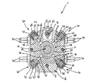
図20と21は構成要素として、流体圧容積式ポンプ4、ポンプ吐出口プラグ8、弁開放セレクタ11、開放逆止弁24、弁閉鎖セレクタ25及び閉鎖逆止弁54を一緒に、あるいはグループとして含む一つ以上の部品から成る共通ハウジングを図解する。   FIGS. 20 and 21 show as components the hydraulic positive displacement pump 4, the pump outlet plug 8, the valve opening selector 11, the opening check valve 24, the valve closing selector 25 and the closing check valve 54 together or as a group. Fig. 2 illustrates a common housing consisting of one or more parts including.

流体圧容積式ポンプ4、プラグロータ27、セレクタロータ38及び閉鎖セレクタロータ47、又はこれら4つの装置の何れかの組み合わせは、それ自身がトランスミッション装置によりエンジン12のクランク軸5により回転駆動される共通軸59により回転駆動される(図15乃至19)。   The hydraulic positive displacement pump 4, the plug rotor 27, the selector rotor 38 and the closed selector rotor 47, or any combination of these four devices are themselves driven in rotation by the crankshaft 5 of the engine 12 by the transmission device. It is rotationally driven by the shaft 59 (FIGS. 15 to 19).

共通軸59を駆動するトランスミッション装置は、溝付きベルト又はチェーン又は少なくとも一つのピニオンから成るギヤシステムによりエンジン12のクランク軸5により回転駆動されるプーリ74から成る。   The transmission device that drives the common shaft 59 comprises a pulley 74 that is rotationally driven by the crankshaft 5 of the engine 12 by a gear system comprising a grooved belt or chain or at least one pinion.

共通軸59は、プラグロータ27、開放セレクタロータ38、開放スリーブ37及び閉鎖セレクタロータ47又はこれら3つの装置の何れかの組み合わせを回転駆動し、これらの装置のいくつかの内側螺旋状溝と協同してエンジン12のクランク軸5に対するそれらの角度位相シフトを可能にする少なくとも一つの螺旋状溝60を備える。   The common shaft 59 rotationally drives the plug rotor 27, open selector rotor 38, open sleeve 37 and closed selector rotor 47 or any combination of these three devices and cooperates with some of the inner spiral grooves of these devices. And at least one helical groove 60 that allows their angular phase shift relative to the crankshaft 5 of the engine 12.

共通ハウジングはそれぞれ以下を有する、共通軸59を含みかつ端と端を揃えて組み立てられる4つの主要ハウジングから成る。即ち、
◆流体圧容積式ポンプ4とポンプ吸入口逆止弁26を備えるポンプハウジング64と、
◆プラグロータ27とポンプ吐出口29を容れたプラグハウジング65と、
◆弁リフトフォーク62、開放セレクタロータ38、弁開放分配器40、弁開放進角フォーク61、閉鎖セレクタロータ47、弁閉鎖分配器49、弁閉鎖遅角フォーク63及び開放逆止弁24を容れかつ閉鎖逆止弁54を備えることができるセレクタハウジング66と、
◆閉鎖コレクタハウジング67と
である。
The common housing consists of four main housings that include a common shaft 59 and are assembled end to end, each having the following: That is,
A pump housing 64 having a fluid pressure positive displacement pump 4 and a pump suction check valve 26;
A plug housing 65 containing the plug rotor 27 and the pump discharge port 29;
The valve lift fork 62, the open selector rotor 38, the valve open distributor 40, the valve open advance fork 61, the close selector rotor 47, the valve close distributor 49, the valve close retard fork 63 and the open check valve 24 A selector housing 66 that can include a closed check valve 54;
A closed collector housing 67.

プラグハウジング65は、それを通って流体圧容積式ポンプ4の吐出口6を、一方では、ポンプ吐出口プラグ8に接続し、他方では、プラグハウジング65とセレクタハウジング66の間の分割平面に配置されたダクト網から成る開放コレクタ68に接続するダクトを有する。   The plug housing 65 connects the outlet 6 of the hydraulic positive displacement pump 4 therethrough, on the one hand to the pump outlet plug 8, on the other hand, arranged in the dividing plane between the plug housing 65 and the selector housing 66. Having a duct connected to an open collector 68 consisting of a connected duct network.

プラグハウジング65は、それを通って流体圧容積式ポンプ4の吸入口7を、セレクタハウジング66と閉鎖コレクタ67の間の分割平面に配置されたダクト網から成る閉鎖コレクタ69に接続する導管を有する。   The plug housing 65 has a conduit through which the inlet 7 of the hydraulic positive displacement pump 4 is connected to a closed collector 69 consisting of a duct network arranged in a dividing plane between the selector housing 66 and the closed collector 67. .

セレクタハウジング66はそれを縦方向に通るダクト42を有し、これは開放コレクタ68と閉鎖コレクタ69を接続し、弁開放分配器40と弁閉鎖分配器49により遮断及び開放することができる。   The selector housing 66 has a duct 42 which runs longitudinally therethrough, which connects an open collector 68 and a closed collector 69 and can be shut off and opened by a valve open distributor 40 and a valve close distributor 49.

ダクト42は弁から外に出て行くダクト70を備え、これは弁開放分配器40と弁閉鎖分配器49の間に配置され、弁2の流体圧ジャッキ3に接続される。   The duct 42 comprises a duct 70 that exits from the valve, which is arranged between the valve opening distributor 40 and the valve closing distributor 49 and is connected to the hydraulic jack 3 of the valve 2.

セレクタハウジング66は同様にそれを縦方向に通る一つ以上のダクトを有し、これらは閉鎖コレクタ69を流体圧容積式ポンプ4の吸入口7に接続する。   The selector housing 66 also has one or more ducts that run longitudinally therethrough, which connect the closed collector 69 to the inlet 7 of the hydraulic positive displacement pump 4.

開放コレクタ68はダクトを互いに接続することを可能にし、これらのダクトはセレクタハウジング66を縦方向に通り、同じポンプ吐出口6に接続されることになっている。   The open collector 68 makes it possible to connect the ducts to each other, which ducts pass through the selector housing 66 in the longitudinal direction and are to be connected to the same pump outlet 6.

ポンプ吐出口6はプラグハウジング65を通るダクトにより開放コレクタ68に接続される。   The pump discharge port 6 is connected to the open collector 68 by a duct passing through the plug housing 65.

閉鎖コレクタ69はダクトを互いに接続することを可能にし、これらのダクトはセレクタハウジング66を縦方向に通り、同じポンプ吸入口7に接続されることになっている。   The closed collector 69 allows the ducts to be connected to each other, which ducts run vertically through the selector housing 66 and are connected to the same pump inlet 7.

ポンプ吸入口7はそれぞれセレクタハウジング66とプラグハウジング65を通るダクトにより閉鎖コレクタ69に接続される。   The pump suction port 7 is connected to the closed collector 69 by a duct passing through the selector housing 66 and the plug housing 65, respectively.

組み立てネジ71が、種々のハウジング64、65、66及び67を組み立てられた状態に維持するためにそれらを真っ直ぐに通っており、一つ以上の前記組み立てネジ71は、弁2の開放、リフト及び閉鎖を制御可能にするフォーク61、62及び63のための摺動路として役立つ。   Assembly screws 71 pass straight through the various housings 64, 65, 66 and 67 to keep them assembled, and one or more of the assembly screws 71 can be used to open the valve 2, lift and Serves as a sliding path for the forks 61, 62 and 63 to allow the closure to be controlled.

弁開放進角フォーク61、弁リフトフォーク62及び弁閉鎖遅角フォーク63はコンピュータにより制御されかつトランスミッション手段により前記フォーク61、62及び63に接続された電動機により並進に関して作動される。   The valve opening advance fork 61, the valve lift fork 62 and the valve closing retard fork 63 are controlled by a computer and actuated in translation by a motor connected to the forks 61, 62 and 63 by transmission means.

ポンプ吐出口29において、プラグロータ27の突起28が、特に共通軸59を備える共通ハウジングの内側への噴出を遮断し、前記共通ハウジングは、
◆ダクトによりエンジン潤滑オイルハウジング72に、
◆又はエンジン12の加圧された潤滑回路15に、
◆又はエンジン潤滑オイルハウジング72とは独立な流体圧流体ハウジング
に接続され、
◆あるいは更なるポンプ13により圧力の下に維持される
閉じられたチャンバを形成する。
In the pump discharge port 29, the protrusion 28 of the plug rotor 27 blocks the jetting of the common housing provided with the common shaft 59 in particular,
◆ The engine lubrication oil housing 72 is connected by a duct.
◆ or in the pressurized lubrication circuit 15 of the engine 12
◆ or connected to a hydraulic fluid housing independent of the engine lubricating oil housing 72;
◆ or form a closed chamber that is maintained under pressure by a further pump 13.

特定の実施例において、高圧流体圧回路10に接続された同じダクトが流量分割器を介して複数の流体圧ジャッキ3に同時に供給することができ、これにより前記流体圧ジャッキ3により作動される弁2が確実に実質的に同一のリフトを持つことが可能であることが特筆される。   In a particular embodiment, the same duct connected to the high-pressure fluid pressure circuit 10 can be fed simultaneously to a plurality of fluid pressure jacks 3 via a flow divider, whereby the valve operated by said fluid pressure jack 3 It is noted that the two can certainly have substantially the same lift.

本発明による装置の機能は以上の説明から理解される。   The function of the device according to the invention can be understood from the above description.

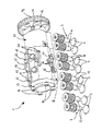
図1は(例えば4気筒エンジンの4つの吸気又は排気弁を作動するための)4つの弁を有する構造の装置の基本図を図解する。   FIG. 1 illustrates a basic view of an apparatus having a structure having four valves (eg, for operating four intake or exhaust valves of a four cylinder engine).

そこでは、一つ又はその他の流体圧ジャッキ3により開かれるべき弁がないときは、流体圧容積式ポンプ4は低圧回路9からポンプ吸入口逆止弁26を介してこのエンジン潤滑回路に来る流体圧流体を、そのとき開いているポンプ吐出口プラグ8を介してエンジン潤滑剤ハウジング58に向けて吐出することが分る。   There, when there is no valve to be opened by one or the other hydraulic jack 3, the fluid positive displacement pump 4 flows from the low pressure circuit 9 to this engine lubrication circuit via the pump inlet check valve 26. It can be seen that the pressurized fluid is discharged toward the engine lubricant housing 58 via the pump outlet plug 8 which is then open.

弁を開くべきときは、弁開放セレクタ11は前記弁の流体圧ジャッキ3を、流体圧容積式ポンプ4の吐出口から来る高圧回路10と関連付ける。   When the valve is to be opened, the valve opening selector 11 associates the valve's fluid pressure jack 3 with the high pressure circuit 10 coming from the outlet of the fluid displacement pump 4.

次いで、ポンプ吐出口プラグ8がポンプ吐出口ダクト32を閉じ、それにより高圧回路10内の圧力を上げて流体圧ジャッキ3が選択された弁を開く。   The pump outlet plug 8 then closes the pump outlet duct 32, thereby increasing the pressure in the high pressure circuit 10 and opening the selected valve by the fluid pressure jack 3.

弁が十分にリフトされるときは、ポンプ吐出口プラグ8はポンプ吐出口ダクト32を再び開き、それにより、弁のリフトを停止する。それは開放逆止弁24の上流の高圧回路10の圧力が弁の戻りバネの作用により流体圧ジャッキ3のチャンバ内に広がる圧力より低くなるからである。   When the valve is fully lifted, the pump outlet plug 8 reopens the pump outlet duct 32, thereby stopping the valve lift. This is because the pressure of the high-pressure circuit 10 upstream of the open check valve 24 becomes lower than the pressure spreading in the chamber of the fluid pressure jack 3 by the action of the return spring of the valve.

前記弁は開放逆止弁24の作用により開いたままである。   The valve remains open by the action of the open check valve 24.

弁の閉鎖は、選択された瞬間に前記弁の流体圧ジャッキ3を、高圧回路10を介して流体圧容積式ポンプ4の吸入口と関連付ける弁閉鎖セレクタ25により制御される。   The closing of the valve is controlled by a valve closing selector 25 which associates the valve's hydraulic jack 3 with the inlet of the hydraulic positive displacement pump 4 via the high pressure circuit 10 at the selected moment.

前記高圧回路10の圧力の急な上昇の結果、ポンプ吸入口逆止弁26の作用によりエンジン潤滑回路から来る流体圧流体の到着を閉鎖し、流体圧流体を前記流体圧容積式ポンプ4の吸入口に押しやり、それにより弁バネの圧縮の結果として吸収された機械的仕事の大部分を回収し、また前記弁の閉鎖速度を制御することを可能にする。   As a result of the sudden increase in the pressure of the high-pressure circuit 10, the action of the pump inlet check valve 26 closes the arrival of fluid pressure fluid coming from the engine lubrication circuit, and the fluid pressure fluid is sucked into the fluid pressure positive displacement pump 4. It pushes to the mouth, thereby recovering most of the mechanical work absorbed as a result of compression of the valve spring and also makes it possible to control the closing speed of the valve.

弁がその弁座に休止しているときは、流体圧容積式ポンプ4は低圧回路9から来る流体圧流体を、ポンプ吸入口逆止弁26を介してエンジン潤滑ハウジング58に向けて再び吐出する。   When the valve is resting on its valve seat, the hydraulic positive displacement pump 4 again discharges the hydraulic fluid coming from the low pressure circuit 9 toward the engine lubrication housing 58 via the pump inlet check valve 26. .

二つの異なる弁の同時開閉が可能であり、その場合、流体圧容積式ポンプ4の吸入口が閉鎖作動を受けた一つの弁の流体圧ジャッキ3により供給され、一方、前記流体圧容積式ポンプ4から出る流体圧流体がポンプ吐出プラグ8により開放作動を受けたもう一つの弁の流体圧ジャッキ3に強制的に供給されることは特筆されてもよい。   It is possible to open and close two different valves simultaneously, in which case the inlet of the hydraulic positive displacement pump 4 is supplied by a hydraulic jack 3 of one valve which has undergone a closing operation, while the hydraulic positive displacement pump It may be noted that the fluid pressure fluid coming out of 4 is forcibly supplied to the fluid pressure jack 3 of another valve that has been opened by the pump discharge plug 8.

図2はその機能が前のものと同一であるが、シリンダにつき二つの吸気又は排気弁を有する4気筒エンジンの8つの吸気又は排気弁を作動するように意図された回路の模式図である。   FIG. 2 is a schematic diagram of a circuit that is identical in function to the previous one, but intended to operate eight intake or exhaust valves of a four cylinder engine having two intake or exhaust valves per cylinder.

この構造によれば、図8に図解されるように、一つのロータを有しかつ内側のカムが定める二つの隔離された吸入口と二つの隔離された吐出口が設けられたベーンポンプを用いることができる。   According to this structure, as illustrated in FIG. 8, a vane pump having one rotor and having two isolated suction ports and two isolated discharge ports defined by an inner cam is used. Can do.

ポンプ吐出口プラグ8、弁開放セレクタ11及び弁閉鎖セレクタ25は電磁弁により実施してもよいが、熱的エンジンの環境における壊れ易さ、丈夫さの欠如、前記電磁弁の動作均一性の欠如はそのような実施を難しくしている。   The pump outlet plug 8, the valve opening selector 11 and the valve closing selector 25 may be implemented by solenoid valves, but they are fragile in the thermal engine environment, lack of robustness, and lack of uniformity of operation of the solenoid valves. Makes such an implementation difficult.

このために、前記電磁弁は、自動車エンジンにおいて探求される動作の信頼性と一定性を与える図15乃至21に示す機械的装置により置き換えられるのが好都合である。これらの図に図解された装置は特にシリンダに付き二つの吸気弁又は二つの排気弁を有する4気筒エンジンの8つの吸気又は排気弁を作動するように意図される。   For this purpose, the solenoid valve is advantageously replaced by a mechanical device as shown in FIGS. 15 to 21 which gives the reliability and consistency of the operation sought in an automobile engine. The devices illustrated in these figures are specifically intended to operate eight intake or exhaust valves of a four cylinder engine having two intake valves or two exhaust valves per cylinder.

他のエンジン構造に対するそのような装置の変形は当業者には直ちに明らかとなろう。   Variations of such devices for other engine structures will be readily apparent to those skilled in the art.

共通軸59は、エンジン12により、従来のカム軸と同じ速度、即ちエンジン12のクランク軸5の半分の速度で回転するプーリ74により、装置をプーリ74側から見て時計方向に回転駆動される。   The common shaft 59 is rotationally driven by the engine 12 in the clockwise direction when the device is viewed from the pulley 74 side by a pulley 74 that rotates at the same speed as the conventional cam shaft, that is, half the speed of the crankshaft 5 of the engine 12. .

こうして、特定の実施例によれば、装置は全体として、それが置き換わるカム軸(例えば、吸気カム軸)に代わって所定の場所に置かれ、図9に示すように、もう一つのカム軸(例えば、排気カム軸)を有するエンジンの分配ベルトにより駆動され、あるいは図10に示すように、もう一つの同一の装置を有する前記ベルトにより駆動される。   Thus, according to a particular embodiment, the device as a whole is put in place in place of the camshaft it replaces (for example, the intake camshaft) and, as shown in FIG. For example, it is driven by a distribution belt of an engine having an exhaust camshaft) or by the belt having another identical device as shown in FIG.

流体圧容積式ポンプ4は、互いに連通しない二つのポンプ吸入口7と二つのポンプ吐出口6を定める内側カムを有するベーンタイプであり、ポンプ吸入口逆止弁26は低圧回路9、この特定の場合はエンジン12の加圧された潤滑回路に接続され、バネによりそれらの弁座に押し付け接触状態に保たれるボールから成る。   The fluid pressure positive displacement pump 4 is a vane type having an inner cam that defines two pump suction ports 7 and two pump discharge ports 6 that do not communicate with each other, and the pump suction check valve 26 is a low-pressure circuit 9, It consists of a ball which is connected to the pressurized lubrication circuit of the engine 12 and is kept in contact with the valve seats by means of a spring.

開放すべき弁がないときは、流体圧容積式ポンプ4は流体圧流体をポンプ吐出口ダクト32を介してプラグハウジング65の内側空洞に排出し、前記空洞は図解されないダクトによりエンジン潤滑オイルハウジング72に接続される。   When there is no valve to open, the hydraulic positive displacement pump 4 discharges the hydraulic fluid into the inner cavity of the plug housing 65 via the pump outlet duct 32, which is not illustrated by the engine lubricating oil housing 72. Connected to.

図で分るように、共通軸59は螺旋状溝60を備え、これらの溝はプラグロータ27、開放セレクタロータ38及び閉鎖セレクタロータ47を回転駆動する。   As can be seen, the common shaft 59 is provided with helical grooves 60 which drive the plug rotor 27, open selector rotor 38 and closed selector rotor 47 in rotation.

ここではプラグロータ27と開放セレクタロータ38は、それらが回転に関して同じスリーブ37と一体的であるので互いに同位相のままであり、これにより、弁2の選択とポンプ吐出口6の遮断の開始の間の一定時間を保証する。   Here, the plug rotor 27 and the open selector rotor 38 remain in phase with each other since they are integral with the same sleeve 37 with respect to rotation, thereby enabling the selection of the valve 2 and the start of the shutoff of the pump outlet 6. Guarantee a certain time between.

ポンププラグ8、弁開放セレクタ11及び弁閉鎖セレクタ25の機能は、それらが全て共通軸59により駆動されるので必ず同期することは特筆されるかも知れない。   It may be noted that the functions of the pump plug 8, valve open selector 11 and valve close selector 25 are always synchronized because they are all driven by a common shaft 59.

ハウジング内で互いに直径方向に対向して配置されたここでは二つのポンプ吐出口プラグ8はそれぞれ流体圧容積式ポンプ4の二つのポンプ吐出口6の一方を遮断し、それぞれのポンプ吐出口8はエンジン12のシリンダの偶数弁2か、奇数弁2のどちらかの開放のみを任される。   Here, two pump outlet plugs 8, which are arranged diametrically opposite each other in the housing, respectively block one of the two pump outlets 6 of the hydraulic positive displacement pump 4, and each pump outlet 8 is Only the opening of either the even valve 2 or the odd valve 2 of the cylinder of the engine 12 is entrusted.

同じ瞬間に同じ運動を有する同じシリンダの偶数及び奇数弁2は従ってそれらの機能の点で連結される   Even and odd valves 2 of the same cylinder having the same movement at the same moment are therefore connected in terms of their function

同様に、二つのポンプ吸入口7はエンジン12のシリンダの偶数弁2か奇数弁2のどちらかの閉鎖のみを任される。   Similarly, the two pump inlets 7 are only responsible for closing either the even valve 2 or the odd valve 2 of the cylinder of the engine 12.

プラグロータ27は90度ごとに配置された4つの可変外形の突起28を備える。   The plug rotor 27 includes four variable-shaped protrusions 28 arranged every 90 degrees.

ポンプ吐出口29はプラグハウジング65内に固定して取り付けられるので、開放スリーブ37上のプラグロータ27の並進はポンプ吐出口29に面する突起28の作動長を変化し、それにより、弁2の開放が行われるクランク軸5の度数を増減することを可能にする。   Since the pump outlet 29 is fixedly mounted in the plug housing 65, translation of the plug rotor 27 on the open sleeve 37 changes the operating length of the projection 28 facing the pump outlet 29, thereby It is possible to increase or decrease the frequency of the crankshaft 5 to be opened.

弁2がエンジン12の所定の動作条件の下に一定速度で開くので、開放に関してそれらが長く作動されればされるほど、それらのリフト高さは大きくなる。   Since the valves 2 open at a constant speed under predetermined operating conditions of the engine 12, the longer they are actuated for opening, the greater their lift height.

その結果、弁リフトフォーク62は弁2のリフト高さを制御することを可能にし、前記フォークは図解されないコンピュータにより制御される、図解されない電動機により作動される。   As a result, the valve lift fork 62 makes it possible to control the lift height of the valve 2, said fork being actuated by an unillustrated electric motor controlled by an unillustrated computer.

弁2の開放に対する出発点は弁開放進角フォーク61により共通軸59に対して縦方向の並進として変位される開放スリーブ37により弁2のリフトとは独立に制御することができる。   The starting point for the opening of the valve 2 can be controlled independently of the lift of the valve 2 by an opening sleeve 37 which is displaced by a valve opening advance fork 61 as a longitudinal translation with respect to the common shaft 59.

この作用はエンジン12のクランク軸5に対して角度的にプラグロータ27の位相をシフトすることを可能にし、開放スリーブ37の内側螺旋状溝75は共通軸59の外側螺旋状溝60と協同し、この結果、プラグロータ27の突起28が、弁リフトフォーク62の制御の下にあるそれらの作動長を変化することなく、いつかはポンプ吐出口29を遮断する。   This action makes it possible to shift the phase of the plug rotor 27 angularly with respect to the crankshaft 5 of the engine 12, and the inner spiral groove 75 of the open sleeve 37 cooperates with the outer spiral groove 60 of the common shaft 59. As a result, the protrusions 28 of the plug rotor 27 sometime block the pump outlet 29 without changing their operating length under the control of the valve lift fork 62.

弁開放進角フォーク61は図解されないコンピュータにより制御される、図解されない電動機により作動される。   The valve opening advance fork 61 is operated by an unillustrated electric motor controlled by an unillustrated computer.

弁開放セレクタ11と弁閉鎖セレクタ25は共に同じ動作原理に基づいている。   Both the valve opening selector 11 and the valve closing selector 25 are based on the same operating principle.

開放セレクタのカム39が、4行程オット−ボ・ドゥ・ローシャ・サイクル(Otto or Beau de Rochas cycle)による4気筒エンジン動作の要件により、共通軸59の90度回転ごとの、即ち、クランク軸5の180度回転ごとの開放に関して弁開放分配器40を作動することが特筆されるであろう。   Depending on the requirements of the four-cylinder engine operation with a four-stroke Otto or Beau de Rochas cycle, the open selector cam 39 is driven every 90 degrees of the common shaft 59, ie the crankshaft 5 It will be noted that the valve opening distributor 40 is actuated for opening every 180 degrees of rotation.

それぞれの弁開放分配器40は流体圧流体を同じシリンダの偶数弁2と奇数弁2の流体圧ジャッキ3に供給するダクト42を同時に開閉することを可能にする。   Each valve opening distributor 40 makes it possible to simultaneously open and close ducts 42 which supply hydraulic fluid to the hydraulic jacks 3 of the even and odd valves 2 and 2 of the same cylinder.

この結果は、弁開放分配器40の円筒片78に配置され、カム39が弁開放分配器40を作動できるときはどちらかが前記ダクト42の反対にあり、カム39がそれらを作動しないときは前記ダクト42を遮断する溝41により得られる。   This result is located on the cylindrical piece 78 of the valve opening distributor 40 and when the cam 39 can actuate the valve opening distributor 40, either is opposite the duct 42 and when the cam 39 does not actuate them. It is obtained by a groove 41 that blocks the duct 42.

円筒片78は、バネ43によりセレクタハウジング66との接触が保たれた前記円筒片のショルダ44によりカム39に対して所望の距離まで戻される。   The cylindrical piece 78 is returned to a desired distance from the cam 39 by the shoulder 44 of the cylindrical piece, which is kept in contact with the selector housing 66 by the spring 43.

弁2の閉鎖に対する出発点は弁閉鎖遅角フォーク63により共通軸59に対して縦方向の並進として変位される閉鎖セレクタロータ47により制御される。   The starting point for the closing of the valve 2 is controlled by a closing selector rotor 47 which is displaced as a longitudinal translation with respect to the common shaft 59 by a valve closing retard fork 63.

この作用はエンジン12のクランク軸5に対して角度的に閉鎖セレクタロータ47の位相をシフトすることを可能にし、前記閉鎖セレクタロータ47の内側螺旋状溝79は共通軸59の外側螺旋状溝60と協同し、この結果、遅かれ早かれ弁2を閉じるために弁閉鎖分配器49が遅かれ早かれ作動される。   This action makes it possible to shift the phase of the closed selector rotor 47 angularly with respect to the crankshaft 5 of the engine 12, and the inner helical groove 79 of the closed selector rotor 47 is the outer helical groove 60 of the common shaft 59. As a result, the valve closing distributor 49 is activated sooner or later to close the valve 2 sooner or later.

共通ハウジングが、中に少なくとも一つの流体圧ジャッキ3が収容される台座を備えてもよく、前記台座はエンジン12のシリンダヘッドに固定され、それにより、各流体圧ジャッキ3が前記エンジン12の対応する弁2の軸の上端に接触し、前記弁を作動できることが特筆される。   The common housing may comprise a pedestal in which at least one fluid pressure jack 3 is accommodated, said pedestal being fixed to the cylinder head of the engine 12 so that each fluid pressure jack 3 corresponds to the engine 12. It is noted that the valve can be actuated by contacting the upper end of the shaft of the valve 2 to be operated.

以上の説明は例としてのみ行われ、発明の範囲を決して限定せず、述べられた実施の詳細が他の如何なる均等物により置き換えられたとしてもその発明の範囲から逸脱しないことは言うまでもない。   The foregoing description is given by way of example only and in no way limits the scope of the invention, and it goes without saying that the details of the implementation described may be replaced by any other equivalents without departing from the scope of the invention.

(例えば4気筒エンジンの4つの吸気弁を作動するための)4つの弁を有する構造の本発明による流体圧アクチュエータの基本図を図解する。Fig. 2 illustrates a basic view of a fluid pressure actuator according to the invention of a structure having four valves (for example for operating four intake valves of a four cylinder engine). その機能が前のものと同一であるが、例えばシリンダにつき二つの吸気弁を有する4気筒エンジンの8つの吸気弁を作動するように意図された回路の模式図である。FIG. 2 is a schematic diagram of a circuit whose function is identical to that of the previous one, but intended to operate, for example, eight intake valves of a four-cylinder engine having two intake valves per cylinder. その機能が前のものと同一であるが、更なるポンプにより、より高い圧力で動作する回路の模式図であり、これが本発明による装置の動作精度に関して流体圧流体の圧縮性と、弁の慣性の結果を制限することになる。Fig. 2 is a schematic diagram of a circuit whose function is the same as the previous one, but which is operated at higher pressures by means of a further pump, which is the compressibility of the hydraulic fluid and the inertia of the valve with respect to the operating accuracy of the device according to the invention. Will limit the results. 本発明による流体圧アクチュエータを示す斜視図である。It is a perspective view which shows the fluid pressure actuator by this invention. 本発明による流体圧アクチュエータにより制御されるエンジンの弁を詳細に図解する図である。FIG. 2 illustrates in detail an engine valve controlled by a fluid pressure actuator according to the present invention. 本発明による流体圧アクチュエータにより制御されるエンジンの弁を詳細に図解する図である。FIG. 2 illustrates in detail an engine valve controlled by a fluid pressure actuator according to the present invention. 本発明による流体圧アクチュエータにより制御されるエンジンの弁を詳細に図解する図である。FIG. 2 illustrates in detail an engine valve controlled by a fluid pressure actuator according to the present invention. 本発明による流体圧アクチュエータの流体圧ポンプの吸入口と吐出口を示す断面図である。It is sectional drawing which shows the suction inlet and discharge outlet of the fluid pressure pump of the fluid pressure actuator by this invention. 本発明による流体圧アクチュエータのエンジンへの可能な配置を図解する断面図である。1 is a cross-sectional view illustrating a possible arrangement of a fluid pressure actuator according to the present invention in an engine. 本発明による流体圧アクチュエータのエンジンへの可能な配置を図解する断面図である。1 is a cross-sectional view illustrating a possible arrangement of a fluid pressure actuator according to the present invention in an engine. 本発明による流体圧アクチュエータのポンプ吐出口プラグを図解する図である。FIG. 3 illustrates a pump outlet plug of a fluid pressure actuator according to the present invention. 本発明による流体圧アクチュエータのポンプ吐出口プラグを図解する図である。FIG. 3 illustrates a pump outlet plug of a fluid pressure actuator according to the present invention. 本発明による流体圧アクチュエータのポンプ吐出口プラグを図解する図である。FIG. 3 illustrates a pump outlet plug of a fluid pressure actuator according to the present invention. 本発明による流体圧アクチュエータの弁開放セレクタを示す断面図である。It is sectional drawing which shows the valve opening selector of the fluid pressure actuator by this invention. 本発明による流体圧アクチュエータの種々の構成要素の組み立てを図解する図である。FIG. 3 illustrates the assembly of various components of a fluid pressure actuator according to the present invention. 本発明による流体圧アクチュエータの種々の構成要素の組み立てを図解する図である。FIG. 3 illustrates the assembly of various components of a fluid pressure actuator according to the present invention. 本発明による流体圧アクチュエータの種々の構成要素の組み立てを図解する図である。FIG. 3 illustrates the assembly of various components of a fluid pressure actuator according to the present invention. 本発明による流体圧アクチュエータの種々の構成要素の組み立てを図解する図である。FIG. 3 illustrates the assembly of various components of a fluid pressure actuator according to the present invention. 本発明による流体圧アクチュエータの種々の構成要素の組み立てを図解する図である。FIG. 3 illustrates the assembly of various components of a fluid pressure actuator according to the present invention. 本発明による流体圧アクチュエータの種々の構成要素の組み立てを図解する図である。FIG. 3 illustrates the assembly of various components of a fluid pressure actuator according to the present invention. 本発明による流体圧アクチュエータの種々の構成要素の組み立てを図解する図である。FIG. 3 illustrates the assembly of various components of a fluid pressure actuator according to the present invention. その機能が図1乃至3に示す前のものと同一であるが、そのポンプ吐出口プラグと弁開放セレクタが一つの組み合わされた分配器に寄せ集められた回路の模式図である。FIG. 4 is a schematic diagram of a circuit whose function is the same as the previous one shown in FIGS. 1 to 3, but whose pump outlet plug and valve open selector are brought together in one combined distributor.

符号の説明Explanation of symbols

1 流体圧アクチュエータ
2 弁
3 流体圧ジャッキ
4 流体圧容積式ポンプ
5 クランク軸
6 吐出口
7 吸入口
8 ポンプ吐出口プラグ
9 低圧流体圧回路
10 高圧流体圧回路
11 弁開放セレクタ
12 エンジン
13 更なるポンプ
14 蓄圧器
15 加圧された潤滑回路
16 弁ガイド
17 シール
18 弁軸
19 ショルダ
20 チャンバ
21 排気ダクト
22 ドレーン
23 小さいショルダ
24 弁開放逆止弁
25 弁閉鎖セレクタ
26 ポンプ吸入口逆止弁
27 プラグロータ
28 突起
29 ポンプ吐出口
30 ポンプ吐出口と突起との接触を維持する装置
31 プラグピストン
32ポンプ吐出口ダクト
33 ラジアルポート
34 真っ直ぐな内側溝
37 開放スリーブ
38 開放セレクタロータ
39 カム
40 弁開放分配器
41 溝
42 ダクト
43 バネ
44 ショルダ
45 キャップ
46 チャンバ
47 閉鎖セレクタロータ
48 カム
49 弁閉鎖分配器
50 溝
51 ショルダ
52 バネ
53 キャップ
54 閉鎖逆止弁
56 バネ
58 タンク
59 共通軸
60 外側螺旋状溝
61 弁開放進角フォーク
62 弁リフトフォーク
63 弁閉鎖遅角フォーク
64 ポンプハウジング
65 プラグハウジング
66 セレクタハウジング
67 閉鎖コレクタハウジング
68 開放コレクタ
69 閉鎖コレクタ
70 弁から外に出て行くダクト
71 組み立てネジ
72 エンジン潤滑オイルハウジング
73 チャンバ
74 プーリ
75 内側螺旋状溝
76 真っ直ぐな外側溝
77 螺旋状溝
78 円筒片
79 螺旋状溝
80 円筒片
DESCRIPTION OF SYMBOLS 1 Fluid pressure actuator 2 Valve 3 Fluid pressure jack 4 Fluid pressure positive displacement pump 5 Crankshaft 6 Discharge port 7 Suction port 8 Pump discharge port plug 9 Low pressure fluid pressure circuit 10 High pressure fluid pressure circuit 11 Valve open selector 12 Engine 13 Further pump 14 Accumulator 15 Pressurized Lubrication Circuit 16 Valve Guide 17 Seal 18 Valve Shaft 19 Shoulder 20 Chamber 21 Exhaust Duct 22 Drain 23 Small Shoulder 24 Valve Opening Check Valve 25 Valve Closed Selector 26 Pump Inlet Check Valve 27 Plug Rotor 28 Projection 29 Pump Discharge Port 30 Device for Maintaining Contact between Pump Discharge Port and Protrusion 31 Plug Piston 32 Pump Discharge Port Duct 33 Radial Port 34 Straight Inner Groove 37 Open Sleeve 38 Open Selector Rotor 39 Cam 40 Valve Open Distributor 41 Groove 42 Duc 43 spring 44 shoulder 45 cap 46 chamber 47 closing selector rotor 48 cam 49 valve closing distributor 50 groove 51 shoulder 52 spring 53 cap 54 closing check valve 56 spring 58 tank 59 common shaft 60 outer spiral groove 61 valve opening advance fork 62 Valve lift fork 63 Valve closing retard fork 64 Pump housing 65 Plug housing 66 Selector housing 67 Closed collector housing 68 Open collector 69 Closed collector 70 Duct exiting from valve 71 Assembly screw 72 Engine lubrication oil housing 73 Chamber 74 Pulley 75 Inner spiral groove 76 Straight outer groove 77 Spiral groove 78 Cylindrical piece 79 Spiral groove 80 Cylindrical piece

Claims (57)

ダクトにより高圧流体圧回路(10)に接続され、少なくとも一つの弁(2)を確実に開放させる少なくとも一つの流体圧ジャッキ(3)と、
少なくとも一つの吐出口と、少なくとも一つの吸入口とを備え、エンジンのクランク軸の速度に比例する速度で回転する少なくとも一つの流体圧容積式ポンプ(4)と、
前記流体圧容積式ポンプ(4)の前記吐出口に吐出された流体圧流体が低圧回路(9)又はタンク(58)に噴出しないようにし、また一つ以上の弁(2)を確実に開放させる一つ以上の流体圧ジャッキ(3)と連通する高圧回路(10)に入ることを可能にする少なくとも一つのポンプ吐出口プラグ(8)と、
前記高圧回路(10)を介して、前記流体圧容積式ポンプ(4)の前記吐出口において吐出された流体圧流体を少なくとも一つの弁(2)の前記流体圧ジャッキ(3)に向けてその弁を開くことを可能にし、一方、それと同時に前記流体圧流体が一つ以上の他の弁(2)に向けられないようにしてその弁を閉じたままにする少なくとも一つの弁開放セレクタ(11)と、
前記流体圧容積式ポンプ(4)の吐出口と少なくとも一つの弁(2)の前記流体圧ジャッキ(3)の間の前記高圧回路(10)に配置され、弁を開放し続けるために前記弁(2)の前記流体圧ジャッキ(3)内に流体圧流体を保持することを可能にする少なくとも一つの開放逆止弁(24)と、
前記開放逆止弁(24)により開放され続ける少なくとも一つの弁(2)の前記流体圧ジャッキ(3)に容れられた流体圧流体を前記流体圧容積式ポンプ(4)の吸入口に向け、それにより、前記弁(2)を確実に閉鎖させ、かつそれらの流体圧ジャッキ(3)に容れられた流体圧流体が他の弁(2)の流体圧ジャッキ(3)に導入されないようにしてその弁を閉じた位置に維持することを可能にする少なくとも一つの弁閉鎖セレクタ(25)と、
前記流体圧容積式ポンプ(4)の前記吸入口に位置し、前記低圧回路(9)又は前記タンク(58)の圧力が前記流体圧容積式ポンプ(4)の前記吸入口の圧力より高いときに前記低圧回路(9)又は前記タンク(58)の流体圧流体が前記流体圧容積式ポンプ(4)の吸入口に入ることを可能にする少なくとも一つのポンプ吸入口逆止弁(26)と
を備えることを特徴とするレシプロエンジン用流体圧弁アクチュエータ。
At least one fluid pressure jack (3) connected to the high pressure fluid pressure circuit (10) by a duct and reliably opening at least one valve (2);
At least one fluid pressure positive displacement pump (4) comprising at least one outlet and at least one inlet and rotating at a speed proportional to the speed of the crankshaft of the engine;
The fluid pressure fluid discharged to the discharge port of the fluid pressure positive displacement pump (4) is prevented from being ejected to the low pressure circuit (9) or the tank (58), and one or more valves (2) are reliably opened. At least one pump outlet plug (8) allowing entry into a high pressure circuit (10) in communication with one or more fluid pressure jacks (3)
The fluid pressure fluid discharged from the discharge port of the fluid pressure positive displacement pump (4) through the high pressure circuit (10) is directed to the fluid pressure jack (3) of at least one valve (2). At least one valve opening selector (11) that allows the valve to open, while at the same time preventing the hydraulic fluid from being directed to one or more other valves (2) )When,
Arranged in the high pressure circuit (10) between the outlet of the fluid pressure positive displacement pump (4) and the fluid pressure jack (3) of at least one valve (2) to keep the valve open At least one open check valve (24) enabling fluid pressure fluid to be retained in the fluid pressure jack (3) of (2);
Directing the fluid pressure fluid contained in the fluid pressure jack (3) of at least one valve (2) that is kept open by the opening check valve (24) to the inlet of the fluid pressure positive displacement pump (4); Thereby, the valve (2) is securely closed, and the fluid pressure fluid contained in the fluid pressure jack (3) is not introduced into the fluid pressure jack (3) of the other valve (2). At least one valve closure selector (25) that allows the valve to be maintained in a closed position;
When the pressure of the low pressure circuit (9) or the tank (58) is higher than the pressure of the suction port of the fluid pressure positive displacement pump (4), located at the suction port of the fluid pressure positive displacement pump (4) At least one pump inlet check valve (26) that allows hydraulic fluid in the low pressure circuit (9) or tank (58) to enter the inlet of the fluid positive displacement pump (4); A fluid pressure valve actuator for a reciprocating engine.
シリンダと、弁(2)を確実に開放させる前記流体圧ジャッキ(3)のチャンバ(20)が弁ガイド(16)に配置され、前記シリンダと前記チャンバ(20)が、弁(2)を開くために弁軸(18)に配置されたショルダ(19)から成るジャッキピストンと協同することを特徴とする請求項1に記載のレシプロエンジン用流体圧弁アクチュエータ。  A cylinder and a chamber (20) of the fluid pressure jack (3) that reliably opens the valve (2) are arranged in a valve guide (16), and the cylinder and the chamber (20) open the valve (2). 2. A hydraulic valve actuator for a reciprocating engine according to claim 1, characterized in that it cooperates with a jack piston consisting of a shoulder (19) arranged on the valve stem (18). 前記弁軸(18)に配置されたショルダ(19)から成る前記ジャッキピストンが前記弁ガイド(16)内での弁(2)のガイドに関与することを特徴とする請求項2に記載のレシプロエンジン用流体圧弁アクチュエータ。  Reciprocating device according to claim 2, characterized in that the jack piston consisting of a shoulder (19) arranged on the valve stem (18) is involved in the guide of the valve (2) in the valve guide (16). Fluid pressure valve actuator for engine. 前記弁軸(18)上のショルダ(19)から成る前記ジャッキピストンが少なくとも一つのシール(17)を備えることを特徴とする請求項2に記載のレシプロエンジン用流体圧弁アクチュエータ。  3. A hydraulic valve actuator for a reciprocating engine according to claim 2, characterized in that the jack piston consisting of a shoulder (19) on the valve stem (18) comprises at least one seal (17). 前記弁ガイド(16)が吸気又は排気ダクト(21)の近傍に、前記吸気又は排気ダクト(21)に向う流体圧流体の通路を制限するためにエンジン(12)のシリンダヘッドに設けられた少なくとも一つのドレーン(22)を備えることを特徴とする請求項2に記載のレシプロエンジン用流体圧弁アクチュエータ。  At least the valve guide (16) is provided in the cylinder head of the engine (12) in the vicinity of the intake or exhaust duct (21) to restrict the passage of fluid pressure fluid toward the intake or exhaust duct (21). The hydraulic valve actuator for a reciprocating engine according to claim 2, characterized in that it comprises one drain (22). 弁(2)を確実に開放させる前記流体圧ジャッキ(3)が、弁(2)がそれらの弁座と接触する前に前記弁を制動することを可能にする限界−停止減衰装置を備えることを特徴とする請求項1に記載のレシプロエンジン用流体圧弁アクチュエータ。  The hydraulic jack (3) that reliably opens the valve (2) comprises a limit-stop damping device that allows the valve (2) to brake the valve before it contacts the valve seat. The fluid pressure valve actuator for a reciprocating engine according to claim 1. 前記弁ガイド(16)に配置された前記流体圧ジャッキ(3)が前記弁軸(18)に配置された小さいショルダ(23)であって、小さい高さと、前記小さいショルダ(23)より実質的に大きい直径とを有するシリンダ部と協同する小さいショルダから成る限界−停止減衰装置を備え、前記シリンダ部が前記弁ガイド(16)の上部に配置され、それにより、弁(2)が閉鎖行程の終りに到達するときに流体圧流体を剪断し、その効果が前記弁(2)の速度を減ずることであることを特徴とする請求項6に記載のレシプロエンジン用流体圧弁アクチュエータ。  The fluid pressure jack (3) disposed on the valve guide (16) is a small shoulder (23) disposed on the valve shaft (18), which is substantially smaller than a small height and the small shoulder (23). A limit-stop dampening device consisting of a small shoulder cooperating with a cylinder portion having a large diameter at the top of the valve guide (16), so that the valve (2) is in the closing stroke. 7. The hydraulic valve actuator for a reciprocating engine according to claim 6, wherein the hydraulic fluid is sheared when reaching the end, the effect being to reduce the speed of the valve (2). 少なくとも一つの弁(2)を確実に開放させる前記流体圧ジャッキ(3)がそのチャンバ(20)の領域に抜き取り装置を備え、前記抜き取り装置が、前記チャンバ(20)内に容れられた流体圧流体が低圧回路に逃げられるようにするために命令手段により開放できるプラグから成ることを特徴とする請求項1に記載のレシプロエンジン用流体圧弁アクチュエータ。  The fluid pressure jack (3) for reliably opening at least one valve (2) comprises an extraction device in the region of the chamber (20), the extraction device being a fluid pressure contained in the chamber (20). 2. A hydraulic valve actuator for a reciprocating engine according to claim 1, comprising a plug that can be opened by command means to allow fluid to escape to the low pressure circuit. 少なくとも一つの弁(2)がある瞬間における弁のリフト高さについてコンピュータに知らせる電気又は電磁信号を発する測定装置を備えることを特徴とする請求項1に記載のレシプロエンジン用流体圧弁アクチュエータ。  2. A hydraulic valve actuator for a reciprocating engine according to claim 1, characterized in that it comprises a measuring device for producing an electrical or electromagnetic signal that informs the computer about the lift height of the valve at a certain moment. 前記低圧回路(9)がエンジン(12)の加圧された潤滑回路(15)に接続されることを特徴とする請求項1に記載のレシプロエンジン用流体圧弁アクチュエータ。  2. A hydraulic valve actuator for a reciprocating engine according to claim 1, wherein the low pressure circuit (9) is connected to a pressurized lubrication circuit (15) of the engine (12). 前記低圧回路(9)がエンジン(12)の加圧された潤滑回路(15)とは独立であることを特徴とする請求項1に記載のレシプロエンジン用流体圧弁アクチュエータ。  2. A hydraulic valve actuator for a reciprocating engine according to claim 1, wherein the low pressure circuit (9) is independent of the pressurized lubrication circuit (15) of the engine (12). 前記低圧回路(9)が、エンジン(12)の加圧された潤滑回路(15)とは独立であり、更なるポンプ(13)により大気圧より高い圧力に維持されることを特徴とする請求項1に記載のレシプロエンジン用流体圧弁アクチュエータ。  The low-pressure circuit (9) is independent of the pressurized lubrication circuit (15) of the engine (12) and is maintained at a pressure higher than atmospheric pressure by a further pump (13). Item 2. A hydraulic valve actuator for a reciprocating engine according to Item 1. 前記低圧回路(9)が蓄圧器(14)を備えることを特徴とする請求項12に記載のレシプロエンジン用流体圧弁アクチュエータ  13. The hydraulic valve actuator for a reciprocating engine according to claim 12, wherein the low pressure circuit (9) comprises a pressure accumulator (14). 前記流体圧容積式ポンプ(4)がベーンポンプであり、そのステータが、独立な少なくとも一つの吸入口と少なくとも一つの吐出口を定める内側外形を有することを特徴とする請求項1に記載のレシプロエンジン用流体圧弁アクチュエータ。  Reciprocating engine according to claim 1, characterized in that the fluid pressure pump (4) is a vane pump, the stator having an inner profile defining at least one independent inlet and at least one outlet. Fluid pressure valve actuator. 前記流体圧容積式ポンプ(4)が少なくとも二つのピニオンと、独立な少なくとも一つの吸入口と少なくとも一つの吐出口を備えるギヤポンプであることを特徴とする請求項1に記載のレシプロエンジン用流体圧弁アクチュエータ。  2. The hydraulic valve for a reciprocating engine according to claim 1, wherein the fluid pressure pump is a gear pump having at least two pinions, at least one independent suction port and at least one discharge port. Actuator. 前記流体圧容積式ポンプ(4)がエンジン(12)の所定の動作条件の下に前記エンジンの弁(2)のリフト速度を変更することを可能にする可変容量ポンプであることを特徴とする請求項1に記載のレシプロエンジン用流体圧弁アクチュエータ。  The fluid pressure pump (4) is a variable displacement pump that allows the lift speed of the engine valve (2) to be changed under predetermined operating conditions of the engine (12). The fluid pressure valve actuator for a reciprocating engine according to claim 1. 前記ポンプ吐出口プラグ(8)がコンピュータにより制御される電磁弁であることを特徴とする請求項1に記載のレシプロエンジン用流体圧弁アクチュエータ。  The hydraulic valve actuator for a reciprocating engine according to claim 1, wherein the pump outlet plug (8) is a solenoid valve controlled by a computer. 前記ポンプ吐出口プラグ(8)が、プラグハウジング(65)に容れられかつエンジン(12)のクランク軸(5)の速度に比例する速度で回転しかつプラグロータ(27)を備える回転機械装置であり、前記プラグロータが前記プラグロータ(27)の回転中に前記プラグハウジング(65)に収容された一つ以上のポンプ吐出口(29)を周期的に塞ぐ少なくとも一つの突起(28)を備えることを特徴とする請求項1に記載のレシプロエンジン用流体圧弁アクチュエータ。  A rotary machine device in which the pump outlet plug (8) is contained in a plug housing (65) and rotates at a speed proportional to the speed of the crankshaft (5) of the engine (12) and includes a plug rotor (27). The plug rotor includes at least one protrusion (28) that periodically closes one or more pump discharge ports (29) accommodated in the plug housing (65) during rotation of the plug rotor (27); The fluid pressure valve actuator for a reciprocating engine according to claim 1. 前記ポンプ吐出口(29)と前記プラグロータ(27)の前記突起(28)の間の耐漏洩性が、前記突起(28)が前記ポンプ吐出口(29)の反対に位置するときに、前記ポンプ吐出口(29)と前記突起(28)との接触を保つ装置(30)により補強されることを特徴とする請求項18に記載のレシプロエンジン用流体圧弁アクチュエータ。  Leakage resistance between the pump discharge port (29) and the protrusion (28) of the plug rotor (27) is such that when the protrusion (28) is positioned opposite to the pump discharge port (29), 19. The hydraulic valve actuator for a reciprocating engine according to claim 18, wherein the hydraulic valve actuator is reinforced by a device (30) for maintaining contact between a pump discharge port (29) and the protrusion (28). 接触を保つ装置(30)がプラグピストン(31)から成り、前記プラグピストンが前記プラグハウジング(65)内で半径方向に配置されかつそれを縦方向に真っ直ぐに通っているポンプ吐出口(29)を備え、前記ポンプ吐出口(29)がラジアルポート(33)によりポンプ吐出口ダクト(32)に接続され、前記プラグピストン(31)が突起(28)の半径と実質的に同一の半径を有する凹の円筒支持面を備え、それにより、前記突起(28)との広い接触面を有し、前記プラグピストン(31)が前記プラグハウジング(65)の側に、突起(28)との接触面より大きい流体圧流体圧力を受ける表面を有し、それにより、前記突起(28)の通過中に流体の圧力が前記ポンプ吐出口ダクト(32)において増加するときは、前記プラグピストンが前記突起との接触が保たれ、前記プラグピストン(31)の前記ポンプ吐出口(29)を塞ぐ突起がないときは、前記プラグピストンがバネ(56)により前記プラグハウジング(65)に対し押し付け接触状態に保たれることを特徴とする請求項18及び19の何れか一つに記載のレシプロエンジン用流体圧弁アクチュエータ。  A device (30) for maintaining contact comprises a plug piston (31), the plug piston being arranged radially in the plug housing (65) and passing straight through it in the longitudinal direction (29) The pump outlet (29) is connected to the pump outlet duct (32) by a radial port (33), and the plug piston (31) has a radius substantially the same as the radius of the protrusion (28). A concave cylindrical support surface, thereby having a wide contact surface with the projection (28), the plug piston (31) on the side of the plug housing (65), the contact surface with the projection (28) Having a surface that is subject to a greater fluid pressure, so that when the pressure of the fluid increases in the pump outlet duct (32) during the passage of the projection (28), When the plug piston is kept in contact with the protrusion and there is no protrusion that blocks the pump discharge port (29) of the plug piston (31), the plug piston is attached to the plug housing (65) by a spring (56). The fluid pressure valve actuator for a reciprocating engine according to any one of claims 18 and 19, wherein the fluid pressure valve actuator is kept in a pressing contact state. 前記プラグピストン(31)が前記プラグピストン(31)とそれが収容される孔との間の耐漏洩性を保証する少なくとも一つのシールを備えることを特徴とする請求項20に記載のレシプロエンジン用流体圧弁アクチュエータ。  21. Reciprocating engine according to claim 20, characterized in that the plug piston (31) is provided with at least one seal that ensures leakage resistance between the plug piston (31) and the hole in which it is accommodated. Fluid pressure valve actuator. 前記プラグロータ(27)がエンジン(12)のクランク軸(5)に対して角度位相シフトを行う装置を備え、それにより弁(2)の開放が進角又は遅角できることを特徴とする請求項18に記載のレシプロエンジン用流体圧弁アクチュエータ。  The plug rotor (27) comprises a device for performing an angular phase shift with respect to the crankshaft (5) of the engine (12), whereby the opening of the valve (2) can be advanced or retarded. A fluid pressure valve actuator for a reciprocating engine according to claim 18. 前記プラグロータ(27)の角度位相シフト装置が、前記プラグロータ(27)の内側に配置されかつ前記プラグロータ(27)の駆動軸の外側に配置された少なくとも一つの螺旋状溝と協同する少なくとも一つの螺旋状溝から成り、前記位相シフトがフォークによる前記プラグロータ(27)のその回転軸に平行な並進により行われ、前記突起が前記プラグハウジング(65)内に収容されたポンプ吐出口(29)を、それらのプラグハウジングに対する縦方向位置に関わらず、塞ぐのに十分な幅を有することを特徴とする請求項22に記載のレシプロエンジン用流体圧弁アクチュエータ。  At least the angular phase shift device of the plug rotor (27) cooperates with at least one helical groove disposed inside the plug rotor (27) and disposed outside the drive shaft of the plug rotor (27). A pump discharge port (comprising one spiral groove, wherein the phase shift is performed by translation parallel to the rotation axis of the plug rotor (27) by a fork, and the protrusion is accommodated in the plug housing (65)). The hydraulic valve actuator for a reciprocating engine according to claim 22, characterized in that it has a sufficient width to close 29) irrespective of their longitudinal position relative to their plug housing. 前記プラグロータ(27)の前記突起(28)が前記プラグロータ(27)の長さに渡る広さと可変断面を有し、それにより、それらがポンプ吐出口(29)に対する前記プラグロータ(27)の縦方向位置の関数として変化する閉塞時間を有し、それにより、弁(2)のリフト行程を増減することを可能にし、前記ポンプ吐出口(29)に対する前記プラグロータ(27)の縦方向位置が、前記プラグロータ(27)にその回転軸に平行な並進を与えることを可能にする弁リフトフォーク(62)により制御され、前記プラグロータ(27)が、駆動軸に設けられた少なくとも一つの真っ直ぐな外側溝と協同する少なくとも一つの真っ直ぐな内側溝を備えることを特徴とする請求項18に記載のレシプロエンジン用流体圧弁アクチュエータ。  The protrusions (28) of the plug rotor (27) have a width and variable cross-section over the length of the plug rotor (27) so that they are connected to the pump rotor (29) by the plug rotor (27). The plug rotor (27) in the longitudinal direction with respect to the pump outlet (29), with a closing time which varies as a function of the longitudinal position of the valve (2), thereby enabling to increase or decrease the lift stroke of the valve (2) The position is controlled by a valve lift fork (62) that allows the plug rotor (27) to translate parallel to its rotational axis, the plug rotor (27) being at least one provided on the drive shaft. 19. A hydraulic valve actuator for a reciprocating engine according to claim 18, comprising at least one straight inner groove cooperating with two straight outer grooves. 弁(2)の開放を進角又は遅角することを可能にする前記プラグロータ(27)の角度位相シフト装置が開放スリーブ(37)から成り、前記開放スリーブが、一方では、前記開放スリーブ(37)の駆動軸に設けられた少なくとも一つの外側螺旋状溝(60)と協同する少なくとも一つの内側螺旋状溝(75)を備え、他方では、前記プラグロータ(27)に設けられた少なくとも一つの真っ直ぐな内側溝34と協同する少なくとも一つの真っ直ぐな外側溝(76)を備え、前記開放スリーブ(37)が、前記開放スリーブが回転駆動する前記プラグロータ(27)の角度位相シフトにより弁(2)の開放を進角又は遅角するために、弁開放進角フォーク(61)によりその回転軸に平行な並進に関して作動でき、一方、弁(2)のリフトが前記ポンプ吐出口(29)に対する前記プラグロータ(27)の縦方向位置に作用する弁リフトフォーク(62)により独立に制御され、前記プラグロータ(27)が可変閉塞時間を保証する可変断面を有する突起(28)を備えることを特徴とする請求項18、23及び24の何れか一つに記載のレシプロエンジン用流体圧弁アクチュエータ。  The angle phase shift device of the plug rotor (27) that makes it possible to advance or retard the opening of the valve (2) consists of an opening sleeve (37), which on the one hand, 37) at least one inner spiral groove (75) cooperating with at least one outer spiral groove (60) provided on the drive shaft, and on the other hand, at least one provided on the plug rotor (27). At least one straight outer groove (76) cooperating with the two straight inner grooves 34, the release sleeve (37) being valved by an angular phase shift of the plug rotor (27) which the release sleeve is rotationally driven. In order to advance or retard the opening of 2), the valve opening advance fork (61) can be operated for translation parallel to its axis of rotation, while the lift of the valve (2) Independently controlled by a valve lift fork (62) acting on the longitudinal position of the plug rotor (27) with respect to the pump outlet (29), the plug rotor (27) has a variable cross section ensuring a variable closing time. 25. A hydraulic valve actuator for a reciprocating engine according to any one of claims 18, 23 and 24, comprising a projection (28). 前記弁開放セレクタ(11)がコンピュータにより制御される一つ以上の電磁弁から成ることを特徴とする請求項1に記載のレシプロエンジン用流体圧弁アクチュエータ。  2. The hydraulic valve actuator for a reciprocating engine according to claim 1, wherein the valve opening selector (11) comprises one or more solenoid valves controlled by a computer. 前記弁開放セレクタ(11)が、ハウジングに容れられかつエンジン(12)のクランク軸(5)の速度に比例する速度で回転する回転機械装置であることを特徴とする請求項1に記載のレシプロエンジン用流体圧弁アクチュエータ。  Reciprocating device according to claim 1, characterized in that the valve opening selector (11) is a rotary machine device which is contained in a housing and rotates at a speed proportional to the speed of the crankshaft (5) of the engine (12). Fluid pressure valve actuator for engine. 前記弁開放セレクタ(11)が、セレクタハウジング(66)に容れられかつエンジン(12)のクランク軸(5)の速度に比例する速度で回転しかつ前記セレクタハウジング(66)内に半径方向に配置された一つ以上の弁開放分配器を作動するカム(39)を備えた開放セレクタロータ(38)を備える回転機械装置であることを特徴とする請求項1に記載のレシプロエンジン用流体圧弁アクチュエータ。  The valve opening selector (11) is contained in the selector housing (66) and rotates at a speed proportional to the speed of the crankshaft (5) of the engine (12) and is arranged radially in the selector housing (66). The hydraulic valve actuator for a reciprocating engine according to claim 1, characterized in that it is a rotary machine device comprising an open selector rotor (38) with a cam (39) for actuating one or more valve open distributors. . 開放セレクタロータ(38)がエンジン(12)のクランク軸(5)に対して角度位相シフトを行う装置を備え、それにより、前記弁開放セレクタ(11)が前記ポンプ吐出口プラグ(8)と同期でき、所望の瞬間に弁(2)を選択することができることを特徴とする請求項1及び27の何れか一つに記載のレシプロエンジン用流体圧弁アクチュエータ。  The open selector rotor (38) includes a device for performing an angular phase shift with respect to the crankshaft (5) of the engine (12), whereby the valve open selector (11) is synchronized with the pump outlet plug (8). 28. A hydraulic valve actuator for a reciprocating engine according to any one of claims 1 and 27, characterized in that the valve (2) can be selected at a desired moment. 開放セレクタロータ(38)が開放スリーブ(37)と一体のカム39を備え、それにより、前記弁開放セレクタ(11)がエンジン(12)のクランク軸(5)に対するプラグロータ(27)の角度位相シフトに依存する弁(2)の開放の瞬間との同期を維持することを可能にし、次いで、弁開放進角フォーク(61)が、同時にかつ同じ割合で、クランク軸(5)に対する前記開放セレクタロータ(38)と前記プラグロータ(27)の位相をシフトすることを可能にすることを特徴とする請求項1、25及び28の何れか一つに記載のレシプロエンジン用流体圧弁アクチュエータ。  The opening selector rotor (38) comprises a cam 39 integral with the opening sleeve (37), so that the valve opening selector (11) has an angular phase of the plug rotor (27) with respect to the crankshaft (5) of the engine (12). It is possible to maintain synchronization with the opening instant of the valve (2) depending on the shift, and then the valve opening advance fork (61) is simultaneously and at the same rate said opening selector for the crankshaft (5) 29. The hydraulic valve actuator for a reciprocating engine according to claim 1, wherein the phase of the rotor (38) and the plug rotor (27) can be shifted. 前記開放セレクタロータ(38)の角度位相シフト装置が前記開放セレクタロータ(38)の内側に配置されかつ前記開放セレクタロータ(38)の駆動軸の外側に配置された少なくとも一つの螺旋状溝と協同する少なくとも一つの螺旋状溝(77)から成り、位相シフトが前記開放セレクタロータ(38)のその回転軸に平行な並進の結果としてフォークにより行われ、前記カム(39)が、前記弁開放分配器に対するその縦方向位置に関わらず、前記分配器を作動するのに十分な幅を有することを特徴とする請求項28及び29の何れか一つに記載のレシプロエンジン用流体圧弁アクチュエータ。  An angular phase shift device for the open selector rotor (38) is disposed inside the open selector rotor (38) and cooperates with at least one helical groove disposed outside the drive shaft of the open selector rotor (38). The phase shift is effected by a fork as a result of translation parallel to its rotational axis of the open selector rotor (38), and the cam (39) 30. A hydraulic valve actuator for a reciprocating engine according to any one of claims 28 and 29, having a width sufficient to actuate the distributor regardless of its longitudinal position relative to the container. 各弁開放分配器(40)が少なくとも一つの溝(41)を備えかつ前記セレクタハウジング(66)内に配置された孔に収まる円筒片(78)から成り、各溝(41)が前記カム(39)により与えられる前記円筒片(78)の軸方向並進により前記セレクタハウジング(66)内に配置された少なくとも一つのダクト(42)と同じ高さにもたらされ、それにより流体圧流体が各ダクト(42)内を循環することを可能にし、前記円筒片(78)が、前記円筒片(78)に配置されかつ前記セレクタハウジング(66)に支えられたショルダ(44)と、前記セレクタハウジング(66)にねじ込まれたキャップ(45)により圧縮され続けるバネ(43)との二つの作用により前記開放セレクタロータ(38)から所望の距離に維持されることを特徴とする請求項28に記載のレシプロエンジン用流体圧弁アクチュエータ。  Each valve opening distributor (40) comprises a cylindrical piece (78) with at least one groove (41) and which fits in a hole located in the selector housing (66), each groove (41) being connected to the cam ( 39) is provided at the same height as at least one duct (42) disposed in the selector housing (66) by axial translation of the cylindrical piece (78) provided by A shoulder (44) that allows circulation through a duct (42), the cylindrical piece (78) being disposed on the cylindrical piece (78) and supported by the selector housing (66); It is maintained at the desired distance from the open selector rotor (38) by two actions with the spring (43) which continues to be compressed by the cap (45) screwed into (66). Hydraulic valve actuator for reciprocating engines according to claim 28, characterized in that. 前記セレクタハウジング(66)にねじ込まれた前記キャップ(45)が、バネ(43)を容れかつ前記低圧回路(9)、又はダクトにより前記タンク(58)に接続されるチャンバ(46)を定めることを特徴とする請求項32に記載のレシプロエンジン用流体圧弁アクチュエータ。  The cap (45) screwed into the selector housing (66) defines a chamber (46) that contains a spring (43) and is connected to the tank (58) by the low pressure circuit (9) or duct. The fluid pressure valve actuator for a reciprocating engine according to claim 32. 前記弁閉鎖セレクタ(25)がコンピュータにより制御される一つ以上の電磁弁から成ることを特徴とする請求項1に記載のレシプロエンジン用流体圧弁アクチュエータ。  2. The hydraulic valve actuator for a reciprocating engine according to claim 1, wherein the valve closing selector (25) comprises one or more solenoid valves controlled by a computer. 前記弁閉鎖セレクタ(25)が、ハウジングに容れられかつエンジン(12)のクランク軸(5)の速度に比例する速度で回転する回転機械装置であることを特徴とする請求項1に記載のレシプロエンジン用流体圧弁アクチュエータ。  Reciprocating machine according to claim 1, characterized in that the valve closing selector (25) is a rotary machine device contained in a housing and rotating at a speed proportional to the speed of the crankshaft (5) of the engine (12). Fluid pressure valve actuator for engine. 前記弁閉鎖セレクタ(25)が、ハウジングに容れられかつエンジン(12)のクランク軸(5)の速度に比例する速度で回転しかつ前記ハウジング内に半径方向に配置された一つ以上の弁閉鎖分配器を作動するカム(48)を備えた閉鎖セレクタロータ(47)を備える回転機械装置であることを特徴とする請求項1に記載のレシプロエンジン用流体圧弁アクチュエータ。  One or more valve closures, wherein the valve closure selector (25) is contained in the housing and rotates at a speed proportional to the speed of the crankshaft (5) of the engine (12) and is arranged radially in the housing 2. A hydraulic valve actuator for a reciprocating engine according to claim 1, characterized in that it is a rotary mechanical device comprising a closed selector rotor (47) with a cam (48) for actuating a distributor. 閉鎖セレクタロータ(47)がエンジン(12)のクランク軸(5)に対して角度位相シフトを行う装置を備え、それにより、弁(2)の閉鎖が進角又は遅角されることを特徴とする請求項1及び34の何れか一つに記載のレシプロエンジン用流体圧弁アクチュエータ。  The closing selector rotor (47) comprises a device for performing an angular phase shift with respect to the crankshaft (5) of the engine (12), whereby the closing of the valve (2) is advanced or retarded The fluid pressure valve actuator for a reciprocating engine according to any one of claims 1 and 34. 前記閉鎖セレクタロータ(47)の角度位相シフト装置が前記閉鎖セレクタロータ(47)の内側に配置されかつ前記閉鎖セレクタロータ(47)の駆動軸の外側に配置された少なくとも一つの螺旋状溝と協同する少なくとも一つの螺旋状溝(79)から成り、位相シフトが弁閉鎖遅角フォーク(63)により前記閉鎖セレクタロータ(47)のその回転軸に平行な並進により行われ、カム(48)が、弁閉鎖分配器(49)に対するその縦方向位置に関わらず、前記弁閉鎖分配器を作動するのに十分な幅を有することを特徴とする請求項36及び37の何れか一つに記載のレシプロエンジン用流体圧弁アクチュエータ。  An angular phase shifting device of the closed selector rotor (47) is disposed inside the closed selector rotor (47) and cooperates with at least one helical groove arranged outside the drive shaft of the closed selector rotor (47). The phase shift is effected by translation parallel to its axis of rotation of the closing selector rotor (47) by the valve closing retard fork (63), the cam (48) Reciprocating device according to any one of claims 36 and 37, characterized in that it has a width sufficient to actuate the valve closing distributor, regardless of its longitudinal position relative to the valve closing distributor (49). Fluid pressure valve actuator for engine. 各弁閉鎖分配器(49)が、少なくとも一つの溝(50)を備えかつセレクタハウジング(66)内に配置された孔に収まる円筒片(80)から成り、各溝(50)がカム(48)により与えられる円筒片(80)の軸方向並進によりセレクタハウジング(66)内に配置された少なくとも一つのダクト(42)と同じ高さにもたらされ、それにより、流体圧流体が各ダクト(42)内を循環することを可能にし、前記円筒片(80)が、前記円筒片(80)に配置されかつ前記セレクタハウジング(66)に支持されるショルダ(51)と、前記セレクタハウジング(66)にねじ込まれたキャップ(53)により圧縮され続けるバネ(52)との二つの作用により前記閉鎖セレクタロータ(47)から所望の距離に維持されることを特徴とする請求項36に記載のレシプロエンジン用流体圧弁アクチュエータ。  Each valve closure distributor (49) consists of a cylindrical piece (80) with at least one groove (50) and which fits in a hole located in the selector housing (66), each groove (50) being a cam (48). ) Is provided at the same height as at least one duct (42) disposed in the selector housing (66) by the axial translation of the cylindrical piece (80) by 42), and the cylindrical piece (80) is disposed on the cylindrical piece (80) and supported by the selector housing (66), and the selector housing (66). 2) with a spring (52) which continues to be compressed by a cap (53) screwed into the closed selector rotor (47). Hydraulic valve actuator for reciprocating engines according to claim 36. 前記セレクタハウジング(66)にねじ込まれた前記キャップ(53)が、バネ(52)を容れかつ前記低圧回路(9)に、あるいはダクトによりタンク(58)に接続されるチャンバ(73)を定めることを特徴とする請求項39に記載のレシプロエンジン用流体圧弁アクチュエータ。  The cap (53) screwed into the selector housing (66) defines a chamber (73) containing a spring (52) and connected to the low pressure circuit (9) or to the tank (58) by a duct. 40. A fluid pressure valve actuator for a reciprocating engine according to claim 39. 閉鎖段階の一つ以上の弁(2)の流体圧ジャッキ(3)内に容れられた流体圧流体が、他の弁(2)の流体圧ジャッキ(3)に導入されないようにしてその弁を閉じたままにするために、高圧回路(10)が前記弁閉鎖セレクタ(25)の上流又は下流に少なくとも一つの閉鎖逆止弁(54)を備えることを特徴とする請求項1に記載のレシプロエンジン用流体圧弁アクチュエータ。  The hydraulic fluid contained in the hydraulic jack (3) of one or more valves (2) in the closing stage is not introduced into the hydraulic jack (3) of the other valve (2). Reciprocating device according to claim 1, characterized in that, in order to remain closed, the high-pressure circuit (10) comprises at least one closing check valve (54) upstream or downstream of the valve closing selector (25). Fluid pressure valve actuator for engine. 前記弁閉鎖セレクタ(25)の上流又は下流に位置する前記閉鎖逆止弁(54)がバネによりその弁座に保持されるボールから成ることを特徴とする請求項41に記載のレシプロエンジン用流体圧弁アクチュエータ。  42. Reciprocating engine fluid according to claim 41, characterized in that the closing check valve (54) located upstream or downstream of the valve closing selector (25) comprises a ball held in its valve seat by a spring. Pressure valve actuator. 前記ポンプ吸入口逆止弁(26)がバネによりその弁座に保持されるボールから成ることを特徴とする請求項1に記載のレシプロエンジン用流体圧弁アクチュエータ。  2. The hydraulic valve actuator for a reciprocating engine according to claim 1, wherein the pump inlet check valve (26) comprises a ball held on its valve seat by a spring. 流体圧容積式ポンプ(4)、ポンプ吐出口プラグ(8)、弁開放セレクタ(11)、開放逆止弁(24)、弁閉鎖セレクタ(25)及び閉鎖逆止弁(54)が構成要素として一緒に、あるいはグループとして、一つ以上の部品から成る共通ハウジングに容れられることを特徴とする請求項1及び41の何れか一つに記載のレシプロエンジン用流体圧弁アクチュエータ。  Fluid pressure positive displacement pump (4), pump outlet plug (8), valve open selector (11), open check valve (24), valve close selector (25) and closed check valve (54) are the components. 42. A hydraulic valve actuator for a reciprocating engine according to any one of claims 1 and 41, characterized in that it is housed together or as a group in a common housing comprising one or more parts. 流体圧容積式ポンプ(4)、プラグロータ(27)、セレクタロータ(38)及び閉鎖セレクタロータ(47)、又はこれら4つの装置の何れかの組み合わせが、それ自身がトランスミッション装置によりエンジン(12)のクランク軸(5)により回転駆動される共通軸(59)により回転駆動されることを特徴とする請求項1、18、28及び36の何れか一つに記載のレシプロエンジン用流体圧弁アクチュエータ。  A hydraulic positive displacement pump (4), a plug rotor (27), a selector rotor (38) and a closed selector rotor (47), or any combination of these four devices, is itself engine (12) driven by a transmission device. The hydraulic valve actuator for a reciprocating engine according to any one of claims 1, 18, 28 and 36, wherein the hydraulic pressure valve actuator is rotated by a common shaft (59) rotated by a crankshaft (5) of the reciprocating engine. 前記共通軸(59)を駆動する前記トランスミッション装置が、溝付きベルト又はチェーン又は少なくとも一つのピニオンから成るギヤシステムによりエンジン(12)のクランク軸(5)により回転駆動されるプーリ(74)から成ることを特徴とする請求項45に記載のレシプロエンジン用流体圧弁アクチュエータ。  The transmission device for driving the common shaft (59) comprises a pulley (74) which is driven by a crankshaft (5) of an engine (12) by means of a gear system comprising a grooved belt or chain or at least one pinion. 46. A fluid pressure valve actuator for a reciprocating engine according to claim 45. 共通軸(59)が、プラグロータ(27)、開放セレクタロータ(38)、開放スリーブ(37)及び閉鎖セレクタロータ(47)又はこれら3つの装置の何れかの組み合わせを回転駆動しかつそのいくつかの装置の内側螺旋状溝と協同してエンジン(12)のクランク軸(5)に対するそれらの角度位相シフトを可能にする少なくとも一つの螺旋状溝(60)を備えることを特徴とする請求項23、25、31、38及び45の何れか一つに記載のレシプロエンジン用流体圧弁アクチュエータ。  A common shaft (59) rotationally drives the plug rotor (27), open selector rotor (38), open sleeve (37) and closed selector rotor (47) or any combination of these three devices and some of them 24. At least one helical groove (60), which cooperates with the inner helical groove of the device of the engine to allow their angular phase shift relative to the crankshaft (5) of the engine (12). , 25, 31, 38 and 45. A hydraulic valve actuator for a reciprocating engine. 共通ハウジングがそれぞれ、
流体圧容積式ポンプ(4)とポンプ吸入口逆止弁(26)を備えるポンプハウジング(64)と、
プラグロータ(27)とポンプ吐出口(29)を容れたプラグハウジングと、
弁リフトフォーク(62)、開放セレクタロータ(38)、弁開放分配器(40)、弁開放進角フォーク(61)、閉鎖セレクタロータ(47)、弁閉鎖分配器(49)、弁閉鎖遅角フォーク(63)及び開放逆止弁(24)を容れかつ閉鎖逆止弁(54)を備えることができるセレクタハウジング(66)と、
閉鎖コレクタハウジング(67)と
を有する、共通軸(59)を含みかつ端と端を揃えて組み立てられる4つの主要ハウジングから成ることを特徴とする請求項1、18、23、24、28、36、38、41及び45の何れか一つに記載のレシプロエンジン用流体圧弁アクチュエータ。
Each common housing
A pump housing (64) comprising a fluid pressure positive displacement pump (4) and a pump inlet check valve (26);
A plug housing containing the plug rotor (27) and the pump discharge port (29);
Valve lift fork (62), open selector rotor (38), valve open distributor (40), valve open advance fork (61), close selector rotor (47), valve close distributor (49), valve closing retard A selector housing (66) capable of containing a fork (63) and an open check valve (24) and comprising a closed check valve (54);
14. The main housing comprising a common shaft (59) having a closed collector housing (67) and assembled end-to-end, characterized in that it consists of four main housings. , 38, 41 and 45, the hydraulic valve actuator for a reciprocating engine.
プラグハウジング(65)が、それを通って流体圧容積式ポンプ(4)の吐出口(6)を、一方では、ポンプ吐出口プラグ(8)に接続し、他方では、プラグハウジング(65)とセレクタハウジング(66)の間の分割平面に配置されたダクト網から成る開放コレクタ(68)に接続し、流体圧容積式ポンプ(4)の吸入口(7)をセレクタハウジング(66)と閉鎖コレクタハウジング(67)の間の分割平面に配置されたダクト網から成る閉鎖コレクタ(69)に接続するダクトを有することを特徴とする請求項1及び48の何れか一つに記載のレシプロエンジン用流体圧弁アクチュエータ。  A plug housing (65) connects the outlet (6) of the hydraulic positive displacement pump (4), on the one hand, to the pump outlet plug (8), on the other hand, with the plug housing (65) Connected to an open collector (68) consisting of a duct network arranged in a dividing plane between the selector housing (66), the inlet (7) of the hydraulic positive displacement pump (4) is connected to the selector housing (66) and the closed collector 49. Reciprocating engine fluid according to claim 1, comprising a duct connected to a closed collector (69) consisting of a duct network arranged in a dividing plane between the housings (67). Pressure valve actuator. セレクタハウジング(66)がそれを縦方向に通るダクト(42)を有し、これが開放コレクタ(68)と閉鎖コレクタ(69)を接続し、弁開放分配器(40)と弁閉鎖分配器(49)により遮断及び開放することができ、前記ダクト(42)が弁から外に出て行くダクト(70)を備え、前記ダクトが、弁開放分配器(40)と弁閉鎖分配器(49)の間に配置され、弁(2)の流体圧ジャッキ(3)に接続され、セレクタハウジング(66)が同様にそれを縦方向に通る一つ以上のダクトを有し、前記ダクトが閉鎖コネクタ(69)を流体圧容積式ポンプ(4)の吸入口(7)に接続することを特徴とする請求項1、48及び49の何れか一つに記載のレシプロエンジン用流体圧弁アクチュエータ。  The selector housing (66) has a duct (42) running longitudinally through it, which connects the open collector (68) and the closed collector (69), the valve open distributor (40) and the valve closed distributor (49). ), And the duct (42) comprises a duct (70) exiting from the valve, the duct being connected to the valve opening distributor (40) and the valve closing distributor (49). The selector housing (66) also has one or more ducts disposed in between and connected to the hydraulic jack (3) of the valve (2), which also passes longitudinally therethrough, said ducts being closed connectors (69 The hydraulic valve actuator for a reciprocating engine according to any one of claims 1, 48 and 49, wherein the hydraulic pressure positive displacement pump (4) is connected to the suction port (7). 開放コレクタ(68)がダクト(42)を互いに接続することを可能にし、これらのダクトがセレクタハウジング(66)を縦方向に通り、同じポンプ吐出口(6)に接続されることになっており、前記ポンプ吐出口(6)がプラグハウジング(65)を通るダクトにより前記開放コレクタ(68)に接続され、一方、閉鎖コレクタ(69)がダクト(42)を互いに接続することを可能にし、これらのダクトがセレクタハウジング(66)を縦方向に通り、同じポンプ吸入口(7)に接続されることになっており、前記ポンプ吸入口(7)がそれぞれセレクタハウジング(66)とプラグハウジング(65)を通るダクト(42)により閉鎖コレクタ(69)に接続されることを特徴とする請求項1及び48、49及び50の何れか一つに記載のレシプロエンジン用流体圧弁アクチュエータ。  An open collector (68) allows the ducts (42) to be connected to each other, and these ducts pass through the selector housing (66) longitudinally and are connected to the same pump outlet (6). The pump outlet (6) is connected to the open collector (68) by a duct through the plug housing (65), while the closed collector (69) allows the duct (42) to be connected to each other, Are connected to the same pump suction port (7) through the selector housing (66) in the vertical direction, and the pump suction port (7) is connected to the selector housing (66) and the plug housing (65), respectively. 51), connected to a closed collector (69) by a duct (42) through Hydraulic valve actuator for mounting the reciprocating engine. 組み立てネジ(71)が、種々のハウジング(64、65、66及び67)を組み立てられた状態に維持するためにそれらを真っ直ぐに通っており、一つ以上の前記組み立てネジ(71)が、弁(2)の開放、リフト及び閉鎖を制御可能にするフォーク(61、62及び63)のための摺動路として役立つことを特徴とする請求項1及び48の何れか一つに記載のレシプロエンジン用流体圧弁アクチュエータ。  Assembly screws (71) pass straight through the various housings (64, 65, 66 and 67) to keep them assembled, and one or more of the assembly screws (71) 49. A reciprocating engine according to any one of claims 1 and 48, characterized in that it serves as a sliding path for a fork (61, 62 and 63) enabling control of opening, lifting and closing of (2). Fluid pressure valve actuator. 弁開放進角フォーク(61)、弁リフトフォーク(62)及び弁閉鎖遅角フォーク(63)がコンピュータにより制御されかつトランスミッション手段により前記フォーク(61、62及び63)に接続された電動機により並進に関して作動されることを特徴とする請求項1、23、24及び38の何れか一つに記載のレシプロエンジン用流体圧弁アクチュエータ。  The valve opening advance fork (61), the valve lift fork (62) and the valve closing delay fork (63) are controlled by a computer and connected to the fork (61, 62 and 63) by a transmission means with respect to translation. The hydraulic valve actuator for a reciprocating engine according to any one of claims 1, 23, 24 and 38, wherein the hydraulic valve actuator is operated. ポンプ吐出口(29)において、プラグロータ(27)の突起(28)が、特に共通軸(59)を備える共通ハウジングの内側への噴出を遮断し、前記共通ハウジングが、
ダクトによりエンジン潤滑オイルハウジング(72)に、
又はエンジン(12)の加圧された潤滑回路(15)に、
又はエンジン潤滑オイルハウジング(72)とは独立な流体圧流体ハウジング
に接続され、
あるいは更なるポンプ(13)により圧力の下に維持される
閉じられたチャンバを形成することを特徴とする請求項1、10、11、12、18及び44の何れか一つに記載のレシプロエンジン用流体圧弁アクチュエータ。
In the pump discharge port (29), the projection (28) of the plug rotor (27) blocks the jetting into the inside of the common housing, particularly provided with the common shaft (59).
Duct to engine lubricating oil housing (72)
Or in the pressurized lubrication circuit (15) of the engine (12),
Or connected to a hydraulic fluid housing independent of the engine lubricating oil housing (72),
45. Reciprocating engine according to any one of claims 1, 10, 11, 12, 18 and 44, characterized in that it forms a closed chamber that is maintained under pressure by a further pump (13). Fluid pressure valve actuator.
高圧流体圧回路(10)に接続された同じダクトが流量分割器を介して複数の流体圧ジャッキ(3)に同時に供給し、これにより前記流体圧ジャッキ(3)により作動される弁(2)が実質的に同一のリフトを確実に持つことができることを特徴とする請求項1に記載のレシプロエンジン用流体圧弁アクチュエータ。  The same duct connected to the high-pressure fluid pressure circuit (10) simultaneously feeds a plurality of fluid pressure jacks (3) via a flow divider, thereby actuating the valve (2) actuated by said fluid pressure jack (3) The hydraulic valve actuator for a reciprocating engine according to claim 1, wherein the hydraulic pressure valve actuator can reliably have substantially the same lift. 前記ポンプ吐出口プラグ(8)と前記弁開放セレクタ(11)が、前記流体圧容積式ポンプ(4)の前記吐出口(6)に接続されかつ前記低圧回路(9)に接続された吐出口か、少なくとも一つの流体圧ジャッキ(3)に接続された吐出口のどちらかに関連付けられる少なくとも一つの吸入口を備える一つの組み合わされた分配器(81)として寄せ集められることを特徴とする請求項1に記載のレシプロエンジン用流体圧弁アクチュエータ。  A discharge port in which the pump discharge port plug (8) and the valve opening selector (11) are connected to the discharge port (6) of the fluid pressure positive displacement pump (4) and connected to the low pressure circuit (9) Or a combined distributor (81) with at least one inlet associated with either outlet connected to at least one hydraulic jack (3). Item 2. A hydraulic valve actuator for a reciprocating engine according to Item 1. 共通ハウジングが、中に少なくとも一つの流体圧ジャッキ(3)が収容される台座を備え、前記台座がエンジン(12)のシリンダヘッドに固定され、それにより、各流体圧ジャッキ(3)が前記エンジン(12)の対応する弁(2)の軸の上端に接触し、前記弁を作動できることを特徴とする請求項1及び44の何れか一つに記載のレシプロエンジン用流体圧弁アクチュエータ。  The common housing includes a pedestal in which at least one fluid pressure jack (3) is accommodated, and the pedestal is fixed to a cylinder head of the engine (12), whereby each fluid pressure jack (3) is connected to the engine. The hydraulic valve actuator for a reciprocating engine according to any one of claims 1 and 44, wherein the valve can be operated by contacting an upper end of a shaft of a corresponding valve (2) of (12).
JP2004523855A 2002-07-23 2003-07-18 Fluid pressure valve actuator for reciprocating engine Expired - Fee Related JP4260743B2 (en)

Applications Claiming Priority (2)

Application Number Priority Date Filing Date Title
FR0209323A FR2842867B1 (en) 2002-07-23 2002-07-23 HYDRAULIC VALVE ACTUATOR FOR PISTON ENGINES
PCT/FR2003/002271 WO2004011780A1 (en) 2002-07-23 2003-07-18 Hydraulic valve actuator for reciprocating engine

Publications (2)

Publication Number Publication Date
JP2005533962A JP2005533962A (en) 2005-11-10
JP4260743B2 true JP4260743B2 (en) 2009-04-30

Family

ID=30011407

Family Applications (1)

Application Number Title Priority Date Filing Date
JP2004523855A Expired - Fee Related JP4260743B2 (en) 2002-07-23 2003-07-18 Fluid pressure valve actuator for reciprocating engine

Country Status (10)

Country Link
US (1) US7162982B2 (en)
EP (1) EP1543221B1 (en)
JP (1) JP4260743B2 (en)
AT (1) ATE323217T1 (en)
AU (1) AU2003269033B2 (en)
CA (1) CA2492844C (en)
DE (1) DE60304589T2 (en)
ES (1) ES2261965T3 (en)
FR (1) FR2842867B1 (en)
WO (1) WO2004011780A1 (en)

Families Citing this family (10)

* Cited by examiner, † Cited by third party
Publication number Priority date Publication date Assignee Title
DE102006058691A1 (en) * 2006-12-13 2008-06-19 Schaeffler Kg Device for the hydraulic control of gas exchange valves of a reciprocating internal combustion engine
FR2980515B1 (en) 2011-09-26 2016-03-11 Vianney Rabhi ELECTRO-HYDRAULIC VALVE ACTUATOR WITH ALTERNATIVE CAM
CN104204429A (en) * 2012-05-16 2014-12-10 维亚内·拉比 Electro-hydraulic valve actuator having an alternating cam
DE112015001762T5 (en) * 2014-05-12 2017-03-09 Borgwarner Inc. Crankshaft controlled valve actuation
US20170159514A1 (en) * 2014-07-16 2017-06-08 Borg Warner Inc. Crankshaft driven valve actuation using a connecting rod
FR3071869B1 (en) 2017-10-02 2019-10-11 Vianney Rabhi HYDRAULIC REGENERATION VALVE ACTUATOR
US10704431B2 (en) 2017-10-03 2020-07-07 Vianney Rabhi Regenerative valve hydraulic actuator
KR102371063B1 (en) 2017-11-20 2022-03-07 현대자동차주식회사 Control system for variable valve apparatus and oil control valve
US11421776B2 (en) * 2017-12-21 2022-08-23 Volvo Truck Corporation Auxiliary transmission brake arrangement
EP4065821B1 (en) * 2019-11-27 2023-10-04 Piaggio & C. SpA Camshaft with phasing device for multicylinder internal combustion engine with poppet valves

Family Cites Families (5)

* Cited by examiner, † Cited by third party
Publication number Priority date Publication date Assignee Title
DE2940112A1 (en) * 1979-10-03 1981-04-16 Daimler-Benz Ag, 7000 Stuttgart PRESSURE CONTROLLER
US5255641A (en) * 1991-06-24 1993-10-26 Ford Motor Company Variable engine valve control system
DE4232573A1 (en) * 1991-10-12 1993-04-15 Volkswagen Ag Valve for IC engine combustion chamber - has second pressure chamber, connected to first chamber, and limited by pressure piston, subject to combustion chamber pressure
US5713331A (en) * 1994-12-21 1998-02-03 Mannesmann Rexroth Gmbh Injection and exhaust-brake system for an internal combustion engine having several cylinders
DE10143959A1 (en) * 2001-09-07 2003-03-27 Bosch Gmbh Robert Hydraulically controled actuator for valve, especially gas replacement valve in combustion engine, has control piston with area of working surface(s) changing along piston displacement path

Also Published As

Publication number Publication date
JP2005533962A (en) 2005-11-10
CA2492844A1 (en) 2004-02-05
AU2003269033B2 (en) 2008-11-27
US20060102117A1 (en) 2006-05-18
DE60304589T2 (en) 2007-02-08
FR2842867B1 (en) 2004-10-08
FR2842867A1 (en) 2004-01-30
EP1543221A1 (en) 2005-06-22
US7162982B2 (en) 2007-01-16
DE60304589D1 (en) 2006-05-24
CA2492844C (en) 2010-10-19
ATE323217T1 (en) 2006-04-15
ES2261965T3 (en) 2006-11-16
EP1543221B1 (en) 2006-04-12
AU2003269033A1 (en) 2004-02-16
WO2004011780A1 (en) 2004-02-05

Similar Documents

Publication Publication Date Title
JP4154622B2 (en) Device for changing effective displacement and / or volume ratio during operation of a piston engine
KR101169856B1 (en) Internal combustion engine with variable valve gear
US8794200B2 (en) Engine assembly with phasing mechanism on eccentric shaft for variable cycle engine
US3730150A (en) Method and apparatus for control of valve operation
US4502425A (en) Variable lift cam follower
US9222429B2 (en) Engine control system having a cam phaser
JP4260743B2 (en) Fluid pressure valve actuator for reciprocating engine
KR100258047B1 (en) Apparatus for controlling the valve characteristics of internal combustion engine
US20200049031A1 (en) Control device of engine with variable valve timing mechanism
CN105257357B (en) The automatically controlled quick valve valve variable timing of bimorph and valve variable lift device and control method
US9458744B2 (en) Engine with external cam lubrication
KR101080779B1 (en) 2 Sstep Variable Valve Lift System
JPH0252085B2 (en)
KR20120118367A (en) Cylinder deactivation apparatus of engine and cylinder deactivation method thereof
JP4201617B2 (en) Internal combustion engine
KR20080055396A (en) Variable valve lift system
JPH11280414A (en) Dohc engine with variable valve timing device
JP2006220121A (en) Cylinder head of internal combustion engine
JP2014234707A (en) Internal combustion engine
JP2014199012A (en) Control device of multi-cylinder engine
JP2005090492A (en) Variable valve system for internal combustion engine
KR100970051B1 (en) Hydraulic Valve Actuator for Reciprocating Engine
JP6315061B1 (en) Automotive engine with variable valve timing mechanism
KR100195993B1 (en) Timing adjustment device for automatic vehicle engine
KR100387867B1 (en) A variable valve lift control system of engine

Legal Events

Date Code Title Description
A621 Written request for application examination

Free format text: JAPANESE INTERMEDIATE CODE: A621

Effective date: 20060502

A521 Request for written amendment filed

Free format text: JAPANESE INTERMEDIATE CODE: A523

Effective date: 20080623

TRDD Decision of grant or rejection written
A01 Written decision to grant a patent or to grant a registration (utility model)

Free format text: JAPANESE INTERMEDIATE CODE: A01

Effective date: 20090127

A01 Written decision to grant a patent or to grant a registration (utility model)

Free format text: JAPANESE INTERMEDIATE CODE: A01

A61 First payment of annual fees (during grant procedure)

Free format text: JAPANESE INTERMEDIATE CODE: A61

Effective date: 20090204

FPAY Renewal fee payment (event date is renewal date of database)

Free format text: PAYMENT UNTIL: 20120220

Year of fee payment: 3

R150 Certificate of patent or registration of utility model

Free format text: JAPANESE INTERMEDIATE CODE: R150

FPAY Renewal fee payment (event date is renewal date of database)

Free format text: PAYMENT UNTIL: 20120220

Year of fee payment: 3

FPAY Renewal fee payment (event date is renewal date of database)

Free format text: PAYMENT UNTIL: 20130220

Year of fee payment: 4

FPAY Renewal fee payment (event date is renewal date of database)

Free format text: PAYMENT UNTIL: 20130220

Year of fee payment: 4

FPAY Renewal fee payment (event date is renewal date of database)

Free format text: PAYMENT UNTIL: 20140220

Year of fee payment: 5

R250 Receipt of annual fees

Free format text: JAPANESE INTERMEDIATE CODE: R250

R250 Receipt of annual fees

Free format text: JAPANESE INTERMEDIATE CODE: R250

R250 Receipt of annual fees

Free format text: JAPANESE INTERMEDIATE CODE: R250

R250 Receipt of annual fees

Free format text: JAPANESE INTERMEDIATE CODE: R250

LAPS Cancellation because of no payment of annual fees