JP4260552B2 - Ultrasonic probe - Google Patents
Ultrasonic probe Download PDFInfo
- Publication number
- JP4260552B2 JP4260552B2 JP2003156287A JP2003156287A JP4260552B2 JP 4260552 B2 JP4260552 B2 JP 4260552B2 JP 2003156287 A JP2003156287 A JP 2003156287A JP 2003156287 A JP2003156287 A JP 2003156287A JP 4260552 B2 JP4260552 B2 JP 4260552B2
- Authority
- JP
- Japan
- Prior art keywords
- base
- rotating shaft
- ultrasonic element
- element assembly
- ultrasonic
- Prior art date
- Legal status (The legal status is an assumption and is not a legal conclusion. Google has not performed a legal analysis and makes no representation as to the accuracy of the status listed.)
- Expired - Fee Related
Links
Images


Landscapes
- Investigating Or Analyzing Materials By The Use Of Ultrasonic Waves (AREA)
- Ultra Sonic Daignosis Equipment (AREA)
Description
【0001】
【発明の属する技術分野】
本発明は、電子走査と機械走査を組み合わせることで立体画像を得ることができる超音波医用診断装置の超音波探触子に関する。
【0002】
【従来の技術】
近年、超音波医用診断装置の超音波探触子の分野では、コンベックス状の超音波素子群による電子走査と、電子走査と直交する方向に機械走査させることで、立体画像を得る技術が開発されている(例えば下記の特許文献1参照)。
【0003】
図13にこのような従来の経腹用超音波探触子の要部斜視図を示す。図13において、凸状に配列された超音波素子群16は、回転軸17に対して締結部19を介して固定され、回転軸17には駆動伝達軸18が固定されている。さらに、駆動伝達軸18は図示省略されているが、モータなどの駆動部品に伝達機構を介して接続されている。このような構成で、モータなどの駆動部品を動作させることにより、伝達機構を介して駆動伝達軸18を回転中心にして、超音波素子群16をその配列方向と直交する方向に機械揺動させることができ、超音波素子群16による電子走査方向及び深度方向と、機械走査による電子走査と直交する方向に立体画像を得ることができる。
【0004】
【特許文献1】
特公平7−38851号公報(実施例)
【0005】
【発明が解決しようとする課題】
しかしながら、従来の電子走査と機械走査の組み合わせで立体画像を得る超音波探触子は、外形サイズも大きく、また電子走査による視野角も狭く立体画像も限られた範囲のものであった。一方、近年、被検体内で用いる超音波探触子を中心に、小型で、かつ電子視野角が広く、広範囲で立体画像を得るものが求められている。
【0006】
本発明はこのような従来の問題を解決するものであり、小型で、かつ広範囲の立体画像を得ることのできる超音波探触子を提供することを目的とする。
【0007】
【課題を解決するための手段】
本発明は上記目的を達成するために、円弧状に配列された超音波素子組立体と、
前記円弧状に配列された超音波素子組立体の内側を保持するとともに、前記保持側と反対の内側に窪みを設けた基台と、
前記円弧状の超音波素子組立体の内側で前記超音波素子組立体の円弧中心を通るように、前記基台の対向した両端位置の近傍の2箇所で固定された回転軸と、
前記基台の内側の窪み部で前記回転軸を回転可能に保持する軸受け部とを、
有するとともに前記基台の前記回転軸の両端を固定する各位置にそれぞれ長穴部と円筒穴部を形成して前記円筒穴部側の前記基台の内壁に前記基台端部から前記円筒穴部までを連結する切り欠き溝を形成した構成とした。
この構成によって、略180°の円弧状の超音波素子組立体がその内側を回転軸として揺動するので、小型でかつ広範囲の立体画像を得ることができるとともに、略180°の円弧状の超音波素子組立体がその内側を回転軸として揺動する構成としても、超音波素子群を備えたアセンブリと回転軸の回転中心を確実に一致させることができるとともに、基台及び超音波素子アセンブリの回転軸への組み込みを容易にすることができる。
【0009】
また、本発明の超音波探触子は、前記回転軸の両端を半円筒形状に形成するとともに、前記長穴部の開口部の一部を覆う超音波素子組立体の内壁面から前記切り欠き溝の溝底面までの長さより前記回転軸の長さが長い構成とした。
この構成によって、基台を回転軸に組み込むときには、回転軸の平坦部を基台と向き合う方向にしたときのみ組み込みが可能であり、また、組み込み途中に基台から回転軸が脱落することがなく、作業が極めて容易になる。また基台と回転軸の接触部分を増加させることにより、確実な固定が可能となる。さらに、この構成によって、回転軸を支持する上で脱落しにくく、かつ小スペースの保持部を形成することができる。
【0010】
また、本発明の超音波探触子は、前記回転軸を前記基台に当接させ固定する押さえ部材を有し、前記回転軸に前記基台の内面と前記押さえ部材の側面とに当接するフランジ部を形成した構成とした。
この構成により、超音波素子を保持する基台と回転軸の半径方向と軸方向の相対位置を一意的に規定でき、更には、押さえ部材の姿勢を一意的に規定でき安定した固定が実現できる。
【0011】
また、本発明の超音波探触子は、前記回転軸の前記長穴部側の端部に軸方向及び半径方向に対して傾斜した面を形成するとともに、前記傾斜面に対応する傾斜面を有する回転軸固定手段を設けた構成とした。
この構成により、基台を回転軸に組み込むときに押圧作業をすることなく、回転軸固定ねじを締結するだけで、超音波素子を保持する基台と回転軸の軸方向及び半径方向の相対位置を一意的に規定でき、更には、回転軸固定ねじの姿勢を一意的に規定でき安定した固定が実現できる。
【0012】
また、本発明の超音波探触子は、前記超音波素子組立体の側面に設けた薄板と前記基台との間にグランド部材を配置して、前記超音波素子組立体のグランド電位と前記基台の電位が同電位になるよう構成した。
この構成により、狭いスペースで超音波信号を送受信する超音波素子の近傍で確実に電気的グランドとフレームグランドの電位差を無くすことができ、したがって、超音波信号の耐ノイズ特性を向上させることができる。
【0013】
また、本発明の超音波探触子は、前記超音波素子組立体が揺動する際にその信号線が前記基台の内側の窪み部において揺動機構に接触しないように揺動機構カバーを設けた構成とした。
この構成により、機械揺動する超音波素子信号線の動作をスムーズにし、揺動負荷を低減するとともに、超音波素子信号線の損傷を無くすことができる。
【0014】
【発明の実施の形態】
<第1の実施の形態>
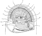
以下、図面を参照して本発明の実施の形態について説明する。図1は本発明の第1の実施の形態に係る超音波探触子の要部を示す部分断面斜視図である。図1において、ウインドウ1は略半球状の外形部を有し、被検体に対してシース(不図示)を介在し接触する。本実施の形態では、ウインドウ1の半径は13mm以下に形成されている。このウインドウ1内には音響伝搬媒質(不図示)が充填されており、これにより、超音波素子群2aより送受信される超音波は空気層を通過せず被検体へ良好に伝搬される。
【0015】
超音波素子組立体である超音波素子アセンブリ2はウインドウ1内に納まるような略半球状の形状及び大きさであって、超音波を送受信する超音波素子群2aと、超音波の焦点を機械的に定めるレンズ2bと、背面への超音波の発生を防ぐ背面緩衝材2c及び2dの多層構造で構成されている。これらは、音響インピーダンスを整合する整合層(図示せず)や超音波素子群2aの信号線(図示せず)を介して接合されている。超音波素子群2aは略半円の円周形状、本実施の形態では中心角が略180°の円弧形状を有し、この円弧に沿って超音波の送受信を行う複数の超音波素子が配列されている。この超音波素子群2aを電子走査することによって、中心角が略180°の円弧状の超音波素子群に相当する平面断層像を得ることができる。
【0016】
超音波素子アセンブリ2の内側は基台3により保持され、基台3は保持側が略180°の円弧状の形状に形成されているとともに、保持側の反対側に窪みが形成されている(図2参照)。回転軸4は略半円の円周形状を有する超音波素子群2aの直径に相当する位置に配置し、基台3の180°対向した両端部の2箇所で上記窪みを介して固定している(図3参照)。本実施の形態では、1箇所は回転軸固定手段である回転軸固定ねじ5で直接固定し、他の箇所は押さえ部材6を介してねじ(不図示)で固定しているが、固定方法に関しては両側とも押さえ部材でもよいし、ねじの代わりに接着剤を用いてもよい。また、本実施の形態では、回転軸4の断面形状は円筒形のものを用いたが、これに限られるものではなく、楕円形状、四角形状などであってもよい。ここで、超音波素子群がその内側を回転軸として揺動するように、回転軸4は中心角が略180°の円弧状の超音波素子アセンブリ2に干渉しない長さであるとともに、基台3に係合固定できる長さに設定している。
【0017】
駆動伝達軸7は回転軸4に固定され、また、図示省略されているが、この駆動伝達軸7をモータに連結して回転させることにより、回転軸4、基台3及び超音波素子アセンブリ2を一体として回転揺動させることができる。ここでは、駆動伝達軸7は、駆動伝達軸固定ねじとして機能する締結ねじ8で回転軸4に固定されている。軸受け部9は、回転軸4と基台3と超音波素子群2aが一体となって回転可能であるように、これらを保持している。本実施の形態では、軸受け部9に固定された2つのベアリング9a1、9a2で回転可能な状態で保持している。
【0018】
このように構成することによって、軸受け部9を含む回転揺動機構は、中心角が略180°の円弧状の超音波素子アセンブリ2の内側と基台3の両端部に効率よく構成できる。これにより、小型化を実現できるとともに、略180°にわたる範囲で電子走査と直交する方向への回転揺動を両立することができ、広範囲での立体像を得ることができ、被検体内での超音波診断画像を増やすことができる。
【0019】
<第2の実施の形態>
次に図2及び図3を参照して第2の実施の形態について説明する。ここで、図1では、小型化を実現するために回転軸4を円弧状の超音波素子アセンブリ2の内側に設けているので、回転軸4を取り付ける機構が重要となる。図2は第2の実施の形態に係る基台3の斜視図を示し、図3は第2の実施の形態における基台3と回転軸4の組み立て手順を示す。ここで、回転軸4は図3に示すように、基台3の内径より長く、外径より短く形成され、また、一端には基台3の内面に当接して軸方向を位置決めするための回転軸フランジ4aが形成されている。
【0020】
基台3には回転軸4の両端を取り付けるために、回転軸挿入方向に長い基台長穴3aと基台円筒穴3bが形成され、また、基台円筒穴3bの内側(基台3の窪み側)を回転軸挿入方向に基台端部から基台円筒穴3bまでを連結するように基台切り欠き溝3c(溝底面3d)が形成されている。本実施の形態では、基台円筒穴3bの内側が略半円筒状になるよう基台切欠き溝3cが形成されている。また、基台切り欠き溝3cの基台端部側には傾斜部3eを設けてある。
さらに本実施の形態では、超音波素子アセンブリ2の背面緩衝材2dが基台長穴3aの外側開口の一部を覆い、これにより回転軸4を基台長穴3aに挿入する際に回転軸4の先端が背面緩衝材2dに当接してそれ以上進まないようになっている。また、超音波素子アセンブリ2の基台長穴3a側の壁面、つまり基台長穴3aの外側の面3fから切り欠き溝3cの溝底面3dまでの長さl1より回転軸4の長さl2が長いために、組み立て時の手順、方向が正規と異なると組み立てが不可能になるとともに、正規の手順通り行うと回転軸4を支持する上で脱落しにくく、かつ小スペースの保持部を形成することができる。このように基台3を形成することにより、容易に、かつ確実に図1に示す回転軸4に取り付けることができる。以下その組み立て手順を図3を用いて説明する。
【0021】
図3は、本発明第2の実施の形態に係る組み立て手順を示す断面図であり、図3(a)、(b)、(c)の手順で組み立てを実施する。まず図3(a)に示すように、回転軸4の位置を固定し、基台3(及び基台3に固定された超音波素子アセンブリ2)を回転軸4に対して傾斜させて基台円筒穴3b側を開き、基台3の基台長穴3aを、回転軸4の回転軸フランジ4aが形成されていない方の一端に挿入する。ここで、基台長穴3aの長径方向は、回転軸4が挿入可能となるよう十分な長さに形成されている。
【0022】
基台長穴3aの挿入後、基台長穴3aの近傍を回転中心にして、基台3(及び超音波素子アセンブリ2)を図3(a)に示す矢印方向に回転させて基台円筒穴3b側を閉じる。ここで、基台3に基台切り欠き溝3cを形成しているため、基台3は回転軸4に干渉することなく基台3に形成された基台円筒穴3bが回転軸4に接触するまで基台円筒穴3b側を閉じることができる。また、本実施の形態では、基台3の基台切り欠き溝3cの基台円筒穴3bと対向する側に傾斜部を設けているため、基台3と回転軸4の干渉に対してより余裕を持たせることができる。
【0023】
つぎに図3(b)に示すように基台3(及び超音波素子アセンブリ2)を矢印で示すようにスライドさせて、回転軸4の他端を基台3の基台円筒穴3bの基台切り欠き溝3cが形成されていない領域まで挿入し、基台3と回転軸4の軸方向の相対位置を確実に規制する。軸方向の位置は、回転軸4に設けられた回転軸フランジ4aと基台3の内面が接触することで規制される。最後に図3(c)の矢印で示すように基台3と回転軸4の半径方向を固定する。ここで固定手段としては、ねじや専用の固定部材を用いてもよい。また接着材による固定を実施してもよい。
【0024】
以上、図2及び図3を用いて説明したように、基台3に回転軸挿入方向に長い基台長穴3aと、基台円筒穴3bと、基台円筒穴3bの内側を回転軸挿入方向に基台切り欠き溝3cを形成しているため、回転軸4を円弧状の超音波素子アセンブリ2の内側に設けていても、基台3及び超音波素子アセンブリ2と回転軸4の回転中心を確実に一致させるとともに、基台3及び超音波素子アセンブリ2を容易に回転軸4に組み立てることができる。
【0025】
<第3の実施の形態>
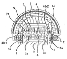
次に図4及び図5を参照して本発明の第3の実施の形態について説明する。図4は第3の実施の形態に用いられる回転軸4の斜視図である。回転軸4の一端には、第2の実施の形態と同様に、基台3の内面に当接して軸方向を位置決めするための回転軸フランジ4aが形成されている。第3の実施の形態では、さらに、回転軸4の長さl3は、第2の実施の形態における長さl2と同様、長さl1よりも長く、図5に示すように基台3の外径(=超音波素子アセンブリ2の内径)とほぼ同じであって基台3の内径寸法Aよりも十分長く、また、回転軸4の両端は半円筒形状に形成されて、円筒部の反対側には平面状の回転軸切り欠き面4b1、4b2が形成されている。
【0026】
基台3の構成は第2の実施の形態と同じであるが、基台3の基台長穴3aを回転軸4に組み込むときに、回転軸4の回転軸切り欠き面4b2が形成されていない方の円筒面を基台3に向き合うようにして基台長穴3aに挿入すると、回転軸4の先端が超音波素子アセンブリ2の内面に当接してそれ以上挿入することができず、逆に回転軸切り欠き面4b2が基台3に向き合うようにして基台長穴3aに挿入されると、回転軸4の先端が超音波素子アセンブリ2の内面に当接しないで先端面を乗り越えて空隙部10に入り込むことにより組み込み可能となるようにしている。
【0027】
このように回転軸4の両端に回転軸切り欠き面4b1、4b2を形成することにより、基台3を回転軸4へ組み込むとき、基台3を回転軸4へ固定する直前において基台3は回転軸4から脱落することがないため、固定時に基台3の脱落防止をする必要がなく作業が極めて容易になる。また基台3と回転軸4の接触部分を増加させることが可能なため安定した固定が可能になる。以下その組み立て手順を図5を用いて説明する。
【0028】
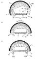
図5は、本発明の第3の実施の形態に係る組み立て手順を示す断面図であり、図5(a)、(b)、(c)、(d)の手順で組み立てを実施する。まず図5(a)に示すように、回転軸4を回転軸切り欠き面4b2、4b1がそれぞれ基台3の軸穴である基台長穴3a、基台円筒穴3bに向き合う方向になるように配置し、基台3(及び基台3に固定された超音波素子アセンブリ2)を回転軸4に傾斜させて基台円筒穴3b側を開いた状態で、回転軸4の回転軸フランジ4aが形成されていない方の回転軸切り欠き面4b2を基台3の基台長穴3aに対して挿入し、更に基台3の基台長穴3aと超音波素子アセンブリ2との間にできた空隙部10に回転軸切り欠き面4b2を挿入する。この空隙部10に回転軸切り欠き面4b2を挿入することで、回転軸4の全長が基台3の内径寸法Aよりも十分長くても組み込みが可能である。
【0029】
挿入後、空隙部10近傍を回転中心にして、基台3と超音波素子アセンブリ2を図5(a)に示す矢印方向に回転させて基台円筒穴3b側を閉じる。つぎに図5(b)に示すように基台3と超音波素子アセンブリ2を矢印方向にスライドさせて、回転軸4の他端を基台3の基台円筒穴3bの基台切り欠き溝3cが形成されていない領域まで挿入し、基台3と回転軸4の軸方向の相対位置を確実に規制する。軸方向の位置は、回転軸4に設けられた回転軸フランジ4aと基台3の内面が接触することで規制される。
【0030】
つぎに図5(c)に示すように、回転軸4を180°回転させる。ここで、基台3及び超音波素子アセンブリ2を回転させてもよい。これにより、図5(d)に示す180°の円弧形状の超音波素子アセンブリ2の内面がストッパになり、基台3(及び超音波素子アセンブリ2)は回転軸4から脱落しない。また基台3と回転軸4の接触部分を増加させ、図5(d)に矢印で示すように固定する際に、基台3と回転軸4との相対位置を安定させることができる。
【0031】
以上、図4及び図5を用いて説明したように、回転軸4の両端部近傍には平面状の回転軸切り欠き面4b1、4b2を形成し、基台3及び超音波素子アセンブリ2を回転軸4に組み込むときには、回転軸切り欠き面4b1、4b2が基台3に向き合う方向のみ組み込み可能となるようにしているため、基台3を回転軸4へ固定する直前において、基台3は回転軸4から脱落することがなく作業が極めて容易になる。また基台3と回転軸4の接触部分を増加させることが可能なため、安定した固定が可能になる。
【0032】
<第4の実施の形態>
図6は、本発明の第4の実施の形態に係る要部断面図である。ここで第3の実施の形態と重複する説明は割愛する。図6に示すように、回転軸4に回転軸フランジ4aが形成され、回転軸フランジ4aの軸方向外側は基台3に当接し、回転軸フランジ4aの軸方向内側は、軸受け部9に設けられたベアリング9aの内輪部と当接するように構成されている。本実施の形態では、基台3を回転軸4に組み込み、回転軸4と基台3を固定するときに、軸受け部9に設けられたベアリング9aにより回転軸フランジ4aの軸方向内側を固定している。
【0033】
このような構成にすることにより、基台3及び超音波素子アセンブリ2と回転軸4の軸方向の相対位置を一意的に規定できる。更には、押さえ部材であるベアリング9aの姿勢を一意的に規定でき安定した固定が実現できる。また、本実施の形態では、回転軸4の回転軸フランジ4aを、軸受け部9に固定されたベアリング9aの内輪部に当接させているため、基台3及び超音波素子アセンブリ2と軸受け部9との軸方向に相対位置を一意的に規定できる。さらに、本実施の形態では、駆動伝達軸7に設けた駆動伝達軸突起部7aをベアリング9aの内輪部に軸方向に当接するよう構成しているため、基台3及び超音波素子アセンブリ2と駆動伝達軸7との相対位置を一意的に規定できる。
【0034】
<第5の実施の形態>
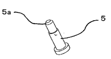
次に図7〜図10を参照して本発明の第5の実施の形態について説明する。図7は第5の実施の形態に係る回転軸4を示す斜視図であり、回転軸4の回転軸フランジ4aが形成されていない方の回転軸切り欠き面4b2の端部には45°の回転軸傾斜面4cが形成されている。また、図8は、本発明の第5の実施の形態に係る回転軸固定ねじ5を示す斜視図であり、回転軸固定ねじ5の先端に45°の回転軸固定ねじ傾斜面5aが形成されている。この回転軸傾斜面4cと回転軸固定ねじ傾斜面5aは、図9の要部断面図に示すように、お互いに当接する構成にしている。
【0035】
このような構成にすることによって、図10の要部拡大断面図に示すように、基台3を回転軸4に回転軸固定ねじ5で固定するとき、回転軸固定ねじ傾斜面5aの傾き角によって、軸方向の力Fxと半径方向の力Fyを自動的に発生させることができる。これにより、基台3と回転軸4は半径方向に固定されるとともに軸方向に相対的に付勢され、その結果、回転軸4の回転軸フランジ4aが基台3と押さえ部材6と当接する。したがって、基台3を回転軸4に組み込むとき、押圧作業をすることなく、回転軸固定ねじ5を締結するだけで、基台3及び超音波素子アセンブリ2と回転軸4の半径方向及び軸方向の相対位置を一意的に規定できる。更には、回転軸4が押さえ部材6と当接するため、回転軸4の姿勢を一意的に規定でき安定した固定が実現できる。
【0036】
<第6の実施の形態>
図11は、本発明の第6の実施の形態に係る要部斜視図である。ここで、保護板11は超音波素子アセンブリ2を保護するように構成され、基台3の両端部で保護板固定ねじ12で固定されている。また超音波素子信号線13とフィルム状超音波素子グランド板14を設け、このフィルム状超音波素子グランド板14を保護板固定ねじ12の近傍まで延長し、保護板11と基台3との間に介在させ、保護板11を基台3に固定させるときにフィルム状超音波素子グランド板14を基台3に導通させる構成にした。この構成により、狭いスペースで超音波信号を送受信する超音波素子の近傍で、確実に電気的グランドとフレームグランドの電位差を無くすことができ、したがって、超音波信号の耐ノイズ特性を向上させることができる。
【0037】
<第7の実施の形態>
図12は、本発明の第7の実施の形態に係る要部斜視図である。ここで、駆動部カバー15は、超音波素子アセンブリ2が機械揺動した際に、超音波素子信号線13が軸受け部9や駆動伝達機構(未図示)と接触することがないよう覆う構成にしている。この構成にすることによって、機械揺動における超音波素子信号線13の動作をスムーズにし、揺動負荷を低減するとともに、超音波素子信号線13の損傷を無くすことができる。
【0038】
【発明の効果】
以上説明したように請求項1に記載の発明によれば、略180°の円弧状の超音波素子組立体がその内側を回転軸として揺動するので、小型でかつ広範囲の立体画像を得ることができる。
請求項2に記載の発明によれば、略180°の円弧状の超音波素子組立体がその内側を回転軸として揺動する構成としても、超音波素子群を備えたアセンブリと回転軸の回転中心を確実に一致させることができるとともに、基台及び超音波素子アセンブリの回転軸への組み込みを容易にすることができる。
請求項3に記載の発明によれば、回転軸を支持する上で脱落しにくく、かつ小スペースの保持部を形成することができる。
請求項4に記載の発明によれば、超音波素子を保持する基台と回転軸の半径方向と軸方向の相対位置を一意的に規定でき、更には、押さえ部材の姿勢を一意的に規定でき安定した固定が実現できる。
請求項5に記載の発明によれば、基台を回転軸に組み込むときに押圧作業をすることなく、回転軸固定ねじを締結するだけで、超音波素子を保持する基台と回転軸の軸方向及び半径方向の相対位置を一意的に規定でき、更には、回転軸固定ねじの姿勢を一意的に規定でき安定した固定が実現できる。
請求項6に記載の発明によれば、狭いスペースで超音波信号を送受信する超音波素子の近傍で確実に電気的グランドとフレームグランドの電位差を無くすことができ、したがって、超音波信号の耐ノイズ特性を向上させることができる。
請求項7に記載の発明によれば、機械揺動する超音波素子信号線の動作をスムーズにし、揺動負荷を低減するとともに、超音波素子信号線の損傷を無くすことができる。
【図面の簡単な説明】
【図1】本発明の第1の実施の形態に係る超音波探触子の要部を示す部分断面斜視図
【図2】本発明の第2の実施の形態に係る基台を示す斜視図
【図3】本発明の第2の実施の形態に係る基台と回転軸の組み立て手順を示す断面図
【図4】本発明の第3の実施の形態に係る回転軸を示す斜視図
【図5】本発明の第3の実施の形態に係る組み立て手順を示す断面図
【図6】本発明の第4の実施の形態に係る要部断面図
【図7】本発明の第5の実施の形態に係る回転軸を示す斜視図
【図8】本発明の第5の実施の形態に係る回転軸固定ねじを示す斜視図
【図9】本発明の第5の実施の形態に係る要部断面図
【図10】本発明の第5の実施の形態に係る要部拡大断面図
【図11】本発明の第6の実施の形態に係る要部斜視図
【図12】本発明の第7の実施の形態に係る要部斜視図
【図13】従来の超音波探触子の要部斜視図
【符号の説明】
1 ウインドウ
2 超音波素子アセンブリ(超音波素子組立体)
2a 超音波素子群
2b レンズ
2c、2d 背面緩衝材
3 基台
3a 基台長穴
3b 基台円筒穴
3c 基台切り欠き溝
3d 溝底面
3e 傾斜部
3f 基台長穴の外側の面
4 回転軸
4a 回転軸フランジ
4b1、4b2 回転軸切り欠き面
4c 回転軸傾斜面
5 回転軸固定ねじ
5a 回転軸固定ねじ傾斜面
6 押さえ部材
7 駆動伝達軸
7a 駆動伝達軸突起部
8 駆動伝達軸固定ねじ
9 軸受け部
9a、9a1、9a2 ベアリング
10 空隙部
11 保護板
12 保護板固定ねじ
13 超音波素子信号線
14 フィルム状超音波素子グランド板
15 駆動部カバー
A 内径寸法[0001]
BACKGROUND OF THE INVENTION
The present invention relates to an ultrasonic probe of an ultrasonic medical diagnostic apparatus capable of obtaining a stereoscopic image by combining electronic scanning and mechanical scanning.
[0002]
[Prior art]
In recent years, in the field of ultrasonic probes of ultrasonic medical diagnostic apparatuses, a technique has been developed that obtains a stereoscopic image by electronic scanning with a group of convex ultrasonic elements and mechanical scanning in a direction orthogonal to the electronic scanning. (See, for example, Patent Document 1 below).
[0003]
FIG. 13 shows a perspective view of the main part of such a conventional transabdominal ultrasonic probe. In FIG. 13, the
[0004]
[Patent Document 1]
Japanese Patent Publication No. 7-38851 (Example)
[0005]
[Problems to be solved by the invention]
However, a conventional ultrasonic probe that obtains a stereoscopic image by a combination of electronic scanning and mechanical scanning has a large outer size, a narrow viewing angle by electronic scanning, and a stereoscopic image in a limited range. On the other hand, in recent years, there has been a demand for a compact, wide electronic viewing angle and a wide range of 3D images centering on an ultrasound probe used in a subject.
[0006]
The present invention solves such a conventional problem, and an object thereof is to provide an ultrasonic probe that is small and can obtain a wide range of stereoscopic images.
[0007]
[Means for Solving the Problems]
In order to achieve the above object, the present invention provides ultrasonic element assemblies arranged in an arc shape;
While holding the inside of the ultrasonic element assembly arranged in the arc shape, a base provided with a depression on the inner side opposite to the holding side;
Rotation shafts fixed at two locations in the vicinity of opposite end positions of the base so as to pass through the arc center of the ultrasonic element assembly inside the arc-shaped ultrasonic element assembly;
A bearing portion that rotatably holds the rotating shaft in a recess portion inside the base;
The cylindrical hole is formed on the inner wall of the base on the cylindrical hole side from the end of the base by forming a long hole and a cylindrical hole at each position where both ends of the rotating shaft of the base are fixed. It was set as the structure which formed the notch groove which connects up to .
With this configuration, since the arc-shaped ultrasonic element assembly of approximately 180 ° swings its inner as a rotation axis, it is possible to obtain a compact and a wide range of three-dimensional image, of approximately 180 ° arcuate super Even when the ultrasonic element assembly swings around the rotation axis, the assembly including the ultrasonic element group and the rotation center of the rotation axis can be reliably aligned, and the base and the ultrasonic element assembly Incorporation into the rotating shaft can be facilitated .
[0009]
In the ultrasonic probe of the present invention, both ends of the rotation shaft are formed in a semicylindrical shape, and the notch is formed from the inner wall surface of the ultrasonic element assembly that covers a part of the opening of the elongated hole portion. The length of the rotating shaft is longer than the length of the groove to the groove bottom surface.
With this configuration, when the base is assembled to the rotating shaft, it can be assembled only when the flat portion of the rotating shaft faces the base, and the rotating shaft does not fall off the base during the mounting. Work becomes extremely easy. Further, by increasing the contact portion between the base and the rotating shaft, it is possible to secure the fixing. Furthermore, with this configuration, it is possible to form a holding portion with a small space that is difficult to drop off when supporting the rotating shaft.
[0010]
The ultrasonic probe according to the present invention further includes a pressing member that contacts and fixes the rotating shaft to the base, and contacts the inner surface of the base and the side surface of the pressing member on the rotating shaft. It was set as the structure which formed the flange part.
With this configuration, the relative position of the base holding the ultrasonic element and the rotation shaft in the radial direction and the axial direction can be uniquely defined, and furthermore, the posture of the pressing member can be uniquely defined to realize stable fixation. .
[0011]
In the ultrasonic probe of the present invention, a surface inclined with respect to the axial direction and the radial direction is formed at an end of the rotating shaft on the elongated hole side, and an inclined surface corresponding to the inclined surface is formed. The rotating shaft fixing means is provided.
With this configuration, the relative position of the base holding the ultrasonic element and the rotary shaft in the axial direction and the radial direction can be obtained simply by fastening the rotary shaft fixing screw without pressing when the base is incorporated into the rotary shaft. Can be uniquely defined, and furthermore, the posture of the rotary shaft fixing screw can be uniquely defined, and stable fixation can be realized.
[0012]
In the ultrasonic probe of the present invention, a ground member is disposed between a thin plate provided on a side surface of the ultrasonic element assembly and the base, and the ground potential of the ultrasonic element assembly The base was configured to have the same potential.
With this configuration, the potential difference between the electrical ground and the frame ground can be reliably eliminated in the vicinity of the ultrasonic element that transmits and receives the ultrasonic signal in a narrow space, and therefore the noise resistance characteristics of the ultrasonic signal can be improved. .
[0013]
Further, the ultrasonic probe of the present invention has a swing mechanism cover so that the signal line does not come into contact with the swing mechanism in the recess inside the base when the ultrasonic element assembly swings. The configuration was provided.
With this configuration, it is possible to smooth the operation of the ultrasonic element signal line that mechanically swings, reduce the swing load, and eliminate damage to the ultrasonic element signal line.
[0014]
DETAILED DESCRIPTION OF THE INVENTION
<First Embodiment>
Embodiments of the present invention will be described below with reference to the drawings. FIG. 1 is a partial cross-sectional perspective view showing the main part of the ultrasonic probe according to the first embodiment of the present invention. In FIG. 1, a window 1 has a substantially hemispherical outer shape, and contacts a subject via a sheath (not shown). In the present embodiment, the radius of the window 1 is formed to be 13 mm or less. The window 1 is filled with an acoustic propagation medium (not shown), so that the ultrasonic waves transmitted / received from the ultrasonic element group 2a are favorably propagated to the subject without passing through the air layer.
[0015]
The
[0016]
The inner side of the
[0017]
The
[0018]
With this configuration, the rotation and swing mechanism including the bearing
[0019]
<Second Embodiment>
Next, a second embodiment will be described with reference to FIGS. Here, in FIG. 1, since the
[0020]
In order to attach both ends of the
Further, in the present embodiment, the back cushioning material 2d of the
[0021]
FIG. 3 is a cross-sectional view showing an assembling procedure according to the second embodiment of the present invention, and assembling is performed according to the procedure of FIGS. 3 (a), (b), and (c). First, as shown in FIG. 3A, the position of the
[0022]
After the insertion of the base
[0023]
Next, as shown in FIG. 3 (b), the base 3 (and the ultrasonic element assembly 2) is slid as indicated by an arrow, and the other end of the
[0024]
As described above with reference to FIGS. 2 and 3, the
[0025]
<Third Embodiment>
Next, a third embodiment of the present invention will be described with reference to FIGS. FIG. 4 is a perspective view of the
[0026]
The configuration of the
[0027]
In this way, when the
[0028]
FIG. 5 is a cross-sectional view showing an assembling procedure according to the third embodiment of the present invention, and the assembling is performed according to the procedure of FIGS. 5 (a), (b), (c), and (d). First, as shown in FIG. 5A, the
[0029]
After the insertion, the
[0030]
Next, as shown in FIG.5 (c), the
[0031]
As described above with reference to FIGS. 4 and 5, planar rotation shaft notch surfaces 4 b 1 and 4 b 2 are formed in the vicinity of both ends of the
[0032]
<Fourth embodiment>
FIG. 6 is a cross-sectional view of a main part according to the fourth embodiment of the present invention. Here, the description overlapping with the third embodiment is omitted. As shown in FIG. 6, a
[0033]
With this configuration, the relative position in the axial direction of the
[0034]
<Fifth embodiment>
Next, a fifth embodiment of the present invention will be described with reference to FIGS. FIG. 7 is a perspective view showing the
[0035]
With this configuration, when the
[0036]
<Sixth Embodiment>
FIG. 11 is a perspective view of relevant parts according to the sixth embodiment of the present invention. Here, the
[0037]
<Seventh embodiment>
FIG. 12 is a perspective view of relevant parts according to the seventh embodiment of the present invention. Here, the
[0038]
【The invention's effect】
As described above, according to the first aspect of the present invention, since the approximately 180 ° arc-shaped ultrasonic element assembly swings around the rotation axis, a small and wide-range stereoscopic image can be obtained. Can do.
According to the second aspect of the present invention, the assembly including the ultrasonic element group and the rotation of the rotation shaft can be configured such that the substantially 180 ° arc-shaped ultrasonic element assembly swings around the rotation axis. The centers can be surely matched, and the base and the ultrasonic element assembly can be easily incorporated into the rotation shaft.
According to the third aspect of the present invention, it is possible to form a holding portion with a small space that is difficult to drop off when supporting the rotating shaft.
According to the fourth aspect of the present invention, the relative positions of the base holding the ultrasonic element and the rotation shaft in the radial direction and the axial direction can be uniquely defined, and the posture of the pressing member can be uniquely defined. And stable fixation can be realized.
According to the fifth aspect of the present invention, the base for holding the ultrasonic element and the axis of the rotary shaft can be obtained by simply fastening the rotary shaft fixing screw without pressing when the base is incorporated into the rotary shaft. The relative position in the direction and the radial direction can be uniquely defined, and further, the posture of the rotary shaft fixing screw can be uniquely defined, and stable fixation can be realized.
According to the sixth aspect of the present invention, the potential difference between the electrical ground and the frame ground can be reliably eliminated in the vicinity of the ultrasonic element that transmits and receives the ultrasonic signal in a narrow space. Characteristics can be improved.
According to the seventh aspect of the present invention, the operation of the ultrasonic element signal line that mechanically swings can be made smooth, the swing load can be reduced, and damage to the ultrasonic element signal line can be eliminated.
[Brief description of the drawings]
FIG. 1 is a partial cross-sectional perspective view showing a main part of an ultrasonic probe according to a first embodiment of the present invention. FIG. 2 is a perspective view showing a base according to a second embodiment of the present invention. FIG. 3 is a cross-sectional view showing a procedure for assembling a base and a rotating shaft according to a second embodiment of the present invention. FIG. 4 is a perspective view showing a rotating shaft according to the third embodiment of the present invention. 5 is a cross-sectional view showing an assembling procedure according to a third embodiment of the present invention. FIG. 6 is a cross-sectional view of a main part according to a fourth embodiment of the present invention. FIG. 8 is a perspective view showing a rotating shaft fixing screw according to a fifth embodiment of the present invention. FIG. 9 is a cross-sectional view of a main part according to the fifth embodiment of the present invention. FIG. 10 is an enlarged cross-sectional view of the main part according to the fifth embodiment of the present invention. FIG. 11 is a perspective view of the main part according to the sixth embodiment of the present invention. Main part perspective view of a main part perspective view [13] Conventional ultrasonic probe according to the embodiment EXPLANATION OF REFERENCE NUMERALS
1
2a Ultrasonic element group 2b Lens 2c, 2d Back cushioning
Claims (6)
前記円弧状に配列された超音波素子組立体の内側を保持するとともに、前記保持側と反対の内側に窪みを設けた基台と、
前記円弧状の超音波素子組立体の内側で前記超音波素子組立体の円弧中心を通るように、前記基台の対向した両端位置の近傍の2箇所で固定された回転軸と、
前記基台の内側の窪み部で前記回転軸を回転可能に保持する軸受け部とを、
有し、前記基台の前記回転軸の両端を固定する各位置にそれぞれ長穴部と円筒穴部を形成して前記円筒穴部側の前記基台の内壁に前記基台端部から前記円筒穴部までを連結する切り欠き溝を形成した超音波探触子。Ultrasonic element assemblies arranged in an arc shape;
While holding the inside of the ultrasonic element assembly arranged in the arc shape, a base provided with a depression on the inner side opposite to the holding side;
Rotation shafts fixed at two locations in the vicinity of opposite end positions of the base so as to pass through the arc center of the ultrasonic element assembly inside the arc-shaped ultrasonic element assembly;
A bearing portion that rotatably holds the rotating shaft in a recess portion inside the base;
Yes, and the cylindrical bore across the base of the inner wall of form respective slot portion and the cylindrical bore at each position fixing said cylindrical bore side of the rotary shaft of the base from the base end portion Ultrasonic probe with notched grooves that connect up to the part .
Priority Applications (1)
| Application Number | Priority Date | Filing Date | Title |
|---|---|---|---|
| JP2003156287A JP4260552B2 (en) | 2003-06-02 | 2003-06-02 | Ultrasonic probe |
Applications Claiming Priority (1)
| Application Number | Priority Date | Filing Date | Title |
|---|---|---|---|
| JP2003156287A JP4260552B2 (en) | 2003-06-02 | 2003-06-02 | Ultrasonic probe |
Publications (2)
| Publication Number | Publication Date |
|---|---|
| JP2004357742A JP2004357742A (en) | 2004-12-24 |
| JP4260552B2 true JP4260552B2 (en) | 2009-04-30 |
Family
ID=34050413
Family Applications (1)
| Application Number | Title | Priority Date | Filing Date |
|---|---|---|---|
| JP2003156287A Expired - Fee Related JP4260552B2 (en) | 2003-06-02 | 2003-06-02 | Ultrasonic probe |
Country Status (1)
| Country | Link |
|---|---|
| JP (1) | JP4260552B2 (en) |
Families Citing this family (1)
| Publication number | Priority date | Publication date | Assignee | Title |
|---|---|---|---|---|
| JP4532294B2 (en) * | 2005-01-19 | 2010-08-25 | パナソニック株式会社 | Ultrasonic probe |
-
2003
- 2003-06-02 JP JP2003156287A patent/JP4260552B2/en not_active Expired - Fee Related
Also Published As
| Publication number | Publication date |
|---|---|
| JP2004357742A (en) | 2004-12-24 |
Similar Documents
| Publication | Publication Date | Title |
|---|---|---|
| US5771896A (en) | Compact rotationally steerable ultrasound transducer | |
| US6423008B1 (en) | Ultrasonic probe | |
| US5305755A (en) | Ultrasonic probe, having transducer array capable of turning around its aperture axis and having a convex lens comprising a viscous resin | |
| US20060074316A1 (en) | Ultrasonic probe | |
| JP4260552B2 (en) | Ultrasonic probe | |
| JPH0673521B2 (en) | Ultrasonic transducer probe assembly | |
| JP2538764B2 (en) | Motor deformation prevention structure for vibration generation | |
| JP3150613B2 (en) | Ultrasound imaging catheter | |
| JP7403358B2 (en) | ultrasonic probe | |
| JP4532294B2 (en) | Ultrasonic probe | |
| JPH049149A (en) | Ultrasonic probe for picking up three-dimensional data | |
| JPH11332867A (en) | Ultrasonic endoscope apparatus | |
| JPS6227913A (en) | Ultrasonic endoscope | |
| CN114123846B (en) | Vibration type driving device and image pickup apparatus using the same | |
| JP2761175B2 (en) | Coreless motor device | |
| JP2004290272A (en) | Ultrasonic probe | |
| JP7522634B2 (en) | Non-contact communication module and rotary communication device equipped with the same | |
| JPH07289551A (en) | Ultrasonic diagnostic equipment | |
| JPS6125538A (en) | Ultrasonic endoscope | |
| JP6767949B2 (en) | Ultrasonic probe | |
| JPH07395A (en) | Catheter type ultrasonic probe | |
| JPH04319662A (en) | Ultrasonic probe | |
| JPH114827A (en) | Ultrasonic diagnostic device in body cavity | |
| JP2002253543A (en) | X-ray ct device | |
| JPH11192224A (en) | Ultrasonic probe |
Legal Events
| Date | Code | Title | Description |
|---|---|---|---|
| A621 | Written request for application examination |
Free format text: JAPANESE INTERMEDIATE CODE: A621 Effective date: 20060208 |
|
| A977 | Report on retrieval |
Free format text: JAPANESE INTERMEDIATE CODE: A971007 Effective date: 20081001 |
|
| A131 | Notification of reasons for refusal |
Free format text: JAPANESE INTERMEDIATE CODE: A131 Effective date: 20081007 |
|
| A521 | Written amendment |
Free format text: JAPANESE INTERMEDIATE CODE: A523 Effective date: 20081205 |
|
| TRDD | Decision of grant or rejection written | ||
| A01 | Written decision to grant a patent or to grant a registration (utility model) |
Free format text: JAPANESE INTERMEDIATE CODE: A01 Effective date: 20090113 |
|
| A01 | Written decision to grant a patent or to grant a registration (utility model) |
Free format text: JAPANESE INTERMEDIATE CODE: A01 |
|
| A61 | First payment of annual fees (during grant procedure) |
Free format text: JAPANESE INTERMEDIATE CODE: A61 Effective date: 20090204 |
|
| FPAY | Renewal fee payment (event date is renewal date of database) |
Free format text: PAYMENT UNTIL: 20120220 Year of fee payment: 3 |
|
| R150 | Certificate of patent or registration of utility model |
Ref document number: 4260552 Country of ref document: JP Free format text: JAPANESE INTERMEDIATE CODE: R150 Free format text: JAPANESE INTERMEDIATE CODE: R150 |
|
| FPAY | Renewal fee payment (event date is renewal date of database) |
Free format text: PAYMENT UNTIL: 20130220 Year of fee payment: 4 |
|
| FPAY | Renewal fee payment (event date is renewal date of database) |
Free format text: PAYMENT UNTIL: 20130220 Year of fee payment: 4 |
|
| FPAY | Renewal fee payment (event date is renewal date of database) |
Free format text: PAYMENT UNTIL: 20140220 Year of fee payment: 5 |
|
| S111 | Request for change of ownership or part of ownership |
Free format text: JAPANESE INTERMEDIATE CODE: R313113 |
|
| R350 | Written notification of registration of transfer |
Free format text: JAPANESE INTERMEDIATE CODE: R350 |
|
| LAPS | Cancellation because of no payment of annual fees |