JP4259552B2 - Image forming system - Google Patents
Image forming system Download PDFInfo
- Publication number
- JP4259552B2 JP4259552B2 JP2006222246A JP2006222246A JP4259552B2 JP 4259552 B2 JP4259552 B2 JP 4259552B2 JP 2006222246 A JP2006222246 A JP 2006222246A JP 2006222246 A JP2006222246 A JP 2006222246A JP 4259552 B2 JP4259552 B2 JP 4259552B2
- Authority
- JP
- Japan
- Prior art keywords
- cover
- image
- image data
- bundle
- spine
- Prior art date
- Legal status (The legal status is an assumption and is not a legal conclusion. Google has not performed a legal analysis and makes no representation as to the accuracy of the status listed.)
- Expired - Fee Related
Links
- 238000003860 storage Methods 0.000 claims description 15
- 238000001514 detection method Methods 0.000 claims description 6
- 238000000034 method Methods 0.000 description 23
- 230000006870 function Effects 0.000 description 15
- 230000008569 process Effects 0.000 description 14
- 238000005520 cutting process Methods 0.000 description 12
- 238000012545 processing Methods 0.000 description 11
- 238000010586 diagram Methods 0.000 description 10
- 238000003825 pressing Methods 0.000 description 9
- 239000000853 adhesive Substances 0.000 description 8
- 230000001070 adhesive effect Effects 0.000 description 7
- 238000004891 communication Methods 0.000 description 7
- 108091008695 photoreceptors Proteins 0.000 description 7
- 230000015572 biosynthetic process Effects 0.000 description 6
- 230000008859 change Effects 0.000 description 4
- 238000012546 transfer Methods 0.000 description 4
- 238000009966 trimming Methods 0.000 description 4
- 238000006243 chemical reaction Methods 0.000 description 2
- 238000004140 cleaning Methods 0.000 description 2
- 239000011248 coating agent Substances 0.000 description 2
- 238000000576 coating method Methods 0.000 description 2
- 238000005304 joining Methods 0.000 description 2
- 230000003287 optical effect Effects 0.000 description 2
- 238000004026 adhesive bonding Methods 0.000 description 1
- 238000003705 background correction Methods 0.000 description 1
- 230000005540 biological transmission Effects 0.000 description 1
- 230000006835 compression Effects 0.000 description 1
- 238000007906 compression Methods 0.000 description 1
- 238000011161 development Methods 0.000 description 1
- 230000004907 flux Effects 0.000 description 1
- 230000007246 mechanism Effects 0.000 description 1
- 230000004048 modification Effects 0.000 description 1
- 238000012986 modification Methods 0.000 description 1
- 238000012805 post-processing Methods 0.000 description 1
- 230000004044 response Effects 0.000 description 1
- 238000000926 separation method Methods 0.000 description 1
- 230000007480 spreading Effects 0.000 description 1
- 238000003892 spreading Methods 0.000 description 1
- 238000011144 upstream manufacturing Methods 0.000 description 1
Images


Landscapes
- Paper Feeding For Electrophotography (AREA)
- Image Processing (AREA)
- Facsimiles In General (AREA)
- Editing Of Facsimile Originals (AREA)
Description
本発明は、冊子状原稿の読み取りを行う読取装置及びこの読取装置を有する画像形成システムに関し、特に用紙束を表紙でコの字状に覆い製本する画像形成システム及びこれに用いる読取装置に関する。 The present invention relates to a reading apparatus that reads a booklet document and an image forming system including the reading apparatus, and more particularly to an image forming system that covers a bundle of sheets in a U-shape with a cover and binds to the reading apparatus.
従来、複写機、ファクシミリ、プリンタ等の電子写真方式の画像形成装置において、本や雑誌などの冊子状原稿の複写を行う場合がある。 Conventionally, in an electrophotographic image forming apparatus such as a copying machine, a facsimile, or a printer, a booklet document such as a book or a magazine may be copied.
見開きの冊子状原稿の読み取り方式としては、2ページ分の見開き原稿を1回のスキャンで左右1ページに別々に読み取りをする機能として、所謂ページ連写機能を備えたものが一般に知られている。 As a method for reading a two-page spread booklet document, a method having a so-called page continuous shooting function is generally known as a function of separately reading two pages of a spread document into one page on the left and right in one scan. .
従来のページ連写機能の具体的な例について図を用いて説明する。図14は、ページ連写機能を用いて読み取った冊子状原稿と画像データとの関係を示す説明図である。図14(a)は左綴じ(左開きともいう)の冊子状原稿、図14(b)は右綴じ(右開きともいう)の冊子状原稿である。 A specific example of a conventional page continuous shooting function will be described with reference to the drawings. FIG. 14 is an explanatory diagram showing the relationship between a booklet document read using the page continuous shooting function and image data. FIG. 14A shows a booklet original with left binding (also referred to as left opening), and FIG. 14B shows a booklet original with right binding (also referred to as right opening).
図14(c)は図14(a)、図14(b)の冊子状原稿をページ1とページ2、ページ3とページ4、ページN−1とページNをそれぞれ見開いた状態で原稿台に載せ各々1回のスキャンによりページ1からページNまでを別々の画像データとして読み取りをした状態を示す図である。同図に示すようにページ連写を用いるとNページの冊子原稿に対してN/2回のスキャンでNページの画像データを得ることができる。
FIG. 14 (c) shows the booklet document of FIGS. 14 (a) and 14 (b) on the document table with the
また冊子状原稿の出力方式としては、複写機やプリンタ等で画像を形成した複数枚の用紙の束(本身用紙ともいう)を表紙用紙でコの字状にくるみ、用紙の束の背部と表紙用紙を糊付けすることにより簡易的にくるみ製本処理を行う画像形成システムが知られている(特許文献1参照)。 As a booklet-type document output method, a bundle of multiple sheets (also called body sheets) on which an image is formed by a copier or printer is wrapped in a U-shape with a cover sheet, and the back of the stack of sheets and the cover sheet An image forming system that performs simple case binding processing by gluing sheets is known (see Patent Document 1).
製本装置により形成された本の一例を図15に示す。図15(a)は表紙用紙S2が折られていない状態を示し、図15(b)は表紙用紙S2が折られた状態を示す。S3は複数枚の本身用紙S1の束と表紙用紙S2により構成されており、本身用紙S1の束を表紙用紙S2でコの字状に覆うような形態になっている。S3のような形態をくるみ本ともいう。表紙用紙S2は図15(a)に示すようにオモテ表紙領域Fと背表紙領域Sとウラ表紙領域Bを有する。
くるみ製本処理を行う画像形成システムにおいて冊子状原稿の複写を行う場合に、出力として、冊子状原稿と同じ出力を得ることが目的となる場合がある。 When a booklet document is copied in an image forming system that performs case binding processing, there is a case where the output is the same as that of a booklet document.
しかし、従来のページ連写機能を用いると、読み取りサイズはページサイズの2倍に設定されてしまう。そのため、冊子状原稿の表紙を見開きで読み取りを行う場合に、ページサイズの2倍に対し、更に背表紙の幅相当分サイズが長くなるのに対して読み取りサイズを適正に合わせることができないという問題がある。また表紙を、背表紙を含めた、オモテ表紙、背表紙、ウラ表紙のそれぞれに3分割して読み取りを行いたいという要望に対し、従来のページ連写機能では2分割しかできないため背表紙の読み取りを適正に行えないという問題がある。 However, when the conventional page continuous shooting function is used, the reading size is set to twice the page size. For this reason, when reading a booklet document cover with a two-page spread, the read size cannot be adjusted properly, although the size corresponding to the width of the back cover is longer than twice the page size. There is. In addition, in response to the desire to read the front cover, including the back cover, into a front cover, a back cover, and a back cover in three parts, the conventional page continuous shooting function only allows two parts to be read. There is a problem that cannot be performed properly.
また読み取りを行う冊子と出力の冊子において、用紙の厚さが異なるために冊子両者間で背表紙の厚さ(背表紙幅)が異なってしまう場合がある。その場合には冊子状原稿の背表紙画像を出力の冊子の背表紙に適正に配置できないという問題がある。 In addition, since the booklet to be read and the output booklet have different sheet thicknesses, the thickness of the spine (back cover width) may be different between the two. In this case, there is a problem that the back cover image of the booklet-like document cannot be properly arranged on the back cover of the output booklet.
本発明は上記問題に鑑み、冊子状原稿の複写を行う場合に、背表紙を含めて適正に読み取り、及び出力が可能な画像形成システムを得ることを目的とするものである。 In view of the above problems, when performing a copy of the booklet-like document, including the spine read properly, and it is an object to obtain the images forming system capable of outputting.
1.各種の入力がなされる入力手段と、
冊子状原稿を読み取り可能な画像読取手段と、
読み取った画像データを記憶する記憶手段と、
見開きの冊子状原稿の読み取りモードを選択する読取モード選択手段と、
前記読取モード選択手段で、表紙見開き読取モードが選択されると、前記入力手段から入力された冊子状原稿の背表紙幅及びページサイズ、の情報に基づき見開きの冊子状原稿をオモテ表紙、背表紙、ウラ表紙の画像データとして読み取りを行うように制御する読取制御手段と、
本身用紙及び表紙用紙に画像データに基づいて画像形成を行う画像形成手段と、
画像形成される本身用紙の束の厚さ情報を取得する束厚取得手段と、を有する画像形成システムであって、
前記束厚取得手段により取得した本身用紙の束の厚さ情報と前記記憶手段に記憶された背表紙の画像幅の情報とを比較する比較手段と、
前記比較手段による比較の結果、背表紙の画像幅が本身用紙の束の厚さよりも大きいと判断されると、表紙用紙の背表紙領域の範囲内に背表紙の画像が収まるように背表紙の画像データのトリミングを行い、背表紙の画像幅が本身用紙の束の厚さよりも小さいと判断されると、表紙用紙の背表紙領域の余白部分に白紙画像データを追加して、オモテ表紙の画像データとウラ表紙の画像データと合成して表紙画像データの配置を行う配置手段とを有し、
前記配置手段で配置された表紙画像データに基づき、表紙用紙に前記画像形成手段で画像形成することを特徴とする画像形成システム。
1. Input means for making various inputs;
Image reading means capable of reading a booklet document;
Storage means for storing the read image data;
A reading mode selection means for selecting a reading mode of a booklet document with a spread;
When the cover-page spread reading mode is selected by the reading mode selection means, the spread booklet original is read as a front cover and a back cover based on the information on the spine width and page size of the booklet original input from the input means. Reading control means for controlling reading as image data of the back cover;
Image forming means for forming an image on the body paper and the cover paper based on the image data;
An image forming system comprising: a bundle thickness acquisition unit that acquires thickness information of a bundle of body sheets to be imaged;
A comparison unit that compares the thickness information of the bundle of body sheets acquired by the bundle thickness acquisition unit with the information on the image width of the spine cover stored in the storage unit;
As a result of the comparison by the comparison means, if it is determined that the image width of the spine is larger than the thickness of the stack of body paper, If the image data is trimmed and the image width of the spine cover is determined to be smaller than the thickness of the bundle of body paper, blank image data is added to the margin of the spine cover area of the cover paper, and the front cover image An arrangement means for arranging the cover image data by combining the data and the image data of the back cover,
An image forming system, wherein the image forming unit forms an image on a cover sheet based on the cover image data arranged by the arranging unit.
2.各種の入力がなされる入力手段と、
冊子状原稿を読み取り可能な画像読取手段と、
原稿のサイズを検知する原稿サイズ検知手段と、
読み取った画像データを記憶する記憶手段と、
見開きの冊子状原稿の読み取りモードを選択する読取モード選択手段と、
前記読取モード選択手段で、表紙見開き読取モードが選択されると、前記原稿サイズ検知手段により検知された原稿サイズ情報と前記入力手段から入力された冊子状原稿のページサイズ、の情報に基づき見開きの冊子状原稿をオモテ表紙、背表紙、ウラ表紙の画像データとして読み取りを行うように制御する読取制御手段と、
本身用紙及び表紙用紙に画像データに基づいて画像形成を行う画像形成手段と、
画像形成される本身用紙の束の厚さ情報を取得する束厚取得手段と、を有する画像形成システムであって、
前記束厚取得手段により取得した本身用紙の束の厚さ情報と前記記憶手段に記憶された背表紙の画像幅の情報とを比較する比較手段と、
前記比較手段による比較の結果、背表紙の画像幅が本身用紙の束の厚さよりも大きいと判断されると、表紙用紙の背表紙領域の範囲内に背表紙の画像が収まるように背表紙の画像データのトリミングを行い、背表紙の画像幅が本身用紙の束の厚さよりも小さいと判断されると、表紙用紙の背表紙領域の余白部分に白紙画像データを追加して、オモテ表紙の画像データとウラ表紙の画像データと合成して表紙画像データの配置を行う配置手段とを有し、
前記配置手段で配置された表紙画像データに基づき、表紙用紙に前記画像形成手段で画像形成することを特徴とする画像形成システム。
2. Input means for making various inputs;
Image reading means capable of reading a booklet document;
A document size detecting means for detecting the size of the document;
Storage means for storing the read image data;
A reading mode selection means for selecting a reading mode of a booklet document with a spread;
In the reading mode selecting means, cover the spread reading mode is selected, spread on the basis of the document size page size of the booklet-like document that is input from the detection knowledge original size information input means by detecting means, the information Reading control means for controlling to read the booklet original as image data of the front cover, the back cover, and the back cover,
Image forming means for forming an image on the body paper and the cover paper based on the image data;
An image forming system comprising: a bundle thickness acquisition unit that acquires thickness information of a bundle of body sheets to be imaged;
A comparison unit that compares the thickness information of the bundle of body sheets acquired by the bundle thickness acquisition unit with the information on the image width of the spine cover stored in the storage unit;
As a result of the comparison by the comparison means, if it is determined that the image width of the spine is larger than the thickness of the stack of body paper, the spine image of the spine is fit so that the spine image fits within the range of the spine area of the cover paper. If the image data is trimmed and the image width of the spine cover is determined to be smaller than the thickness of the bundle of body paper, blank image data is added to the margin of the spine cover area of the cover paper, and the front cover image An arrangement means for arranging the cover image data by combining the data and the image data of the back cover,
An image forming system, wherein the image forming unit forms an image on a cover sheet based on the cover image data arranged by the arranging unit.
3.表紙用紙サイズ情報を取得する表紙用紙サイズ情報取得手段を備えており、
前記配置手段が、前記表紙用紙サイズ情報取得手段から取得した表紙用紙サイズ情報に基づき、オモテ表紙の画像データを表紙用紙領域の一方の端部を基準として配置し、ウラ表紙の画像データを他方の端部を基準として配置し、背表紙の画像データを表紙用紙領域の中央位置に配置することを特徴とする1又は2に記載の画像形成システム。
3. Cover page size information acquisition means for acquiring cover page size information is provided,
Based on the cover sheet size information acquired from the cover sheet size information acquisition unit , the arrangement unit arranges the image data of the front cover on the basis of one end of the cover sheet region, and the image data of the back cover is set on the other side. the end is disposed as a reference, an image forming system according to image data of the spine to 1 or 2, wherein the Turkey be placed in a central position of the cover sheet region.
4.前記表紙用紙サイズ情報は、前記入力手段から入力された冊子状原稿の背表紙幅の情報と冊子状原稿のページサイズ情報であり、前記背表紙幅と前記ページサイズを用いて表紙サイズを決定することを特徴とする、3に記載の画像形成システム。
4). The cover sheet size information is the page size information of the spine width of the information and booklet original booklet document inputted from the input means, to determine a cover size using the spine width and the
5.前記束厚取得手段は、本身用紙の1枚あたりの厚さと、本身用紙の束の枚数とを乗じた値を、本身用紙の束の厚さ情報として用いることを特徴とする1乃至4の何れか1に記載の画像形成システム。 5. The bundle acquisition means, any the thickness per sheet of the present body sheets, the value obtained by multiplying the number of bundle of the body sheets, of 1 to 4, which comprises using as the thickness information of the bundle of the body sheet the image forming system according to one.
6.前記画像形成手段で画像形成された本身用紙の束を表紙用紙でコの字状に覆って冊子を作成する製本手段を有することを特徴とする請求項1乃至5の何れか1項に記載の画像形成システム。
6). 6. The bookbinding unit according to
本発明によれば、冊子状原稿の複写を行う場合に、背表紙を含めて適正に冊子状原稿の読み取り、及び出力が可能な画像形成システムを得ることが可能となる。
According to the present invention, when performing a copy of the booklet-like document, it is possible to obtain readings of proper booklet document including spine, and the images forming system capable output.
図1は、画像形成システムの中央断面図である。 FIG. 1 is a central sectional view of the image forming system.
画像形成システムは画像形成装置A及び製本装置(製本手段)Bを有する。画像形成装置Aは電子写真方式により用紙に画像を形成するものであり、画像形成手段A1、画像読取手段(画像読み取り装置)A30、を有する。 The image forming system includes an image forming apparatus A and a bookbinding apparatus (bookbinding means) B. The image forming apparatus A forms an image on a sheet by an electrophotographic method, and includes an image forming unit A1 and an image reading unit (image reading device) A30.
画像形成手段A1において、1はドラム状の感光体、2は感光体1を一様に帯電する帯電装置、3は帯電された感光体1を像露光する露光装置、4は露光され静電潜像が形成された感光体1を現像してトナー像を形成する現像装置、5Aは感光体1上に形成されたトナー像を用紙に転写する転写装置、5Bは用紙を感光体1から分離する分離装置、6は感光体1をクリーニングするクリーニング装置、8は用紙上のトナー像を加熱定着する定着装置である。
In the image forming means A1, 1 is a drum-shaped photoconductor, 2 is a charging device that uniformly charges the
感光体1が時計方向に回転し、帯電、露光及び現像により感光体1上にトナー像が形成され、像形成と同期して搬送された本身用紙S1、表紙用紙S2にトナー像が転写され、転写されたトナー像が定着されて用紙上に画像が形成される。像転写後の感光体1はクリーニング装置6によりクリーニングされる。
The
くるみ製本処理を行う場合に表紙用紙S2にくるまれる本身用紙S1は2つの給紙トレイ7Aに収納されており、表紙用紙S2は給紙トレイ7Bと製本装置Bの表紙収納部80に収納されている。給紙トレイ7A、7Bから本身用紙S1、表紙用紙S2が1枚ずつ排出され、画像形成手段A1へ搬送される。トナー像が転写された本身用紙S1、表紙用紙S2は定着装置8を通過して定着処理される。定着処理された本身用紙S1、表紙用紙S2は、排紙ローラ7Cから画像形成装置Aの外へ排出される。
The body sheet S1 wrapped around the cover sheet S2 when performing the case binding process is stored in the two
製本装置Bは画像形成装置Aから送り込まれた本身用紙S1を複数枚束ねて用紙の束とし、当該束に表紙用紙S2を接合して表紙により用紙の束をコの字状に覆い、冊子を作成する。製本装置Bは用紙反転部40、集積部50、塗布部60、断裁部70、用紙束に表紙を接合する接合部90を有し、更に搬送部10、排紙皿20、表紙収納部80、本排出部110を有する。画像形成装置Aから製本装置Bへ搬送されてきた本身用紙S1は、搬送部10に設けられた切り替えゲート11により、排出路12を経て排紙皿20に排出されるか又は用紙反転部40に搬送される。排紙皿20には、製本装置Bにおいてくるみ製本処理しない場合に本身用紙S1が排出される。製本装置Bにおいてくるみ製本処理を実行する場合、本身用紙S1は搬送路13を経て用紙反転部40に搬送され、用紙反転部40においてスイッチバックした後に、集積部50に搬送される。集積部50において設定枚数の本身用紙S1が集積され、本身用紙S1が設定枚数に到達すると集積部50が回転し、本身用紙S1の束がほぼ垂直状態で保持される。そして本身用紙S1の束の背部である下面に塗布部60によって接着剤が塗布され、本身用紙S1の束に表紙用紙S2が接触し接着される。本身用紙S1の束に表紙用紙S2が接着されて作成されたくるみ本S3は本排出部110に排出される。表紙用紙S2が、表紙用紙に画像を形成する領域(以下、表紙用紙領域と称す)よりも大きすぎる場合には断裁部70で適正な長さになるよう断裁(切断)を行う。
The bookbinding apparatus B bundles a plurality of body sheets S1 sent from the image forming apparatus A to form a bundle of sheets, joins the cover sheet S2 to the bundle, covers the bundle of sheets in a U-shape with the cover sheet, and covers the booklet. create. The bookbinding apparatus B includes a
画像読取手段A30では冊子状原稿BFの読み取りを行う。原稿台A31に載置された冊子状原稿BFは原稿画像走査露光装置の光学系により画像が走査露光され、ラインイメージセンサに読み込まれる。ラインイメージセンサにより光電変換されたアナログ信号は、制御手段において、アナログ処理、A/D変換、シェーディング補正、画像圧縮処理等を行った後、画像データとして記憶手段に記憶される、又は露光装置3に入力される。
The image reading means A30 reads the booklet original BF. The booklet document BF placed on the document table A31 is scanned and exposed by the optical system of the document image scanning exposure apparatus, and is read by the line image sensor. The analog signal photoelectrically converted by the line image sensor is subjected to analog processing, A / D conversion, shading correction, image compression processing and the like in the control means, and then stored in the storage means as image data, or the
A4は、装置の各種表示を行うLCDからなる表示部とともに各種操作の入力が行われる入力手段である。LCDに重ねて配置されているタッチパネルの箇所をユーザが触れることにより操作指示の入力がなされる。 A4 is an input means for inputting various operations together with a display unit including an LCD for performing various displays of the apparatus. An operation instruction is input when the user touches a portion of the touch panel arranged on the LCD.
図2は本身用紙S1の束の厚さを測定する工程及び接着剤を塗布する工程を示す図である。 FIG. 2 is a diagram showing a process of measuring the thickness of a bundle of the body sheets S1 and a process of applying an adhesive.
502は第一の挟持部材、503は第二の挟持部材であり、両部材により本身用紙S1の束の挟持を行う。509は本身用紙S1の束の厚さを測定する束厚測定手段である。63は接着剤、62は接着材を本身用紙S1の束の背部に塗布する塗布ローラである。まず図2に基づいて本身用紙S1の束の厚さを測定する工程を説明する。
移動手段であるモータM1によって第二の挟持部材503が本身用紙としての本身用紙S1に向けて移動し、第二の挟持部材503が本身用紙S1を一定の圧で押圧すると、モータM1の駆動トルクの増大を駆動トルク検知センサ(図示せず)で検知して第二の挟持部材503の移動が停止する。このような構成により本身用紙S1の束が第一の挟持部材502と第二の挟持部材503により強固に挟持されるのである。
When the second holding
本身用紙S1の束の厚さは束厚測定手段509により行われる。509はロータリーエンコーダ方式の測定手段であり、第二の挟持部材503の移動量をロータリーエンコーダにより測定し、RAM等の記憶手段に記憶する。第一の挟持部材502に対する第二の挟持部材503の位置から両者に挟持された本身用紙S1束の厚さの算出を行う。
The thickness of the bundle of the body sheets S1 is performed by the bundle
次に接着材の塗布工程について説明をする。本身用紙S1の束が第一の挟持部材502と第二の挟持部材503により挟持された段階で、受け板506が駆動機構(図示せず)により90°回転して、図2(b)に示すように退避する。受け板506が退避した段階では、本身用紙S1の束の下面SAと塗布ローラ62は接触していない(図2(c)参照)。
Next, the adhesive application process will be described. At the stage where the bundle of body sheets S1 is sandwiched between the
次に図2(d)に示すように、接着剤63が収容されている塗布部60が上昇して塗布ローラ62が本身用紙S1の束の背部となる下面SAに接触し、塗布部60が本身用紙S1の束の下面SAに沿って移動することによって、接着剤63が本身用紙S1の束の下面SAに塗布される。塗布ローラ62はモータM2によって駆動される。
Next, as shown in FIG. 2D, the
図3は、画像読取装置と該画像読取装置を有する画像形成システムの制御ブロック図である。なお、同図では本実施形態の動作説明に必要な部分の周囲を中心に記載してあり、その他の画像形成システムとして既知の部分については省略してある。また以降の図においては説明の重複を避けるために、共通する部分は同一符号を付すことにより説明に代える。 FIG. 3 is a control block diagram of an image reading apparatus and an image forming system having the image reading apparatus. In the figure, the periphery of the part necessary for the description of the operation of the present embodiment is mainly described, and other parts known as the image forming system are omitted. Further, in the following drawings, in order to avoid duplication of explanation, common portions are denoted by the same reference numerals and replaced with explanation.
100AはCPUでありプログラムに従って画像形成装置Aの各種制御を実行する制御手段として機能する。101AはROMであり画像形成装置Aを制御するためのプログラムやデータを含む各種プログラムやデータを記憶している。102AはRAMでありCPU100Aによってワークエリアとして利用され、CPU100Aが画像形成装置Aの制御を実行する際に必要なプログラムやデータあるいは印刷JOBを一時的に記憶する。ここでいう印刷JOBとは画像データと画像形成に必要な本身用紙の出力枚数、製本の出力部数、等の設定情報を関連づけたものである。そして、CPU100Aは、RAM102Aに展開されたプログラム、データ、印刷JOBに基づき、画像形成装置Aの制御を実行する。110AはLAN等のネットワークを介した通信を行う通信手段としてのインターフェイス(I/F)である。
A
107Aは原稿サイズ検知手段であり、原稿台A31上の冊子状原稿BFの原稿サイズを、本スキャンの前に予備スキャンさせることにより原稿サイズ検知手段として用いている。
なお、ここでは、実施の形態に係るプログラムは、画像形成装置Aあるいは製本装置Bに有しているもので説明するが、プログラムは、画像形成装置Aではなく、画像形成装置AにI/F110Aを経由して接続しているネットワーク上のパソコンが有していてもよく、パソコン側にあるプログラムをLAN等の通信媒体を介して画像形成装置AのCPUが制御してもよい。
Here, the program according to the embodiment is described as being included in the image forming apparatus A or the bookbinding apparatus B, but the program is not the image forming apparatus A but the image forming apparatus A and the I /
画像読取手段A30は、入力手段A4の入力に基づいて原稿を読み取って画像データを生成する。生成された画像データは、CPU100Aにより処理が施され、画像メモリ106Aに記憶される、又は画像形成手段A1に出力される。画像形成手段A1は、CPU100Aにより処理が施された画像データに基づいて用紙上に画像形成を行う。給紙部7は、給紙カセット7Aに収容されている本身用紙S1又は給紙カセット7Bに収容されている表紙用紙S2を画像形成手段A1に向けて搬送する。入力手段A4は、タッチパネル等で構成され、各種操作画面の表示や指示入力等が行われる。
The image reading unit A30 reads the document based on the input from the input unit A4 and generates image data. The generated image data is processed by the
104Aは通信部であり、製本装置Bに接続され、製本装置Bとの間で各種データを送受信する。105Aはバスであり、ROM101A、RAM102A、不揮発性メモリ103A、画像読取手段A30、画像形成手段A1、入力手段A4、給紙部7、送信手段である通信部104A等が相互に接続されている。
A communication unit 104A is connected to the bookbinding apparatus B and transmits / receives various data to / from the bookbinding apparatus B. A
製本装置Bは、プログラムに従って製本装置Bの各種制御を実行するCPU100Bを中心に、バス105Bにより、ROM101B、RAM102B、不揮発性メモリ103B、搬送部10、接合部60、断裁部70、表紙収納部80、及び通信部(受信手段)104B等が相互に接続されている。ROM101Bは、各種プログラムやデータを記憶しており、CPU100Bがこれらプログラムやデータを利用して製本装置Bの制御を実行する。RAM102Bは、CPU100Bによってワークエリアとして利用され、CPU100Bが制御を実行する際に必要なプログラムとデータを一時的に記憶する。通信部104Bは、画像形成装置Aに接続され、画像形成装置Aとの間で各種データを送受信する。
The bookbinding apparatus B is centered on a CPU 100B that executes various controls of the bookbinding apparatus B in accordance with a program, and via a
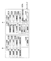
まず画像形成装置Aと製本装置Bの設定方法について説明する。図4〜図6は入力手段A4における表示画面の詳細図である。 First, a setting method for the image forming apparatus A and the bookbinding apparatus B will be described. 4 to 6 are detailed views of display screens in the input means A4.
図4は各種の表示及び操作を行う入力手段A4の基本画面を示す。冊子状原稿の読み取りを実行する場合は、まず応用機能釦K1を押す。応用機能釦K1が押されると図5に示すように応用機能に関する設定画面が表示される。設定画面上でページ連写釦K3を押すと、図6の設定画面が表示される。 FIG. 4 shows a basic screen of the input means A4 for performing various displays and operations. When reading a booklet original, the application function button K1 is first pressed. When the application function button K1 is pressed, a setting screen for application functions is displayed as shown in FIG. When the page continuous shooting button K3 is pressed on the setting screen, the setting screen of FIG. 6 is displayed.
図6は、画像読取手段A30の読み取り条件を設定する読取モード選択手段K30として機能する入力手段A4の設定画面である。同図に示す設定画面上でとじ方向、表紙の有無、表紙の読み取り方法は設定釦を押すことにより設定し、ページサイズ、背表紙幅の設定変更は各釦を押すことにより、機能設定の子画面がポップアップ(図示せず)するので、子画面で各種の釦を選択することにより行う。設定後にOK釦を押すことにより設定が完了する。 FIG. 6 is a setting screen of the input unit A4 functioning as the reading mode selection unit K30 for setting the reading conditions of the image reading unit A30. On the setting screen shown in the figure, the binding direction, presence / absence of cover page, and cover reading method are set by pressing the setting buttons, and the page size and spine cover width setting can be changed by pressing each button. Since the screen pops up (not shown), this is done by selecting various buttons on the sub-screen. The setting is completed by pressing the OK button after setting.
図7は、第一の実施形態に係る画像読取装置の動作を示すフローチャートである。まずステップS11では冊子状原稿の読み取りを実行するか否かを選択する。この選択は図5でページ連写K3釦を押すことにより行う。実行する場合(ステップS11のYes)には、続いて冊子状原稿の読み取り条件の設定を行う(ステップS12)。図6に示す例では左とじ釦K31と「表紙見開き読取/見開き読取」釦K35が選択されている状態を表している。次に背表紙幅とページサイズを入力する(ステップS13)。この入力は、図6においてページサイズ釦K36、背表紙幅釦K37の釦を押すことにより、表示される機能設定の子画面で行う。同図に示す例では表紙はB5判(縦257mm、横182mm)で、背表紙幅は5mmが入力されている状態を示している。なお定形(A4判、B5判等)の用紙サイズ情報は、あらかじめ不揮発メモリ103Aに記憶されている情報を呼び出すことにより取得できる。
FIG. 7 is a flowchart showing the operation of the image reading apparatus according to the first embodiment. First, in step S11, it is selected whether or not to read a booklet document. This selection is performed by pressing the page continuous shooting K3 button in FIG. If it is to be executed (Yes in step S11), then the reading conditions for the booklet document are set (step S12). In the example shown in FIG. 6, the left binding button K31 and the “cover spread reading / spreading” button K35 are selected. Next, the spine cover width and page size are input (step S13). This input is performed on the function setting sub-screen displayed by pressing the page size button K36 and the spine width button K37 in FIG. In the example shown in the figure, the cover is B5 size (length 257 mm, width 182 mm), and the spine cover width is 5 mm. Note that the standard size (A4 size, B5 size, etc.) paper size information can be acquired by calling information stored in advance in the
ステップS14では冊子状原稿BFの読み取りを実行する。表紙の読み取りは冊子状原稿BFを仰向けに原稿台A31に載置してから、ユーザが図4の原稿読込釦K2を押すことにより実行される。次に選択された読み取りモードで、読取制御手段がどのように制御するかについて説明する。以下の制御は、例えばROM101Aに記憶されたプログラムに基づきCPU100Aが実行する。
In step S14, the booklet document BF is read. The cover is read when the user presses the document reading button K2 of FIG. 4 after placing the booklet document BF on the document table A31 on its back. Next, how the reading control unit performs control in the selected reading mode will be described. The following control is executed by the
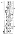
図8は、冊子状原稿と、読み取った画像データの対応関係を表す図である。図8(a)は冊子状原稿、図8(b)は読み取った画像データ、図8(c)、(d)は図8(b)の画像データを表紙用紙S2の表紙用紙領域に配置した状態を示す図である。 FIG. 8 is a diagram illustrating a correspondence relationship between a booklet-shaped document and read image data. 8A is a booklet document, FIG. 8B is the read image data, and FIGS. 8C and 8D are the image data of FIG. 8B arranged in the cover sheet area of the cover sheet S2. It is a figure which shows a state.
図8(a)において、BFは冊子状原稿で、各サイズは、オモテ表紙F、ウラ表紙Bの幅方向のページサイズは縦l、横wで、背表紙Sの幅はbである。BLは読み取りスキャンの基準となる基準線で、Scan矢印はスキャン方向を示す。前述の図6に示す入力例(K36、K37)では、lは257mm、wは182mm、bは5mmとなる。 In FIG. 8A, BF is a booklet-like document, and the sizes of the front cover F and the back cover B in the width direction are vertical l and horizontal w, and the width of the spine S is b. BL is a reference line serving as a reference for reading scan, and a Scan arrow indicates a scanning direction. In the input example (K36, K37) shown in FIG. 6, l is 257 mm, w is 182 mm, and b is 5 mm.
図8(b)は図6のK35釦により選択した表紙見開き読み取りモードで、冊子状原稿BFを読み取った画像データである。表紙見開き読取モードでは、入力手段から入力された背表紙Sの幅b、とページサイズの情報に基づき、見開きで仰向け状態の冊子状原稿BFをオモテ表紙F、背表紙S、ウラ表紙Bの画像データとして読み取りを行う。 FIG. 8B shows image data obtained by reading a booklet document BF in the cover spread reading mode selected by the K35 button in FIG. In the cover spread reading mode, a booklet document BF that is in a facing-up and lying state is displayed on the front cover F, the back cover S, and the back cover B based on the width b of the back cover S and the page size information input from the input unit. Read as data.
図8(a)に示す例では、スキャン方向上流側のスキャン基準線BL(0mm)からw(182mm)までの範囲をオモテ表紙Fの画像データとし、続くwからw+b(187mm)までの範囲を背表紙Sの画像データとし、次のw+bから2w+b(369mm)までの範囲をウラ表紙Bの画像データとして読み取りを行う。 In the example shown in FIG. 8A, the range from the scanning reference line BL (0 mm) to w (182 mm) on the upstream side in the scanning direction is the image data of the front cover F, and the subsequent range from w to w + b (187 mm). The image data of the back cover S is read, and the next range from w + b to 2w + b (369 mm) is read as the image data of the back cover B.
図7に戻ってフローの説明を続ける。続くステップS15で、読み取った画像データは表紙の表裏情報と関連づけられて記憶手段としての画像メモリ106Aに記憶される。 Returning to FIG. 7, the description of the flow will be continued. In the subsequent step S15, the read image data is stored in the image memory 106A as storage means in association with the front and back information of the cover.
なお、一実施態様として、背表紙幅bとページサイズ幅wの情報に基づき冊子状原稿の読み取りを行う例について説明したが、原稿サイズ検知手段107Aにより検出された見開き状態の原稿サイズ(2w+b)と入力手段A4から入力されたページサイズ幅wの情報に基づき、見開きで仰向け状態の冊子状原稿BFを、オモテ表紙F、背表紙S、ウラ表紙Bの画像データとして読み取りを行うようにしてもよい。このようにすることで、背表紙幅bの入力作業を省略することができる。
Note that, as an embodiment, an example in which a booklet document is read based on the information about the spine width b and the page size width w has been described. However, the document size (2w + b) in the spread state detected by the document
また原稿サイズ検知手段107Aとしては、予備スキャン方式ではなく、原稿台A31の下方に複数の光学センサを設け、その信号により原稿サイズを検知する方式を用いてもよい。 Further, as the document size detecting means 107A, instead of the preliminary scanning method, a method in which a plurality of optical sensors are provided below the document table A31 and the document size is detected based on the signal may be used.
このように表紙見開き読取モードが選択されると、入力手段から入力された冊子状原稿の背表紙幅及びページサイズの情報に基づき見開きの冊子状原稿をオモテ表紙、背表紙、ウラ表紙の画像データとして読み取りを行うように制御する読取制御手段とを有する画像読み取り装置とすることにより、冊子状原稿の表紙の読み取りを、背表紙を含めて適正に行うことが可能となる。 When the cover spread reading mode is selected in this way, the image data of the front cover, the back cover, and the back cover of the spread booklet document is input based on the information on the spine width and page size of the booklet document input from the input unit. By using the image reading apparatus having the reading control unit that controls to read the image, it is possible to appropriately read the cover of the booklet document including the spine.
図9は、第二の実施形態に係る画像形成システムの動作を示すフローチャートである。同図に示す実施形態では図7の実施形態に示す画像読み取り装置で読み取った画像データに基づいて表紙用紙S2に画像形成を行う。以下、説明する。 FIG. 9 is a flowchart showing the operation of the image forming system according to the second embodiment. In the embodiment shown in the figure, an image is formed on the cover sheet S2 based on the image data read by the image reading apparatus shown in the embodiment of FIG. This will be described below.
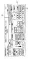
図9に示す動作フローは、ステップS11からS15は図7と共通するので説明を省略する。次に、ステップS20でくるみ製本出力の実行を行うか否かを選択する。くるみ製本出力を実行する場合には、図5に示すくるみ製本釦K4を押すことにより、図10のくるみ綴じの設定画面が表示される。設定画面上で表紙印刷の有無、表紙印刷面、表紙断裁の有無、とじ方向、背表紙幅、等を設定し、OK釦を押すと設定が完了する。 In the operation flow shown in FIG. 9, steps S11 to S15 are the same as those in FIG. In step S20, it is selected whether or not to execute case binding output. When the case binding output is executed, the case binding setting screen shown in FIG. 10 is displayed by pressing the case binding button K4 shown in FIG. On the setting screen, the presence / absence of front cover printing, front cover printing surface, front cover cutting presence / absence, binding direction, spine cover width, etc. are set and the OK button is pressed to complete the setting.
くるみ製本を実行する場合(ステップS20のYes)には、続くステップS21で、画像形成を行う表紙用紙領域のサイズ情報を取得する。以下、表紙用紙領域のサイズ情報の取得方法について説明する。なお以下の一連の手段が表紙用紙サイズ情報取得手段として機能する。 When case binding is executed (Yes in step S20), in step S21, the size information of the cover sheet area on which image formation is performed is acquired. Hereinafter, a method for acquiring the size information of the cover sheet area will be described. The following series of means function as cover sheet size information acquisition means.
表紙断裁が無い場合(釦K44で設定する)には、表紙用紙領域は、表紙用紙S2のサイズと一致する。この場合には、表紙用紙トレイ釦K42で選択された給紙トレイ(例えば7B)にあらかじめ関連づけられている表紙用紙S2のサイズ情報を呼び出し、その情報を表紙用紙領域として用いる。表紙用紙サイズ情報は各給紙トレイに備え付けられている用紙サイズ検知手段により検知されて給紙トレイと関連づけられて不揮発メモリ103Aに記憶されている。
When there is no cover cutting (set by the button K44), the cover sheet area matches the size of the cover sheet S2. In this case, the size information of the cover sheet S2 associated in advance with the paper feed tray (for example, 7B) selected by the cover sheet tray button K42 is called and the information is used as the cover sheet area. The cover sheet size information is detected by a sheet size detecting means provided in each sheet feed tray, and is associated with the sheet feed tray and stored in the
一方、表紙断裁がある場合(釦K44で設定する)には、表紙用紙領域のサイズを別途、取得する必要がある。この場合には、図10の表紙サイズ釦K43を押すことにより設定の子画面がポップアップする(図示せず)ので、用紙サイズを選択する、あるいはサイズを直接数値入力することにより表紙サイズを設定する。この設定された表紙サイズを表紙用紙領域として用いる。図10に示す例では、「B4ノビ」サイズが設定されており、あらかじめ本設定と関連づけられたサイズ情報を不揮発メモリ103Aから呼び出す。
On the other hand, when there is cover cutting (set by the button K44), it is necessary to separately acquire the size of the cover sheet area. In this case, a sub-setting screen pops up (not shown) when the cover size button K43 in FIG. 10 is pressed, so the cover size is set by selecting the paper size or by directly inputting the numerical value. . The set cover size is used as a cover sheet area. In the example illustrated in FIG. 10, the “B4 Nobi” size is set, and size information associated with this setting in advance is called from the
続いてステップS22では配置手段による表紙画像データの合成(配置)を行う。この手段は、例えばROM101Aに記憶されたプログラムをCPU100Aが実行することにより配置手段として機能する。以下、表紙画像データの配置について図8(c)、(d)に基づいて説明する。
In step S22, the cover image data is synthesized (arranged) by the arrangement means. For example, this means functions as an arrangement means when the
図8(c)は、表紙用紙S2のサイズが、表紙用紙領域と一致している場合の配置例である。同図において表紙用紙S2に図8(b)のオモテ表紙F、背表紙S、ウラ表紙Bの画像データを配置した状態を示した図である。E1、E2は表紙用紙S2の端部であり、cは表紙用紙S2の幅方向の中央位置(中心線)、Lは表紙用紙領域の長さ、tは表紙用紙S2における背表紙の領域(背表紙領域)の範囲である。 FIG. 8C shows an arrangement example when the size of the cover sheet S2 matches the cover sheet area. FIG. 9 is a diagram showing a state in which the image data of the front cover F, the back cover S, and the back cover B of FIG. 8B are arranged on the cover sheet S2. E1 and E2 are the end portions of the cover sheet S2, c is the center position (center line) in the width direction of the cover sheet S2, L is the length of the cover sheet area, and t is the area of the back cover (back) in the cover sheet S2. Cover area).
オモテ表紙Fの画像データは、表紙用紙領域(表紙用紙S2)の一方の端部E1を基準として順方向から配置し、ウラ表紙Bの画像データを表紙用紙領域(表紙用紙S2)の他方の端部E2を基準として逆方向から配置し、背表紙Sの画像データを同画像データの幅方向中央位置と表紙用紙領域(表紙用紙S2)の幅方向中央位置cが一致するように配置する。配置した画像データは1ページ分の画像データとして合成(マージ)して、画像メモリ106Aに記憶される。 The image data of the front cover F is arranged from the forward direction with one end E1 of the cover paper area (cover paper S2) as a reference, and the image data of the back cover B is the other end of the cover paper area (cover paper S2). The image data of the spine cover S is arranged from the reverse direction with reference to the portion E2, and the center position in the width direction of the image data and the center position c in the width direction of the cover sheet region (cover sheet S2) are aligned. The arranged image data is combined (merged) as image data for one page and stored in the image memory 106A.
図8(d)は、表紙用紙S2のサイズが表紙用紙領域と一致していない場合の配置例である。表紙用紙領域の長さLに対して表紙用紙S2は、Ld分だけ長くなっている。EXは余分領域であり、その領域には画像データの配置は行わない。 FIG. 8D shows an arrangement example when the size of the cover sheet S2 does not match the cover sheet area. The cover sheet S2 is longer than the length L of the cover sheet area by Ld. EX is an extra area, and no image data is arranged in that area.
同図においてオモテ表紙F、ウラ表紙B、背表紙Sの画像データは余分領域EXを除いた、表紙用紙領域にそれぞれ図8(c)と同様に配置する。なお表紙用紙S2の余分領域EXは、画像形成の後に後処理装置Bの断裁部70で切断を行う。E1は切断後の表紙用紙S2の端部である。
In the same figure, the image data of the front cover F, the back cover B, and the back cover S is arranged in the cover sheet area except for the extra area EX in the same manner as in FIG. The extra area EX of the cover sheet S2 is cut by the cutting
続くステップS23で画像形成手段A1により本身用紙S1、表紙用紙S2に画像形成を行う。なお表紙用紙S2には、ステップS22で合成した画像データに基づき画像形成が行われる。続くステップS24で本身用紙S1の束を表紙用紙S2でくるみ、くるみ製本処理によりくるみ本S3を形成する。 In subsequent step S23, the image forming unit A1 forms an image on the body sheet S1 and the cover sheet S2. Note that image formation is performed on the cover sheet S2 based on the image data synthesized in step S22. In subsequent step S24, a bundle of body sheets S1 is wrapped with cover sheet S2, and a case book S3 is formed by case binding processing.
なお、一実施態様として、表紙サイズ情報(表紙用紙領域)に基づき画像データを配置する例について説明をしたが、表紙サイズ情報の代わりに入力手段A4(図6のK37、K37)から入力された冊子状原稿の背表紙幅bとページサイズの幅wを用いて表紙サイズを決定(2w+b)するようにしてもよい。更に、その場合に表紙用紙S2が決定された表紙サイズ値よりも大きい場合には断裁部70で適正な長さになるよう断裁を行うようにしてもよい。
As an embodiment, the example in which the image data is arranged based on the cover size information (cover paper area) has been described. However, instead of the cover size information, the image data is input from the input unit A4 (K37 and K37 in FIG. 6). The cover size may be determined (2w + b) using the back cover width b and the page size width w of the booklet-like document. Further, in this case, when the cover sheet S2 is larger than the determined cover size value, the cutting
このようにオモテ表紙の画像データを表紙用紙S2の一方の端部を基準として配置し、ウラ表紙の画像データを他方の端部を基準として配置し、背表紙の画像データをその中央位置と表紙用紙S2の中央位置を一致させるように配置する配置手段とを有する画像形成システムとすることにより冊子状原稿の複写を行う場合に背表紙を含めて適正に読み取り、及び出力が可能な画像形成システムを得ることが可能となる。 In this way, the front cover image data is arranged with one end of the cover sheet S2 as a reference, the back cover image data is arranged with the other end as a reference, and the back cover image data is set to the center position and the cover. By forming an image forming system having an arrangement unit that arranges the paper S2 so that the center positions thereof coincide with each other, an image forming system capable of appropriately reading and outputting including a spine when copying a booklet document. Can be obtained.
図11は、第三の実施形態に係る画像形成システムの動作を示すフローチャートである。同図に示す例は、束厚取得手段として、束厚測定手段509を用いた例である。
FIG. 11 is a flowchart showing the operation of the image forming system according to the third embodiment. The example shown in the figure is an example in which a bundle
まず印刷JOBに基づき本身用紙S1に画像形成を行う(ステップS31)、続いて印刷JOBで設定された設定枚数までの本身用紙S1を集積部50に集積する(ステップS32)。集積した本身用紙S1の束の厚さtを束厚測定手段509により測定する(ステップS33)。続いてステップS34では、比較手段により画像メモリ106Aに記憶されている背表紙Sの画像幅bと、束厚取得手段により取得した本身用紙S1の束の厚さtとの比較を行う。この比較は、例えばROM101Bに記憶されたプログラムに基づきCPU100Bが実行する。
First, an image is formed on the body paper S1 based on the print job (step S31), and then up to the set number of body papers S1 set in the print job are stacked on the stacking unit 50 (step S32). The bundle thickness measuring means 509 measures the thickness t of the bundle of the accumulated body sheets S1 (step S33). In step S34, the comparison unit compares the image width b of the spine cover S stored in the image memory 106A with the bundle thickness t of the body sheets S1 acquired by the bundle thickness acquisition unit. This comparison is executed by the CPU 100B based on a program stored in the
背表紙Sの画像幅bが本身用紙S1の束の厚さtとが同じでないと判断されると(ステップS34のNo)背表紙画像データが表紙用紙S2の背表紙領域の範囲内に収まるように背表紙の画像サイズ変更のサブルーチン処理を行う(ステップS35)。以下、サブルーチン処理について図12のフローチャートに基づいて説明する。 If it is determined that the image width b of the spine cover S is not the same as the bundle thickness t of the main sheets S1 (No in step S34), the spine image data is within the range of the spine area of the cover sheet S2. Then, a subroutine process for changing the image size of the spine is performed (step S35). Hereinafter, the subroutine processing will be described based on the flowchart of FIG.
図12(a)では、まず背表紙Sの画像幅bと本身用紙S1の束の厚さt(表紙用紙S2での背表紙領域)とを比較する(ステップS351)。そしてbがtよりも大きいと判断された場合には(ステップS351のYes)背表紙Sの画像が、表紙用紙S2の背表紙領域の範囲内に収まるように背表紙の画像データのトリミングを行う(ステップS352a)。一方、bがtよりも大きくないと判断された場合には余白部分には白紙の画像データを追加する(ステップ353a)。以下、トリミング処理と、白紙データ追加処理について図に基づいて説明する。 In FIG. 12A, first, the image width b of the back cover S is compared with the thickness t of the bundle of the body sheets S1 (the back cover area on the cover sheet S2) (step S351). If it is determined that b is larger than t (Yes in step S351), the image data of the back cover is trimmed so that the image of the back cover S is within the range of the spine area of the cover paper S2. (Step S352a). On the other hand, if it is determined that b is not greater than t, blank image data is added to the margin (step 353a). Hereinafter, the trimming process and the blank data addition process will be described with reference to the drawings.
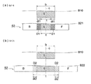
図13は、背表紙Sの画像データの幅方向サイズ変更を示す説明図である。B10は背表紙Sの画像データ、B21、B22は表紙用紙S2にオモテ表紙Fとウラ表紙Bと背表紙Sの画像データを配置したものである(図8(c)に対応)。 FIG. 13 is an explanatory diagram showing a change in the size of the image data of the spine cover S in the width direction. B10 is the image data of the back cover S, and B21 and B22 are the image data of the front cover F, the back cover B, and the back cover S arranged on the cover sheet S2 (corresponding to FIG. 8C).
図13(a)は背表紙Sの画像データに対するトリミング処理を示した説明図であり、b>tである場合には背表紙Sの画像データは表紙用紙の背表紙領域の範囲tに収まらないので、オモテ表紙あるいはウラ表紙の領域と背表紙の領域が重なってしまう。領域D1は両者の重なる領域である。 FIG. 13A is an explanatory diagram showing trimming processing for the image data of the spine cover S. When b> t, the image data of the spine cover S does not fit in the range t of the spine cover area of the cover sheet. Therefore, the area of the front cover or back cover overlaps the area of the spine cover. A region D1 is a region where both overlap.
配置手段により、背表紙画像が表紙用紙の背表紙領域の範囲内に収まるように、背表紙の画像データの重複する領域D1に対してトリミング処理を行う。同図に示す例(B21)では、背表紙Sの画像データに対して中央の画像を残すように、両端に対してそれぞれ同等のdt1の幅で削除を行っている。なおdt1とb、tとは、dt1=(b−t)/2の関係となる。 Trimming processing is performed on the overlapping region D1 of the image data of the spine so that the spine image fits within the range of the spine region of the cover sheet. In the example (B21) shown in the figure, the image data of the spine cover S is deleted with the same width of dt1 at both ends so as to leave the center image. Note that dt1, b, and t have a relationship of dt1 = (b−t) / 2.
図13(b)は余白部分に白紙の画像データを追加する処理を示した説明図である。b<tである場合には背表紙Sの画像データは表紙用紙の背表紙領域の範囲tよりも小さいので、オモテ表紙あるいはウラ表紙の領域と背表紙の領域の間に空白(隙間)領域ができてしまう。領域D2は空白領域である。 FIG. 13B is an explanatory diagram showing processing for adding blank image data to the margin. When b <t, the image data of the spine cover S is smaller than the range t of the spine cover area of the cover paper, so there is a blank (gap) area between the front cover page or the back cover area and the spine cover area. I can do it. Area D2 is a blank area.
配置手段により背表紙画像が、表紙用紙のオモテ表紙領域とウラ表紙領域に挟まれた領域、に隙間なく収まるように、背表紙の画像データに対して空白領域D2分の白紙画像データを追加する。同図に示す例(B22)では、背表紙Sの画像データと、表紙用紙S2の中央を一致させるように配置させているので背表紙Sの画像データの両脇にそれぞれ同等のdt2幅の白紙画像データを追加している。なおdt2=(t−b)/2となる。 Blank image data for the blank area D2 is added to the image data of the spine so that the spine image fits in the area between the front cover area and the back cover area of the cover sheet with no gap by the arranging means. . In the example (B22) shown in the figure, since the image data of the spine cover S and the center of the cover paper S2 are arranged so as to coincide with each other, the blank paper having the same dt2 width is provided on both sides of the image data of the spine cover S. Image data has been added. Note that dt2 = (t−b) / 2.
図12(b)は背表紙Sの画像サイズ変更のサブルーチン処理の変形例を示すフローチャートである。同図に示す実施形態では背表紙画像データの幅方向を、t/b倍に縮小や拡大の倍率変更を行う(ステップ352b)。例えば背表紙Sの画像幅bが10mmで、表紙用紙S2での背表紙の領域tが8mmの場合には、背表紙Sの画像幅bはt/b=0.8倍の8mmに縮小するように倍率変更を行う。なおこの際、背表紙Sの画像データの縦方向の長さlは変更する必要はない。 FIG. 12B is a flowchart showing a modification of the subroutine processing for changing the image size of the spine cover S. In the embodiment shown in the figure, the width direction of the spine image data is reduced to t / b times and the magnification is changed (step 352b). For example, when the image width b of the spine cover S is 10 mm and the area t of the spine cover S2 is 8 mm, the image width b of the spine cover S is reduced to 8 mm, which is t / b = 0.8 times. Change the magnification as follows. At this time, it is not necessary to change the longitudinal length l of the image data of the spine cover S.
図11に戻って動作フローの説明を続ける。背表紙の画像サイズ変更のサブルーチン処理により、背表紙Sの画像幅bが本身用紙S1の束の厚さ(表紙用紙S2での背表紙の領域)tとが同じになると、あるいはステップS34で両者が同一幅であると判断された場合には、続くステップS22で配置手段による表紙画像データの合成(配置)を行う。次のステップS36で画像形成手段A1により表紙用紙S2に画像形成を行う。なおこの画像形成は、ステップS22で合成した画像データに基づき画像形成が行われる。続くステップS24で本身用紙S1の束を表紙用紙S2でくるみ、くるみ製本処理により冊子を形成する。 Returning to FIG. 11, the description of the operation flow will be continued. As a result of the subroutine processing for changing the image size of the spine cover, when the image width b of the spine cover S becomes equal to the thickness of the bundle of body paper S1 (the area of the spine cover on the cover paper S2), or both in step S34. Are determined to have the same width, cover image data is synthesized (arranged) by the arrangement means in the subsequent step S22. In the next step S36, the image forming unit A1 forms an image on the cover sheet S2. This image formation is performed based on the image data synthesized in step S22. In subsequent step S24, a bundle of body sheets S1 is wrapped with cover sheet S2, and a booklet is formed by the case binding process.
なお、上記に示す例では、束厚取得手段として、束厚測定手段509を用いる例について説明を行ったが、これに限られず、入力手段A4を束厚取得手段として用い、ユーザからの入力値を本身用紙S1の束厚情報としてもよい。例えば、図10において出力背表紙幅釦K41を押すことにより背表紙幅(本身用紙S1の束の厚さ)tを入力することができる。
In the above example, the example in which the bundle
更に、別の例として入力手段A4から本身用紙の1枚あたりの厚さを入力し、出力する本身用紙の束の枚数とを乗じた値を、本身用紙の束の厚さtとして用いてもよい。図10は入力手段4を束厚取得手段として用いた例である。同図において本身用紙紙種/厚さ釦K51を押すことにより、機能設定の子画面がポップアップ(図示せず)するので、子画面で数値入力することにより本身用紙の1枚あたりの厚さを入力することができる。設定後にOK釦を押すことにより設定が完了する。同図に示す例では本身用紙の1枚あたりの厚さは0.10mmが入力されている。例えば、本身用紙の束の枚数が100枚の場合には、本身用紙の束の厚さtは両者を乗じた値、つまり10.00mmとなる。また、あらかじめ用紙の斤量と厚さとの換算テーブルを記憶手段に記憶しておき、使用する本身用紙の斤量を入力することにより、本身用紙の1枚あたりの厚さを求めるようにしてもよい。
Further, as another example, a value obtained by inputting the thickness of one body sheet from the input unit A4 and multiplying it by the number of body sheet bundles to be output may be used as the thickness t of the body sheet bundle. Good. FIG. 10 shows an example in which the
このように、束厚取得手段により取得した本身用紙S1の束の厚さtと記憶手段としての画像メモリ106Aに記憶された背表紙Sの画像幅bとを比較する比較手段とを有し、比較手段の比較結果に応じて背表紙画像が表紙用紙S2の背表紙の領域範囲内に収まるように背表紙Sの画像幅bの変更を行う画像形成システムとすることにより、読み取りを行う冊子と出力の冊子において、背表紙の厚さ(背表紙幅)が異なる場合であっても、冊子状原稿の背表紙画像を出力する冊子の背表紙に適正に配置することが可能な画像形成システムを得ることが可能となる。 In this way, it has a comparing means for comparing the thickness t of the bundle of the body sheets S1 acquired by the bundle thickness acquiring means with the image width b of the spine cover S stored in the image memory 106A as the storing means. By using an image forming system that changes the image width b of the spine cover S so that the spine cover image falls within the area of the spine cover of the cover sheet S2 in accordance with the comparison result of the comparison means, An image forming system capable of appropriately arranging on a back cover of a booklet for outputting a back cover image of a booklet-like document even when the thickness of the back cover (back cover width) is different in the output booklet. Can be obtained.
更に幅方向の倍率をt/b倍とすることにより、画像データのトリミングによる文字欠けや、空白データ追加に伴う背表紙画像データとの不自然な境界が生じる、等の問題が発生することなく、背表紙に適正に画像を配置することが可能となる。 Furthermore, by setting the magnification in the width direction to t / b times, problems such as missing characters due to trimming of image data and unnatural boundaries with spine image data due to the addition of blank data do not occur. The image can be properly arranged on the spine.
A 画像形成装置
B 製本装置(製本手段)
A1 画像形成手段
A4 入力手段
A30 画像読取手段
A31 原稿台
100A、100B CPU
101A、101B ROM
106A 画像メモリ
50 集積部
509 束厚測定手段
S1 本身用紙
S2 表紙用紙
A Image forming apparatus B Bookbinding device (bookbinding means)
A1 Image forming means A4 Input means A30 Image reading means A31 Document table 100A, 100B CPU
101A, 101B ROM
Claims (6)
冊子状原稿を読み取り可能な画像読取手段と、
読み取った画像データを記憶する記憶手段と、
見開きの冊子状原稿の読み取りモードを選択する読取モード選択手段と、
前記読取モード選択手段で、表紙見開き読取モードが選択されると、前記入力手段から入力された冊子状原稿の背表紙幅及びページサイズ、の情報に基づき見開きの冊子状原稿をオモテ表紙、背表紙、ウラ表紙の画像データとして読み取りを行うように制御する読取制御手段と、
本身用紙及び表紙用紙に画像データに基づいて画像形成を行う画像形成手段と、
画像形成される本身用紙の束の厚さ情報を取得する束厚取得手段と、を有する画像形成システムであって、
前記束厚取得手段により取得した本身用紙の束の厚さ情報と前記記憶手段に記憶された背表紙の画像幅の情報とを比較する比較手段と、
前記比較手段による比較の結果、背表紙の画像幅が本身用紙の束の厚さよりも大きいと判断されると、表紙用紙の背表紙領域の範囲内に背表紙の画像が収まるように背表紙の画像データのトリミングを行い、背表紙の画像幅が本身用紙の束の厚さよりも小さいと判断されると、表紙用紙の背表紙領域の余白部分に白紙画像データを追加して、オモテ表紙の画像データとウラ表紙の画像データと合成して表紙画像データの配置を行う配置手段とを有し、
前記配置手段で配置された表紙画像データに基づき、表紙用紙に前記画像形成手段で画像形成することを特徴とする画像形成システム。 Input means for making various inputs;
Image reading means capable of reading a booklet document;
Storage means for storing the read image data;
A reading mode selection means for selecting a reading mode of a booklet document with a spread;
When the cover-page spread reading mode is selected by the reading mode selection means, the spread booklet original is read as a front cover and a back cover based on the information on the spine width and page size of the booklet original input from the input means. Reading control means for controlling reading as image data of the back cover;
Image forming means for forming an image on the body paper and the cover paper based on the image data;
An image forming system comprising: a bundle thickness acquisition unit that acquires thickness information of a bundle of body sheets to be imaged;
A comparison unit that compares the thickness information of the bundle of body sheets acquired by the bundle thickness acquisition unit with the information on the image width of the spine cover stored in the storage unit;
As a result of the comparison by the comparison means, if it is determined that the image width of the spine is larger than the thickness of the stack of body paper, If the image data is trimmed and the image width of the spine cover is determined to be smaller than the thickness of the bundle of body paper, blank image data is added to the margin of the spine cover area of the cover paper, and the front cover image An arrangement means for arranging the cover image data by combining the data and the image data of the back cover,
An image forming system, wherein the image forming unit forms an image on a cover sheet based on the cover image data arranged by the arranging unit.
冊子状原稿を読み取り可能な画像読取手段と、
原稿のサイズを検知する原稿サイズ検知手段と、
読み取った画像データを記憶する記憶手段と、
見開きの冊子状原稿の読み取りモードを選択する読取モード選択手段と、
前記読取モード選択手段で、表紙見開き読取モードが選択されると、前記原稿サイズ検知手段により検知された原稿サイズ情報と前記入力手段から入力された冊子状原稿のページサイズ、の情報に基づき見開きの冊子状原稿をオモテ表紙、背表紙、ウラ表紙の画像データとして読み取りを行うように制御する読取制御手段と、
本身用紙及び表紙用紙に画像データに基づいて画像形成を行う画像形成手段と、
画像形成される本身用紙の束の厚さ情報を取得する束厚取得手段と、を有する画像形成システムであって、
前記束厚取得手段により取得した本身用紙の束の厚さ情報と前記記憶手段に記憶された背表紙の画像幅の情報とを比較する比較手段と、
前記比較手段による比較の結果、背表紙の画像幅が本身用紙の束の厚さよりも大きいと判断されると、表紙用紙の背表紙領域の範囲内に背表紙の画像が収まるように背表紙の画像データのトリミングを行い、背表紙の画像幅が本身用紙の束の厚さよりも小さいと判断されると、表紙用紙の背表紙領域の余白部分に白紙画像データを追加して、オモテ表紙の画像データとウラ表紙の画像データと合成して表紙画像データの配置を行う配置手段とを有し、
前記配置手段で配置された表紙画像データに基づき、表紙用紙に前記画像形成手段で画像形成することを特徴とする画像形成システム。 Input means for making various inputs;
Image reading means capable of reading a booklet document;
A document size detecting means for detecting the size of the document;
Storage means for storing the read image data;
A reading mode selection means for selecting a reading mode of a booklet document with a spread;
In the reading mode selecting means, cover the spread reading mode is selected, spread on the basis of the document size page size of the booklet-like document that is input from the detection knowledge original size information input means by detecting means, the information Reading control means for controlling to read the booklet original as image data of the front cover, the back cover, and the back cover,
Image forming means for forming an image on the body paper and the cover paper based on the image data;
An image forming system comprising: a bundle thickness acquisition unit that acquires thickness information of a bundle of body sheets to be imaged;
A comparison unit that compares the thickness information of the bundle of body sheets acquired by the bundle thickness acquisition unit with the information on the image width of the spine cover stored in the storage unit;
As a result of the comparison by the comparison means, if it is determined that the image width of the spine is larger than the thickness of the stack of body paper, If the image data is trimmed and the image width of the spine cover is determined to be smaller than the thickness of the bundle of body paper, blank image data is added to the margin of the spine cover area of the cover paper, and the front cover image An arrangement means for arranging the cover image data by combining the data and the image data of the back cover,
An image forming system, wherein the image forming unit forms an image on a cover sheet based on the cover image data arranged by the arranging unit.
前記配置手段が、前記表紙用紙サイズ情報取得手段から取得した表紙用紙サイズ情報に基づき、オモテ表紙の画像データを表紙用紙領域の一方の端部を基準として配置し、ウラ表紙の画像データを他方の端部を基準として配置し、背表紙の画像データを表紙用紙領域の中央位置に配置することを特徴とする請求項1又は2に記載の画像形成システム。 Cover page size information acquisition means for acquiring cover page size information is provided,
Based on the cover sheet size information acquired from the cover sheet size information acquisition unit , the arrangement unit arranges the image data of the front cover on the basis of one end of the cover sheet region, and the image data of the back cover is set on the other side. the end is disposed as a reference, an image forming system according to claim 1 or 2, characterized in the Turkey to place the image data of the spine to the center of the cover sheet region.
Priority Applications (1)
| Application Number | Priority Date | Filing Date | Title |
|---|---|---|---|
| JP2006222246A JP4259552B2 (en) | 2006-08-17 | 2006-08-17 | Image forming system |
Applications Claiming Priority (1)
| Application Number | Priority Date | Filing Date | Title |
|---|---|---|---|
| JP2006222246A JP4259552B2 (en) | 2006-08-17 | 2006-08-17 | Image forming system |
Publications (2)
| Publication Number | Publication Date |
|---|---|
| JP2008048185A JP2008048185A (en) | 2008-02-28 |
| JP4259552B2 true JP4259552B2 (en) | 2009-04-30 |
Family
ID=39181492
Family Applications (1)
| Application Number | Title | Priority Date | Filing Date |
|---|---|---|---|
| JP2006222246A Expired - Fee Related JP4259552B2 (en) | 2006-08-17 | 2006-08-17 | Image forming system |
Country Status (1)
| Country | Link |
|---|---|
| JP (1) | JP4259552B2 (en) |
Families Citing this family (4)
| Publication number | Priority date | Publication date | Assignee | Title |
|---|---|---|---|---|
| JPS6179850A (en) * | 1984-09-25 | 1986-04-23 | Mitsubishi Electric Corp | Stirling engine |
| JP4502045B2 (en) * | 2008-06-10 | 2010-07-14 | コニカミノルタビジネステクノロジーズ株式会社 | Control device, spine width calculation system, spine width calculation method, and spine width calculation program |
| JP6123486B2 (en) * | 2013-05-28 | 2017-05-10 | ブラザー工業株式会社 | Image information processing apparatus and program |
| CN115147253A (en) * | 2022-09-01 | 2022-10-04 | 北京吉道尔科技有限公司 | Block chain-based smart campus book big data borrowing management method and system |
-
2006
- 2006-08-17 JP JP2006222246A patent/JP4259552B2/en not_active Expired - Fee Related
Also Published As
| Publication number | Publication date |
|---|---|
| JP2008048185A (en) | 2008-02-28 |
Similar Documents
| Publication | Publication Date | Title |
|---|---|---|
| JP5252844B2 (en) | PRINT CONTROL DEVICE, CONTROL METHOD FOR PRINT CONTROL DEVICE, AND PROGRAM | |
| US11528373B2 (en) | Printing apparatus and control method for determining a print order of images on sheets based on a binding setting | |
| US8049920B2 (en) | Image forming system and book binding apparatus | |
| JP5328337B2 (en) | Image forming apparatus, image forming system, control method for image forming apparatus, and program | |
| JP6071462B2 (en) | Print control apparatus, print control method, and program | |
| CN100461016C (en) | image forming device | |
| JP4259552B2 (en) | Image forming system | |
| US8170464B2 (en) | Image forming apparatus capable of preventing mismatching of punched hole position and binding direction | |
| JP7293967B2 (en) | Report creation device and report creation method | |
| JP4733528B2 (en) | Image forming apparatus, image forming system, and control program | |
| US20070017397A1 (en) | Image printing system, image printing method, and image printing program | |
| US6516170B2 (en) | Image forming apparatus which enables easy to observe printing in a manner adaptable to a user's request | |
| US7603074B2 (en) | Image forming system, image forming device and bookbinding device | |
| JP2010052919A (en) | Sheet processing device and image forming device | |
| JP2008012749A (en) | Image forming system, image forming device and control program | |
| JP2008068471A (en) | Image forming system and method for controlling the same | |
| JP6177344B2 (en) | Image processing apparatus and image processing method | |
| JP4369414B2 (en) | Image forming apparatus and saddle stitch control program | |
| JP5615413B2 (en) | Image forming apparatus, image forming system, control method for image forming apparatus, and program | |
| JP2025019884A (en) | Printer driver, information processing device, and control method thereof | |
| JP5546652B2 (en) | Image forming system and image forming apparatus | |
| JP5446431B2 (en) | Image forming apparatus | |
| JP2007150812A (en) | Image forming apparatus and bookbinding system | |
| JP2006279256A (en) | Image editing apparatus, image forming system, and image forming program | |
| JP2005266127A (en) | Image forming apparatus and control device to be used therefor |
Legal Events
| Date | Code | Title | Description |
|---|---|---|---|
| A977 | Report on retrieval |
Free format text: JAPANESE INTERMEDIATE CODE: A971007 Effective date: 20080715 |
|
| A131 | Notification of reasons for refusal |
Free format text: JAPANESE INTERMEDIATE CODE: A131 Effective date: 20080722 |
|
| A521 | Written amendment |
Free format text: JAPANESE INTERMEDIATE CODE: A523 Effective date: 20080922 |
|
| TRDD | Decision of grant or rejection written | ||
| A01 | Written decision to grant a patent or to grant a registration (utility model) |
Free format text: JAPANESE INTERMEDIATE CODE: A01 Effective date: 20090120 |
|
| A01 | Written decision to grant a patent or to grant a registration (utility model) |
Free format text: JAPANESE INTERMEDIATE CODE: A01 |
|
| A61 | First payment of annual fees (during grant procedure) |
Free format text: JAPANESE INTERMEDIATE CODE: A61 Effective date: 20090202 |
|
| FPAY | Renewal fee payment (event date is renewal date of database) |
Free format text: PAYMENT UNTIL: 20120220 Year of fee payment: 3 |
|
| R150 | Certificate of patent or registration of utility model |
Free format text: JAPANESE INTERMEDIATE CODE: R150 |
|
| LAPS | Cancellation because of no payment of annual fees |