JP4258909B2 - Vehicle alternator - Google Patents
Vehicle alternator Download PDFInfo
- Publication number
- JP4258909B2 JP4258909B2 JP26318199A JP26318199A JP4258909B2 JP 4258909 B2 JP4258909 B2 JP 4258909B2 JP 26318199 A JP26318199 A JP 26318199A JP 26318199 A JP26318199 A JP 26318199A JP 4258909 B2 JP4258909 B2 JP 4258909B2
- Authority
- JP
- Japan
- Prior art keywords
- vehicle
- fin
- diode
- pulley
- winding
- Prior art date
- Legal status (The legal status is an assumption and is not a legal conclusion. Google has not performed a legal analysis and makes no representation as to the accuracy of the status listed.)
- Expired - Fee Related
Links
Images


Landscapes
- Motor Or Generator Cooling System (AREA)
- Synchronous Machinery (AREA)
Description
【0001】
【発明の属する技術分野】
本発明は車両用交流発電機に係り、特にその冷却技術に関する。
【0002】
【従来の技術】
従来の車両用交流発電機の冷却技術としては、特開昭62−217837号公報に記載のものがある。
【0003】
この公報には、整流器の冷却方法として整流器の片面を水路に接するように配置することが開示されている。
【0004】
また界磁巻線の冷却方法として、界磁巻線が回転しないブラシレス構造のものを対象に、界磁巻線を直接良熱伝導体に接触させ該良熱伝導体を通じて水路に熱を逃がすことが開示されている。
【0005】
【発明が解決しようとする課題】
上記従来技術は整流器をその片面から冷却する構成であるため、ダイオードと固定子コイルを接続するためのターミナル及びダイオードのリード部分での発熱を冷却することは困難であった。従って、ダイオード自体は冷却できてもそれら接続部(ターミナル,リード)で発生するジュール熱を冷却することができないという問題点があった。
【0006】
また、上記従来技術は水路を構成する冷却カバーと整流器が独立して構成されているため、整流器から冷却カバーを介して熱が伝わるときに熱抵抗が大きく、冷却効率が悪いという課題があった。
【0007】
本発明が解決しようとする第1の課題は、整流素子であるダイオード,接続部に用いられるターミナル及びダイオードのリード部分で発生するジュール熱を効率良く冷却することである。
【0008】
本発明が解決しようとする第2の課題は、上記公報のような界磁巻線が回転しないブラシレス構造の交流発電機ではなく、界磁巻線が回転する交流発電機において、界磁巻線のジュール熱を効率良く冷却することである。
【0009】
【課題を解決するための手段】
本発明は、界磁巻線と、複数の磁極と、一方の端部にプーリを有するシャフトとを有する回転子と、界磁巻線により複数の磁極を磁化することによって固定子巻線に交流電圧を発生する固定子と、固定子を固定するハウジングと、ハウジングの反プーリ側に設けられ、ハウジングに形成された凹部をリアプレートによって蓋することによって形成された水路と、リアプレートの前記水路とは反対側の面に配置され、固定子巻線に発生した交流電圧を整流する複数の整流素子と、複数の整流素子を覆うように、ハウジングの反プーリ側に固定されたリアブラケットと、複数の整流素子をモールドし、整流素子とリアブラケットとの間に設けられた熱伝導体と、を有する車両用交流発電機である。
【0010】
また、本発明は、固定子及び回転子の軸方向両側を覆う2つのブラケットのうち、少なくとも1つのブラケットに、固定子の巻線とほぼ同じ外径の開口部を設けたことを特徴とする。
【0013】
【発明の実施の形態】
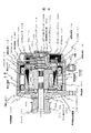
図1は本発明の一実施形態をなす車両用交流発電機の縦断面図である。
【0014】
車両用交流発電機1は2個のブラケットを備え、このブラケットはプーリ102側に配置されるフロントブラケット103及び反プーリ側リアブラケット104からなる。
【0015】
両ブラケットの中心部にはシャフト101がプーリ側ベアリング100F,反プーリ側ベアリング100Rを介して支持され、シャフト101の一方の端部にはプーリ102が取り付けられ、もう一方の端部にはスリップリング110が取り付けられている。
【0016】
先に述べた、プーリ側ベアリング100Fはベアリングの外輪の回り止めとしてベアリングリテーナ120がフロントブラケット103に設けられている。
【0017】
プーリ102はベルトを介してエンジンの出力軸に配置されたプーリと接続され、エンジンの回転数に比例して回転する。
【0018】
スリップリング110にはブラシ111が摺動可能に取り付けられ、ブラシ111から後述する界磁巻線107に界磁巻線口出し線107aを介して電力を供給する。
【0019】
また、シャフト101の中央部には回転子(ロータ)が取り付けられている。回転子コア300の外周部には爪形の形状を持つ一対の爪形磁極部108が配置されている。
【0020】
また、回転子の中心部には界磁巻線107が巻かれ、この界磁巻線107にスリップリング110からの直流電流を流すことによって前記爪形磁極部108を磁化させる。
【0021】
一対の爪形磁極部108の間には永久磁石118が配置され、残りの空間部分から界磁巻線107の空間部には良熱伝導体116が配置され、回転子の爪形磁極部108の最外周部には良熱伝導体116の飛び出しを防止するための飛散防止カバー117が配置されている。
【0022】
プーリ側フロントブラケット103と反プーリ側リアブラケット104の間には固定子コア105が内蔵されたハウジング115が配置され、この固定子コア105の内周面は回転子の爪形磁極部108表面に配置される飛散防止カバー117と僅かな間隔(機械的ギャップ)を隔てて配置されている。
【0023】
この機械的ギャップ長は機械的特性の関係から必要となる予め決められた間隔であり、一般的には0.4〜0.6mm程度である。固定子コア105にはティースとスロットが配置され、この固定子コア105の凹部に相当するスロットには固定子巻線106が3相に巻かれており、エンジンの駆動によって爪形磁極部108が回転して磁化されると、固定子巻線106に3相の誘起電圧が発生する。
【0024】
固定子コア105はハウジング115の内側にヤキバメにより固定されるが、固定子コア105のスロット内の固定子巻線106の隙間およびコイルエンドには、良熱伝導体116が充填され、結果的には固定子コア105と固定子巻線106とハウジング115は良熱伝導体116で一体的に成型されて熱的に接続されている。ここで述べた良熱伝導体は、例えば熱伝導率が1.0(W/mK)よりも大きいシリコンゴム系のものや熱伝導率の高いエポキシ樹脂等である。
【0025】
ハウジング115には冷却水が流れるための水路114が形成されている。また、ハウジング115の反プーリ側にはダイオードを冷却するための水路114も構成されている。このダイオードの冷却水路114を塞ぐためにリアプレート112が配置され、そのリアプレート112にダイオードモジュールが配置される。
【0026】
ハウジング115とリアプレート112の間には水漏れを防止するためのシール材(図示せず)が配置されている。そのリアプレート112はその外側に配置されるリアブラケット104によりハウジング115にネジを用いて固定されている。
【0027】
反プーリ側リアブラケット104の内側には、整流回路を構成するダイオードのモジュールであるダイオードのマイナスフィン109bの上に絶縁材を介してダイオードのプラスフィン109aが構成され、ダイオードのマイナスフィン109bは直接冷却水路114を密閉するためのリアプレート112に固定されている。
【0028】
また、発電電圧を調整するためのICレギュレータ113は前記リアブラケット104に冷却面が接するように配置されている。
【0029】
ダイオードのプラスフィン109aは、図示しないバッテリーのプラス電極に接続され、ダイオードのマイナスフィン109bは車両用交流発電機1の本体と同一電位となっていて、図示しないバッテリーのマイナス端子側に電気的に接続される。
【0030】
これらのダイオードは固定子巻線106で発生した3相交流電圧を全波整流し直流電圧に変換する。
【0031】
ICレギュレータ113は、バッテリーを充電するためにダイオードで整流した直流電圧が約14.3V 程度の一定電圧に保たれるよう、界磁巻線電流を制御する。
【0032】
また、ダイオードのマイナスフィン109b,ダイオードのプラスフィン109a,ダイオードと固定子巻線106の口出し線を接続するためのターミナル121は、良熱伝導体116により密封されリアブラケット104及びリアプレート112に熱的に接続され放熱が良好に行われると共に、防水の効果を持たせている。
【0033】
また、回転子コア300の軸方向端部をなす面200に対向する筐体部材のうち、フロントブラケット103に冷却促進部119F,ハウジング115の反プーリ側には冷却促進部119Rが配置されている。これら筐体部材と回転子コア300の軸方向端部をなす面200のギャップ長g1及びg2は0.3mm〜1.0mm程度のものである。
【0034】
以上のように構成した車両用交流発電機1において、エンジンの駆動によってプーリ102が回転すると、シャフト101はスリップリング110及び回転子と一緒に回転し、ブラシ111からの直流電流が回転子内部の界磁巻線107に通電され、界磁巻線107は爪形磁極部108のそれぞれの磁極にN極及びS極を構成するように動作する。
【0035】
この界磁巻線107による磁束は、N極の爪形磁極部の爪部から出たものが、固定子コア105を通りS極の爪形磁極部の爪部に戻る磁気回路を形成する。この磁気回路の磁束が固定子巻線106を差交することにより、固定子巻線106に3相の誘起電圧が発生する。
【0036】
この3相の誘起電圧は先のダイオードプラスフィン109aとマイナスフィン109b上に配置されたダイオード群により全波整流され直流電圧に変換される。整流された直流電圧は約14.3V 程度の一定電圧になるようにICレギュレータ113で界磁巻線電流を制御することで達成している。
【0037】
先に述べた爪磁極間に配置した永久磁石は爪磁極間に同極が向かい合う方向に着磁したもので固定子巻線を通る有効磁束を増加させるためのものである。
【0038】
本実施形態では冷却方式に水冷を採用しているために、低速で発電しても冷却効果が期待できることから、爪磁極間には耐熱性の高いネオジム磁石を採用している。
【0039】
次に固定子巻線106で発生する銅損による発熱の冷却について説明する。
【0040】
先にも述べたように、固定子巻線106が配置される固定子コア105はハウジング115にヤキバメにより固定され、熱をハウジング115に伝えやすい構造としている。また、先にも説明したように固定子巻線106の放熱向上のために固定子巻線106とハウジング115の内面が熱的に接触させるように、熱伝導の高い樹脂で熱の放熱経路を設けている。
【0041】
ハウジング115の外周には軸方向に穴が複数個貫通しており、フロントブラケット103とリアプレート112により水路は密閉されジグザグ状に水路が構成されている。冷却水はハウジング115の外周面のジグザグ状の水路を流れるように構成されており、固定子コア105の外周面から冷却出来るものである。
また、回転子内部で発生する界磁巻線107の銅損による発熱はフロントブラケット103とハウジング115の反プーリ側の内側で、回転子の軸方向の面200に僅かなギャップで接する冷却促進部119で放熱出来る構造である。
【0042】
このように回転子の冷却に対して軸方向の面と外周面を冷却水の通る水路114に間接的に接するように配置することで、回転子全体の冷却を促進できる構成である。
【0043】
また、図示していないが、本発明ではハウジング115に配置した水路は8本の偶数とし、水の流れは反プーリ側から入りフロントブラケット103で折り返し、また、反プーリ側に流れてプーリ側に折り返すような4往復して反プーリ側から出ていくようにした。
【0044】
このように水路を偶数にすることで同一方向に給排水の配管を設けることが出来、ラジエータホース4のとり回しが容易になる。
【0045】
また、給排水のホースジョイントを反プーリ側に配置することでベルトに絡む可能性を大幅に低減できる。
【0046】
前記説明は、ICレギュレータ113をリアブラケット104に配置したが、水路114に直接接するリアプレート112に接するように配置しても良く、水温の検出精度を高めることができる。
【0047】
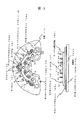
次に整流器であるダイオードの冷却について図2を用いて詳細に説明する。
【0048】
図1で示したように全波整流回路のダイオードは、固定子巻線が△結線の場合には6個、Y結線の場合には中性点ダイオードを2個用いるために8個で構成される。本実施形態ではY結線を例に取り説明する。
【0049】
ダイオードマイナスフィン109bにはダイオードU-,V-,N-,W-の4個がダイオードマイナスフィン109bに圧入されている。また、ダイオードプラスフィン109aにおいても同様にU+,V+,N+,W+の4個のダイオードが圧入されている。そして、ダイオードのマイナスフィン109bの上に絶縁材109abを介して、ダイオードプラスフィン109aが重なる構成である。
【0050】
そして、それらのダイオードは点線で図示したようにダイオードのU- のダイオードリード122とダイオードU+ のリードはターミナル121で接続されている。
【0051】
また、このターミナルのターミナル固定部材から出ている部分は固定子巻線の出力線と接続される。よって、ダイオードのU- はリードの部分はカソードに相当し、フィンに圧入されている側はアノードとなる。また、U+ のダイオードはリード側がアノード、プラスフィン側がカソードに相当する。
【0052】
そして、これらのダイオードマイナスフィン109b,絶縁材109ab,プラスフィン109a,ターミナル121,ターミナル固定部材109tは、絶縁材料であり熱伝導率の高い良熱伝導体116により一体成型されている。よって、防水特性に優れると共に内部の電圧は絶縁されるために図1に示したようにリアブラケットに直に接して配置することができる。
【0053】
発熱の最も大きい部分は、電流密度の高いダイオードのリード122部分及びターミナル121部分である。特に、ターミナル121はターミナル固定部材109tにより固定されると共に放熱が阻害されているために温度上昇が最も大きい。
【0054】
実験による測定ではターミナル121の温度はダイオードの温度に比べ約35℃程度高くなっていた。本実施形態のように良熱伝導体116で囲いリアブラケットに接触させることで、ターミナルの温度を約60℃下げることができた。
【0055】
また、本発明では、先に説明したターミナル121は固有抵抗値の小さい銅を用いたが、銅に他の金属を混ぜた銅合金を用いても同様の効果は得られる。
【0056】
また、冷却効率を上げるためにダイオードを圧入しているプラスフィン及びマイナスフィンの材質に同様の銅又は銅合金を用いることで達成できる。
【0057】
なお、本発明ではターミナルを保持するためにターミナル固定部材109tを用いたが使用しなくてもよい。
【0058】
次に図3を用いてダイオードのマイナス素子をリアプレート112に配置した場合について説明する。
【0059】
図2との違いは、ダイオードのマイナスフィン109bを省略してダイオードのマイナス素子を直接リアプレート112に圧入したものである。
【0060】
点線はリアプレート112により塞がれる水路を示したもので、ダイオードを良好に冷却できるものである。
【0061】
このように、ダイオードのマイナス素子をリアプレート112に直付けすることで熱抵抗を小さくすることができダイオードの温度上昇を下げることができる。言い換えると、ダイオードのマイナスフィン109bを水路を塞ぐための部材として使用したことにもなる。
【0062】
図4はその埋め込んだマイナス側のダイオードの断面図を示したものである。構成については図1に示したようにハウジング115の反プーリ側に配置した冷却促進部119R内の水路114を密閉するための部材である。
【0063】
リアプレート112を省略してダイオードのマイナスフィン109bにダイオードのマイナス側を配置している。そのマイナス側フィン109bの上部には絶縁材109abを介してダイオードのプラスフィン109aが配置される。
【0064】
このダイオードのプラスフィン109aにはダイオードのプラス側が配置され、それぞれのダイオードのリード122はターミナル121により接続されている。
【0065】
このように、リアプレート112を省略することでダイオードから水路114までの熱抵抗とリアプレート112とリアプレート112とマイナスフィン109bとの接触熱抵抗を低減できる効果がある。
【0066】
図5はリアプレート112に、マイナス側ダイオードだけではなくプラス側ダイオードを混在させた場合を示したものである。
【0067】
この場合は、プラス側ダイオードのディスク109dを電気的に絶縁する必要があるためディスク109dの外周部分には絶縁材109abが配置される。この絶縁材109abは熱伝導特性の良いものを使用することはいうまでもない。先の図2ではリアプレート112の上にダイオードマイナスフィン109bの上部にダイオードプラスフィンを絶縁材109abを用いて重ねて配置したが、他の方法としてはリアプレート112に対してマイナスダイオードは直付け、プラスフィンは絶縁材109abを介して直接リアプレート112に固定することも可能である。
【0068】
こうすることで、ダイオードのプラスフィン109aは絶縁物のみで水路に近いリアプレート112に接することができ良好な冷却が可能になる。
【0069】
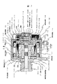
図6は、図1に示した車両用交流発電機1の縦断面図を示したものである。図1と同符号は同じものを示すため詳細な説明は省略する。
【0070】
図1との違いはプーリ側に配置したベアリング100Fの外輪の回り止めに設けているベアリングリテーナ120を省略し冷却促進部119Fを大きくしてベアリングのリテーナと共用化したものである。この冷却促進部119Fはアルミ部材で構成されフロントブラケット103にネジにより固定される。
【0071】
このように、冷却促進部119Fをロータの内周側にまで配置できることでロータの界磁巻線107の冷却を促進できる効果がある。フロントブラケット103に設けた冷却促進部119Fの高さをH1、界磁巻線の巻高さH2、反プーリ側に配置した冷却促進部119Rの高さをH3とした場合、それぞれの冷却促進部の高さは以下の式を満足するものとする。
【0072】
H1≧H2,H3≧H2
また、突き合わせ面のギャップ長g1及びg2は0.3mm〜1.0mm程度である。この理由は界磁巻線107の放熱効果を十分に確保するためである。
【0073】
図7は、図6に示した車両用交流発電機1の縦断面図を示す。図6と同符号は同じものを示すため詳細な説明は省略する。
【0074】
図6との違いは界磁巻線107の口出し線107aを爪磁極の側面に溝を設けてその凹部に配線を埋め込んだものである。この口出し線107aと爪形磁極部の凹部はワニスにより固定されている。よって、回転子の反プーリ側の面は平面とすることができるために冷却促進部119Rの効果を十分発揮することができる。
【0075】
図6の場合には界磁巻線口出し線107aの外側と冷却促進部119Rのギャップ長を0.3mm に設定しても、口出し線の線径分はギャップ長が広がってしまうために実際のギャップ長は2mm程度になっていた。そのために反プーリ側の冷却促進部110Rの冷却効果は小さかった。
【0076】
また、ロータの爪磁極側面に界磁巻線を通すための凹部を爪磁極を成型するときに爪磁極の数ほど設けることで、組立時に界磁巻線とロータ爪磁極の位置合わせを必要としないため量産性向上の効果がある。
【0077】
また、使わない凹部はロータ外周に向かって放射状に配置されるため内扇ファンの機能を持たせることができるため、機内空気の攪拌が可能となり冷却促進の効果もある。
【0078】
図8は、図7に示した車両用交流発電機1の縦断面図を示す。図7と同符号は同じものを示すため詳細な説明は省略する。
【0079】
図7との違いはフロントブラケット103の固定子巻線106とほぼ同じ外径部に放熱用の開口部122を設けたものである。この開口部122は回転部分と直接接していないため異物が混入しても回転子が固着し難い利点がある。また、爪形磁極部による攪拌作用により機内の冷却に有効であることから、界磁巻線温度を低くすることが出来るため界磁巻線の信頼性向上効果及び爪磁極間に配置した永久磁石の高温減磁抑制効果がある。
【図面の簡単な説明】
【図1】車両用交流発電機の縦断面図を示す。
【図2】整流回路の全体構成上面図を示す。
【図3】整流回路の全体構成上面図を示す。
【図4】ダイオード部分の縦断面図を示す。
【図5】ダイオード部分の縦断面図を示す。
【図6】車両用交流発電機の縦断面図を示す。
【図7】車両用交流発電機の縦断面図を示す。
【図8】車両用交流発電機の縦断面図を示す。
【符号の説明】
1…車両用交流発電機、104…ブラケット、107…界磁巻線、109…ダイオード、114…冷却水路、116…良熱伝導体、119…冷却促進部、121…ターミナル、122…開口部、200…軸方向端部を構成する面、300…回転子コア。[0001]
BACKGROUND OF THE INVENTION
The present invention relates to a vehicular AC generator, and more particularly to a cooling technique thereof.
[0002]
[Prior art]
As a conventional cooling technique for an automotive alternator, there is one disclosed in Japanese Patent Application Laid-Open No. 62-217837.
[0003]
In this publication, as a cooling method for the rectifier, it is disclosed that one side of the rectifier is disposed so as to be in contact with the water channel.
[0004]
In addition, as a method for cooling the field winding, for a brushless structure in which the field winding does not rotate, the field winding is directly brought into contact with a good heat conductor to release heat to the water channel through the good heat conductor. Is disclosed.
[0005]
[Problems to be solved by the invention]
Since the prior art is configured to cool the rectifier from one side, it is difficult to cool the heat generated at the terminal for connecting the diode and the stator coil and the lead portion of the diode. Therefore, there is a problem that even if the diode itself can be cooled, the Joule heat generated at the connecting portions (terminal, lead) cannot be cooled.
[0006]
In addition, since the cooling cover and the rectifier that constitute the water channel are configured independently in the above-described prior art, there is a problem that heat resistance is large when heat is transmitted from the rectifier through the cooling cover, and cooling efficiency is poor. .
[0007]
The first problem to be solved by the present invention is to efficiently cool Joule heat generated in a diode as a rectifying element, a terminal used in a connecting portion, and a lead portion of the diode.
[0008]
The second problem to be solved by the present invention is not a brushless structure AC generator in which the field winding does not rotate as in the above publication, but an AC generator in which the field winding rotates. Is to efficiently cool the Joule heat.
[0009]
[Means for Solving the Problems]
The present invention relates to a rotor having a field winding, a plurality of magnetic poles, a shaft having a pulley at one end thereof, and an AC to the stator winding by magnetizing the plurality of magnetic poles by the field winding. A stator for generating a voltage, a housing for fixing the stator, a water channel provided on the side opposite to the pulley of the housing and formed by covering a recess formed in the housing with a rear plate, and the water channel of the rear plate A plurality of rectifying elements that are arranged on the surface opposite to the rectifier and that rectifies the AC voltage generated in the stator winding, and a rear bracket that is fixed to the non-pulley side of the housing so as to cover the plurality of rectifying elements, An automotive alternator having a plurality of rectifying elements molded and a heat conductor provided between the rectifying elements and a rear bracket.
[0010]
Further, the present invention is characterized in that an opening having an outer diameter substantially the same as that of the stator winding is provided in at least one of the two brackets covering both sides of the stator and the rotor in the axial direction. .
[0013]
DETAILED DESCRIPTION OF THE INVENTION
FIG. 1 is a longitudinal sectional view of an automotive alternator that constitutes an embodiment of the present invention.
[0014]
The
[0015]
A shaft 101 is supported at the center of both brackets via a pulley-side bearing 100F and an anti-pulley-side bearing 100R, a
[0016]
As described above, the pulley side bearing 100F is provided with the bearing retainer 120 on the
[0017]
The
[0018]
A brush 111 is slidably attached to the slip ring 110, and power is supplied from the brush 111 to a field winding 107 described later via a field winding
[0019]
A rotor (rotor) is attached to the central portion of the shaft 101. A pair of claw-shaped
[0020]
A field winding 107 is wound around the center of the rotor, and the claw-shaped
[0021]
A
[0022]
A
[0023]
This mechanical gap length is a predetermined interval required from the relationship of mechanical characteristics, and is generally about 0.4 to 0.6 mm. Teeth and slots are arranged in the
[0024]
The
[0025]
The
[0026]
A sealing material (not shown) for preventing water leakage is arranged between the
[0027]
Inside the non-pulley side
[0028]
Further, the
[0029]
The
[0030]
These diodes convert the three-phase AC voltage generated in the stator winding 106 into a DC voltage by full-wave rectification.
[0031]
The
[0032]
Further, the
[0033]
Of the casing members facing the
[0034]
In the
[0035]
The magnetic flux generated by the field winding 107 forms a magnetic circuit in which the magnetic flux output from the claw portion of the N-pole claw-shaped magnetic pole portion passes through the
[0036]
This three-phase induced voltage is full-wave rectified and converted into a DC voltage by the diode group arranged on the previous diode plus
[0037]
The permanent magnets arranged between the claw magnetic poles described above are magnetized in the direction in which the same poles face each other between the claw magnetic poles, and are for increasing the effective magnetic flux passing through the stator winding.
[0038]
In this embodiment, since water cooling is adopted as a cooling method, a cooling effect can be expected even when power is generated at a low speed. Therefore, a highly heat-resistant neodymium magnet is adopted between the claw magnetic poles.
[0039]
Next, cooling of heat generation due to copper loss generated in the stator winding 106 will be described.
[0040]
As described above, the
[0041]
A plurality of holes pass through the outer periphery of the
Further, the heat generated by the copper loss of the field winding 107 generated inside the rotor is a cooling promotion portion that is in contact with the
[0042]
In this way, by arranging the axial surface and the outer peripheral surface so as to be indirectly in contact with the
[0043]
Although not shown, in the present invention, the even number of water channels arranged in the
[0044]
Thus, by setting the water channel to an even number, it is possible to provide water supply / drainage piping in the same direction, and the
[0045]
In addition, the possibility of entanglement with the belt can be greatly reduced by arranging the hose joint for water supply / drainage on the side opposite to the pulley.
[0046]
In the above description, the
[0047]
Next, cooling of the diode as a rectifier will be described in detail with reference to FIG.
[0048]
As shown in FIG. 1, the diode of the full-wave rectifier circuit is composed of 6 diodes when the stator winding is △ -connected and 8 neutral diodes when Y-connected. The In the present embodiment, the Y connection will be described as an example.
[0049]
Four diodes U − , V − , N − and W − are press-fitted into the diode minus
[0050]
Then, U of those diodes as is illustrated by dotted lines diode - diode lead 122 and the diode U + leads are connected by the terminal 121.
[0051]
The portion of the terminal that protrudes from the terminal fixing member is connected to the output line of the stator winding. Accordingly, the lead portion of U − of the diode corresponds to the cathode, and the side press-fitted into the fin serves as the anode. In the U + diode, the lead side corresponds to the anode, and the plus fin side corresponds to the cathode.
[0052]
The diode minus
[0053]
The portions with the largest heat generation are the lead 122 portion and the terminal 121 portion of the diode having a high current density. In particular, since the terminal 121 is fixed by the terminal fixing member 109t and the heat dissipation is hindered, the temperature rise is greatest.
[0054]
In the measurement by experiment, the temperature of the terminal 121 was about 35 ° C. higher than the temperature of the diode. The temperature of the terminal could be lowered by about 60 ° C. by contacting the rear bracket with the good
[0055]
In the present invention, the terminal 121 described above uses copper having a small specific resistance value. However, the same effect can be obtained by using a copper alloy obtained by mixing copper with another metal.
[0056]
Moreover, in order to raise cooling efficiency, it can achieve by using the same copper or copper alloy for the material of the plus fin and the minus fin which press-fit the diode.
[0057]
In the present invention, the terminal fixing member 109t is used to hold the terminal, but it may not be used.
[0058]
Next, a case where a negative element of a diode is arranged on the
[0059]
The difference from FIG. 2 is that the
[0060]
A dotted line indicates a water channel blocked by the
[0061]
Thus, by directly attaching the negative element of the diode to the
[0062]
FIG. 4 shows a cross-sectional view of the embedded negative diode. As shown in FIG. 1, the structure is a member for sealing the
[0063]
The
[0064]
The positive side of the diode is arranged on the
[0065]
Thus, by omitting the
[0066]
FIG. 5 shows a case where not only the minus side diode but also the plus side diode are mixed in the
[0067]
In this case, since it is necessary to electrically insulate the
[0068]
By doing so, the
[0069]
FIG. 6 is a longitudinal sectional view of the
[0070]
The difference from FIG. 1 is that the bearing retainer 120 provided in the rotation stop of the outer ring of the
[0071]
As described above, the cooling promotion part 119F can be arranged up to the inner peripheral side of the rotor, so that the cooling of the field winding 107 of the rotor can be promoted. When the height of the cooling promotion part 119F provided on the
[0072]
H1 ≧ H2, H3 ≧ H2
Moreover, the gap lengths g1 and g2 of the butted surfaces are about 0.3 mm to 1.0 mm. This is because the heat dissipation effect of the field winding 107 is sufficiently secured.
[0073]
FIG. 7 shows a longitudinal sectional view of the
[0074]
The difference from FIG. 6 is that the
[0075]
In the case of FIG. 6, even if the gap length between the outside of the field winding
[0076]
In addition, the number of claw magnetic poles when the claw magnetic poles are formed on the side surfaces of the claw magnetic poles of the rotor is set as many as the number of claw magnetic poles. This has the effect of improving mass productivity.
[0077]
In addition, since the concave portions that are not used are arranged radially toward the outer periphery of the rotor, the function of the internal fan can be provided, so that the air in the apparatus can be agitated and the cooling can be promoted.
[0078]
FIG. 8 shows a longitudinal sectional view of the
[0079]
The difference from FIG. 7 is that a
[Brief description of the drawings]
FIG. 1 is a longitudinal sectional view of an automotive alternator.
FIG. 2 is a top view of the overall configuration of a rectifier circuit.
FIG. 3 is a top view of the overall configuration of a rectifier circuit.
FIG. 4 is a longitudinal sectional view of a diode portion.
FIG. 5 is a longitudinal sectional view of a diode portion.
FIG. 6 is a longitudinal sectional view of an automotive alternator.
FIG. 7 is a longitudinal sectional view of an automotive alternator.
FIG. 8 is a longitudinal sectional view of an automotive alternator.
[Explanation of symbols]
DESCRIPTION OF
Claims (9)
前記界磁巻線により前記複数の磁極を磁化することによって固定子巻線に交流電圧を発生する固定子と、
前記固定子を固定するハウジングと、
前記ハウジングの反プーリ側に設けられ、前記ハウジングに形成された凹部をリアプレートによって蓋することによって形成された水路と、
前記リアプレートの前記水路とは反対側の面に配置され、前記固定子巻線に発生した交流電圧を整流する複数の整流素子と、
前記複数の整流素子を覆うように、前記ハウジングの反プーリ側に固定されたリアブラケットと、
前記複数の整流素子をモールドし、前記整流素子と前記リアブラケットとの間に設けられた熱伝導体と、
を有する車両用交流発電機。 A rotor having a field winding, a plurality of magnetic poles, and a shaft having a pulley at one end ;
A stator for generating an AC voltage in the stator winding by magnetizing a plurality of magnetic poles by the field winding,
And Ruha Ujingu to fix the stator,
A water passage formed on the side opposite to the pulley of the housing and formed by covering a recess formed in the housing with a rear plate;
A plurality of rectifying elements that are arranged on a surface of the rear plate opposite to the water channel and rectify an AC voltage generated in the stator winding;
A rear bracket fixed on the side opposite to the pulley of the housing so as to cover the plurality of rectifying elements;
Molding the plurality of rectifying elements, a thermal conductor provided between the rectifying elements and the rear bracket,
A vehicle alternator having
前記整流素子は、前記熱伝導体を介して前記リアブラケットに接触している車両用交流発電機。The rectifying element is an AC generator for a vehicle that is in contact with the rear bracket via the thermal conductor.
前記整流素子は正極側整流素子と、負極側整流素子とを含み、The rectifying element includes a positive electrode side rectifying element and a negative electrode side rectifying element,
前記正極側整流素子と、前記負極側整流素子との間を絶縁するための絶縁材を、前記リアプレートに設けた車両用交流発電機。An automotive alternator in which an insulating material for insulating the positive side rectifying element and the negative side rectifying element is provided on the rear plate.
前記リアプレートはプラスフィンとマイナスフィンから成り、The rear plate is composed of a plus fin and a minus fin,
前記プラスフィンには前記正極側整流素子、前記マイナスフィンには前記負極側整流素子が設けられるともに、前記絶縁材は前記プラスフィンと前記マイナスフィンの間に設けられている車両用交流発電機。The positive fin rectifying element is provided on the plus fin, the negative rectifying element is provided on the minus fin, and the insulating material is provided between the plus fin and the minus fin.
前記ハウジングには、前記界磁巻線の巻線厚み以上の厚みを有する冷却促進部が設けられていることを特徴とする車両用交流発電機。In the vehicle alternator according to claim 1,
The vehicle alternator according to claim 1, wherein the housing is provided with a cooling promoting portion having a thickness equal to or larger than a winding thickness of the field winding.
前記回転子のシャフトを支持するベアリングを有し、
前記冷却促進部は、前記ベアリングのリテーナを兼ねていることを特徴とする車両用交流発電機。In the vehicle AC generator according to claim 5,
A bearing for supporting the rotor shaft;
The AC generator for a vehicle, wherein the cooling promoting portion also serves as a retainer for the bearing.
前記界磁巻線は口出し線を備えており、
前記口出し線は前記回転子のコア側面に埋め込まれていることを特徴とする車両用交流発電機。In the vehicle AC generator according to claim 5,
The field winding has a lead wire;
The vehicle alternator according to claim 1, wherein the lead wire is embedded in a core side surface of the rotor.
前記整流素子は、前記整流回路と前記固定子の巻線とを電気的に接続するためのターミナルを備えており、
前記ターミナルは銅又は銅合金のものであることを特徴とする車両用交流発電機。In the vehicle alternator according to claim 1,
The rectifier element includes a terminal for electrically connecting the rectifier circuit and the stator winding,
The vehicle AC generator, wherein the terminal is made of copper or a copper alloy.
前記ハウジングのプーリ側に固定されたフロントブラケットを有し、
前記リアブラケットまたは前記フロントブラケットの2つのブラケットのうち、少なくとも1つのブラケットには、前記固定子の巻線とほぼ同じ外径の開口部が設けられていることを特徴とする車両用交流発電機。In the vehicle alternator according to claim 1,
A front bracket fixed to the pulley side of the housing;
An AC generator for a vehicle, characterized in that at least one of the two brackets of the rear bracket or the front bracket is provided with an opening having an outer diameter substantially the same as the winding of the stator. .
Priority Applications (1)
| Application Number | Priority Date | Filing Date | Title |
|---|---|---|---|
| JP26318199A JP4258909B2 (en) | 1999-09-17 | 1999-09-17 | Vehicle alternator |
Applications Claiming Priority (1)
| Application Number | Priority Date | Filing Date | Title |
|---|---|---|---|
| JP26318199A JP4258909B2 (en) | 1999-09-17 | 1999-09-17 | Vehicle alternator |
Related Child Applications (1)
| Application Number | Title | Priority Date | Filing Date |
|---|---|---|---|
| JP2006075875A Division JP2006158200A (en) | 2006-03-20 | 2006-03-20 | Ac generator for vehicle |
Publications (3)
| Publication Number | Publication Date |
|---|---|
| JP2001086706A JP2001086706A (en) | 2001-03-30 |
| JP2001086706A5 JP2001086706A5 (en) | 2005-11-17 |
| JP4258909B2 true JP4258909B2 (en) | 2009-04-30 |
Family
ID=17385903
Family Applications (1)
| Application Number | Title | Priority Date | Filing Date |
|---|---|---|---|
| JP26318199A Expired - Fee Related JP4258909B2 (en) | 1999-09-17 | 1999-09-17 | Vehicle alternator |
Country Status (1)
| Country | Link |
|---|---|
| JP (1) | JP4258909B2 (en) |
Families Citing this family (8)
| Publication number | Priority date | Publication date | Assignee | Title |
|---|---|---|---|---|
| US6992409B2 (en) | 2002-03-15 | 2006-01-31 | Denso Corporation | Liquid-cooled rotary electric machine integrated with an inverter |
| JP3770200B2 (en) | 2002-04-26 | 2006-04-26 | 株式会社日立製作所 | AC generator for vehicles |
| JP3775348B2 (en) | 2002-05-31 | 2006-05-17 | 株式会社日立製作所 | Rotating electric machine |
| JP4692439B2 (en) * | 2006-08-22 | 2011-06-01 | 株式会社デンソー | AC generator for vehicles |
| JP4433023B2 (en) | 2007-09-05 | 2010-03-17 | 株式会社デンソー | Vehicle alternator |
| JP5492170B2 (en) * | 2011-10-06 | 2014-05-14 | 株式会社神戸製鋼所 | Power generator |
| JP5705259B2 (en) * | 2013-04-09 | 2015-04-22 | 三菱電機株式会社 | Stator core fixing structure of rotating electric machine |
| CN117439336B (en) * | 2023-12-20 | 2024-03-12 | 深圳市三利达电器科技有限公司 | Capacitive low-noise motor and chef machine |
-
1999
- 1999-09-17 JP JP26318199A patent/JP4258909B2/en not_active Expired - Fee Related
Also Published As
| Publication number | Publication date |
|---|---|
| JP2001086706A (en) | 2001-03-30 |
Similar Documents
| Publication | Publication Date | Title |
|---|---|---|
| EP0751601B1 (en) | Motor vehicle alternator having sealed rectifiers for efficient high-temperature operation | |
| JP5401367B2 (en) | AC generator for vehicles | |
| JP3612807B2 (en) | Rotating electrical machine for water pump integrated vehicle | |
| JP3985760B2 (en) | Rotating electrical machine system | |
| JP3443363B2 (en) | AC generator for vehicles | |
| US9484787B2 (en) | Voltage regulator device for rotary electric machine, bearing for rotary electric machine and rotary electric machine comprising such bearing | |
| EP1089417A2 (en) | An alternating current dynamo for a vehicle | |
| US7015607B1 (en) | AC generator for vehicle | |
| JP2002153030A (en) | Alternator for vehicle | |
| KR20000056999A (en) | Alternating current generator for vehicle | |
| KR101892314B1 (en) | Voltage regulator device for a rotary electric machine, bearing for such a machine equipped with such a device and such a machine comprising such a bearing | |
| KR100874317B1 (en) | Car alternator | |
| KR20010014556A (en) | Automotive alternator | |
| US6018205A (en) | Vehicle alternator | |
| JP4258909B2 (en) | Vehicle alternator | |
| JP4575385B2 (en) | AC generator rectifier | |
| JP2003204656A (en) | Alternator for vehicle | |
| JP4450134B2 (en) | Brushless alternator | |
| JP3531544B2 (en) | Alternator | |
| EP0980132B1 (en) | AC generator for vehicle | |
| JP4023489B2 (en) | Automotive alternator | |
| JP2006158200A (en) | Ac generator for vehicle | |
| CN108886300B (en) | Rotating electrical machine | |
| JP2000245111A (en) | Alternating current generator for vehicles | |
| JPH08275442A (en) | Ac generator for vehicle |
Legal Events
| Date | Code | Title | Description |
|---|---|---|---|
| A521 | Written amendment |
Free format text: JAPANESE INTERMEDIATE CODE: A523 Effective date: 20050928 |
|
| A621 | Written request for application examination |
Free format text: JAPANESE INTERMEDIATE CODE: A621 Effective date: 20050928 |
|
| RD01 | Notification of change of attorney |
Free format text: JAPANESE INTERMEDIATE CODE: A7421 Effective date: 20060417 |
|
| A131 | Notification of reasons for refusal |
Free format text: JAPANESE INTERMEDIATE CODE: A131 Effective date: 20080924 |
|
| A521 | Written amendment |
Free format text: JAPANESE INTERMEDIATE CODE: A523 Effective date: 20081125 |
|
| TRDD | Decision of grant or rejection written | ||
| A01 | Written decision to grant a patent or to grant a registration (utility model) |
Free format text: JAPANESE INTERMEDIATE CODE: A01 Effective date: 20090120 |
|
| A01 | Written decision to grant a patent or to grant a registration (utility model) |
Free format text: JAPANESE INTERMEDIATE CODE: A01 |
|
| A61 | First payment of annual fees (during grant procedure) |
Free format text: JAPANESE INTERMEDIATE CODE: A61 Effective date: 20090202 |
|
| FPAY | Renewal fee payment (event date is renewal date of database) |
Free format text: PAYMENT UNTIL: 20120220 Year of fee payment: 3 |
|
| FPAY | Renewal fee payment (event date is renewal date of database) |
Free format text: PAYMENT UNTIL: 20120220 Year of fee payment: 3 |
|
| FPAY | Renewal fee payment (event date is renewal date of database) |
Free format text: PAYMENT UNTIL: 20120220 Year of fee payment: 3 |
|
| S111 | Request for change of ownership or part of ownership |
Free format text: JAPANESE INTERMEDIATE CODE: R313111 |
|
| FPAY | Renewal fee payment (event date is renewal date of database) |
Free format text: PAYMENT UNTIL: 20120220 Year of fee payment: 3 |
|
| R350 | Written notification of registration of transfer |
Free format text: JAPANESE INTERMEDIATE CODE: R350 |
|
| FPAY | Renewal fee payment (event date is renewal date of database) |
Free format text: PAYMENT UNTIL: 20120220 Year of fee payment: 3 |
|
| FPAY | Renewal fee payment (event date is renewal date of database) |
Free format text: PAYMENT UNTIL: 20130220 Year of fee payment: 4 |
|
| FPAY | Renewal fee payment (event date is renewal date of database) |
Free format text: PAYMENT UNTIL: 20130220 Year of fee payment: 4 |
|
| FPAY | Renewal fee payment (event date is renewal date of database) |
Free format text: PAYMENT UNTIL: 20140220 Year of fee payment: 5 |
|
| LAPS | Cancellation because of no payment of annual fees |