JP4255443B2 - Display method for display device and display device - Google Patents
Display method for display device and display device Download PDFInfo
- Publication number
- JP4255443B2 JP4255443B2 JP2004556239A JP2004556239A JP4255443B2 JP 4255443 B2 JP4255443 B2 JP 4255443B2 JP 2004556239 A JP2004556239 A JP 2004556239A JP 2004556239 A JP2004556239 A JP 2004556239A JP 4255443 B2 JP4255443 B2 JP 4255443B2
- Authority
- JP
- Japan
- Prior art keywords
- image
- reference position
- distance
- pointer
- tip
- Prior art date
- Legal status (The legal status is an assumption and is not a legal conclusion. Google has not performed a legal analysis and makes no representation as to the accuracy of the status listed.)
- Expired - Fee Related
Links
Images


Classifications
-
- A—HUMAN NECESSITIES
- A61—MEDICAL OR VETERINARY SCIENCE; HYGIENE
- A61B—DIAGNOSIS; SURGERY; IDENTIFICATION
- A61B17/00—Surgical instruments, devices or methods, e.g. tourniquets
- A61B17/16—Bone cutting, breaking or removal means other than saws, e.g. Osteoclasts; Drills or chisels for bones; Trepans
- A61B17/17—Guides or aligning means for drills, mills, pins or wires
- A61B17/1714—Guides or aligning means for drills, mills, pins or wires for applying tendons or ligaments
-
- A—HUMAN NECESSITIES
- A61—MEDICAL OR VETERINARY SCIENCE; HYGIENE
- A61B—DIAGNOSIS; SURGERY; IDENTIFICATION
- A61B34/00—Computer-aided surgery; Manipulators or robots specially adapted for use in surgery
- A61B34/20—Surgical navigation systems; Devices for tracking or guiding surgical instruments, e.g. for frameless stereotaxis
-
- A—HUMAN NECESSITIES
- A61—MEDICAL OR VETERINARY SCIENCE; HYGIENE
- A61B—DIAGNOSIS; SURGERY; IDENTIFICATION
- A61B17/00—Surgical instruments, devices or methods, e.g. tourniquets
- A61B17/16—Bone cutting, breaking or removal means other than saws, e.g. Osteoclasts; Drills or chisels for bones; Trepans
- A61B17/17—Guides or aligning means for drills, mills, pins or wires
- A61B17/1739—Guides or aligning means for drills, mills, pins or wires specially adapted for particular parts of the body
- A61B17/1764—Guides or aligning means for drills, mills, pins or wires specially adapted for particular parts of the body for the knee
-
- A—HUMAN NECESSITIES
- A61—MEDICAL OR VETERINARY SCIENCE; HYGIENE
- A61B—DIAGNOSIS; SURGERY; IDENTIFICATION
- A61B34/00—Computer-aided surgery; Manipulators or robots specially adapted for use in surgery
- A61B34/10—Computer-aided planning, simulation or modelling of surgical operations
- A61B2034/101—Computer-aided simulation of surgical operations
- A61B2034/105—Modelling of the patient, e.g. for ligaments or bones
-
- A—HUMAN NECESSITIES
- A61—MEDICAL OR VETERINARY SCIENCE; HYGIENE
- A61B—DIAGNOSIS; SURGERY; IDENTIFICATION
- A61B34/00—Computer-aided surgery; Manipulators or robots specially adapted for use in surgery
- A61B34/10—Computer-aided planning, simulation or modelling of surgical operations
- A61B2034/107—Visualisation of planned trajectories or target regions
-
- A—HUMAN NECESSITIES
- A61—MEDICAL OR VETERINARY SCIENCE; HYGIENE
- A61B—DIAGNOSIS; SURGERY; IDENTIFICATION
- A61B34/00—Computer-aided surgery; Manipulators or robots specially adapted for use in surgery
- A61B34/20—Surgical navigation systems; Devices for tracking or guiding surgical instruments, e.g. for frameless stereotaxis
- A61B2034/2046—Tracking techniques
- A61B2034/2055—Optical tracking systems
-
- A—HUMAN NECESSITIES
- A61—MEDICAL OR VETERINARY SCIENCE; HYGIENE
- A61B—DIAGNOSIS; SURGERY; IDENTIFICATION
- A61B34/00—Computer-aided surgery; Manipulators or robots specially adapted for use in surgery
- A61B34/20—Surgical navigation systems; Devices for tracking or guiding surgical instruments, e.g. for frameless stereotaxis
- A61B2034/2068—Surgical navigation systems; Devices for tracking or guiding surgical instruments, e.g. for frameless stereotaxis using pointers, e.g. pointers having reference marks for determining coordinates of body points
-
- A—HUMAN NECESSITIES
- A61—MEDICAL OR VETERINARY SCIENCE; HYGIENE
- A61B—DIAGNOSIS; SURGERY; IDENTIFICATION
- A61B34/00—Computer-aided surgery; Manipulators or robots specially adapted for use in surgery
- A61B34/20—Surgical navigation systems; Devices for tracking or guiding surgical instruments, e.g. for frameless stereotaxis
- A61B2034/2072—Reference field transducer attached to an instrument or patient
-
- A—HUMAN NECESSITIES
- A61—MEDICAL OR VETERINARY SCIENCE; HYGIENE
- A61B—DIAGNOSIS; SURGERY; IDENTIFICATION
- A61B34/00—Computer-aided surgery; Manipulators or robots specially adapted for use in surgery
- A61B34/25—User interfaces for surgical systems
-
- A—HUMAN NECESSITIES
- A61—MEDICAL OR VETERINARY SCIENCE; HYGIENE
- A61B—DIAGNOSIS; SURGERY; IDENTIFICATION
- A61B90/00—Instruments, implements or accessories specially adapted for surgery or diagnosis and not covered by any of the groups A61B1/00 - A61B50/00, e.g. for luxation treatment or for protecting wound edges
- A61B90/36—Image-producing devices or illumination devices not otherwise provided for
- A61B90/37—Surgical systems with images on a monitor during operation
Abstract
Description
本発明は、医療用の設備に関し、さらに詳しくは位置確認装置の情報を表示するための方法及び装置に関する。 The present invention relates to medical equipment, and more particularly to a method and apparatus for displaying information of a position confirmation device.
位置確認装置が、例えば前十字靱帯(ACL)修復手術などの外科手術の実施において、外科医を補助するために開発されてきている。ACL手術に使用される場合、骨へと取り付けられたマーカを立体カメラ・システムによって観測することができ、立体カメラ・システムへと接続されたデータ処理システムが、それぞれの骨について座標参照系を設定するため、空間内におけるマーカの位置を記録する。追加のマーカが、骨の特定の目印を触診(接触)するように使用され、骨の座標参照系における当該目印の位置が確認される。手術において外科医のガイドに使用すべく、座標参照系及び目印にもとづく骨の画像を表示するため、モニタが使用される。或る特定の位置確認装置についての説明が、Cinquinらの米国特許第6,385,475号に開示されており、この米国特許は、ここでの言及によって全体が本明細書に組み込まれたものとする。 Localization devices have been developed to assist surgeons in performing surgical procedures such as, for example, anterior cruciate ligament (ACL) repair procedures. When used in ACL surgery, markers attached to bones can be observed by a stereoscopic camera system, and a data processing system connected to the stereoscopic camera system sets a coordinate reference system for each bone Therefore, the marker position in the space is recorded. An additional marker is used to palpate (contact) a particular landmark on the bone to ascertain the position of that landmark in the bone coordinate reference system. A monitor is used to display an image of the bone based on the coordinate reference system and landmarks for use as a surgeon's guide in surgery. A description of one particular location device is disclosed in US Pat. No. 6,385,475 to Cinquin et al., Which is hereby incorporated by reference herein in its entirety. And
ACL手術の一ステップにおいては、置換用ACLの一端を収容するための脛骨トンネルが穿孔されたのち、ACLの他端を取り付けるための穴、すなわち大腿骨トンネルを穿孔するため、位置確認装置が大腿骨表面の基準位置を計算する。特に、大腿骨トンネルは、修復されたACLに最良の等尺性がもたらされる(すなわち、膝関節の屈伸の全範囲にわたって、修復ACLの脛骨への挿入位置と大腿骨への挿入位置との間の距離の変化が最小である)位置に配置されなければならない。最良の等尺性にのみもとづく基準位置は、大腿骨トンネルにとって最適な位置でない場合もある。大腿骨トンネルの最適位置の決定においては、他の条件も考慮しなければならない。大腿骨上で等尺性が最大である点の近傍にある他の点が、適切な等尺性をもたらしうる。したがって、外科医は、通常は、すべての条件間の最も良好な妥協がもたらされる大腿骨トンネルのための最適位置を、基準位置の近傍で選択する。 In one step of the ACL operation, a tibial tunnel for receiving one end of the replacement ACL is drilled, and then a hole for attaching the other end of the ACL, that is, a femoral tunnel is drilled. Calculate the reference position of the bone surface. In particular, the femoral tunnel provides the best isometricity for the repaired ACL (ie, between the insertion position of the repair ACL on the tibia and the insertion position on the femur over the entire range of knee joint flexion and extension). The distance change of the A reference position based only on the best isometricity may not be the optimal position for the femoral tunnel. Other conditions must be taken into account in determining the optimal position of the femoral tunnel. Other points in the vicinity of the point that is isometric on the femur may provide adequate isometricity. Thus, the surgeon typically selects the optimal position for the femoral tunnel that provides the best compromise between all conditions, in the vicinity of the reference position.
現在のところ、外科医は、大腿骨トンネルのための最適位置を、位置確認装置の助けによって選択している。外科医は、ポインタの先端を、位置確認装置からの指示及び手術についての自身の知識にもとづき、基準位置のほぼ近傍に配置する。ポインタは、位置確認装置によって追跡できるマーカを有している。位置確認装置は、マーカに対するポインタ先端の向き及び位置を示すデータでプログラムされている。マーカを観測することによって、位置確認装置は、大腿骨表面に対するポインタ先端の位置を割り出すことができる。 At present, surgeons have chosen the optimal position for the femoral tunnel with the aid of a localization device. The surgeon places the tip of the pointer in the vicinity of the reference position based on the instruction from the position confirmation device and his knowledge about the operation. The pointer has a marker that can be tracked by the position confirmation device. The position confirmation device is programmed with data indicating the direction and position of the tip of the pointer with respect to the marker. By observing the marker, the position confirmation device can determine the position of the tip of the pointer with respect to the femur surface.
位置確認装置は、大腿骨表面の一部分について拡大された視覚画像を、大腿骨表面上のポインタ先端の位置を表すインジケータとともに、モニタ上に表示する。さらに、位置確認装置は、大腿骨上のポインタ先端に対応する位置についての等尺性を、大腿骨トンネルの最適位置の割り出しのための他の公知の条件に関する情報とともに表示する。最初に、視覚画像及び表示された等尺性をガイドとして使用し、外科医は、大腿骨表面を巡ってポインタ先端を動かし、等尺性が最大である基準位置の周囲の領域に位置しているであろう等尺性が良好な領域を、物理的に探索する。次いで、外科医は、位置確認装置からフィードバックされた等尺性及び他の条件についての情報を確認しつつ、基準位置のほぼ近傍、例えば10mmの範囲で、ポインタ先端を移動させる。最後に、外科医は、確認したフィードバックに基づいて、大腿骨トンネルのための最適位置を選択する。 The position confirmation device displays a magnified visual image of a part of the femur surface on a monitor together with an indicator indicating the position of the pointer tip on the femur surface. Further, the position confirmation device displays the isometricity of the position corresponding to the pointer tip on the femur along with information on other known conditions for determining the optimal position of the femoral tunnel. Initially, using the visual image and the displayed isometric as a guide, the surgeon moves the tip of the pointer around the femoral surface and is located in a region around the reference position where the isometric is maximal An area of good isometricity that would be physically searched. Next, the surgeon moves the tip of the pointer within the vicinity of the reference position, for example, in the range of 10 mm, while confirming information on isometricity and other conditions fed back from the position confirmation device. Finally, the surgeon selects the optimal position for the femoral tunnel based on the confirmed feedback.
基準位置の近傍の領域を探索し、基準位置近傍の各点を調査するために必要な程度の正確さをもたらすため、位置確認装置によって表示される拡大視覚画像の領域は、ポインタ先端の周囲の約1センチメートルの直径の領域を提示する。実際の骨の表面は、この表示領域に比べて大きく、したがって基準位置へと達するためにポインタを動かすべき方向を判断することが困難であり、外科医の側に試行錯誤を強いている。すなわち、拡大された表示領域を使用して基準位置を探し当てることは、外科医にとって厄介であり、時間がかかる。
したがって、基準位置の探索を補助する表示方法及び表示装置へのニーズが存在する。本発明は、何よりもこのニーズを満足する。 Accordingly, there is a need for a display method and display device that assists in searching for a reference position. The present invention satisfies this need above all.
本発明は、位置確認装置によって追跡される器具と位置確認装置によって特定される基準位置との近接度合いに応じて異なる画像を表示することによって、前記課題を解決する表示方法及び表示装置を提供する。この位置確認装置は、当該位置確認装置によって特定された基準位置と当該位置確認装置によって追跡されるポインタの先端との間の距離に応じて、例えば倍率の異なる別の画像を表示する。ポインタ先端と基準位置との近接度合いに応じて異なる画像を表示することで、基準位置の効率的な探索において外科医を補助できる画像が提示される。例えば、まず外科医に、ポインタ先端の大まかな位置決めに使用するための粗い画像を提示でき、ポインタ先端が基準位置から或る所定の距離の範囲内に位置するとき、外科医に、ポインタ先端の詳細な位置決めに使用するための精緻な画像を提示できる。本発明は、これに限られるわけではないが、ACL修復手術において大腿骨トンネルを穿孔するための最適位置を外科医が効率的に選択できるようにする用途に、特によく適している。 The present invention provides a display method and a display device that solve the above-described problems by displaying different images according to the degree of proximity between the instrument tracked by the position confirmation device and the reference position specified by the position confirmation device. . This position confirmation device displays, for example, another image with different magnifications according to the distance between the reference position specified by the position confirmation device and the tip of the pointer tracked by the position confirmation device. By displaying different images according to the degree of proximity between the pointer tip and the reference position, an image that can assist the surgeon in efficiently searching for the reference position is presented. For example, the surgeon can first be presented with a rough image for use in rough positioning of the pointer tip, and when the pointer tip is located within a certain predetermined distance from the reference position, the surgeon is given details of the pointer tip. A precise image for use in positioning can be presented. The present invention is particularly well-suited for, but not limited to, applications that allow a surgeon to efficiently select the optimal location for drilling a femoral tunnel in ACL repair surgery.
本発明の一態様は、基準位置を特定する位置確認装置とともに使用するための表示を生成する方法である。この方法は、ポインタ先端と基準位置との間の距離を監視すること、及び監視した距離に応じて、複数の画像のうちの1つを表示することを含む。 One aspect of the present invention is a method for generating a display for use with a position verification device that identifies a reference position. The method includes monitoring a distance between the pointer tip and a reference position and displaying one of the plurality of images depending on the monitored distance.
本発明の別の態様は、基準位置を特定する位置確認装置である。この位置確認装置は、ポインタ先端に関連付けられたマーカを追跡するためのセンサ、モニタ、及びポインタ先端と基準位置との間の距離を監視しかつ監視した距離に基づいて複数の画像からモニタ上に表示する画像を選択するためのセンサ及びモニタに組み合わされているコンピュータを有している。 Another aspect of the present invention is a position confirmation device that specifies a reference position. The position confirmation device monitors a distance between a pointer tip and a reference position, a sensor for tracking a marker associated with the pointer tip, and a plurality of images on the monitor based on the monitored distance. It has a computer combined with a sensor and a monitor for selecting an image to be displayed.
本発明の更に別の態様は、基準位置を特定する位置確認装置に画像を表示するためのコンピュータ・プログラム製品である。このコンピュータ・プログラム製品は、コンピュータで読み出し可能な媒体に具現化されたコンピュータで読解可能なプログラム・コードを含んでいる。このコンピュータで読解可能なプログラム・コードが、ポインタ先端と基準位置との間の距離を監視するためのコンピュータで読解可能なプログラム・コード、及び監視した距離に応じて複数の画像のうちの1つを表示するためのコンピュータで読解可能なプログラム・コードを含む。 Yet another aspect of the present invention is a computer program product for displaying an image on a position confirmation device that specifies a reference position. The computer program product includes computer readable program code embodied on a computer readable medium. The computer readable program code is a computer readable program code for monitoring the distance between the pointer tip and the reference position, and one of a plurality of images according to the monitored distance. Includes computer readable program code for displaying
図1は、本発明の方法を使用することができる位置確認装置110を示している。説明の目的で、ACL修復手術において、置換用ACLを接続するための脛骨トンネルを穿孔したのちの大腿骨104内のトンネルのための位置の選択に関して、本発明の好ましい実施の形態を説明する。
FIG. 1 shows a
図1には、脚102のACL修復手術を受ける患者100が、手術台108に横たわった状態で概略的に示されている。位置確認装置110は、外科手術のナビゲーションのためのソフトウェアが搭載されているコンピュータ112、マーカ116を検出することができる例えばカメラなどのセンサ114、及び大腿骨トンネルの穿孔位置の選択を助けるべく外科医に外科手術ナビゲーション情報を表示するためのモニタ118を備えている。センサ114は、患者の脚102がセンサ114の視野内にあるよう、患者100の上方かつ側方に配置されている。一般に、マーカ116が骨及び手術用の器具類に動かぬように取り付けられ、位置確認装置110によって、マーカ116が取り付けられている骨及び手術用器具類の正確な位置及び向きを追跡し、座標系を割り出すことができる。適切な位置確認装置110についての説明を、発明者の1人が本件出願と同じであって、本件出願と同じ団体に譲渡されているCinquin et al.の米国特許第6,385,475号に見つけることができる。
In FIG. 1, a
図2には、ポインタ202及び図1の大腿骨104の一部分204が示されており、図1及び図2において、同じ構成要素には同一の番号が付されている。ポインタ202は、位置確認装置110による追跡のためマーカ208を収容することができる。位置確認装置は、マーカ208に対するポインタ先端210の向き及び位置を示すデータがプログラムされている。マーカ208を観測することによって、位置確認装置110は、位置確認装置110にとって既知である他の点に対して、ポインタ先端210の位置及び向きを割り出すことができる。ポインタ202が、基本的には、空間内の一点を特定できる任意の装置であってよく、ポインタ先端210が、基本的には、そのような装置に組み合わされた特定可能な任意の位置であってよいことを、当業者であれば理解できるであろう。
FIG. 2 shows a
最初に、位置確認装置110によって基準位置206が特定される。説明の目的のため、基準位置206が大腿骨の一部分204に図として描かれているが、基準位置206の表示が大腿骨104上に実際に存在するわけではないことは、理解できるであろう。好ましくは、基準位置206は、位置確認装置110を使用して公知のやり方で前もってナビゲートされた脛骨トンネル(図示されていない)に関連して特定され、位置確認装置110が、脛骨のACL挿入位置などの脛骨トンネルに関する情報を保持している。位置確認装置を使用すると、基準位置206は、次のようにすることにより特定することができる。即ち、最初に、大腿骨104において置換用ACLの大腿骨への挿入位置として通常使用される領域、すなわち大腿骨104の顆間窩212内の領域をデジタル化し、公知の補間技術を用いて当該領域の連続画像を生成する。第2に、大腿骨座標系におけるACL脛骨挿入位置の軌跡が、脚102(図1)の屈伸の際に記録される。最後に、前記連続画像の各点に関して、その点とACL脛骨挿入領域の屈伸の際の軌跡との距離の差に相当する値が計算され、最小の差(すなわち、等尺性が最良)に相当する点が、基準位置として特定される。基準位置を特定するための方法の1つを、Bainville et al.の「膝の十字靱帯の大腿骨上への固定位置の決定のための方法及びシステム(Method and System for Determining the Fixation Point on the Femur of a Crossed Ligament of the Knee)」という名称の米国特許第5,564,437号に見つけることができ、この米国特許は、ここでの言及によってすべてが本明細書に組み込まれたものとする。
First, the
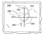
図2、3A及び3Bを参照すると、好ましい実施の形態においては、基準位置が特定されたのち、図3Aに描かれている粗い画像300などの第1の画像が、ポインタ先端210の粗い配置のため、モニタ118(図1)上で外科医に提示される。位置確認装置からの指示、提示された画像300、及び手術についての外科医の知識にもとづき、外科医は、ポインタ先端210を、例えば大腿骨204の顆間窩の基準位置206のほぼ近傍に位置させる。
Referring to FIGS. 2, 3A and 3B, in the preferred embodiment, after the reference position is identified, a first image, such as the
図3Aに示した画像において、大腿骨の画像302及び位置決めシステム304が表示されている。位置決めシステム304は、ポインタ先端210を基準位置206へと届けるための位置決めにおいて、十字線305ならびに下向き矢印306及び左向き矢印308などの矢印を使用して、外科医をガイドする。矢印は、大腿骨204の顆間窩に対するポインタ先端210の現在の位置を示している。好ましい実施の形態においては、上向き及び下向きの矢印が、それぞれ大腿骨204の顆間窩の基準位置206の右及び左の位置に相当する(すなわち、表示されている大腿骨画像302に対して直角)。例えば、粗い画像300に表示された下向きの矢印306は、ポインタ先端210が基準位置206の左側にあり、基準位置206へと達するために右側に動かす必要があることを、外科医に対して知らせている。好ましい実施の形態においては、左向き及び右向きの矢印が、それぞれ大腿骨204の顆間窩内の基準位置206の下方及び上方の位置に相当する方向を示している。例えば、左向きの矢印308は、ポインタ先端210が基準位置206よりも下方にあり、基準位置206へと達するために上方へと動かす必要があることを、外科医に対して知らせている。
In the image shown in FIG. 3A, a
或る実施の形態においては、粗い画像300内の大腿骨の画像302に関し、その位置及び向きが、粗い画像300内で変化することがない。他の実施の形態においては、大腿骨の画像302の位置、向き、及び/又は拡大率を、大腿骨204に対するポインタ先端210の位置に基づいて変化させることが考えられる。
In some embodiments, the position and orientation of the
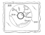
ポインタ先端210が、基準位置206から例えば2mmである第1の所定の距離の範囲内に移動したとき、図3Bに示した精緻な画像310などの第2の画像が、モニタ118(図1)上で外科医に提示される。精緻な画像310は、ポインタ先端210の周囲の大腿骨204の表面の拡大画像312を描いており、ポインタ先端210の詳細な位置決めに使用される。精緻な画像310には、大腿骨トンネルの切削に使用するドリルビット(図示されていない)の仮想の先端を表わす円314が表示されている。この円の中心がポインタ先端210に相当し、ドリルビットの中心を表わしており、この円の直径が、ドリルビットの直径を表わしている。
When the
一実施の形態においては、精緻な画像310に表示された拡大画像312が、ポインタ先端210が大腿骨204の表面に沿って動かされると更新され、画面の中央が、大腿骨204の表面のポインタ先端210が位置している位置に対応する。他の実施の形態においては、画面の中央が基準位置206に対応し、円314が、基準位置206に対するポインタ先端210の位置に応じて移動する。
In one embodiment, the magnified
精緻な画像310が表示されたとき、外科医は、例えば10mmの範囲など基準位置206の近傍でポインタ先端210を動かし、基準位置206に対するポインタ先端210の現在の位置に対応する位置確認装置からのフィードバックを観察し、大腿骨トンネルのための最適位置を割り出す。好ましくは、精緻な画像310に表示された円314の色が、ポインタ先端210によって特定されている位置の、すでに穿孔されている脛骨トンネル(詳細はすでに説明済み)に基づいて位置確認装置によって計算される等尺性に応じて変化する。例えば、等尺性が1.5mm以下である場合、円が緑色で表示され、2.5mm以下であるが1.5mmよりも大である場合には、円が黄色で表示され、2.5mmよりも大である場合には、円が赤色で表示される。外科医は、大腿骨トンネルのための最適位置を、観測された等尺性、位置確認装置から入手できる他の情報、ならびに訓練及び/又は経験に基づいて外科医が身につけたその他の理由に基づいて選択する。外科医は、ポインタ先端210を選択された最適位置に置き、足踏みペダル115を操作することなどによって、その位置を記録するよう位置確認装置110に指示して、選択された位置を位置確認装置110に記録させる。
When the
ポインタ先端210が、基準位置206から前記第1の所定の距離の範囲内に位置し、精緻な画像310が表示されたのち、この画像は、ポインタ先端が基準位置206から例えば約10mmである第2の所定の距離を超えて位置するまでは、粗い画像300には戻らない。好ましくは、前記第1の所定の距離と第2の所定の距離とは異なっており、ポインタ先端210が基準位置206から第1又は第2の所定の距離の近傍に位置しているときに両画像間の急な切り替えが生じないよう、第2の距離が第1の距離よりも大きい。例えば、粗い画像300において、ポインタ先端210が基準位置206から第1の所定の距離(例えば、2mm)の範囲内に進入したとき、画像が、粗い画像300から精緻な画像310へと切り替わる。一方で、精緻な画像310においては、画像は、ポインタ先端210が基準位置206から第1の所定の距離(例えば、2mm)ではなく、第2の所定の距離(例えば、10mm)よりも遠く離れるまでは、粗い画像300には戻らない。したがって、ポインタ先端210が基準位置206から2mmの範囲内に進入して画像が粗い画像300から精緻な画像310へと切り替わったとき、ポインタ先端210が3mmの位置へと移動して、次いで2mmの範囲内に戻っても、画像の切り替えは生じず、これにより画像間の頻繁な前後の切り替わりを回避することができる。
After the
図4は、図1の位置確認装置110のモニタ118上に第1及び第2の画像(図3A及び3B)のどちらを表示するのかを判断するためのフローチャート400を示している。ブロック402において、位置確認装置によって基準位置206(図2)が特定される。
FIG. 4 shows a
ブロック404において、ポインタ先端210(図2)と基準位置206との間の距離が、位置確認装置によって監視される。好ましい実施の形態においては、位置確認装置が、基準位置206とポインタ先端210の現在の位置との間を延びるベクトルの大きさを繰り返し計算することによって、この距離を監視する。この距離は、現時点におけるポインタ先端と基準位置との間の距離を反映させるため、フローチャート400の残りの全ステップを通じて連続的に更新される。
At block 404, the distance between the pointer tip 210 (FIG. 2) and the
ブロック406において、例えば図3Aの粗い画像300である第1の画像が、位置確認装置によってモニタ上に表示される。
At
ブロック408において、監視されブロック404によって割り出された距離が、第1の所定の距離(例えば、約2mm)と比較される。割り出された距離が、第1の所定の距離よりも大きい場合、処理はブロック406へと進行し、第1の画像の表示が続けられる。割り出された距離が、第1の所定の距離よりも小さい場合、処理はブロック410へと進み、例えば図3Bの精緻な画像310である第2の画像が表示される。
At
ブロック412において、監視されブロック404によって割り出された距離が、第2の所定の距離(例えば、約10mm)と比較される。割り出された距離が、第2の所定の距離よりも小さい場合、処理はブロック410へと進み、第2の画像の表示が続けられる。割り出された距離が、第2の所定の距離よりも大きい場合、処理はブロック406へと進み、例えば図3Aの粗い画像300である第1の画像が表示される。
At
図4のフローチャート400に記載したステップを達成するためのプログラムは、当業者であれば容易に理解できるであろう。さらに、図4に示したステップを、コンピュータで読み出し可能な媒体に具現化されたコンピュータで読解可能なプログラム・コードを実行するコンピュータによって実施できることも、当業者であれば理解できるであろう。あるいは、本発明を、状態機械、デジタル信号プロセッサ、プロセッサ、マイクロプロセッサ、マイクロコントローラ、又は命令を実行するための本質的に任意の処理回路によって実行することができる。
Those skilled in the art will readily understand a program for accomplishing the steps described in the
他の実施の形態では、時間が、いつ表示画面間の切り替えを行なうかを決定する因子となる。第1の画像において、ポインタ先端210が基準位置206から例えば2mmである第1の所定の距離の範囲内に移動し、例えば0.1秒である所定の時間期間を超えて位置したとき、第2の画像がモニタ118(図1)上で外科医に提示される。ポインタ先端210が、基準位置206から第1の所定の距離の範囲内に、例えば0.1秒未満など瞬間的にのみ位置した場合には、依然として第1の画像が外科医に提示され続ける。同様に、第2の画像において、ポインタ先端210が基準位置206から例えば10mmである第2の所定の距離を超えて移動し、例えば0.1秒である所定の時間期間にわたって位置したとき、第1の画像がモニタ118(図1)上で外科医に提示される。ポインタ先端210が、例えば0.1秒未満など瞬間的に、基準位置206から第2の所定の距離を超えて離れた場合は、依然として第2の画像が外科医に提示され続ける。この実施の形態は、筋肉の痙攣など不慮の動きの影響を最小にする。
In other embodiments, time is a factor in determining when to switch between display screens. In the first image, when the
本発明を、大腿骨トンネルを穿孔するための手術に関して説明したが、本発明を、基準位置とポインタ先端との間の距離が公知であるあらゆる場面において画面表示を改善するために使用できることは、理解できるであろう。さらに、本発明を2つの画面表示を使用する(例えば粗い画像と精緻な画像の2つの表示モードを有している)ものとして説明したが、本質的に任意の数の表示モードを使用できることは、当業者であれば容易に理解できるであろう。例えば、1倍、5倍、10倍などの拡大など、種々の拡大量をもたらす複数の表示画面を使用することができる。 Although the present invention has been described with respect to surgery for drilling a femoral tunnel, it can be used to improve the screen display in any scene where the distance between the reference position and the pointer tip is known. You can understand. Furthermore, although the present invention has been described as using two screen displays (eg, having two display modes, coarse and fine), it is possible to use essentially any number of display modes. Those skilled in the art can easily understand. For example, it is possible to use a plurality of display screens that provide various amounts of enlargement, such as 1x, 5x, 10x magnification.
以上、本発明のいくつかの特定の実施の形態を説明したが、当業者であれば、種々の変更、改変、及び改善を容易に行なうことができる。本明細書の開示から明らかであるそのような変更、改変、及び改善は、たとえ明確に述べられていなくても本明細書の一部であり、本発明の技術的思想及び技術的範囲に包含されるものである。したがって、以上の説明は、あくまで例であって本発明を限定するものではない。本発明は、添付の特許請求の範囲及びその均等物の定めるところによってのみ限定される。 Although several specific embodiments of the present invention have been described above, various changes, modifications, and improvements can be easily made by those skilled in the art. Such alterations, modifications, and improvements that are apparent from the disclosure herein are part of the specification, even if not explicitly stated, and are within the spirit and scope of the invention. It is what is done. Therefore, the above description is merely an example and does not limit the present invention. The invention is limited only as defined in the following claims and the equivalents thereto.
Claims (23)
ポインタ先端と前記基準位置との間の距離を監視するステップと、
前記監視した距離に基づいて、複数の画像のうちの1つを表示するステップと、
を有する方法において、
前記表示ステップが、少なくとも、
前記複数の画像のうちの第1の画像を表示するステップと、
前記ポインタ先端が前記基準位置から第1の距離よりも小さい距離にあるとき、前記第1の画像から前記複数の画像のうちの第2の画像へと切り替えを行なうステップと、
前記ポインタ先端が前記基準位置から第2の距離よりも大きい距離にあるとき、前記第2の画像から前記第1の画像へと切り替えを行なうステップと、
を有すること、及び、
前記第1及び第2の距離が相違していること、
を特徴とする方法。A method of generating a display for use with a position verification device that identifies a reference position,
Monitoring a distance between a pointer tip and the reference position;
Displaying one of a plurality of images based on the monitored distance;
In a method comprising :
The display step includes at least:
Displaying a first image of the plurality of images;
Switching from the first image to a second image of the plurality of images when the pointer tip is at a distance smaller than the first distance from the reference position;
Switching from the second image to the first image when the pointer tip is at a distance greater than a second distance from the reference position;
And having
The first and second distances are different;
A method characterized by.
前記監視ステップが、少なくとも、
前記ポインタ先端と前記基準位置との間を延びるベクトルの大きさを計算するステップ、
を有することを特徴とする方法。The method of claim 1, wherein
The monitoring step comprises at least:
Calculating a magnitude of a vector extending between the pointer tip and the reference position;
A method characterized by comprising :
前記監視ステップが、少なくとも、
前記ポインタ先端を前記位置確認装置によって追跡するステップ、
をさらに有することを特徴とする方法。The method of claim 2, wherein
The monitoring step comprises at least:
Tracking the pointer tip with the position verification device;
The method further comprising:
表示の際、前記第1及び第2の画像が前記位置確認装置と関連付けられたモニタ上に表示されることを特徴とする方法。In the method in any one of Claims 1-3,
During the display, wherein said first and second images are displayed on a monitor associated with the localization device.
前記第1の距離が約2ミリメートルであり、前記第2の距離が約10ミリメートルであることを特徴とする方法。In the method in any one of Claims 1-4,
The first distance is about 2 millimeters, and wherein the second distance is about 10 millimeters.
前記第2の画像が、前記第1の画像よりも大きい拡大率を有することを特徴とする方法。In the method in any one of Claims 1-5,
Wherein said second image is characterized by having a greater magnification than the first image.
前記第1の画像が、少なくとも、
前記基準位置へと達するために前記ポインタ先端が移動しなければならない方向を示す表示用矢印を備えた位置合わせシステムを含むことを特徴とする方法。In the method in any one of Claims 1-6,
The first image is at least
A method comprising: an alignment system with a display arrow indicating the direction in which the pointer tip must move to reach the reference position.
前記第1の画像が、少なくとも、
前記基準位置と関連付けられた対象物の画像
をさらに含むことを特徴とする方法。The method of claim 7, wherein
The first image is at least
The method further comprising an image of an object associated with the reference position.
前記第2の画像が、少なくとも、前記基準位置の近傍の表面の拡大画像と、該第2の画像の中央に位置する仮想のガイドとを含み、かつ、
前記第2の画像の中央が、前記ポインタ先端に対応すること、
を特徴とする方法。The method according to claim 1,
The second image includes at least an enlarged image of a surface in the vicinity of the reference position, and a virtual guide located in the center of the second image; and
The center of the second image corresponds to the pointer tip;
A method characterized by.
前記仮想のガイドの色が、前記ポインタ先端と前記位置確認装置によって割り出された第2の基準位置との間の距離に基づいて変化することを特徴とする方法。The method of claim 9, wherein
Wherein said virtual guide colors, characterized in that changes based on the distance between the second reference position is indexed by the pointer tip and said localization device.
前記表示ステップが、少なくとも、
前記複数の画像のうちの第1の画像を表示するステップと、
前記ポインタ先端が前記基準位置から第1の距離よりも小さい距離に第1の所定の時間にわたって存在するとき、前記第1の画像から前記複数の画像のうちの第2の画像へと切り替えを行なうステップと、
前記ポインタ先端が前記基準位置から第2の距離よりも大きい距離に第2の所定の時間にわたって存在するとき、前記第2の画像から前記第1の画像へと切り替えを行なうステップと、
を有することを特徴とする方法。In the method in any one of Claims 1-10,
The display step includes at least:
Displaying a first image of the plurality of images;
When the tip of the pointer exists for a first predetermined time at a distance smaller than the first distance from the reference position, switching from the first image to the second image among the plurality of images is performed. Steps,
Switching from the second image to the first image when the pointer tip is present at a distance greater than a second distance from the reference position for a second predetermined time;
A method characterized by comprising :
前記基準位置が、大腿骨トンネルを穿孔するための大腿骨上の位置であって、計算によって得られる等尺性が最良になる位置であることを特徴とする方法。The method according to any one of claims 1 to 11, wherein
Wherein said reference position is a position on the femur for drilling a femoral tunnel, isometric obtained by calculation is characterized in that it is a position where the best.
少なくとも、前記位置確認装置からのフィードバックにもとづき、前記基準位置の近傍で大腿骨トンネルを穿孔するための最適位置を選択するステップ、
をさらに有することを特徴とする方法。The method of claim 12, wherein
Selecting an optimal position for drilling a femoral tunnel in the vicinity of the reference position, based at least on feedback from the position verification device;
The method further comprising:
ポインタ先端と関連付けられたマーカを追跡するためのセンサと、
モニタと、
前記ポインタ先端と前記基準位置との間の距離を監視し、該監視距離に基づいて複数の画像から前記モニタ上に表示する画像を選択するための前記センサ及び前記モニタと組み合わされたコンピュータと、
を有する装置において、
前記コンピュータが、少なくとも、
前記複数の画像のうちの第1の画像を表示するための手段と、
前記ポインタ先端が前記基準位置まで第1の距離よりも小さい距離にあるときに、前記第1の画像から前記複数の画像のうちの第2の画像へと切り替えを行なうための手段と、
前記ポインタ先端が前記基準位置から第2の距離よりも大きい距離にあるときに、前記第2の画像から前記第1の画像へと切り替えを行なうための手段と、
を有すること、及び、
前記第1及び第2の距離が相違していること、
を特徴とする装置。A position confirmation device for identifying a reference position,
A sensor for tracking a marker associated with the pointer tip;
A monitor,
A computer combined with the sensor and the monitor for monitoring a distance between the pointer tip and the reference position and selecting an image to be displayed on the monitor from a plurality of images based on the monitoring distance;
In a device having
Said computer is at least
Means for displaying a first image of the plurality of images;
Means for switching from the first image to the second image of the plurality of images when the pointer tip is at a distance smaller than the first distance to the reference position;
Means for switching from the second image to the first image when the pointer tip is at a distance greater than a second distance from the reference position;
And having
The first and second distances are different;
A device characterized by.
前記コンピュータが、少なくとも、
前記ポインタ先端と前記基準位置との間を延びるベクトルの大きさを計算するための手段を有することを特徴とする装置。The apparatus of claim 14.
Said computer is at least
An apparatus having means for calculating the magnitude of a vector extending between the pointer tip and the reference position.
前記第2の画像が、前記第1の画像よりも大きい拡大率を有することを特徴とする装置。The device according to claim 14 or 15,
Device wherein the second image is characterized by having a greater magnification than the first image.
前記第1の画像が、少なくとも、
前記基準位置へと達するために前記ポインタ先端が移動しなければならない方向を示す表示用矢印を備えた位置合わせシステムを含むことを特徴とする装置。The device according to any one of claims 14 to 16,
The first image is at least
An apparatus comprising an alignment system with a display arrow that indicates the direction in which the pointer tip must move to reach the reference position.
前記第2の画像が、少なくとも、
前記基準位置の近傍の表面についての前記ポインタ先端の位置を中心とした拡大画像を含むことを特徴とする装置。The device according to any one of claims 14 to 17,
The second image is at least
An apparatus including an enlarged image centered on a position of the tip of the pointer on a surface in the vicinity of the reference position.
前記コンピュータが、少なくとも
前記複数の画像のうちの第1の画像を表示するための手段と、
前記ポインタ先端が前記基準位置まで第1の距離よりも小さい距離に第1の所定の時間にわたって存在するときに、前記第1の画像から前記複数の画像のうちの第2の画像へと切り替えを行なうための手段と、
前記ポインタ先端が前記基準位置から第2の距離よりも大きい距離に第2の所定の時間にわたって存在するときに、前記第2の画像から前記第1の画像へと切り替えを行なうための手段と、
を有することを特徴とする装置。The apparatus according to any one of claims 14 to 18,
Means for displaying at least a first image of the plurality of images by the computer;
When the tip of the pointer exists for a first predetermined time at a distance smaller than the first distance to the reference position, switching from the first image to the second image of the plurality of images is performed. Means to do,
Means for switching from the second image to the first image when the pointer tip is present for a second predetermined time at a distance greater than a second distance from the reference position;
A device characterized by comprising:
前記基準位置が、大腿骨トンネルを穿孔するための大腿骨上の位置であって、計算によって得られる等尺性が最良である位置であることを特徴とする装置。The device according to any one of claims 14 to 19,
The reference position is a position on the femur for drilling a femoral tunnel, and wherein the isometric obtained by calculation is a position which is best.
コンピュータで読み出し可能な媒体に具現化されたコンピュータで読解可能なプログラム・コードを含み、かつ、
前記コンピュータで読解可能なプログラム・コードが、少なくとも、ポインタ先端と前記基準位置との間の距離を監視するためのコンピュータで読解可能なプログラム・コードと、前記監視距離に基づいて複数の画像のうちの1つを表示するためのコンピュータで読解可能なプログラム・コードと、
前記ポインタ先端が前記基準位置まで第1の距離よりも小さい距離にあるときに、前記第1の画像から前記複数の画像のうちの第2の画像へと切り替えを行なうためのコンピュータで読解可能なプログラム・コードと、
前記ポインタ先端が前記基準位置から第2の距離よりも大きい距離にあるときに、前記第2の画像から前記第1の画像へと切り替えを行なうためのコンピュータで読解可能なプログラム・コードと、
を含むこと、及び、
前記第1及び第2の距離が相違していること、
を特徴とする製品。A computer program product for displaying an image on a position confirmation device for specifying a reference position,
Including computer readable program code embodied in a computer readable medium; and
The computer-readable program code includes at least a computer-readable program code for monitoring a distance between a pointer tip and the reference position, and a plurality of images based on the monitoring distance. A computer readable program code for displaying one of the following:
Computer-readable for switching from the first image to the second image of the plurality of images when the pointer tip is less than the first distance to the reference position Program code and
A computer readable program code for switching from the second image to the first image when the pointer tip is at a distance greater than a second distance from the reference position;
Including, and
The first and second distances are different;
Product characterized by.
前記監視のためのコンピュータで読解可能なプログラム・コードが、少なくとも、
前記ポインタ先端と前記基準位置との間を延びるベクトルの大きさを計算するためのコンピュータで読解可能なプログラム・コードを含むことを特徴とする製品。The product of claim 21,
At least computer readable program code for the monitoring,
A product comprising computer readable program code for calculating the magnitude of a vector extending between the pointer tip and the reference position.
前記表示のためのコンピュータで読解可能なプログラム・コードが、少なくとも
前記複数の画像のうちの第1の画像を表示するためのコンピュータで読解可能なプログラム・コードと、
前記ポインタ先端が前記基準位置まで第1の距離よりも小さい距離に第1の所定の時間にわたって存在するときに、前記第1の画像から前記複数の画像のうちの第2の画像へと切り替えを行なうためのコンピュータで読解可能なプログラム・コードと、
前記ポインタ先端が前記基準位置から第2の距離よりも大きい距離に第2の所定の時間にわたって存在するときに、前記第2の画像から前記第1の画像へと切り替えを行なうためのコンピュータで読解可能なプログラム・コードと、
を含むことを特徴とする製品。The product according to claim 21 or 22,
A computer readable program code for displaying, at least a computer readable program code for displaying a first image of the plurality of images;
When the tip of the pointer exists for a first predetermined time at a distance smaller than the first distance to the reference position, switching from the first image to the second image of the plurality of images is performed. A computer readable program code for performing,
Reading by a computer for switching from the second image to the first image when the pointer tip is present for a second predetermined time at a distance greater than the second distance from the reference position Possible program code and
A product characterized by containing.
Applications Claiming Priority (2)
| Application Number | Priority Date | Filing Date | Title |
|---|---|---|---|
| US10/307,732 US7319897B2 (en) | 2002-12-02 | 2002-12-02 | Localization device display method and apparatus |
| PCT/EP2003/013488 WO2004049954A2 (en) | 2002-12-02 | 2003-12-01 | Localization device display method and apparatus |
Publications (2)
| Publication Number | Publication Date |
|---|---|
| JP2006510401A JP2006510401A (en) | 2006-03-30 |
| JP4255443B2 true JP4255443B2 (en) | 2009-04-15 |
Family
ID=32392635
Family Applications (1)
| Application Number | Title | Priority Date | Filing Date |
|---|---|---|---|
| JP2004556239A Expired - Fee Related JP4255443B2 (en) | 2002-12-02 | 2003-12-01 | Display method for display device and display device |
Country Status (8)
| Country | Link |
|---|---|
| US (1) | US7319897B2 (en) |
| EP (1) | EP1567062B1 (en) |
| JP (1) | JP4255443B2 (en) |
| AT (1) | ATE349950T1 (en) |
| AU (1) | AU2003298155A1 (en) |
| DE (1) | DE60310996T2 (en) |
| ES (1) | ES2279222T3 (en) |
| WO (1) | WO2004049954A2 (en) |
Families Citing this family (115)
| Publication number | Priority date | Publication date | Assignee | Title |
|---|---|---|---|---|
| US7905924B2 (en) * | 2003-09-03 | 2011-03-15 | Ralph Richard White | Extracapsular surgical procedure |
| WO2005070319A1 (en) * | 2004-01-22 | 2005-08-04 | Smith & Nephew, Inc. | Methods, systems, and apparatuses for providing patient-mounted surgical navigational sensors |
| US8007448B2 (en) * | 2004-10-08 | 2011-08-30 | Stryker Leibinger Gmbh & Co. Kg. | System and method for performing arthroplasty of a joint and tracking a plumb line plane |
| US20060235290A1 (en) * | 2005-04-04 | 2006-10-19 | Aesculap Ag & Co. Kg | Method and apparatus for positioning a cutting tool for orthopedic surgery using a localization system |
| US9943372B2 (en) | 2005-04-18 | 2018-04-17 | M.S.T. Medical Surgery Technologies Ltd. | Device having a wearable interface for improving laparoscopic surgery and methods for use thereof |
| US11259870B2 (en) | 2005-06-06 | 2022-03-01 | Intuitive Surgical Operations, Inc. | Interactive user interfaces for minimally invasive telesurgical systems |
| KR101258912B1 (en) | 2005-06-06 | 2013-04-30 | 인튜어티브 서지컬 인코포레이티드 | Laparoscopic ultrasound robotic surgical system |
| DE102005030184B4 (en) * | 2005-06-29 | 2008-09-11 | Aesculap Ag & Co. Kg | Method for determining the relative position of a marking element on a surgical instrument and surgical instrument and navigation system for carrying out this method |
| US20070179626A1 (en) * | 2005-11-30 | 2007-08-02 | De La Barrera Jose L M | Functional joint arthroplasty method |
| US8219178B2 (en) | 2007-02-16 | 2012-07-10 | Catholic Healthcare West | Method and system for performing invasive medical procedures using a surgical robot |
| US10653497B2 (en) | 2006-02-16 | 2020-05-19 | Globus Medical, Inc. | Surgical tool systems and methods |
| US10893912B2 (en) | 2006-02-16 | 2021-01-19 | Globus Medical Inc. | Surgical tool systems and methods |
| US10357184B2 (en) | 2012-06-21 | 2019-07-23 | Globus Medical, Inc. | Surgical tool systems and method |
| GB0605817D0 (en) * | 2006-03-23 | 2006-05-03 | Imp Innovations Ltd | Reconstruction of anterior cruciate ligaments |
| DE502006002276D1 (en) * | 2006-10-26 | 2009-01-15 | Brainlab Ag | Integrated medical tracking system |
| US8382765B2 (en) | 2007-08-07 | 2013-02-26 | Stryker Leibinger Gmbh & Co. Kg. | Method of and system for planning a surgery |
| US8632468B2 (en) * | 2009-02-25 | 2014-01-21 | Koninklijke Philips N.V. | Method, system and devices for transjugular intrahepatic portosystemic shunt (TIPS) procedures |
| BR112012014462A2 (en) * | 2009-12-14 | 2017-03-14 | Smith & Nephew Inc | visualization guided acl tracking system |
| WO2012131660A1 (en) | 2011-04-01 | 2012-10-04 | Ecole Polytechnique Federale De Lausanne (Epfl) | Robotic system for spinal and other surgeries |
| US9757206B2 (en) | 2011-08-21 | 2017-09-12 | M.S.T. Medical Surgery Technologies Ltd | Device and method for assisting laparoscopic surgery—rule based approach |
| US10866783B2 (en) * | 2011-08-21 | 2020-12-15 | Transenterix Europe S.A.R.L. | Vocally activated surgical control system |
| US9204939B2 (en) | 2011-08-21 | 2015-12-08 | M.S.T. Medical Surgery Technologies Ltd. | Device and method for assisting laparoscopic surgery—rule based approach |
| US11561762B2 (en) * | 2011-08-21 | 2023-01-24 | Asensus Surgical Europe S.A.R.L. | Vocally actuated surgical control system |
| US9795282B2 (en) | 2011-09-20 | 2017-10-24 | M.S.T. Medical Surgery Technologies Ltd | Device and method for maneuvering endoscope |
| US20150133945A1 (en) * | 2012-05-02 | 2015-05-14 | Stryker Global Technology Center | Handheld tracking system and devices for aligning implant systems during surgery |
| US11045267B2 (en) | 2012-06-21 | 2021-06-29 | Globus Medical, Inc. | Surgical robotic automation with tracking markers |
| US11399900B2 (en) | 2012-06-21 | 2022-08-02 | Globus Medical, Inc. | Robotic systems providing co-registration using natural fiducials and related methods |
| US11317971B2 (en) | 2012-06-21 | 2022-05-03 | Globus Medical, Inc. | Systems and methods related to robotic guidance in surgery |
| US10136954B2 (en) | 2012-06-21 | 2018-11-27 | Globus Medical, Inc. | Surgical tool systems and method |
| US11864839B2 (en) | 2012-06-21 | 2024-01-09 | Globus Medical Inc. | Methods of adjusting a virtual implant and related surgical navigation systems |
| US10758315B2 (en) | 2012-06-21 | 2020-09-01 | Globus Medical Inc. | Method and system for improving 2D-3D registration convergence |
| US11607149B2 (en) | 2012-06-21 | 2023-03-21 | Globus Medical Inc. | Surgical tool systems and method |
| US11298196B2 (en) | 2012-06-21 | 2022-04-12 | Globus Medical Inc. | Surgical robotic automation with tracking markers and controlled tool advancement |
| US11864745B2 (en) | 2012-06-21 | 2024-01-09 | Globus Medical, Inc. | Surgical robotic system with retractor |
| US11116576B2 (en) | 2012-06-21 | 2021-09-14 | Globus Medical Inc. | Dynamic reference arrays and methods of use |
| US10350013B2 (en) | 2012-06-21 | 2019-07-16 | Globus Medical, Inc. | Surgical tool systems and methods |
| US11793570B2 (en) | 2012-06-21 | 2023-10-24 | Globus Medical Inc. | Surgical robotic automation with tracking markers |
| JP2015528713A (en) | 2012-06-21 | 2015-10-01 | グローバス メディカル インコーポレイティッド | Surgical robot platform |
| US11395706B2 (en) | 2012-06-21 | 2022-07-26 | Globus Medical Inc. | Surgical robot platform |
| US11857149B2 (en) | 2012-06-21 | 2024-01-02 | Globus Medical, Inc. | Surgical robotic systems with target trajectory deviation monitoring and related methods |
| US11857266B2 (en) | 2012-06-21 | 2024-01-02 | Globus Medical, Inc. | System for a surveillance marker in robotic-assisted surgery |
| US10624710B2 (en) | 2012-06-21 | 2020-04-21 | Globus Medical, Inc. | System and method for measuring depth of instrumentation |
| US11253327B2 (en) | 2012-06-21 | 2022-02-22 | Globus Medical, Inc. | Systems and methods for automatically changing an end-effector on a surgical robot |
| US10231791B2 (en) | 2012-06-21 | 2019-03-19 | Globus Medical, Inc. | Infrared signal based position recognition system for use with a robot-assisted surgery |
| EP2900130A4 (en) * | 2012-09-30 | 2016-10-05 | Mst Medical Surgery Technologies Ltd | Directing and maneuvering articulating a laparoscopic surgery tool |
| US9566020B2 (en) * | 2013-03-18 | 2017-02-14 | Orthosensor Inc | System and method for assessing, measuring, and correcting an anterior-posterior bone cut |
| US11793424B2 (en) | 2013-03-18 | 2023-10-24 | Orthosensor, Inc. | Kinetic assessment and alignment of the muscular-skeletal system and method therefor |
| US9283048B2 (en) | 2013-10-04 | 2016-03-15 | KB Medical SA | Apparatus and systems for precise guidance of surgical tools |
| EP3094272B1 (en) | 2014-01-15 | 2021-04-21 | KB Medical SA | Notched apparatus for guidance of an insertable instrument along an axis during spinal surgery |
| WO2015121311A1 (en) | 2014-02-11 | 2015-08-20 | KB Medical SA | Sterile handle for controlling a robotic surgical system from a sterile field |
| EP3134022B1 (en) | 2014-04-24 | 2018-01-10 | KB Medical SA | Surgical instrument holder for use with a robotic surgical system |
| WO2016008880A1 (en) | 2014-07-14 | 2016-01-21 | KB Medical SA | Anti-skid surgical instrument for use in preparing holes in bone tissue |
| US10013808B2 (en) | 2015-02-03 | 2018-07-03 | Globus Medical, Inc. | Surgeon head-mounted display apparatuses |
| WO2016131903A1 (en) | 2015-02-18 | 2016-08-25 | KB Medical SA | Systems and methods for performing minimally invasive spinal surgery with a robotic surgical system using a percutaneous technique |
| US10646298B2 (en) | 2015-07-31 | 2020-05-12 | Globus Medical, Inc. | Robot arm and methods of use |
| US10058394B2 (en) | 2015-07-31 | 2018-08-28 | Globus Medical, Inc. | Robot arm and methods of use |
| US10080615B2 (en) | 2015-08-12 | 2018-09-25 | Globus Medical, Inc. | Devices and methods for temporary mounting of parts to bone |
| EP3344179B1 (en) | 2015-08-31 | 2021-06-30 | KB Medical SA | Robotic surgical systems |
| US10034716B2 (en) | 2015-09-14 | 2018-07-31 | Globus Medical, Inc. | Surgical robotic systems and methods thereof |
| US9771092B2 (en) | 2015-10-13 | 2017-09-26 | Globus Medical, Inc. | Stabilizer wheel assembly and methods of use |
| US10842453B2 (en) | 2016-02-03 | 2020-11-24 | Globus Medical, Inc. | Portable medical imaging system |
| US10448910B2 (en) | 2016-02-03 | 2019-10-22 | Globus Medical, Inc. | Portable medical imaging system |
| US11883217B2 (en) | 2016-02-03 | 2024-01-30 | Globus Medical, Inc. | Portable medical imaging system and method |
| US10117632B2 (en) | 2016-02-03 | 2018-11-06 | Globus Medical, Inc. | Portable medical imaging system with beam scanning collimator |
| US11058378B2 (en) | 2016-02-03 | 2021-07-13 | Globus Medical, Inc. | Portable medical imaging system |
| US10866119B2 (en) | 2016-03-14 | 2020-12-15 | Globus Medical, Inc. | Metal detector for detecting insertion of a surgical device into a hollow tube |
| EP3509527A4 (en) * | 2016-09-09 | 2020-12-30 | Mobius Imaging LLC | Methods and systems for display of patient data in computer-assisted surgery |
| JP7233841B2 (en) | 2017-01-18 | 2023-03-07 | ケービー メディカル エスアー | Robotic Navigation for Robotic Surgical Systems |
| US11071594B2 (en) | 2017-03-16 | 2021-07-27 | KB Medical SA | Robotic navigation of robotic surgical systems |
| US10675094B2 (en) | 2017-07-21 | 2020-06-09 | Globus Medical Inc. | Robot surgical platform |
| EP3681381A1 (en) | 2017-09-14 | 2020-07-22 | Orthosensor Inc. | Non-symmetrical insert sensing system and method therefor |
| US11382666B2 (en) | 2017-11-09 | 2022-07-12 | Globus Medical Inc. | Methods providing bend plans for surgical rods and related controllers and computer program products |
| US11794338B2 (en) | 2017-11-09 | 2023-10-24 | Globus Medical Inc. | Robotic rod benders and related mechanical and motor housings |
| US10898252B2 (en) | 2017-11-09 | 2021-01-26 | Globus Medical, Inc. | Surgical robotic systems for bending surgical rods, and related methods and devices |
| US11134862B2 (en) | 2017-11-10 | 2021-10-05 | Globus Medical, Inc. | Methods of selecting surgical implants and related devices |
| US20190254753A1 (en) | 2018-02-19 | 2019-08-22 | Globus Medical, Inc. | Augmented reality navigation systems for use with robotic surgical systems and methods of their use |
| US11612345B2 (en) * | 2018-03-15 | 2023-03-28 | Ricoh Company, Ltd. | Input device, measurement system, and computer-readable medium |
| US10573023B2 (en) | 2018-04-09 | 2020-02-25 | Globus Medical, Inc. | Predictive visualization of medical imaging scanner component movement |
| US11337742B2 (en) | 2018-11-05 | 2022-05-24 | Globus Medical Inc | Compliant orthopedic driver |
| US11278360B2 (en) | 2018-11-16 | 2022-03-22 | Globus Medical, Inc. | End-effectors for surgical robotic systems having sealed optical components |
| US11744655B2 (en) | 2018-12-04 | 2023-09-05 | Globus Medical, Inc. | Drill guide fixtures, cranial insertion fixtures, and related methods and robotic systems |
| US11602402B2 (en) | 2018-12-04 | 2023-03-14 | Globus Medical, Inc. | Drill guide fixtures, cranial insertion fixtures, and related methods and robotic systems |
| US11382549B2 (en) | 2019-03-22 | 2022-07-12 | Globus Medical, Inc. | System for neuronavigation registration and robotic trajectory guidance, and related methods and devices |
| US11806084B2 (en) | 2019-03-22 | 2023-11-07 | Globus Medical, Inc. | System for neuronavigation registration and robotic trajectory guidance, and related methods and devices |
| US11317978B2 (en) | 2019-03-22 | 2022-05-03 | Globus Medical, Inc. | System for neuronavigation registration and robotic trajectory guidance, robotic surgery, and related methods and devices |
| US20200297357A1 (en) | 2019-03-22 | 2020-09-24 | Globus Medical, Inc. | System for neuronavigation registration and robotic trajectory guidance, robotic surgery, and related methods and devices |
| US11419616B2 (en) | 2019-03-22 | 2022-08-23 | Globus Medical, Inc. | System for neuronavigation registration and robotic trajectory guidance, robotic surgery, and related methods and devices |
| US11571265B2 (en) | 2019-03-22 | 2023-02-07 | Globus Medical Inc. | System for neuronavigation registration and robotic trajectory guidance, robotic surgery, and related methods and devices |
| US11045179B2 (en) | 2019-05-20 | 2021-06-29 | Global Medical Inc | Robot-mounted retractor system |
| US11628023B2 (en) | 2019-07-10 | 2023-04-18 | Globus Medical, Inc. | Robotic navigational system for interbody implants |
| US11571171B2 (en) | 2019-09-24 | 2023-02-07 | Globus Medical, Inc. | Compound curve cable chain |
| US11426178B2 (en) | 2019-09-27 | 2022-08-30 | Globus Medical Inc. | Systems and methods for navigating a pin guide driver |
| US11890066B2 (en) | 2019-09-30 | 2024-02-06 | Globus Medical, Inc | Surgical robot with passive end effector |
| US11864857B2 (en) | 2019-09-27 | 2024-01-09 | Globus Medical, Inc. | Surgical robot with passive end effector |
| US11510684B2 (en) | 2019-10-14 | 2022-11-29 | Globus Medical, Inc. | Rotary motion passive end effector for surgical robots in orthopedic surgeries |
| US11812978B2 (en) | 2019-10-15 | 2023-11-14 | Orthosensor Inc. | Knee balancing system using patient specific instruments |
| US11382699B2 (en) | 2020-02-10 | 2022-07-12 | Globus Medical Inc. | Extended reality visualization of optical tool tracking volume for computer assisted navigation in surgery |
| US11207150B2 (en) | 2020-02-19 | 2021-12-28 | Globus Medical, Inc. | Displaying a virtual model of a planned instrument attachment to ensure correct selection of physical instrument attachment |
| US11253216B2 (en) | 2020-04-28 | 2022-02-22 | Globus Medical Inc. | Fixtures for fluoroscopic imaging systems and related navigation systems and methods |
| US11382700B2 (en) | 2020-05-08 | 2022-07-12 | Globus Medical Inc. | Extended reality headset tool tracking and control |
| US11153555B1 (en) | 2020-05-08 | 2021-10-19 | Globus Medical Inc. | Extended reality headset camera system for computer assisted navigation in surgery |
| US11510750B2 (en) | 2020-05-08 | 2022-11-29 | Globus Medical, Inc. | Leveraging two-dimensional digital imaging and communication in medicine imagery in three-dimensional extended reality applications |
| US11317973B2 (en) | 2020-06-09 | 2022-05-03 | Globus Medical, Inc. | Camera tracking bar for computer assisted navigation during surgery |
| US11382713B2 (en) | 2020-06-16 | 2022-07-12 | Globus Medical, Inc. | Navigated surgical system with eye to XR headset display calibration |
| US11877807B2 (en) | 2020-07-10 | 2024-01-23 | Globus Medical, Inc | Instruments for navigated orthopedic surgeries |
| US11793588B2 (en) | 2020-07-23 | 2023-10-24 | Globus Medical, Inc. | Sterile draping of robotic arms |
| US11737831B2 (en) | 2020-09-02 | 2023-08-29 | Globus Medical Inc. | Surgical object tracking template generation for computer assisted navigation during surgical procedure |
| US11523785B2 (en) | 2020-09-24 | 2022-12-13 | Globus Medical, Inc. | Increased cone beam computed tomography volume length without requiring stitching or longitudinal C-arm movement |
| US11911112B2 (en) | 2020-10-27 | 2024-02-27 | Globus Medical, Inc. | Robotic navigational system |
| US11941814B2 (en) | 2020-11-04 | 2024-03-26 | Globus Medical Inc. | Auto segmentation using 2-D images taken during 3-D imaging spin |
| US11717350B2 (en) | 2020-11-24 | 2023-08-08 | Globus Medical Inc. | Methods for robotic assistance and navigation in spinal surgery and related systems |
| US11857273B2 (en) | 2021-07-06 | 2024-01-02 | Globus Medical, Inc. | Ultrasonic robotic surgical navigation |
| US11439444B1 (en) | 2021-07-22 | 2022-09-13 | Globus Medical, Inc. | Screw tower and rod reduction tool |
| US11918304B2 (en) | 2021-12-20 | 2024-03-05 | Globus Medical, Inc | Flat panel registration fixture and method of using same |
| CN114767270B (en) * | 2022-04-26 | 2023-05-12 | 广州柏视医疗科技有限公司 | Navigation display system for pulmonary surgery puncture |
Family Cites Families (8)
| Publication number | Priority date | Publication date | Assignee | Title |
|---|---|---|---|---|
| US5037426A (en) * | 1988-09-19 | 1991-08-06 | Marlowe Goble E | Procedure for verifying isometric ligament positioning |
| FR2699271B1 (en) * | 1992-12-15 | 1995-03-17 | Univ Joseph Fourier | Method for determining the femoral anchor point of a cruciate knee ligament. |
| US5638819A (en) * | 1995-08-29 | 1997-06-17 | Manwaring; Kim H. | Method and apparatus for guiding an instrument to a target |
| US6167296A (en) * | 1996-06-28 | 2000-12-26 | The Board Of Trustees Of The Leland Stanford Junior University | Method for volumetric image navigation |
| DE29704393U1 (en) * | 1997-03-11 | 1997-07-17 | Aesculap Ag | Device for preoperative determination of the position data of endoprosthesis parts |
| US6155973A (en) * | 1997-12-10 | 2000-12-05 | Transamerican Technologies International Dba Tti Medical | Universal endoscope video adaptor with zoom |
| US6466815B1 (en) * | 1999-03-30 | 2002-10-15 | Olympus Optical Co., Ltd. | Navigation apparatus and surgical operation image acquisition/display apparatus using the same |
| GB9928695D0 (en) | 1999-12-03 | 2000-02-02 | Sinvent As | Tool navigator |
-
2002
- 2002-12-02 US US10/307,732 patent/US7319897B2/en active Active
-
2003
- 2003-12-01 WO PCT/EP2003/013488 patent/WO2004049954A2/en active IP Right Grant
- 2003-12-01 JP JP2004556239A patent/JP4255443B2/en not_active Expired - Fee Related
- 2003-12-01 AU AU2003298155A patent/AU2003298155A1/en not_active Abandoned
- 2003-12-01 AT AT03795859T patent/ATE349950T1/en active
- 2003-12-01 EP EP03795859A patent/EP1567062B1/en not_active Expired - Lifetime
- 2003-12-01 DE DE60310996T patent/DE60310996T2/en not_active Expired - Lifetime
- 2003-12-01 ES ES03795859T patent/ES2279222T3/en not_active Expired - Lifetime
Also Published As
| Publication number | Publication date |
|---|---|
| AU2003298155A8 (en) | 2004-06-23 |
| WO2004049954A3 (en) | 2004-08-12 |
| US7319897B2 (en) | 2008-01-15 |
| WO2004049954A2 (en) | 2004-06-17 |
| DE60310996T2 (en) | 2007-10-25 |
| DE60310996D1 (en) | 2007-02-15 |
| AU2003298155A1 (en) | 2004-06-23 |
| EP1567062B1 (en) | 2007-01-03 |
| JP2006510401A (en) | 2006-03-30 |
| ES2279222T3 (en) | 2007-08-16 |
| US20040105086A1 (en) | 2004-06-03 |
| ATE349950T1 (en) | 2007-01-15 |
| EP1567062A2 (en) | 2005-08-31 |
Similar Documents
| Publication | Publication Date | Title |
|---|---|---|
| JP4255443B2 (en) | Display method for display device and display device | |
| US6923817B2 (en) | Total knee arthroplasty systems and processes | |
| US20050267353A1 (en) | Computer-assisted knee replacement apparatus and method | |
| JP2008521573A (en) | System, method and apparatus for automated software flow using instrument detection during computer assisted surgery | |
| US20070118140A1 (en) | Method and apparatus for navigating a cutting tool during orthopedic surgery using a localization system | |
| US20040143178A1 (en) | Recording localization device tool positional parameters | |
| US20070038223A1 (en) | Computer-assisted knee replacement apparatus and method | |
| US20060161052A1 (en) | Computer assisted orthopaedic surgery system for ligament graft reconstruction | |
| US20050113846A1 (en) | Surgical navigation systems and processes for unicompartmental knee arthroplasty | |
| EP1697874B1 (en) | Computer-assisted knee replacement apparatus | |
| JP2007518540A (en) | Method, system and apparatus for providing a surgical navigation sensor attached to a patient | |
| JP2008521574A (en) | System providing a reference plane for attaching an acetabular cup | |
| JP2007531596A (en) | Method and apparatus for providing a reference array input device | |
| AU2002254047A1 (en) | Total knee arthroplasty systems and processes | |
| WO2006119387A2 (en) | System and method for determining tibial rotation | |
| Krackow et al. | Computer-assisted total knee arthroplasty: navigation in TKA |
Legal Events
| Date | Code | Title | Description |
|---|---|---|---|
| A131 | Notification of reasons for refusal |
Free format text: JAPANESE INTERMEDIATE CODE: A131 Effective date: 20081007 |
|
| A521 | Request for written amendment filed |
Free format text: JAPANESE INTERMEDIATE CODE: A523 Effective date: 20081121 |
|
| TRDD | Decision of grant or rejection written | ||
| A01 | Written decision to grant a patent or to grant a registration (utility model) |
Free format text: JAPANESE INTERMEDIATE CODE: A01 Effective date: 20090113 |
|
| A01 | Written decision to grant a patent or to grant a registration (utility model) |
Free format text: JAPANESE INTERMEDIATE CODE: A01 |
|
| A61 | First payment of annual fees (during grant procedure) |
Free format text: JAPANESE INTERMEDIATE CODE: A61 Effective date: 20090127 |
|
| FPAY | Renewal fee payment (event date is renewal date of database) |
Free format text: PAYMENT UNTIL: 20120206 Year of fee payment: 3 |
|
| R150 | Certificate of patent or registration of utility model |
Ref document number: 4255443 Country of ref document: JP Free format text: JAPANESE INTERMEDIATE CODE: R150 Free format text: JAPANESE INTERMEDIATE CODE: R150 |
|
| FPAY | Renewal fee payment (event date is renewal date of database) |
Free format text: PAYMENT UNTIL: 20120206 Year of fee payment: 3 |
|
| FPAY | Renewal fee payment (event date is renewal date of database) |
Free format text: PAYMENT UNTIL: 20130206 Year of fee payment: 4 |
|
| R250 | Receipt of annual fees |
Free format text: JAPANESE INTERMEDIATE CODE: R250 |
|
| FPAY | Renewal fee payment (event date is renewal date of database) |
Free format text: PAYMENT UNTIL: 20130206 Year of fee payment: 4 |
|
| FPAY | Renewal fee payment (event date is renewal date of database) |
Free format text: PAYMENT UNTIL: 20140206 Year of fee payment: 5 |
|
| R250 | Receipt of annual fees |
Free format text: JAPANESE INTERMEDIATE CODE: R250 |
|
| R250 | Receipt of annual fees |
Free format text: JAPANESE INTERMEDIATE CODE: R250 |
|
| R250 | Receipt of annual fees |
Free format text: JAPANESE INTERMEDIATE CODE: R250 |
|
| R250 | Receipt of annual fees |
Free format text: JAPANESE INTERMEDIATE CODE: R250 |
|
| R250 | Receipt of annual fees |
Free format text: JAPANESE INTERMEDIATE CODE: R250 |
|
| R250 | Receipt of annual fees |
Free format text: JAPANESE INTERMEDIATE CODE: R250 |
|
| R250 | Receipt of annual fees |
Free format text: JAPANESE INTERMEDIATE CODE: R250 |
|
| R250 | Receipt of annual fees |
Free format text: JAPANESE INTERMEDIATE CODE: R250 |
|
| R250 | Receipt of annual fees |
Free format text: JAPANESE INTERMEDIATE CODE: R250 |
|
| LAPS | Cancellation because of no payment of annual fees |