JP4255307B2 - Time data supply apparatus and time data supply method - Google Patents
Time data supply apparatus and time data supply method Download PDFInfo
- Publication number
- JP4255307B2 JP4255307B2 JP2003120948A JP2003120948A JP4255307B2 JP 4255307 B2 JP4255307 B2 JP 4255307B2 JP 2003120948 A JP2003120948 A JP 2003120948A JP 2003120948 A JP2003120948 A JP 2003120948A JP 4255307 B2 JP4255307 B2 JP 4255307B2
- Authority
- JP
- Japan
- Prior art keywords
- time data
- time
- external device
- supply device
- command
- Prior art date
- Legal status (The legal status is an assumption and is not a legal conclusion. Google has not performed a legal analysis and makes no representation as to the accuracy of the status listed.)
- Expired - Fee Related
Links
Images


Description
【0001】
【発明の属する技術分野】
本発明は、長波標準電波等に基づく正確な時刻データを受信して、外部機器からの要求等に応じてシリアル通信で送信する時刻データ供給装置及び時刻データ供給方法に関する。
【0002】
【従来の技術】
昨今、長波標準電波の出力が増強され、また送信所も増設されたため、国内のいたる場所で比較的容易に正確な時刻情報を得られるようになった。また、最近では多くの家電機器、OA機器、情報処理装置あるいは時限管理設備などにおいて、正確な時刻情報が要求される場面が増えてきている。
【0003】
一方、標準電波の時刻情報を誤り無くかつ適正な受信所要時間で受信するには複雑なアルゴリズムが必要となる。このため受信回路とデータ処理部を一緒にして時刻データ供給装置としてモジュール化するケースが増えている。
【0004】
従来、このような時刻データ供給装置には、定期的に標準電波を受信して内部時計を修正すると共に、家電機器、OA機器、情報処理装置あるいは時限管理設備などの外部機器から時刻データ要求コマンドを受け付けると、時刻データをシリアル通信により出力するものがある。また、このような時刻データ供給装置には複数の動作モードを有するのもがあり、外部機器から複数のコマンドを受信して動作モードを設定できるようになっている。
【0005】
シリアル通信で時刻データを出力する場合の通信方式としては、調歩同期式、あるいは同期式が広く用いられている。
【0006】
同期式で双方向通信する場合は、送信データ線、受信データ線、同期クロックの最低3本の通信線が必要となる。また、特許文献1に開示される調歩同期式では送信データ線、受信データ線の2本で通信可能となるが、受信側では信号の2値化を行なう為に通常通信速度の16倍の周波数でサンプリングを行なうので高速処理が必要となる。高速処理を行なうには制御回路の原振を数百kHz〜数MHzで発振する必要があるので、回路の消費電流が大きくなる。
【0007】
このため低消費電流が求められる乾電池やソーラー電池などを用いた時刻データ供給装置では、待機中は32.768kHzなどの低速発振で計時動作を行い、シリアルデータを送受信する時に高速動作に切り換えることにより全体の平均消費電流を抑える手法が用いられている。
【0008】
【特許文献1】
特開2000−196700号(段落[0061])
【0009】
【発明が解決しようとする課題】
しかしながら、上述のような従来の手法を用いた場合、低速発振の待機状態においてデータ線の電圧変化をトリガーに高速発振を開始するが、高速発振が安定して処理を開始するまで多少時間を要するので先頭データのビット欠落が生じるという問題があった。この解決方法として、ホスト機器である外部機器から一度ダミーデータを送って受信側の時刻データ供給装置を高速動作に切り換えたのちに、ホスト機器である外部機器から時刻データ要求コマンドを受信側の時刻データ供給装置へ送信するという方法もあるが、この場合、時刻データを得るまでに余分な処理が必要となってしまう。
【0010】
また、別の問題として、標準電波の受信動作中にシリアルデータの送受信が行われると、データ線から発生するノイズにより時刻データ供給装置の標準電波の受信に悪影響を与えるという不具合があった。
【0011】
更に、別の問題として、時刻データ供給装置のリセット後の標準電波受信動作中に、ホスト機器(外部機器)からの時刻データ要求コマンドに応じて時刻データを送信し、時刻データ中の時刻データの鮮度情報によって未だ標準電波の受信に成功していない事をホスト機器(外部機器)が検出すると、数分待った後再び時刻データ要求コマンドを送信するという動作を繰り返していた。時刻データ要求コマンドを送信するとノイズの影響を少なからず受けて時刻データ供給装置の標準電波の受信時間がさらに長くなるという悪循環に陥る場合もあった。
【0012】
【課題を解決するための手段】
上記課題を解決するために、本発明では簡単に言えば、時刻データ供給装置が外部機器からコマンドを受信する際、デジタル処理により2値化された信号を受信して処理するのではなく、パルス幅の長短に応じてコマンドの意味を識別できる単一の信号を受信して処理するようにした。単一の信号のパルス幅の計測であれば時刻データ供給装置が低速動作であっても可能であり、外部機器からの単一の信号のパルス幅の長短で表わされるコマンドの意味の識別を行った後、高速発振に切り換えて時刻データを外部機器に送信するものである。
【0013】
また、時刻データ供給装置のリセット時等の初期動作に於いて、外部機器から頻繁に時刻データ送信要求を送ると、時刻データの送信受信動作が必要以上に長くなるという問題を解決する為に、リセット時等の初期動作時においては外部機器からの時刻データ送信要求が無くても自動的に時刻データ供給装置は更新済みの最新の時刻データを外部機器へ送信するようにしている。
【0014】
すなわち、請求項1に記載された本発明によれば、常時動作する第1の発振回路を有し当該第1の発振回路からの出力を分周して計時動作を行なう計時手段と、第1の回路よりも高い周波数で発振する適時動作する第2の発振回路と、時刻情報を含む信号を受信して上記計時手段の時刻を修正する時刻修正手段と、上記第2の発振回路により駆動されて外部機器からのコマンドに応じて上記計時手段の時刻データをシリアル送信で上記外部機器へ供給するシリアル送信手段と、上記外部機器から送られる単一のパルスで表わされる上記コマンドに応答して時刻データをシリアル送信するため第2の発振回路の動作を開始させる手段とを含む時刻データ供給装置が提供される。
【0015】
この請求項1の本発明の時刻データ供給装置によれば、単一の信号のパルス幅の計測であれば時刻データ供給装置が第1の発振回路による低速動作であっても可能であるから、外部機器からの単一のパルス信号のパルス幅の長短で表わされるコマンドの意味の識別を行った後、時刻データ供給装置はより高い周波数で発振する適時動作する第2の発振回路の動作を開始させて、外部機器に時刻データをシリアル送信することができる。外部機器からの単一のパルス信号はノイズを発生することが比較的少ないため、時刻データ供給装置の時刻修正手段の時刻情報取得する際の妨害を少なくすることができる。また、時刻データ供給装置は外部機器からの単一の信号に比較的早く応答して外部機器に時刻データを供給できる。
【0016】
請求項2に記載された本発明によれば、請求項1に記載された時刻データ供給装置において、上記単一のパルスが異なる長さのパルス幅を有し、このパルス幅の長短に応じてコマンドの複数の意味を識別する手段をさらに含み、このコマンドの意味に応じて制御を行なうことを特徴とする時刻データ供給装置が提供される。
【0017】
この請求項2の本発明の時刻データ供給装置によれば、外部装置から時刻データ送信の要求に加えて時刻データ供給装置を制御することが可能となる。例えば、外部装置から時刻データ供給装置へ異なる長さのパルス幅を持つ単一のパルス信号を送信して、時刻データ供給装置を省電力モードに設定して、電源電池等の電力消耗を防いだり、又は時刻データ供給装置を受信テストモードに設定して、時刻修正手段が受信する標準時刻情報を知らせる電波の受信状態の良否をテストして外部機器へ知らせることができる。
【0018】
請求項3に記載された本発明によれば、請求項1又は2に記載された時刻データ供給装置において、上記単一のパルスのパルス幅を測定する際、パルスの所定時間未満の変化を無視することを特徴とする時刻データ供給装置が提供される。
【0019】
この請求項3の本発明の時刻データ供給装置によれば、雑音等に起因する影響をパルス幅測定から排除して、単一のパルスの信号により表わされるコマンドをの意味を正確に時刻データ供給装置が理解して処理することかできる。さらに単一のパルスの信号による制御に加え、RS232C等の調歩同期式通信による送信データを用いても制御が可能となる。つまり、適宜に配列された調歩同期式通信による送信データを使用することにより、この送信データ列を単一のパルスによるコマンドとして理解して処理させることが可能となる。
【0020】
請求項4に記載された本発明によれば、請求項1乃至3のいずれかに記載の時刻データ供給装置において、上記単一のパルスのパルス幅が、上記第1の発振回路からの出力を分周した周期の整数倍にほぼ等しいことを特徴とする時刻データ供給装置が提供される。
【0021】
この請求項4に記載された本発明の時刻データ供給装置によれば、例えば、第1の発振回路の発振周波数を32768Hzとして、それを分周して512Hzの出力を得、その分周周期の1,953.1μ秒の整数倍、例えば、約16倍の31.25m秒を単一パルスのパルス幅とすることができる。そして、約32倍の62.50m秒、約48倍の93.75m秒をそれぞれ異なるコマンドのパルス幅としてもよい。このようにすれば、時刻データ供給装置が第1の発振回路による低速動作であっても容易にパルス幅を計測することが可能である。
【0022】
請求項5に記載された本発明によれば、請求項1乃至4のいずれかに記載の時刻データ供給装置において、上記単一のパルスのパルス幅が所定の範囲内であったときに上記第2の発振回路の動作を開始させる時刻データ供給装置が提供される。
【0023】
この請求項5に記載された本発明によれば、パルス幅が所定の範囲内のデータ要求コマンド等と確認と確認した後にコマンドに従う処理に必要とされる第2の発振回路を動作させるため、ノイズや誤ったコマンドにより第2の発振回路が動作して不要な電力を消費することを防ぐことができる。
【0024】
請求項6に記載された本発明によれば、時刻データを発生する計時手段と、時刻情報を含む信号を受信して上記計時手段の時刻を修正する時刻修正手段と、外部機器からのコマンドに応じて上記計時手段の時刻データをシリアル送信で上記外部機器に供給するシリアル送信手段と、リセット時に上記時刻修正手段が上記計時手段の時刻データを修正した後に、当該修正後の時刻データを外部機器にシリアル送信手段により自動的に送信する手段とを含む時刻データ供給装置が提供される。
【0025】
この請求項6の本発明の時刻データ供給装置によれば、リセット時においては外部機器からの時刻データ送信要求が無くても自動的に時刻データ供給装置が更新済みの最新の時刻データを外部機器へ送信するようにして、時刻データ供給装置のリセット時に於いて、外部機器から頻繁に時刻データ送信要求を送ると時刻データの送信受信動作が必要以上に長くなるという問題を解決する。
【0026】
請求項7に記載された本発明によれば、請求項1乃至6のいずれかに記載の時刻データ供給装置において、上記シリアル送信手段による上記外部機器への時刻データの送信を、上記時刻修正手段による時刻情報を含む信号の受信に最も影響の少ないタイミングでもって行なうことを特徴とする時刻データ供給装置が提供される。
【0027】
この請求項7の本発明の時刻データ供給装置によれば、シリアル送信手段による外部機器への時刻データの送信を、長波標準電波に含まれる60秒1フレームの標準時刻コードにおいて、比較的重要度の低い信号が含まれる毎分10秒乃至11秒、20秒乃至21秒に行なうことにより、標準電波の受信動作中にシリアルデータの送受信が行われると、データ線から発生するノイズにより時刻データ供給装置の標準電波の受信に悪影響を与えるという不具合を少なくすることができる。
【0028】
請求項8に記載の本発明によれば、時刻データ供給装置から時刻データを外部機器へ供給する方法であって、常時動作する第1の発振回路を有し第1の発振回路からの出力を分周して計時動作を行なう計時手段を備え、第1の回路よりも高い周波数で発振する適時動作する第2の発振回路を備え、時刻情報を含む信号を受信して上記計時手段の時刻を修正する時刻修正手段を備え、上記第2の発振回路により駆動されて外部機器からのコマンドに応じて上記計時手段の時刻データをシリアル送信で上記外部機器へ供給するシリアル送信手段を備え、上記外部機器から送られる単一のパルスで表わされる上記コマンドに応答して時刻データをシリアル送信するため上記第2の発振回路の動作を開始させること、を含む時刻データ供給装置から時刻データを外部機器に供給する方法が提供される。
【0029】
この請求項8に記載の方法によれば、単一の信号のパルス幅の計測であれば時刻データ供給装置が第1の発振回路による低速動作であっても可能であるから、外部機器からの単一のパルス信号のパルス幅の長短で表わされるコマンドの意味の識別を行った後、時刻データ供給装置はより高い周波数で発振する適時動作する第2の発振回路の動作を開始させて、外部機器に時刻データをシリアル送信することができる。外部機器からの単一のパルス信号はノイズを発生することが比較的少ないため、時刻データ供給装置の時刻修正手段の時刻情報取得する際の妨害を少なくすることができる。また、時刻データ供給装置は外部機器からの単一の信号に比較的早く応答して外部機器に時刻データを供給できる。
【0030】
請求項9に記載の本発明によれば、時刻データ供給装置から時刻データを外部機器へ供給する方法であって、時刻データを発生する計時手段を備え、時刻情報を含む信号を受信して上記計時手段の時刻を修正する時刻修正手段を備え、外部機器からのコマンドに応じて上記計時手段の時刻データをシリアル送信で当該外部機器に供給するシリアル送信手段を備え、リセット時に上記時刻修正手段が上記計時手段の時刻データを修正した後に、当該修正後の時刻データを上記外部機器に上記シリアル送信手段を介して自動的に送信すること、を含む時刻データ供給装置から時刻データを外部機器に供給する方法が提供される。
【0031】
この請求項9の方法によれば、リセット時においては外部機器からの時刻データ送信要求が無くても自動的に時刻データ供給装置が更新済みの最新の時刻データを外部機器へ送信するようにして、時刻データ供給装置のリセット時に於いて、外部機器から頻繁に時刻データ送信要求を送ると時刻データの送信受信動作が必要以上に長くなるという問題を解決する。
【0032】
【発明の実施の形態】
以下、添付図面を参照して、本発明の好適な実施の形態について詳細に説明する。図1は、本発明による好適な実施の形態による時刻データ供給装置1の要部の構成を示すブロック図である。時刻データ供給装置1は、テレビなどの家電機器、ファクシミリ送受信器などのOA機器、パーソナルコンピュータなどの情報処理装置又は金庫の扉の時限管理装置などの外部機器(又はホスト機器)20に時刻データを供給する。時刻データ供給装置1と外部機器20は2つの通信線により連結されていて、単一のパルス幅のコマンド及び時刻データのシリアル送受信ができるようになっている。
【0033】
時刻データ供給装置1は、常時発振動作をする32768Hzの水晶振動子を含んだ第1の発振回路6を有し、この第1の発振回路の32768Hzの発振周波数は第1の分周回路7により分周されて、1Hzと512Hzのクロック周波数の信号となり、制御回路3に供給されている。このレジスタ5の内部には現在の年・月・日・時・分・秒の時刻データが記憶されており、制御回路3は第1の分周回路7からの1Hzクロック信号に同期してレジスタ5内の時刻データをインクリメントしてこれを内部時刻として計時している。512Hzのクロック信号は、外部機器20から時刻データ供給装置1へ送られるコマンドを表わす単一パルス信号のパルス幅を測定するための基準となる。
【0034】
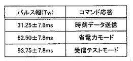
すなわち、図2に示すように、外部機器20から時刻データ供給装置1へのコマンドを表わす単一パルス信号のパルス幅Twが、512Hzのクロック信号の1周期(約1,9531μ秒)のほぼ整数倍に設定されていて、制御回路3がそのパルス幅Twの長短を測定することで外部機器20からのコマンドの意味を解釈する。図2に示すように、外部機器20から時刻データ供給装置1へ送られるコマンドを表わす単一パルス信号のパルス幅Twは、31.25±7.8m秒、62.50±7.8m秒、及び93.75±7.8m秒に設定されていて、それぞれのコマンドのパルス幅Twは、時刻データ供給装置1から外部機器20への時刻データ送信要求、時刻データ供給装置1が定期的に標準電波を受信して時刻修正する動作を行なわずに消費電流を押さえるための省電力モード移行命令、及び製造工程において時刻データ供給装置1の受信機能を検査するための受信テストモード移行命令を意味している。このパルス幅Twは、512Hzのクロック信号の1周期(約1,9531μ秒)のほぼ16倍、32倍及び48倍に設定されていて、制御回路3が常時動作している第1の発振回路6から分周された512Hzのクロック信号のみにより容易にコマンドのパルス幅を測定してそのコマンドの意味を解釈して対応できる様になっている。
【0035】
再び図1を参照すると、制御回路3はレジスタ5の内部時刻が、例えば、2時、5時、8時…などの所定時刻になると、受信回路4を動作状態にして長波標準電波を受信して図5に示すような標準時刻コードを得、そして受信回路4からの標準時刻コード信号をデコード処理して標準時刻を得ると共にレジスタ5内の内部時刻を修正する。上記のように、時刻データ供給装置1と外部機器20の間は、2本の通信線で結ばれていてシリアル送受信を行なう。この通信線により外部機器20の送信データ端子SDは時刻データ供給装置1の受信データ端子RDと、外部機器20の受信データ端子RDは時刻データ供給装置1の送信データ端子SDとそれぞれ接続されている。図1中の10aおよび10bはそれぞれ時刻データ供給装置1の送信バッファ、受信バッファである。
【0036】
時刻データ供給装置1はさらに、時刻データ供給装置1の図示しない電源電池の電力消耗を防止するため、必要な時(外部機器20に時刻データをシリアル送信で供給する時)にのみ第1の発振回路6よりも高い周波数で発振動作する、すなわち、適時発振動作する、第2の発振回路8を有する。この第2の発振回路8は、4.92MHzの周波数で発振する水晶振動子に比べて安価なセラミック振動子を有している。これは第2の発振回路8は常時発振動作してレジスタ5に内部時計の時刻データを与える計時機能を行なう第1の発振回路6よりは精度が要求されないからである。第2の発振回路8は発振が開始されて動作が安定すると第2の分周回路9を経由して、1200Hzと19200Hzのクロック信号を制御回路3に供給する。第2の発振回路8の動作の安定には数m秒を要し、コマンドデータが送信されてから発振開始した場合には発振動作直後の数ビットは正常に読み取ることができない。このために従来技術では外部機器からダミーデータを送信して高速発振を安定させた後、コマンドデータを送信するという手法がとられていた。
【0037】
図1に示す本実施の形態の制御回路3に供給される分周された1200Hzのクロック信号は、時刻供給データ装置1が外部機器20へ時刻データ信号を2進値データとしてシリアル送信する際、通信ビットレートを1200bps(ビット/秒)とした場合に制御回路3が必要とするものである。なお、詳しく述べないが、本例の時刻供給データ装置1は、従来の外部機器にも対応できるように単一のパルス幅によるコマンドの受信の他、図示しないスイッチの選択によって従来のシリアルデータによる各種コマンド又はデータの受信ができるものとする。19200Hzのクロック信号は、このシリアルデータの受信時に制御回路3が必要とするものである。通常調歩同期式では送信時の通信ビットレートの16倍、すなわち、1200bpsの16倍の19200Hzで、サンプリングを行なって受信データの2進値化をするために、19200Hzのクロック信号が使用される。なお、この選択制御のために本例の単一のパルス幅によるコマンドを用いても良い。
【0038】
従って、時刻データを2進値化して時刻データ供給装置1から外部機器20へ送る際のシリアル送信の通信ビットレートに依存して、この第2の分周回路9が出力するクロック信号周波数及び第2の発振回路8の発振周波数は、第1の分周回路7が出力するクロック周波数及び第1の発振回路6の発振周波数と異なるものが使用される。しかし、時刻データ供給装置1から外部機器20へ時刻データを高速(短時間)でシリアル送信するため、第2の発振回路8は第1の発振回路6よりも高い周波数で発振して制御回路3にクロック周波数を供給する。しかし、時刻データの送信時以外は、第2の発振回路8からの分周された1200Hzと19200Hzのクロック信号は必要でない。このため、余分な電力消費を防ぐために、本実施の形態の時刻データ供給装置1では、外部機器20から時刻データ送信要求を表わすパルス幅Tw=31.25±7.8m秒の単一のパルスのコマンドを受信した後で、第2の発振回路8の発振動作を開始してその発振動作が安定した後で2進値化した時刻データを外部機器20へシリアル送信し、その後に第2の発振回路8の発振動作を停止するという適時動作を行なう。
【0039】
次に図3を図1と併せて参照して、本発明の1つの実施の形態による外部機器2が時刻データを時刻データ供給装置1から獲得する手順を説明する。図3は、本発明による1つの実施の形態による時刻データのシリアル送受信のタイミングチャートを示す。
【0040】
本発明の実施の形態による時刻データ供給装置1は、待機状態においては第1の発振回路6のみが常時発振動作をしていて、制御回路3が第1の分周回路7から供給される512Hzの間隔で受信データ端子RDの状態をサンプリングしている。外部機器20から図3のRDに示すような単一のパルス(パルス幅Tw=31.25±7.8m秒)が送信されると、制御回路3はそのパルス幅を測定する。測定したパルス幅Twが所定の範囲内(31.25±7.8m秒)であった場合、制御回路3は第2の発振回路8を動作させて4.92MHzの発振を開始し、パルス幅に応じて時刻データのシリアル送信処理を行い(図3のSD)、そして送信処理後に第2の発振回路8の動作を停止する。
【0041】
時刻データ供給装置1が外部機器20に送信する時刻データは、レジスタ5に記憶されている内部時刻データであり、所定のフォーマットで時刻データ供給装置の送信データ端子SDからシリアル送信される。この所定のフォーマットには、年・月・日・時・分・秒・曜日・うるう秒に関する情報・夏時間に関する情報・時刻データの鮮度または確度・局情報・動作モード・チェックサムなどが含まれている。時刻データの最小時刻単位は秒データであるので、外部機器20との秒タイミングの同期をとるために、送信データの最終ビットが時刻データ供給装置1の内部の秒と一致する様にタイミングを調整して出力する。
【0042】
本発明では、外部装置20から時刻データ供給装置1へのコマンド送信は、単一のパルスで行なわれるためノイズの発生は比較的少なく、従来のパルス列のコマンド送信よりも、受信回路4の標準電波受信操作に妨害を与えるおそれはない。しかし、時刻データ供給装置1が外部機器20に時刻データをシリアル送信する際、2進値化された時刻データのパルス列がノイズ発生の原因となって、受信回路4の標準電波受信操作に妨害を与えるおそれがある。このため、時刻データ供給装置1が外部機器20に時刻データをシリアル送信するタイミングは、受信回路4が標準電波を受信している際にノイズの影響を最小にできる時間を選ぶことができる。図5を参照すると、標準電波のタイムコード中、例えば、毎分4秒、毎分10秒〜11秒、毎分20秒〜21秒等の時間帯には、800m秒の矩形波信号が固定的に送信されていて標準時刻情報には直接関係が無い。従って、この時間帯を選んで外部機器20に時刻データをシリアル送信すると、受信回路4が標準電波を受信している際の受信操作に対する影響を最小にできる。さらに、時刻データ供給装置1の制御回路3が、時刻データを外部機器20に送信した後、数秒間は受信回路4によるタイムコードを読み込まないようにすればノイズの影響をさらに少なくすることができる。
【0043】
もし、外部機器20から時刻データ供給装置1の受信データ端子RDへ省電力モード移行命令を表わすパルス幅(Tw=62.50±7.8m秒)の単一のパルスのコマンドが送られると、そのコマンドに応じて標準電波の定期受信動作を行なわず消費電流を抑える。もし、外部機器20から時刻データ供給装置1の受信データ端子RDへ受信テストモード移行命令を表わすパルス幅(Tw=93.75±7.8m秒)の単一のパルスのコマンドが送られると、そのコマンドに応じて標準電波の受信テストのため、受信回路4を動作させて標準電波の受信の可否を判定して外部機器20にテスト結果を送信する。もし、図3のRDが所定のパルス幅(Tw=31.25±7.8m秒、62.50±7.8m秒、及び93.75±7.8m秒)以外の場合はノイズとみなして無視して待機状態の計時動作を継続する。この待機状態中、時刻データ供給装置1は上述したように受信回路4により定期的に標準電波を受信して第1の発振回路6による内部時刻を修正する。
【0044】
次に、図4を参照して本発明の1つの実施の形態による単一パルスのパルス幅Twの測定の手順を説明する。制御回路3は第1の分周回路7から供給される512Hz、即ち、約1.95m秒の間隔で受信データ端子RD上の信号をサンプリングしている。突発的なノイズによる誤動作を防ぐため、制御回路3は図4に示す様にサンプリングした値の変化が2回連続した場合にのみ、受信データ端子RD上の信号の電圧変化があったとみなしている。従って、図4に示すように、制御回路3は、図4上のRDとして示す受信データ端子RD上の信号(パルス幅Tw’)に対しては、図4下のサンプリング結果を生じ、制御回路3はこのサンプリング結果のパルス幅Twを測定する。この結果、受信データ端子RD上の信号に所定時間未満(2サンプリング時間未満=約3.9m秒)の変化があった場合は、制御回路3は無視する。これにより、突発的なノイズにより誤動作を防止している。
【0045】
外部機器20は、コマンドの機能に応じて図2に示すパルス幅の単一のパルスを一回発生すれば良い。しかし、RS−232Cなどの調歩同期式の通信ポートを内蔵しているコンピュータ等を使用する場合は通信ポートを用いてデータを送信したほうが制御が容易になる場合がある。例えば、RS−232Cではビットレート1200bps、データ長7ビット、ストップビット数1、パリティビット無しとした場合、フレーム長は9ビット、即ち7.5m秒となるので、4バイトのNullコード(00h)を4回連続して送信すれば、図5に示すようにNullコードのパルス列は全体として30m秒(Tw’)となり、等価的に単一のパルスTwとみなされ、時刻データ送信コマンドと認識される。同様に8バイト、12バイトのNullコードを送信すれば各々省電力モード、受信テストモードコマンドとみなされる。RS−232Cでは連続してNullコードを送信するとストップビットのために周期的にレベルが反転するが、ビット幅は約0.83m秒であり、上述した本実施の形態によれば所定時間未満のパルス幅のノイズとみなされるので正しいコマンドとして認識可能となる。
【0046】
次に、時刻データ供給装置1のリセット後の初期状態における動作について述べる。リセット後、制御回路3はまず受信回路4による標準電波の受信を開始する。標準電波の受信動作は秒同期、次にマーカーの取得、次にタイムコードの取得の順番に行われ、各ステップで正常なデータが得られない場合は所定の時間でタイムアウトして最初から受信動作を行なう。また、データの信頼性を高めるため複数フレーム(1フレーム=60秒間)のデータを比較している。このため標準時刻情報を得るのには、早い場合でも4〜5分、遅い場合には数十分以上かかる場合がある。制御回路3は通常の待機状態では外部機器20からの時刻データ送信コマンドによってのみ時刻データを外部機器20へ送信するが、リセット後の初期における標準電波の受信により正しい時刻データを取得した時に一度だけ自動的に時刻データを外部機器20へ送信する。外部機器20は時刻データが時刻データ供給装置1から送信される事により、時刻データ供給装置1が時刻データを受信したことを知る事ができるので、時刻データが送信されるのを待っているだけでよく初期の制御処理が簡易となる。
【0047】
なお、時刻データ供給装置1の受信回路4が受信する時刻ソースとしては、標準電波以外にGPS、テレフォンJJY、アナログ放送電波、デジタル放送電波などを利用してもよい。
【0048】
なお、時刻データ供給装置1の受信回路4が標準電波受信中に外部機器20からコマンドが送られてきた場合の対処方法として、コマンドを受け付けないようにする、また受信動作を中断または中止してコマンド処理後に受信を再開するなどの方法も考えられる。
【0049】
【発明の効果】
本発明によれば、低消費電流が求められる時刻データ供給装置に於いて、外部(ホスト)機器側が時刻データを求める際に、一度ダミーデータを送信して時刻データ供給装置を待機状態から高速処理に切り換えた後、再度時刻データ送信要求を送るという余分な処理が不要となり、かつ簡単な処理で複数のコマンドを識別する事が可能となる。
【0050】
また、コマンドのパルス幅(Tw)の測定を行なう際に、所定時間以下のレベルの変化を受け付けないようにしたので、外部(ホスト)機器側ではタイマー等により簡易に所定のパルス幅のパルスを発生する方法と、従来のRS−232Cなどストップビットを有する調歩同期式の送信データにより所定のパルスを発生する方法の何れでもコマンドを送信することが可能であるので、外部(ホスト)機器の設計自由度が広がる。
【0051】
また、リセット後の初期の標準電波の受信終了と共に自動的に時刻データを時刻データ供給装置から外部(ホスト)機器へ送信するようにしたので、外部(ホスト)機器側は時刻データが送られてくるのを待っていればよく、外部(ホスト)機器側の制御処理が簡易なる。更に時刻データ送信要求が頻繁に送信される事によりデータ線からノイズが発生して受信所要時間が必要以上に長くなるという不具合が無くなる。
【0052】
また、標準電波の定期自動受信の最中に外部(ホスト)機器が時刻データ送信要求を送信しても、パルス列では無いのでノイズの発生量を低減できる。
【図面の簡単な説明】
【図1】本発明の1つの実施の形態による時刻データ供給装置の要部の構成を示すブロック図。
【図2】本発明の単一パルスのパルス幅の長短によるコマンドの意味の違いを示す表。
【図3】本発明の1つの実施の形態による時刻データのシリアル送受信のタイミングチャート。
【図4】本発明の1つの実施の形態による単一パルスのパルス幅Twの測定方法を示すタイミングチャート。
【図5】長波標準電波により送信される標準時刻コードを示す矩形波信号のタイムコード。
【図6】本発明の1つの実施の形態によるRS−232Cにより等価的に実現される単一パルスのパルス幅Twの測定方法を示すタイミングチャート。
【符号の説明】
1 時刻データ供給装置
3 制御回路
4 受信回路
5 レジスタ
6 第1の発振回路
7 第1の分周回路
8 第2の発振回路
9 第2の分周回路
10a 送信バッファ
10b 受信バッフア
20 外部(ホスト)機器
RD 受信データ端子
SD 送信データ端子[0001]
BACKGROUND OF THE INVENTION
The present invention relates to a time data supply device and a time data supply method for receiving accurate time data based on a long wave standard radio wave or the like and transmitting it by serial communication in response to a request from an external device.
[0002]
[Prior art]
In recent years, the output of long-wave standard radio waves has been increased, and the number of transmission stations has been increased, making it possible to obtain accurate time information relatively easily throughout the country. In recent years, there have been an increasing number of scenes where accurate time information is required in many home appliances, OA devices, information processing apparatuses, or timed management facilities.
[0003]
On the other hand, a complex algorithm is required to receive the time information of the standard radio wave without error and with an appropriate reception time. For this reason, the number of cases in which the receiving circuit and the data processing unit are combined into a time data supply device is increasing.
[0004]
Conventionally, in such a time data supply device, a standard time signal is periodically received to correct the internal clock, and a time data request command is received from an external device such as a home appliance, OA device, information processing device, or time management facility. There is one that outputs time data by serial communication. Such a time data supply apparatus may have a plurality of operation modes. The operation mode can be set by receiving a plurality of commands from an external device.
[0005]
As a communication method for outputting time data by serial communication, an asynchronous method or a synchronous method is widely used.
[0006]
In the case of synchronous two-way communication, at least three communication lines of a transmission data line, a reception data line, and a synchronous clock are required. In the asynchronous system disclosed in
[0007]
For this reason, a time data supply device using a dry battery or a solar battery that requires low current consumption performs a timekeeping operation at a low-speed oscillation such as 32.768 kHz during standby, and switches to a high-speed operation when transmitting / receiving serial data. A technique is used to suppress the overall average current consumption.
[0008]
[Patent Document 1]
JP 2000-196700 (paragraph [0061])
[0009]
[Problems to be solved by the invention]
However, when the conventional method as described above is used, high-speed oscillation is started by using the voltage change of the data line as a trigger in the low-speed oscillation standby state, but it takes some time until the high-speed oscillation is stably started. As a result, there was a problem that the leading data was missing bits. As a solution to this, after sending dummy data once from an external device that is a host device and switching the time data supply device on the receiving side to high speed operation, a time data request command is sent from the external device that is the host device to the time on the receiving side. There is also a method of transmitting to the data supply device, but in this case, extra processing is required until time data is obtained.
[0010]
As another problem, when serial data is transmitted / received during the reception operation of the standard radio wave, noise generated from the data line adversely affects the reception of the standard radio wave of the time data supply device.
[0011]
Furthermore, as another problem, during the standard radio wave reception operation after resetting the time data supply device, the time data is transmitted in response to the time data request command from the host device (external device), and the time data in the time data is When the host device (external device) detects that the standard radio wave has not yet been successfully received based on the freshness information, it waits for several minutes and then repeats the operation of sending the time data request command. When the time data request command is transmitted, there is a case in which a vicious circle occurs in which the time data supply device has a longer reception time of the standard radio wave due to the influence of noise.
[0012]
[Means for Solving the Problems]
In order to solve the above-described problem, in the present invention, simply speaking, when the time data supply device receives a command from an external device, it does not receive and process a signal binarized by digital processing, but a pulse. A single signal that can identify the meaning of the command according to the length of the width is received and processed. Measurement of the pulse width of a single signal is possible even when the time data supply device operates at low speed, and the meaning of the command represented by the length of the pulse width of the single signal from an external device is identified. After that, it switches to high-speed oscillation and transmits time data to an external device.
[0013]
In order to solve the problem that the time data transmission / reception operation becomes longer than necessary when the time data transmission request is frequently sent from the external device in the initial operation such as resetting the time data supply device, etc. In the initial operation such as reset, the time data supply device automatically transmits the latest updated time data to the external device even if there is no time data transmission request from the external device.
[0014]
That is, according to the first aspect of the present invention, there is provided a first clock circuit that has a first oscillation circuit that operates at all times and performs a clock operation by dividing the output from the first oscillation circuit. Driven by the second oscillation circuit, the second oscillation circuit that operates at a time that oscillates at a higher frequency than the above circuit, time correction means that receives a signal including time information and corrects the time of the time measuring means, and the second oscillation circuit. Serial transmission means for supplying time data of the time measuring means to the external device by serial transmission in response to a command from the external device, and time in response to the command represented by a single pulse sent from the external device. A time data supply device is provided that includes means for starting the operation of the second oscillation circuit for serially transmitting data.
[0015]
According to the time data supply device of the present invention of
[0016]
According to the second aspect of the present invention, in the time data supply device according to the first aspect, the single pulse has a pulse width of a different length, and the length of the pulse width depends on the length of the pulse width. There is provided a time data supply device further comprising means for identifying a plurality of meanings of a command, and performing control according to the meaning of the command.
[0017]
According to the time data supply device of the second aspect of the present invention, it is possible to control the time data supply device in addition to the time data transmission request from the external device. For example, a single pulse signal having a different pulse width is transmitted from the external device to the time data supply device, and the time data supply device is set to the power saving mode to prevent power consumption of the power supply battery or the like. Alternatively, the time data supply device can be set to the reception test mode to test the quality of the radio wave reception state that informs the standard time information received by the time adjustment means and notify the external device.
[0018]
According to the third aspect of the present invention, in the time data supply device according to the first or second aspect, when measuring the pulse width of the single pulse, the change of the pulse for less than a predetermined time is ignored. A time data supply device is provided.
[0019]
According to the time data supply apparatus of the present invention of
[0020]
According to the fourth aspect of the present invention, in the time data supply device according to any one of the first to third aspects, the pulse width of the single pulse is an output from the first oscillation circuit. A time data supply device is provided which is approximately equal to an integer multiple of the divided period.
[0021]
According to the time data supply device of the present invention described in
[0022]
According to the fifth aspect of the present invention, in the time data supply device according to any one of the first to fourth aspects, the pulse width of the single pulse is within a predetermined range. A time data supply device for starting the operation of the second oscillation circuit is provided.
[0023]
According to the present invention described in
[0024]
According to the sixth aspect of the present invention, a time measuring unit that generates time data, a time correcting unit that receives a signal including time information and corrects the time of the time measuring unit, and a command from an external device In response, serial transmission means for supplying the time data of the timekeeping means to the external device by serial transmission, and after the time correction means corrects the time data of the timekeeping means at the time of resetting, the corrected time data is transferred to the external device. And a time data supply apparatus including means for automatically transmitting the data by serial transmission means.
[0025]
According to the time data supply device of the present invention of claim 6, at the time of resetting, the time data supply device automatically updates the latest time data that has been updated even if there is no time data transmission request from the external device. When the time data transmission request is frequently sent from an external device at the time of resetting the time data supply device, the problem that the time data transmission / reception operation becomes longer than necessary is solved.
[0026]
According to the seventh aspect of the present invention, in the time data supply device according to any one of the first to sixth aspects, the time correction unit transmits the time data to the external device by the serial transmission unit. There is provided a time data supply device characterized in that it is performed at a timing that has the least influence on reception of a signal including time information.
[0027]
According to the time data supply device of the present invention of claim 7, the transmission of the time data to the external device by the serial transmission means is relatively important in the standard time code of 60 seconds per frame included in the long wave standard radio wave. When the serial data is transmitted / received during the standard radio wave reception operation, the time data is supplied by the noise generated from the data line. The problem of adversely affecting the reception of the standard radio wave of the device can be reduced.
[0028]
According to the present invention as set forth in
[0029]
According to the method of
[0030]
According to the present invention as set forth in
[0031]
According to the method of
[0032]
DETAILED DESCRIPTION OF THE INVENTION
DESCRIPTION OF EXEMPLARY EMBODIMENTS Hereinafter, exemplary embodiments of the invention will be described in detail with reference to the accompanying drawings. FIG. 1 is a block diagram showing a configuration of a main part of a time
[0033]
The time
[0034]
That is, as shown in FIG. 2, the pulse width Tw of a single pulse signal representing a command from the
[0035]
Referring to FIG. 1 again, when the internal time of the
[0036]
Further, the time
[0037]
The frequency-divided 1200 Hz clock signal supplied to the
[0038]
Therefore, depending on the communication bit rate of serial transmission when the time data is binarized and sent from the time
[0039]
Next, with reference to FIG. 3 in conjunction with FIG. 1, a procedure in which the
[0040]
In the time
[0041]
The time data transmitted from the time
[0042]
In the present invention, since the command transmission from the
[0043]
If a command of a single pulse having a pulse width (Tw = 62.50 ± 7.8 msec) representing a power saving mode transition command is sent from the
[0044]
Next, a procedure for measuring the pulse width Tw of a single pulse according to one embodiment of the present invention will be described with reference to FIG. The
[0045]
The
[0046]
Next, the operation of the time
[0047]
Note that as a time source received by the receiving
[0048]
Note that, as a coping method when a command is sent from the
[0049]
【The invention's effect】
According to the present invention, in a time data supply device that requires low current consumption, when the external (host) device obtains time data, dummy data is transmitted once and the time data supply device is processed at high speed from a standby state. After switching to, an extra process of sending a time data transmission request again becomes unnecessary, and a plurality of commands can be identified by a simple process.
[0050]
In addition, when measuring the pulse width (Tw) of the command, the change of the level less than the predetermined time is not accepted, so the external (host) device side can easily apply a pulse with the predetermined pulse width by a timer or the like. The command can be transmitted by either the method of generating or the method of generating a predetermined pulse by the asynchronous transmission data having stop bits such as the conventional RS-232C. Increases freedom.
[0051]
In addition, since the time data is automatically transmitted from the time data supply device to the external (host) device when the reception of the initial standard radio wave after the reset is completed, the time data is sent from the external (host) device side. It is only necessary to wait for it to come, and the control processing on the external (host) device side is simplified. Furthermore, since the time data transmission request is frequently transmitted, noise is generated from the data line, and there is no problem that the time required for reception becomes longer than necessary.
[0052]
Further, even if an external (host) device transmits a time data transmission request during regular automatic reception of a standard radio wave, the amount of noise generated can be reduced because it is not a pulse train.
[Brief description of the drawings]
FIG. 1 is a block diagram showing a configuration of a main part of a time data supply device according to an embodiment of the present invention.
FIG. 2 is a table showing the difference in command meaning depending on the pulse width of a single pulse according to the present invention.
FIG. 3 is a timing chart of serial transmission / reception of time data according to one embodiment of the present invention.
FIG. 4 is a timing chart showing a method for measuring a pulse width Tw of a single pulse according to one embodiment of the present invention.
FIG. 5 is a time code of a rectangular wave signal indicating a standard time code transmitted by a long wave standard radio wave.
FIG. 6 is a timing chart showing a method for measuring a pulse width Tw of a single pulse that is equivalently realized by RS-232C according to one embodiment of the present invention.
[Explanation of symbols]
1 Time data supply device
3 Control circuit
4 Receiver circuit
5 registers
6 First oscillation circuit
7 First frequency divider
8 Second oscillator circuit
9 Second frequency divider
10a Transmission buffer
10b Receive buffer
20 External (host) equipment
RD reception data terminal
SD transmission data terminal
Claims (9)
上記第1の発振回路よりも高い周波数で発振する適時動作する第2の発振回路と、
上記第1の発振回路からのクロック信号に基づき単一のパルスからなるコマンドを識別する手段と、
時刻情報を含む信号を受信して上記計時手段の時刻を修正する時刻修正手段と、
上記第2の発振回路により駆動されて外部機器からの上記コマンドに応じて上記計時手段の時刻データをシリアル送信で上記外部機器へ供給するシリアル送信手段と、
外部機器から送られる上記単一のパルスで表わされる上記コマンドに応答して時刻データをシリアル送信するため上記第2の発振回路の動作を開始させる手段とを含む時刻データ供給装置。Clocking means that has a first oscillation circuit that operates constantly and divides the output from the first oscillation circuit to perform a clocking operation;
A second oscillation circuit that operates in a timely manner and oscillates at a higher frequency than the first oscillation circuit;
Means for identifying a command comprising a single pulse based on the clock signal from the first oscillation circuit;
Time correction means for receiving a signal including time information and correcting the time of the time measuring means;
And serial transmission means for supplying to the external device the time data of the time counting means in serial transmission in accordance with the command from the external device is driven by the second oscillator circuit,
Time data feed and means for starting the operation of the second oscillator circuit for the time data in response to the command represented by the single pulses sent from an external device to serial transmission.
常時動作する第1の発振回路を有し当該第1の発振回路からの出力を分周して計時動作を行なう計時手段を備え、
上記第1の回路よりも高い周波数で発振する適時動作する第2の発振回路を備え、
時刻情報を含む信号を受信して上記計時手段の時刻を修正する時刻修正手段を備え、
上記第1の発振回路からのクロック信号に基づき単一のパルスからなるコマンドを識別する手段を備え、
上記第2の発振回路により駆動されて外部機器からの上記コマンドに応じて上記計時手段の時刻データをシリアル送信で上記外部機器へ供給するシリアル送信手段を備え、
上記外部機器から送られる上記単一のパルスで表わされる上記コマンドに応答して時刻データをシリアル送信するため上記第2の発振回路の動作を開始させること、
を含むことを特徴とする時刻データ供給装置から時刻データを外部機器に供給する方法。A method of supplying time data to an external device from a time data supply device,
A time-counting unit that has a first oscillation circuit that always operates and divides an output from the first oscillation circuit to perform a time-measurement operation;
A second oscillation circuit that operates in a timely manner and oscillates at a higher frequency than the first circuit;
Time correction means for receiving a signal including time information and correcting the time of the time measuring means,
Means for identifying a command comprising a single pulse based on the clock signal from the first oscillation circuit;
In accordance with the command from the external device is driven by the second oscillator circuit includes a serial transmission unit for supplying time data of the time counting means to said external device by serial transmission,
To initiate the operation of the second oscillator circuit for responding to serial transmission time data to the command represented by the single pulses sent from the external device,
Method for providing time data to the external device from the time data supply apparatus which comprises a.
を含むことを特徴とする請求項8に記載の時刻データ供給装置から時刻データを外部機器に供給する方法。After the time adjustment means modifies the time data of the clock means during reset, to automatically send the time data through the serial transmission unit to the external device,
The method of supplying time data from the time data supply apparatus according to claim 8 to an external device.
Priority Applications (1)
| Application Number | Priority Date | Filing Date | Title |
|---|---|---|---|
| JP2003120948A JP4255307B2 (en) | 2003-04-25 | 2003-04-25 | Time data supply apparatus and time data supply method |
Applications Claiming Priority (1)
| Application Number | Priority Date | Filing Date | Title |
|---|---|---|---|
| JP2003120948A JP4255307B2 (en) | 2003-04-25 | 2003-04-25 | Time data supply apparatus and time data supply method |
Publications (2)
| Publication Number | Publication Date |
|---|---|
| JP2004325278A JP2004325278A (en) | 2004-11-18 |
| JP4255307B2 true JP4255307B2 (en) | 2009-04-15 |
Family
ID=33499642
Family Applications (1)
| Application Number | Title | Priority Date | Filing Date |
|---|---|---|---|
| JP2003120948A Expired - Fee Related JP4255307B2 (en) | 2003-04-25 | 2003-04-25 | Time data supply apparatus and time data supply method |
Country Status (1)
| Country | Link |
|---|---|
| JP (1) | JP4255307B2 (en) |
Cited By (3)
| Publication number | Priority date | Publication date | Assignee | Title |
|---|---|---|---|---|
| US7687007B2 (en) | 2002-06-20 | 2010-03-30 | Obducat Ab | Mold for nano imprinting |
| US7758794B2 (en) | 2001-10-29 | 2010-07-20 | Princeton University | Method of making an article comprising nanoscale patterns with reduced edge roughness |
| CN101970198B (en) * | 2008-03-19 | 2013-05-29 | 柯尼卡美能达精密光学株式会社 | Method for producing wafer lens |
Families Citing this family (2)
| Publication number | Priority date | Publication date | Assignee | Title |
|---|---|---|---|---|
| CN100476640C (en) * | 2003-12-24 | 2009-04-08 | 西铁城控股株式会社 | Radio controlled clock, electronic device and time correction method |
| JP5353117B2 (en) * | 2008-08-25 | 2013-11-27 | セイコーエプソン株式会社 | Standard radio wave receiving device, radio wave correction watch and standard radio wave receiving method |
-
2003
- 2003-04-25 JP JP2003120948A patent/JP4255307B2/en not_active Expired - Fee Related
Cited By (3)
| Publication number | Priority date | Publication date | Assignee | Title |
|---|---|---|---|---|
| US7758794B2 (en) | 2001-10-29 | 2010-07-20 | Princeton University | Method of making an article comprising nanoscale patterns with reduced edge roughness |
| US7687007B2 (en) | 2002-06-20 | 2010-03-30 | Obducat Ab | Mold for nano imprinting |
| CN101970198B (en) * | 2008-03-19 | 2013-05-29 | 柯尼卡美能达精密光学株式会社 | Method for producing wafer lens |
Also Published As
| Publication number | Publication date |
|---|---|
| JP2004325278A (en) | 2004-11-18 |
Similar Documents
| Publication | Publication Date | Title |
|---|---|---|
| KR100902601B1 (en) | Wireless Time System And Method for Synchronizing Time | |
| JP4164662B2 (en) | Portable terminal and GPS time keeping method | |
| US5859595A (en) | System for providing paging receivers with accurate time of day information | |
| US5663715A (en) | Synchronized paging system | |
| US7027363B2 (en) | Time measurement system and method of controlling the same | |
| JPWO2005062137A1 (en) | Radio correction clock, electronic device and time correction method | |
| EP1395072B1 (en) | Radio communication apparatus and its reception timing estimating method | |
| JP4255307B2 (en) | Time data supply apparatus and time data supply method | |
| JP2001051077A (en) | Information output device for correcting time and automatic time correcting clock | |
| JP2002296374A (en) | Time information acquiring method and device and radio- controlled timepiece | |
| JP5127342B2 (en) | Receiving apparatus and method | |
| JP2897684B2 (en) | Wireless transceiver | |
| JP2003134098A (en) | Serial receiver | |
| JP2004023350A (en) | Base station, communication method, communication program, and computer-readable recording medium stored with the communication program | |
| JP2006258475A (en) | Radio controlled clock | |
| JP4633556B2 (en) | Time recording device | |
| JP2000019262A (en) | Method and system for observing amount of rain of synchronous type self-activation system | |
| JP2002286877A (en) | Method and apparatus of deciding start timing of time frame, time information detector and radio-controlled clock | |
| JP2020088624A (en) | Electronic apparatus | |
| JP7375447B2 (en) | How to adjust the time of a radio-controlled watch and a radio-controlled watch | |
| JPH10257004A (en) | Communication equipment | |
| JP2004144688A (en) | Method and apparatus for acquiring time information, and radio controlled clock | |
| JP2002214372A (en) | Time control device and clock | |
| JP3837093B2 (en) | Alarm clock with radio wave correction function | |
| US20220125011A1 (en) | Electronic animal identification tag reader synchronisation |
Legal Events
| Date | Code | Title | Description |
|---|---|---|---|
| A621 | Written request for application examination |
Free format text: JAPANESE INTERMEDIATE CODE: A621 Effective date: 20051006 |
|
| A977 | Report on retrieval |
Free format text: JAPANESE INTERMEDIATE CODE: A971007 Effective date: 20080911 |
|
| A131 | Notification of reasons for refusal |
Free format text: JAPANESE INTERMEDIATE CODE: A131 Effective date: 20080916 |
|
| A521 | Written amendment |
Free format text: JAPANESE INTERMEDIATE CODE: A523 Effective date: 20081020 |
|
| TRDD | Decision of grant or rejection written | ||
| A01 | Written decision to grant a patent or to grant a registration (utility model) |
Free format text: JAPANESE INTERMEDIATE CODE: A01 Effective date: 20090113 |
|
| A01 | Written decision to grant a patent or to grant a registration (utility model) |
Free format text: JAPANESE INTERMEDIATE CODE: A01 |
|
| A61 | First payment of annual fees (during grant procedure) |
Free format text: JAPANESE INTERMEDIATE CODE: A61 Effective date: 20090127 |
|
| FPAY | Renewal fee payment (prs date is renewal date of database) |
Free format text: PAYMENT UNTIL: 20120206 Year of fee payment: 3 |
|
| R150 | Certificate of patent (=grant) or registration of utility model |
Free format text: JAPANESE INTERMEDIATE CODE: R150 |
|
| LAPS | Cancellation because of no payment of annual fees |