JP4250806B2 - Field frequency conversion device and conversion method - Google Patents
Field frequency conversion device and conversion method Download PDFInfo
- Publication number
- JP4250806B2 JP4250806B2 JP12729299A JP12729299A JP4250806B2 JP 4250806 B2 JP4250806 B2 JP 4250806B2 JP 12729299 A JP12729299 A JP 12729299A JP 12729299 A JP12729299 A JP 12729299A JP 4250806 B2 JP4250806 B2 JP 4250806B2
- Authority
- JP
- Japan
- Prior art keywords
- class
- motion
- image
- field
- determining
- Prior art date
- Legal status (The legal status is an assumption and is not a legal conclusion. Google has not performed a legal analysis and makes no representation as to the accuracy of the status listed.)
- Expired - Fee Related
Links
Images


Description
【0001】
【発明の属する技術分野】
この発明は、入力画像に対して例えば解像度の向上等を目的とする画像情報変換を施すフィールド周波数変換装置および変換方法に関する。
【0002】
【従来の技術】
フィールド周波数を例えば50Hzから60Hzに変換するフィールド周波数変換の方法として、フィールド間の動きを推定し、推定した動き量を用いてフィールド間に新しいフィールドを生成する処理が知られている。しかし、かかる方法においては、動き推定に失敗すると、処理結果に直接影響するという問題があった。また、かかる方法は、単なる補間処理であり、時間的または空間的な解像度を向上させることはできない。
【0003】
また、本願出願人は、元の画像中の複数個のフィールドから抽出した画像データを使用して、クラス分類適応処理によって新たなフィールドを生成することにより、フィールド周波数を例えば50Hzから100Hzに変換する変換する方法を先に提案している。ここで、クラス分類適応処理は以下のような処理である。すなわち、入力画像から所定の範囲の画像データを切り出し、切り出した画像データのレベル分布を検出し、検出結果に基づいてクラス分類を行う。そして、分類されたクラス毎に予め決定されている予測係数と、入力画像から別途を切り出した所定範囲の画像データとに基づく演算の結果として例えばフィールド倍速化画像等の出力画像を得る。ここで、予測係数は、出力画像と同一の信号形式を有する画像(教師画像と称される)と、入力画像と同一の信号形式を有する画像(生徒画像と称される)とに基づく演算処理によって決定される。
【0004】
【発明が解決しようとする課題】
しかし、このような方法では、入力画像の動き量が抽出される画像データの範囲より大きい場合には、的確なクラス分類適応処理を行うことができないので、正しいフィールドを生成することができない。
【0005】
従って、この発明の目的は、特に入力画像の動き量が大きい場合等において、フィールド周波数変換をより的確に行うことが可能なフィールド周波数変換装置および変換方法を提供することにある。
【0006】
【課題を解決するための手段】
請求項1の発明は、入力画像のフィールド間に新たなフィールドを生成することによって
入力画像のフィールド数より多いフィールド数の出力画像を形成するフィールド周波
数変換装置において、
入力画像の処理の対象である注目画素の動きベクトルを検出する動き量推定手段と、
動きベクトルによって、入力画像に対する動き補償処理を行う動き補償手段と、
動きベクトルの値の大きさによって、動きクラスを決定する動きクラス決定手段と、
動き補償手段の出力から、注目画素の周辺の複数の画像データを切り出す第1の画像切り出し手段と、
第1の画像切り出し手段によって切り出される複数の画像データのレベル分布を検出し、検出したレベル分布に基づいて空間クラスを決定する空間クラス決定手段と、
動きクラス決定手段からの動きクラスと、空間クラス決定手段からの空間クラスとを合成してクラスを決定するクラス決定手段と、
動き補償手段の出力から、注目画素の周辺の複数の画像データを切り出す第2の画像切り出し手段と、
クラスのそれぞれに対応して予め決定され、出力画像信号を推定するための予測係数を記憶し、記憶している予測係数の内から、クラス決定手段からのクラスに対応するものを出力する係数記憶手段と、
第2の画像切り出し手段によって切り出される複数の画像データと、係数記憶手段から供給される予測係数との積和演算を行い、上記出力画像の画像データの予測値を生成する演算処理手段とを有し、
予測係数は、積和演算によって、出力画像信号の画素を生成した時に、生成された値と画素の真値との誤差を最小にするように、クラス毎に予め学習によって求められて係数記憶手段に記憶される
ことを特徴とするフィールド周波数変換装置である。
【0007】
請求項5の発明は、入力画像のフィールド間に新たなフィールドを生成することによって入力画像のフィールド数より多いフィールド数の出力画像を形成するフィールド周波数変換方法において、
入力画像の処理の対象である注目画素の動きベクトルを検出する動き量推定ステップと、
動きベクトルによって、入力画像に対する動き補償処理を行う動き補償ステップと、
動きベクトルの値の大きさによって、動きクラスを決定する動きクラス決定ステップと、
動き補償ステップの出力から、注目画素の周辺の複数の画像データを切り出す第1の画像切り出しステップと、
第1の画像切り出しステップによって切り出される複数の画像データのレベル分布を検出し、検出したレベル分布に基づいて空間クラスを決定する空間クラス決定ステップと、
動きクラス決定ステップからの動きクラスと、空間クラス決定ステップからの空間クラスとを合成してクラスを決定するクラス決定ステップと、
動き補償ステップの出力から、注目画素の周辺の複数の画像データを切り出す第2の画像切り出しステップと、
クラスのそれぞれに対応して予め決定され、出力画像信号を推定するための予測係数を記憶し、記憶している予測係数の内から、クラス決定ステップからのクラスに対応するものを出力する係数記憶ステップと、
第2の画像切り出しステップによって切り出される複数の画像データと、係数記憶ステップから供給される予測係数との積和演算を行い、上記出力画像の画像データの予測値を生成する演算処理ステップとを有し、
予測係数は、積和演算によって、出力画像信号の画素を生成した時に、生成された値と画素の真値との誤差を最小にするように、クラス毎に予め学習によって求められて係数記憶ステップに記憶される
ことを特徴とするフィールド周波数変換方法である。
【0008】
以上のような発明によれば、クラス分類適応処理を行うに際して、入力画像の動き量を反映させることができる。
【0009】
【発明の実施の形態】
以下、適宜図面を参照してこの発明の一実施形態について説明する。この発明の一実施形態におけるマッピング、すなわちフィールド周波数を変換する処理に係る構成の一例を図1に示す。かかる構成は、例えば、50Hzの入力画像を100Hzの出力画像に変換する処理を行うものである。入力画像が動き推定部11に供給される。動き推定部11は、例えばブロックマッチング等の方法によって、入力画像内の処理の対象である注目画素の動きベクトルを推定し、推定した動きベクトルを動き補償部12および動きクラス決定部13に供給する。動き補償部12は、供給される動きベクトルに基づいて入力画像のフィールドをずらす動き補償処理を行う。動き補償処理の結果として生成される画像がクラスタップ選択部14と予測タップ選択部15とに供給される。
【0010】
一方、動きクラス決定部13には、動きベクトルと共に、その信頼性を示す情報が動き推定部11から供給される。動きクラス決定部13は、供給される動きベクトルと信頼性を示す情報とに基づいて動きクラスを決定し、決定した動きクラスを示す情報をクラスタップ選択部14、予測タップ選択部15およびクラス決定部17に供給する。クラスタップ選択部14は、動きクラスを参照して空間クラスの分類に用いる所定位置の画素(クラスタップと称される)を選択的に抽出し、抽出したクラスタップのデータを空間クラス決定部16に供給する。空間クラス決定部16は、供給されるデータに基づいてADRC(Adaptive Dynamic Range Coding) 等を含む処理を行うことによって空間クラスを決定し、決定した空間クラスを示す情報をクラス決定部17に供給する。
【0011】
クラス決定部17は、空間クラス決定部16から供給される空間クラスを示す情報と、上述したように動きクラス決定部13から供給される動きクラスを示す情報とに基づいて最終的なクラスを決定する。クラス決定部17は、決定した最終的なクラスを示す情報を予測係数選択部18に供給する。予測係数選択部18は、クラス決定部17の出力を参照して、最終的なクラスに対応する予測係数を出力する。この予測係数が積和演算部19に供給される。なお、予測係数選択部18は、クラスに対応して後述するようにして予め決定された予測係数を供給され、供給される予測係数を保持するメモリを有している。
【0012】
一方、予測タップ選択部15は、動きクラス決定部13から供給される動きクラスを参照して、動き補償部12の出力から所定の画素領域(予測タップと称される)を選択的に抽出する。抽出された予測タップのデータが積和演算部19に供給される。積和演算部19は、予測タップのデータと、予測係数選択部18から供給される予測係数とに基づいて、以下の式(1)に従う積和演算を行うことにより、フィールド周波数が変換された出力画像を生成する。
【0013】
y=w1 ×x1 +w2 ×x2 +‥‥+wn ×xn (1)
ここで、x1 ,‥‥,xn が各予測タップの画素データであり、w1 ,‥‥,wn が各予測係数である。
【0014】
次に、動き推定部11の動作について詳細に説明する。動き推定部11は、例えばブロックマッチング等の方法によってフレーム間の動きベクトルを推定する。ブロックマッチングの概要について図2を参照して説明する。現在フレームF1内のm×n画素からなる参照ブロックB1内の画像と、過去フレームF2内に設定したs×t画素からなる探索範囲S1中のブロックB1と同形の候補ブロックB2との間でマッチング演算を行う。すなわち、参照ブロックB1と候補ブロックB2との間で対応する位置の画素値の差分をとり、差分の絶対値をブロックB2の全体に渡って累積する等の処理によって候補ブロックB2についての評価値を作成する。
【0015】
このような評価値を探索範囲S1中の全候補ブロックについて作成し、評価値が最小となる候補ブロックの位置を最もマッチングの良い候補ブロックの位置として決定することにより、参照ブロックB1に対応する動きベクトルを検出する。探索範囲S1内の候補ブロックとして1画素ずつずれたブロックを用いる場合には、全部でs×t個の候補ブロックを取扱うことになる。なお、参照ブロックを過去フレーム内にとり、探索範囲を現在フレーム内に設定するようにしても良い。ブロックマッチングについては、本願出願人の先の提案(例えば特開昭54−124927号公報参照)に詳細に開示されている。参照ブロック、探索範囲の大きさ等は動き推定の対象とされる画像の性質等の条件に応じて適切に設定すれば良い。この発明の一実施形態では、例えば、参照ブロックのブロックサイズが横6画素×縦3画素とされ、また、探索範囲が水平方向のみに±16画素とされる。
【0016】
また、この発明の一実施形態では、上述したようにして推定される動きベクトルの信頼性を以下のようにして判定する。すなわち、評価値の最小値が例えば180等の所定値以上となる場合に信頼性が低いと判定し、動きベクトルを無効とする。動きベクトルが無効とされる場合には、動きベクトルとして0が出力される。
【0017】
動き補償部12、クラスタップ選択部14および予測タップ選択部15においては、入力画像内の画素と出力画像内の画素との位置関係によって決まるモードに応じた処理がなされる。まず、モードについて、図3および図4を参照して説明する。入力画像内の画素と出力画像内の画素との位置関係の一例を図3に説明する。図3において、水平方向は時間方向を示し、垂直方向は画像内での垂直方向を示す。従って、垂直方向の画素の並びがフィールドを表している。また、黒丸は入力画像内の画素を示し、白丸は出力画像内の画素を示す。図4から、入力画像内の画素と出力画像内の画素との間に複数種類の位置関係があることがわかる。
【0018】
このような位置関係について図4により詳細に示す。ここで、各モード毎に1個の出力画素を、代表例として、薄墨を付して示した。出力画像内の画素が入力画像内のフィールド上にある場合に、出力画像内の画素が入力画像内の画素とが同一位置となるようなモード(モード0)と、出力画像内の画素が入力画像内の画素の間にあるようなモード(モード3)とがある。また、出力画像内の画素が入力画像内のフィールドの間に生成されるフィールド上にある場合に、当該フィールドに対して時間的に直前に位置する入力画像内のフィールド上に出力画像内の画素と垂直方向の位置が一致する画素があるようなモード(モード1)と、当該フィールドに対して時間的に直後に位置する入力画像内のフィールド上に出力画像内の画素と垂直方向の位置が一致する画素があるようなモード(モード2)とがある。
【0019】
動き補償部12は、出力画像内の画素が入力画像内のフィールド上にある場合(モード0およびモード3)と、出力画像内の画素が入力画像内のフィールドの間に生成されるフィールド上にある場合(モード1およびモード2)とで異なる処理を行う。このような処理について図5および図6を参照して説明する。図5にモード0およびモード3における処理の一例を示す。ここで、縦方向が時間を示し、横方向が各フィールド内の水平方向の位置を示す。また、生成すべきフィールドが時点Nにおけるフィールドであるfield(N)と同一の時間位置にある場合を例として説明する。この場合、正方形で示す入力画像内の画素の位置と、注目画素(互いに交差する2本の斜線で示す)の位置とが一致している。
【0020】
また、図5では、field(N)と、時点N+2におけるフィールドであるfield(N+2)との間で推定された動きベクトルをme_xと表記する。この場合に、動き補償としてフィールド(N−1)およびフィールド(N+1)を水平方向にそれぞれme_x/2、−me_x/2だけ引き寄せる処理が行われる。これにより、フィールド(N−1)およびフィールド(N+1)において、水平方向の動きが見かけ上ほぼ打ち消された画像を得ることができる。
【0021】
一方、図6にモード1およびモード2における処理の一例を示す。ここで、縦方向が時間を示し、横方向が各フィールド内の水平方向の位置を示す。また、生成すべきフィールドが時点Nにおけるフィールドであるfield(N)と時点N+1におけるフィールドであるfield(N+1)との間に位置する場合を例として説明する。この場合、正方形で示す入力画像内の画素と、注目画素の位置(互いに交差する2本の斜線で示す)の位置とは異なる。
【0022】
図6においても、図5と同様に、field(N)と、時点N+2におけるフィールドであるfield(N+2)との間で推定された動きベクトルをme_xと表記する。この場合に、動き補償として、フィールド(N−1)、field(N)およびフィールド(N+1)を水平方向にそれぞれ、3×me_x/4、me_x/4、および−me_x/4、だけ引き寄せる処理が行われる。このような処理によって、フィールド(N−1)およびフィールド(N+1)において水平方向の動きが見かけ上ほぼ打ち消された画像を得ることができる。
【0023】
次に、動きクラス決定部13による処理について説明する。動きクラス決定部13は、上述したように動き推定部11から、動きベクトルと動きベクトルの信頼性を示す情報とを供給される。これらに基づいて、動きクラスを以下のように決定する。
【0024】
動きクラス0:動きベクトルが有効で動きベクトル値が0
動きクラス1:動きベクトルが有効で動きベクトル値の絶対値が6以下
動きクラス2:動きベクトルが有効で動きベクトル値の絶対値が7以上
動きクラス3:動きベクトルが無効(この時は動きベクトル値は0とされる)ここで、動きベクトルの信頼性が低いと判定される場合(上述したようにブロックマッチングにおける評価値の最小値が所定値以上となる場合)に動きベクトルが無効とされ、それ以外の場合は動きベクトルが有効とされる。また、動きクラス1と動きクラス2を判定する際の参照値とされている6、7等の値は一例であり、これに限定されるものではない。一般的には探索範囲の大きさ(例えば水平方向に±16画素等)、入力画像の性質等を考慮して適切な値を参照するようにすれば良い。なお、動きクラス3は、信頼性の低い動きベクトルに基づいて不適切な動き補償が行われることを回避するためのものである。
【0025】
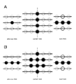
次に、クラスタップ選択部14および予測タップ選択部15の動作について説明する。クラスタップ選択部14および予測タップ選択部15は、モードと動きクラスとに応じて所定位置の画素をクラスタップおよび予測タップとして抽出する。モード0、1、2、3に対応するタップ構造の一例を図7、図8、図9および図10に示す。図7〜図10において、動きクラス0、1の時にクラスタップまたは予測タップとして抽出される画素を黒丸で示し、動きクラス2、3の時にクラスタップまたは予測タップとして抽出される画素を白丸で示した。また、クラスタップまたは予測タップとして抽出される画素以外の画素は、全て点線の丸で示した。
【0026】
モード0におけるタップ構造の一例を図7に示す。図7Aに示すように、動きクラス0、1と動きクラス2、3とでクラスタップ構造が一致する。すなわち、何れの動きクラスにおいても、現在フィールドから5個、現在フィールドの1フィールド後のフィールドから2個の計7個の画素がクラスタップとして抽出される。また、図7Bに示すように、予測タップ構造が動きクラス0、1と動きクラス2、3とで一致する。すなわち、現在フィールドから9個、現在フィールドの1フィールド前および1フィールド後の各フィールドからそれぞれ2個の計13個の画素が予測タップとして抽出される。
【0027】
モード1におけるタップ構造の一例を図8に示す。動きクラス0、1の場合には、図8Aにて黒丸で示す位置の画素(すなわち、現在フィールドから4個、現在フィールドの1フィールド前および1フィールド後の各フィールドからそれぞれ1個および3個の計8個)がクラスタップとして抽出される。また、動きクラス2、3の場合には、図8Aにて白丸で示す位置の画素(現在フィールドから4個、現在フィールドの1フィールド後の各フィールドから5個の計8個)がクラスタップとして抽出される。一方、動きクラス0、1の場合、図8Bにて黒丸で示す位置の画素(現在フィールドから8個、現在フィールドの1フィールド前および1フィールド後の各フィールドからそれぞれ3個の計14個)が予測タップとして抽出される。また、動きクラス2、3の場合には、図8Bにて白丸で示す位置の画素(現在フィールドから8個、現在フィールドの1フィールド後の各フィールドから5個の計13個)が予測タップとして抽出される。
【0028】
モード2におけるタップ構造の一例を図9に示す。図9Aに示すように、動きクラス0、1と動きクラス2、3とでクラスタップ構造が一致する。すなわち、何れの動きクラスにおいても、現在フィールドから5個、現在フィールドの1フィールド後のフィールドから2個の計7個の画素がクラスタップとして抽出される。一方、動きクラス0、1の場合、図9Bにて黒丸で示す位置の画素(現在フィールドから9個、現在フィールドの1フィールド前および1フィールド後の各フィールドからそれぞれ2個の計13個)が予測タップとして抽出される。また、動きクラス2、3の場合には、図8Bにて白丸で示す位置の画素(現在フィールドから9個、現在フィールドの1フィールド後のフィールドから6個の計15個)が予測タップとして抽出される。
【0029】
モード3におけるタップ構造の一例を図10に示す。動きクラス0、1の場合には、図10Aにて黒丸で示す位置の画素(すなわち、現在フィールドから2個、現在フィールドの1フィールド前および1フィールド後の各フィールドからそれぞれ3個の計8個)がクラスタップとして抽出される。また、動きクラス2、3の場合には、図8Aにて白丸で示す位置の画素(現在フィールドから6個、現在フィールドの1フィールド前および1フィールド後の各フィールドから1個の計8個)がクラスタップとして抽出される。一方、図10Bに示すように、動きクラス0、1と動きクラス2、3とで予測タップ構造が一致する。すなわち、何れの動きクラスにおいても、現在フィールドから8個、現在フィールドの1フィールド前および1フィールド後の各フィールドからそれぞれ3個の計14個の画素がクラスタップとして抽出される。
【0030】
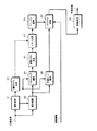
次に、学習、すなわち上述したマッピングを行うに際して使用される予測係数の算出について説明する。図1における入力画像と同一の信号形式を有する画像が生徒画像として動き推定部21および動き補償部22に供給される。動き推定部21は、図1中の動き推定部11と同様な処理を行う。すなわち、動き推定部21は、生徒画像内の注目画素の動きベクトルを推定し、推定した動きベクトルを動き補償部22に供給する。また、動き推定部21は、動きベクトルと共に、その信頼性を示す情報を動きクラス決定部23に供給する。一方、動き補償部22は、図1中の動き補償部12と同様な動き補償処理を行う。この動き補償処理の結果として生成される画像がクラスタップ選択部24と予測タップ選択部25とに供給される。
【0031】
動きクラス決定部23は、図1中の動きクラス決定部13と同様な処理を行って動きクラスを決定し、決定した動きクラスを示す情報をクラスタップ選択部24、予測タップ選択部25およびクラス決定部27に供給する。クラスタップ選択部24は、図1中のクラスタップ選択部14と同一位置の画素をクラスタップとして抽出し、抽出したクラスタップのデータを空間クラス決定部26に供給する。空間クラス決定部26は、供給されるデータに基づいて図1中の空間クラス決定部16と同様な処理を行うことによって空間クラスを決定し、決定した空間クラスを示す情報をクラス決定部27に供給する。
【0032】
クラス決定部27は、図1中のクラス決定部17と同様な処理を行うことにより、最終的なクラスを決定し、最終的なクラスを示す情報をマトリクス選択部28に供給する。マトリクス選択部28は、最終的なクラスに対応するマトリクスを選択し、選択したマトリクスに係るデータをマトリクス加算部29に供給する。
【0033】
一方、予測タップ選択部25は、図1中の予測タップ選択部15と同一位置の画素を予測タップとして抽出し、抽出した予測タップのデータをマトリクス加算部29に供給する。マトリクス加算部29には、さらに、図1における出力画像と同一の信号形式の画像が教師画像として供給される。マトリクス加算部29には、マトリクス選択部28から供給されるデータに、予測タップのデータおよび教師画像に基づく演算結果を足し込む処理を行うことにより、正規方程式のデータを生成する。正規方程式のデータは、マトリクス加算部29から係数決定部30に供給される。係数決定部30は、正規方程式を解く演算を行うことにより、予測係数を算出する。算出された予測係数は、例えば図示しないメモリに一旦記憶され、図1中の予測係数選択部内のメモリにロードされる等の方法により、図1を参照して上述した演算処理において使用されることが可能となる。
【0034】
次に、予測係数を算出するための演算について説明する。上述の式(1)において、学習前は予測係数w1 ,‥‥,wn が未定係数である。学習は、クラス毎に複数の教師画像を入力することによって行う。教師画像の種類数をmと表記する場合、式(1)から、以下の式(2)が設定される。
【0035】
yk =w1 ×xk1+w2 ×xk2+‥‥+wn ×xkn (2)
(k=1,2,‥‥,m)
m>nの場合、予測係数w1 ,‥‥,wn は一意に決まらないので、誤差ベクトルeの要素ek を以下の式(3)で定義して、式(4)によって定義される誤差ベクトルeを最小とするように予測係数を定めるようにする。すなわち、いわゆる最小2乗法によって予測係数を一意に定める。
【0036】
ek =yk −{w1 ×xk1+w2 ×xk2+‥‥+wn ×xkn} (3)
(k=1,2,‥‥m)
【0037】
【数1】

式(4)のe2 を最小とする予測係数を求めるための実際的な計算方法としては、e2 を予測係数wi (i=1,2‥‥)で偏微分し(式(5))、iの各値について偏微分値が0となるように各予測係数wi を定めれば良い。
【0039】
【数2】
式(5)から各予測係数wi を定める具体的な手順について説明する。式(6)、(7)のようにXji,Yi を定義すると、式(5)は、式(8)の行列式の形に書くことができる。
【0041】
【数3】
【数4】
【数5】
式(8)が一般に正規方程式と呼ばれるものである。マトリクス加算部29は、正規方程式(8)中のパラメータを算出する。係数決定部30は、算出されたパラメータに基づいて掃き出し法等の一般的な行列解法に従って正規方程式(8)を解くことにより、予測係数wi (i=1,2,‥‥,n)を算出する。
【0045】
上述したこの発明の一実施形態では、動き推定部11による処理結果として得られる動きベクトルがクラスタップ選択、予測タップ選択およびクラス決定回路17におけるクラス分類にも反映するようになされているが、フィールド周波数変換処理に対する動きベクトルの反映のさせ方はこれに限定されるものではない。例えば、動きベクトルを動き補償にのみ使用する構成、動きベクトルを動き補償とクラスタップおよび/または予測タップの選択に使用する構成、動きベクトルを動き補償とクラス分類に使用する構成等によっても、入力画像の動きが大きい場合にフィールド周波数変換に変換性能をある程度向上させることが可能である。
【0046】
一般的に、より多くの構成要素の動作に動きベクトルが反映されるように構成する程、入力画像の動きが大きい場合の変換性能は良くなるが、回路構成は大型化すると考えられる。従って、この発明の適用に際しては、装置に要求される、変換性能、回路規模、コスト等の条件により適合する構成用いるようにすれば良い。
【0047】
この発明は、上述したこの発明の一実施形態に限定されるものでは無く、この発明の主旨を逸脱しない範囲内で様々な変形や応用が可能である。
【0048】
【発明の効果】
この発明によれば、入力画像における動き量に基づいて動き補償された画像に対してクラス分類適応処理を適用することにより、フィールド周波数変換がなされる。このため、動き量が大きい場合等においても、変換処理の精度を向上させることができる。
【0049】
特に、クラス分類適応処理における演算に使用される画像データを切り出す際に、動き量に応じた処理を行うようにすれば、変換処理の精度をより向上させることができる。
【0050】
また、注目画素の周辺における画像データのレベル分布による空間クラスに加えて、動き量による動きクラスを合成したクラスを形成すれば、変換処理の精度をより向上させることができる。
【図面の簡単な説明】
【図1】この発明の一実施形態における、フィールド周波数変換処理に係る構成について説明するためのブロック図である。
【図2】ブロックマッチングについて説明するための略線図である。
【図3】入力画像内の画素と出力画像内の画素との位置関係について説明するための略線図である。
【図4】モードについて説明するための略線図である。
【図5】モード0およびモード3における動き補償処理について説明するための略線図である。
【図6】モード1およびモード2における動き補償処理について説明するための略線図である。
【図7】モード0におけるタップ構造について説明するための略線図である。
【図8】モード1におけるタップ構造について説明するための略線図である。
【図9】モード2におけるタップ構造について説明するための略線図である。
【図10】モード3におけるタップ構造について説明するための略線図である。
【図11】この発明の一実施形態における、学習に係る処理について説明するためのブロック図である。
【符号の説明】
11・・・動き推定部、12・・・動き補償部、21・・・動き推定部、22・・・動き補償部[0001]
BACKGROUND OF THE INVENTION
The present invention relates to a field frequency conversion apparatus and a conversion method for performing image information conversion on an input image for the purpose of improving resolution, for example.
[0002]
[Prior art]
As a field frequency conversion method for converting a field frequency from, for example, 50 Hz to 60 Hz, a process of estimating a motion between fields and generating a new field between fields using the estimated motion amount is known. However, such a method has a problem that if the motion estimation fails, the processing result is directly affected. Further, such a method is merely an interpolation process, and the temporal or spatial resolution cannot be improved.
[0003]
In addition, the applicant of the present invention uses the image data extracted from a plurality of fields in the original image, and generates a new field by the class classification adaptive process, thereby adjusting the field frequency.For example, from 50Hz to 100HzThe conversion method to convert is proposed previously.Here, the class classification adaptive processing is the following processing. That is, a predetermined range of image data is cut out from the input image, the level distribution of the cut-out image data is detected, and classification is performed based on the detection result. Then, an output image such as a field-doubled image is obtained as a result of a calculation based on a prediction coefficient determined in advance for each classified class and a predetermined range of image data cut out from the input image. Here, the prediction coefficient is an arithmetic process based on an image having the same signal format as the output image (referred to as a teacher image) and an image having the same signal format as the input image (referred to as a student image). Determined by.
[0004]
[Problems to be solved by the invention]
However, in such a method, when the amount of motion of the input image is larger than the range of image data to be extracted, the correct class classification adaptation process cannot be performed, and thus a correct field cannot be generated.
[0005]
Accordingly, an object of the present invention is to provide a field frequency conversion device and a conversion method capable of performing field frequency conversion more accurately, particularly when the amount of motion of an input image is large.
[0006]
[Means for Solving the Problems]
The invention of claim 1By creating a new field between the fields of the input image
Field frequency that forms an output image with more fields than the number of fields in the input image
In the number converter,
Input imageThe motion vector of the pixel of interest that is the target of processingMotion estimation means;
MovementBy vectorMotion compensation means for performing motion compensation processing on the input image;
MovementDepending on the magnitude of the vector valueMotion class determining means for determining a motion class;
From the output of the motion compensation means,Multiple pixels around the pixel of interestFirst image cutting means for cutting image data;
Cut out by the first image cutout meanspluralimage dataofFor levelClothDetected and detectedLevel distributionOn the basis of thespaceDetermine classspaceClass decision means;
Class determining means for determining a class by combining the motion class from the motion class determining means and the space class from the space class determining means;
From the output of the motion compensation means,Multiple pixels around the pixel of interestA second image cutting means for cutting image data;
classEach ofPre-determined corresponding toFor estimating the output image signalStores prediction coefficients, and class determination means from the stored prediction coefficientsClass fromCoefficient storage means for outputting the one corresponding to
Cut out by the second image cutting meanspluralImage data and prediction coefficients supplied from coefficient storage means;Sum of productsPerform operationGenerate a predicted value of the image data of the output imageArithmetic processing meansAnd
The prediction coefficient is obtained by learning in advance for each class so as to minimize an error between the generated value and the true value of the pixel when the pixel of the output image signal is generated by the product-sum operation. Remembered
This is a field frequency converter characterized by the above.
[0007]
The invention of claim 5In a field frequency conversion method for forming an output image having a number of fields larger than the number of fields of the input image by generating a new field between the fields of the input image,
Input imageThe motion vector of the pixel of interest that is the target of processingA motion estimation step;
MovementBy vectorA motion compensation step for performing motion compensation processing on the input image;
MovementDepending on the magnitude of the vector valueA motion class determining step for determining a motion class;
From the output of the motion compensation step,Multiple pixels around the pixel of interestA first image cutting step for cutting image data;
Cut out by the first image cutout steppluralimage dataofFor levelClothDetected and detectedLevel distributionOn the basis of thespaceDetermine classspaceA class determination step;
A class determination step for determining a class by combining the motion class from the motion class determination step and the space class from the space class determination step;
From the output of the motion compensation step,Multiple pixels around the pixel of interestA second image cutting step for cutting image data;
classEach ofPre-determined corresponding toFor estimating the output image signalThe prediction coefficient is stored, and the class determination step is performed from the stored prediction coefficients.Class fromA coefficient storage step for outputting the one corresponding to
Cut out by the second image cutout steppluralImage data and prediction coefficients supplied from the coefficient storage stepSum of productsPerform operationGenerate a predicted value of the image data of the output imageArithmetic processing stepAnd
The prediction coefficient is obtained by learning for each class in advance so as to minimize an error between the generated value and the true value of the pixel when the pixel of the output image signal is generated by the product-sum operation. Remembered
This is a field frequency conversion method characterized by the above.
[0008]
According to the invention as described above, the amount of motion of the input image can be reflected when performing the class classification adaptive processing.
[0009]
DETAILED DESCRIPTION OF THE INVENTION
An embodiment of the present invention will be described below with reference to the drawings as appropriate. FIG. 1 shows an example of a configuration relating to mapping in one embodiment of the present invention, that is, processing for converting a field frequency. Such a configuration is, for example, an input image of 50 Hz.10A process of converting to an output image of 0 Hz is performed. An input image is supplied to the
[0010]
On the other hand, the motion
[0011]
The
[0012]
On the other hand, the prediction
[0013]
y = w1X1+ W2X2+ ... + wnXn (1)
Where x1, ..., xnIs the pixel data of each prediction tap, and w1, ..., wnAre each prediction coefficient.
[0014]
Next, the operation of the
[0015]
Such an evaluation value is generated for all candidate blocks in the search range S1, and the position corresponding to the reference block B1 is determined by determining the position of the candidate block having the smallest evaluation value as the position of the candidate block with the best matching. Detect vectors. When blocks shifted by one pixel are used as candidate blocks in the search range S1, s × t candidate blocks are handled in total. The reference block may be set in the past frame and the search range may be set in the current frame. The block matching is disclosed in detail in the previous proposal of the applicant of the present application (for example, see Japanese Patent Application Laid-Open No. 54-124927). What is necessary is just to set a reference block, the magnitude | size of a search range, etc. suitably according to conditions, such as the property of the image used as the object of motion estimation. In one embodiment of the present invention, for example, the block size of the reference block is 6 horizontal pixels × 3 vertical pixels, and the search range is ± 16 pixels only in the horizontal direction.
[0016]
In one embodiment of the present invention, the reliability of the motion vector estimated as described above is determined as follows. That is, when the minimum value of the evaluation value is equal to or greater than a predetermined value such as 180, it is determined that the reliability is low, and the motion vector is invalidated. When the motion vector is invalidated, 0 is output as the motion vector.
[0017]
In the
[0018]
Such a positional relationship is shown in more detail in FIG. Here, one output pixel for each mode is shown with light ink as a representative example. When the pixel in the output image is on the field in the input image, the mode in which the pixel in the output image is at the same position as the pixel in the input image (mode 0), and the pixel in the output image is input There is a mode (mode 3) that exists between pixels in the image. In addition, when the pixel in the output image is on a field generated between the fields in the input image, the pixel in the output image is on the field in the input image that is positioned immediately before the field. And a mode (mode 1) in which there is a pixel whose vertical position coincides with that of the input image, and a position in the vertical direction of the pixel in the output image on the field in the input image located immediately after the field in time. There is a mode (mode 2) in which there is a matching pixel.
[0019]
When the pixel in the output image is on the field in the input image (mode 0 and mode 3), the
[0020]
In FIG. 5, a motion vector estimated between field (N) and field (N + 2) that is a field at time N + 2 is denoted by me_x. In this case, as motion compensation, a process of drawing the field (N−1) and the field (N + 1) by me_x / 2 and −me_x / 2 in the horizontal direction is performed. Thereby, in the field (N−1) and the field (N + 1), it is possible to obtain an image in which the movement in the horizontal direction is apparently almost canceled.
[0021]
FIG. 6 shows an example of processing in
[0022]
Also in FIG. 6, similarly to FIG. 5, a motion vector estimated between field (N) and field (N + 2) that is a field at time N + 2 is denoted by me_x. In this case, as motion compensation, a process of drawing the field (N−1), field (N), and field (N + 1) in the horizontal direction by 3 × me_x / 4, me_x / 4, and −me_x / 4, respectively. Done. By such processing, it is possible to obtain an image in which the horizontal movement is apparently almost canceled in the field (N−1) and the field (N + 1).
[0023]
Next, processing by the motion
[0024]
Motion class 0: motion vector is valid and motion vector value is 0
Motion class 1: The motion vector is valid and the absolute value of the motion vector value is 6 or less.
Motion class 2: The motion vector is valid and the absolute value of the motion vector value is 7 or more.
Motion class 3: motion vector is invalid (at this time, the motion vector value is 0). Here, when it is determined that the reliability of the motion vector is low (as described above, the minimum value of the evaluation value in block matching is The motion vector is invalidated (when it exceeds a predetermined value), and the motion vector is validated otherwise. Further, values such as 6, 7 and the like, which are reference values when determining the
[0025]
Next, operations of the class
[0026]
An example of the tap structure in mode 0 is shown in FIG. As shown in FIG. 7A, the class tap structures match between
[0027]
An example of the tap structure in
[0028]
An example of the tap structure in
[0029]
An example of the tap structure in
[0030]
Next, calculation of a prediction coefficient used when learning, that is, mapping described above will be described. An image having the same signal format as the input image in FIG. 1 is supplied to the
[0031]
The motion
[0032]
The
[0033]
On the other hand, the prediction
[0034]
Next, the calculation for calculating the prediction coefficient will be described. In the above equation (1), before learning, the prediction coefficient w1, ..., wnIs an undetermined coefficient. Learning is performed by inputting a plurality of teacher images for each class. When the number of types of teacher images is expressed as m, the following equation (2) is set from equation (1).
[0035]
yk= W1Xk1+ W2Xk2+ ... + wnXkn (2)
(K = 1, 2,..., M)
If m> n, prediction coefficient w1, ..., wnIs not uniquely determined, the element e of the error vector ekIs defined by the following equation (3), and the prediction coefficient is determined so as to minimize the error vector e defined by equation (4). That is, the prediction coefficient is uniquely determined by a so-called least square method.
[0036]
ek= Yk-{W1Xk1+ W2Xk2+ ... + wnXkn} (3)
(K = 1, 2, ... m)
[0037]
[Expression 1]
E in equation (4)2As a practical calculation method for obtaining the prediction coefficient that minimizes2Prediction coefficient wi(i = 1, 2...) is partially differentiated (formula (5)), and each prediction coefficient w is set so that the partial differential value becomes 0 for each value of i.iShould be determined.
[0039]
[Expression 2]
From equation (5), each prediction coefficient wiA specific procedure for determining the above will be described. X as in equations (6) and (7)ji, Yi(5) can be written in the form of the determinant of equation (8).
[0041]
[Equation 3]
[Expression 4]
[Equation 5]
Equation (8) is generally called a normal equation. The matrix addition unit 29 calculates parameters in the normal equation (8). The
[0045]
In the embodiment of the present invention described above, the motion vector obtained as a result of processing by the
[0046]
In general, it is considered that as the motion vector is reflected in the operation of more components, the conversion performance is improved when the motion of the input image is large, but the circuit configuration is increased. Therefore, when applying the present invention, a configuration suitable for conditions such as conversion performance, circuit scale, and cost required for the apparatus may be used.
[0047]
The present invention is not limited to the above-described embodiment of the present invention, and various modifications and applications can be made without departing from the gist of the present invention.
[0048]
【The invention's effect】
According to the present invention, field frequency conversion is performed by applying the class classification adaptive processing to an image that has been motion compensated based on the amount of motion in the input image. For this reason, even when the amount of motion is large, the accuracy of the conversion process can be improved.
[0049]
In particular, the accuracy of the conversion process can be further improved by performing the process according to the amount of motion when extracting the image data used for the calculation in the class classification adaptive process.
[0050]
Also,Around the pixel of interestFor image data levelSpace class with clothIn addition to the amount of movementBy movement classTheForm a synthesized classThen, the accuracy of the conversion process can be further improved.
[Brief description of the drawings]
FIG. 1 is a block diagram for illustrating a configuration related to a field frequency conversion process in an embodiment of the present invention.
FIG. 2 is a schematic diagram for explaining block matching.
FIG. 3 is a schematic diagram for explaining a positional relationship between a pixel in an input image and a pixel in an output image.
FIG. 4 is a schematic diagram for explaining modes.
FIG. 5 is a schematic diagram for explaining motion compensation processing in mode 0 and
FIG. 6 is a schematic diagram for explaining motion compensation processing in
FIG. 7 is a schematic diagram for illustrating a tap structure in mode 0;
8 is a schematic diagram for illustrating a tap structure in
9 is a schematic diagram for illustrating a tap structure in
10 is a schematic diagram for illustrating a tap structure in
FIG. 11 is a block diagram for explaining processing related to learning in an embodiment of the present invention;
[Explanation of symbols]
DESCRIPTION OF
Claims (5)
入力画像の処理の対象である注目画素の動きベクトルを検出する動き量推定手段と、
上記動きベクトルによって、上記入力画像に対する動き補償処理を行う動き補償手段と、
上記動きベクトルの値の大きさによって、動きクラスを決定する動きクラス決定手段と、
上記動き補償手段の出力から、上記注目画素の周辺の複数の画像データを切り出す第1の画像切り出し手段と、
上記第1の画像切り出し手段によって切り出される複数の画像データのレベル分布を検出し、検出したレベル分布に基づいて空間クラスを決定する空間クラス決定手段と、
上記動きクラス決定手段からの上記動きクラスと、上記空間クラス決定手段からの上記空間クラスとを合成してクラスを決定するクラス決定手段と、
上記動き補償手段の出力から、上記注目画素の周辺の複数の画像データを切り出す第2の画像切り出し手段と、
上記クラスのそれぞれに対応して予め決定され、出力画像信号を推定するための予測係数を記憶し、記憶している予測係数の内から、上記クラス決定手段からのクラスに対応するものを出力する係数記憶手段と、
上記第2の画像切り出し手段によって切り出される複数の画像データと、上記係数記憶手段から供給される予測係数との積和演算を行い、上記出力画像の画像データの予測値を生成する演算処理手段とを有し、
上記予測係数は、上記積和演算によって、上記出力画像信号の画素を生成した時に、生成された値と上記画素の真値との誤差を最小にするように、上記クラス毎に予め学習によって求められて上記係数記憶手段に記憶される
ことを特徴とするフィールド周波数変換装置。 In a field frequency conversion device for forming an output image having a field number larger than the number of fields of the input image by generating a new field between the fields of the input image,
A motion amount estimating means for detecting a motion vector of a target pixel which is a target of processing of an input image;
Motion compensation means for performing motion compensation processing on the input image according to the motion vector ;
Motion class determining means for determining a motion class according to the magnitude of the value of the motion vector ;
First image cutout means for cutting out a plurality of image data around the target pixel from the output of the motion compensation means;
A space class determining means for determining a spatial class based on a level distribution of a plurality of image data detected, the detected level distribution to be cut by the first image cutout unit,
Class determining means for determining a class by combining the motion class from the motion class determining means and the space class from the space class determining means;
A second image cutout unit that cuts out a plurality of image data around the target pixel from the output of the motion compensation unit;
Predicted corresponding to each of the classes , storing prediction coefficients for estimating the output image signal, and outputting the stored prediction coefficients corresponding to the class from the class determining means Coefficient storage means;
Said plurality of image data cut out by the second image cutout unit, have rows product-sum operation of the prediction coefficients supplied from the coefficient storage means, processing means for generating a predicted value of the image data of the output image It has a door,
The prediction coefficient is obtained by learning in advance for each class so as to minimize an error between the generated value and the true value of the pixel when the pixel of the output image signal is generated by the product-sum operation. And stored in the coefficient storage means .
上記第1の画像切り出し手段は、
上記動きクラスに応じて切り出す複数の画像データを設定することを特徴とするフィールド周波数変換装置。In claim 1,
The first image cutout means includes:
A field frequency conversion device, wherein a plurality of image data to be cut out is set according to the motion class .
上記第2の画像切り出し手段は、
上記動きクラスに応じて切り出す複数の画像データを設定することを特徴とするフィールド周波数変換装置。In claim 1,
The second image cutout means includes:
A field frequency conversion device, wherein a plurality of image data to be cut out is set according to the motion class .
上記動き量推定手段が上記動きベクトルと共に、検出された動きベクトルの信頼性の情報を出力することを特徴とするフィールド周波数変換装置。 In claim 1,
The field frequency conversion device, wherein the motion amount estimation means outputs information on reliability of the detected motion vector together with the motion vector.
入力画像の処理の対象である注目画素の動きベクトルを検出する動き量推定ステップと、
上記動きベクトルによって、上記入力画像に対する動き補償処理を行う動き補償ステップと、
上記動きベクトルの値の大きさによって、動きクラスを決定する動きクラス決定ステップと、
上記動き補償ステップの出力から、上記注目画素の周辺の複数の画像データを切り出す第1の画像切り出しステップと、
上記第1の画像切り出しステップによって切り出される複数の画像データのレベル分布 を検出し、検出したレベル分布に基づいて空間クラスを決定する空間クラス決定ステップと、
上記動きクラス決定ステップからの上記動きクラスと、上記空間クラス決定ステップからの上記空間クラスとを合成してクラスを決定するクラス決定ステップと、
上記動き補償ステップの出力から、上記注目画素の周辺の複数の画像データを切り出す第2の画像切り出しステップと、
上記クラスのそれぞれに対応して予め決定され、出力画像信号を推定するための予測係数を記憶し、記憶している予測係数の内から、上記クラス決定ステップからのクラスに対応するものを出力する係数記憶ステップと、
上記第2の画像切り出しステップによって切り出される複数の画像データと、上記係数記憶ステップから供給される予測係数との積和演算を行い、上記出力画像の画像データの予測値を生成する演算処理ステップとを有し、
上記予測係数は、上記積和演算によって、上記出力画像信号の画素を生成した時に、生成された値と上記画素の真値との誤差を最小にするように、上記クラス毎に予め学習によって求められて上記係数記憶ステップに記憶される
ことを特徴とするフィールド周波数変換方法。 In a field frequency conversion method for forming an output image having a field number larger than the number of fields of the input image by generating a new field between the fields of the input image,
A motion amount estimation step of detecting a motion vector of a target pixel that is a target of processing of an input image;
A motion compensation step for performing motion compensation processing on the input image by the motion vector ;
A motion class determining step for determining a motion class according to the magnitude of the value of the motion vector ;
A first image cutout step of cutting out a plurality of image data around the pixel of interest from the output of the motion compensation step;
A space class determining step of determining a spatial class plurality of detecting the level distribution of the image data, based on the detected level distribution to be cut by the first image extraction step,
A class determining step for determining a class by combining the motion class from the motion class determining step and the space class from the space class determining step;
A second image cutout step of cutting out a plurality of image data around the pixel of interest from the output of the motion compensation step;
Predicted corresponding to each of the classes , storing prediction coefficients for estimating the output image signal, and outputting the stored prediction coefficients corresponding to the class from the class determining step. A coefficient storage step;
A plurality of image data cut out by the second image extraction step, have rows product-sum operation of the prediction coefficients supplied from the coefficient storage step, the arithmetic processing step of generating a predicted value of the image data of the output image It has a door,
The prediction coefficient is obtained by learning in advance for each class so as to minimize an error between the generated value and the true value of the pixel when the pixel of the output image signal is generated by the product-sum operation. And stored in the coefficient storing step .
Priority Applications (1)
| Application Number | Priority Date | Filing Date | Title |
|---|---|---|---|
| JP12729299A JP4250806B2 (en) | 1999-05-07 | 1999-05-07 | Field frequency conversion device and conversion method |
Applications Claiming Priority (1)
| Application Number | Priority Date | Filing Date | Title |
|---|---|---|---|
| JP12729299A JP4250806B2 (en) | 1999-05-07 | 1999-05-07 | Field frequency conversion device and conversion method |
Publications (3)
| Publication Number | Publication Date |
|---|---|
| JP2000324495A JP2000324495A (en) | 2000-11-24 |
| JP2000324495A5 JP2000324495A5 (en) | 2006-04-06 |
| JP4250806B2 true JP4250806B2 (en) | 2009-04-08 |
Family
ID=14956363
Family Applications (1)
| Application Number | Title | Priority Date | Filing Date |
|---|---|---|---|
| JP12729299A Expired - Fee Related JP4250806B2 (en) | 1999-05-07 | 1999-05-07 | Field frequency conversion device and conversion method |
Country Status (1)
| Country | Link |
|---|---|
| JP (1) | JP4250806B2 (en) |
Families Citing this family (4)
| Publication number | Priority date | Publication date | Assignee | Title |
|---|---|---|---|---|
| JP4462823B2 (en) | 2002-11-20 | 2010-05-12 | ソニー株式会社 | Image signal processing apparatus and processing method, coefficient data generating apparatus and generating method used therefor, and program for executing each method |
| JP4591767B2 (en) * | 2005-02-28 | 2010-12-01 | ソニー株式会社 | Encoding apparatus and method, decoding apparatus and method, image processing system, recording medium, and program |
| JP4748127B2 (en) * | 2007-07-24 | 2011-08-17 | ソニー株式会社 | Information processing apparatus and method, recording medium, and program |
| JP5201408B2 (en) * | 2008-09-30 | 2013-06-05 | ソニー株式会社 | Frame frequency conversion apparatus, frame frequency conversion method, program for executing the method, computer-readable recording medium recording the program, motion vector detection apparatus, and prediction coefficient generation apparatus |
-
1999
- 1999-05-07 JP JP12729299A patent/JP4250806B2/en not_active Expired - Fee Related
Also Published As
| Publication number | Publication date |
|---|---|
| JP2000324495A (en) | 2000-11-24 |
Similar Documents
| Publication | Publication Date | Title |
|---|---|---|
| KR100787675B1 (en) | Method, apparatus and computer program product for generating interpolation frame | |
| JP2576771B2 (en) | Motion compensation prediction device | |
| JP2978406B2 (en) | Apparatus and method for generating motion vector field by eliminating local anomalies | |
| US20090278991A1 (en) | Method for interpolating a previous and subsequent image of an input image sequence | |
| CN101170673A (en) | Device for detecting occlusion area and method thereof | |
| KR20020064440A (en) | Apparatus and method for compensating video motions | |
| KR20070094520A (en) | Image processing apparatus and method and program | |
| KR20010075507A (en) | Motion estimation | |
| JP2005506626A (en) | Motion estimation unit and method, and image processing apparatus having such a motion estimation unit | |
| JP2000069435A5 (en) | ||
| JP4385077B1 (en) | Motion vector detection device and image processing device | |
| JPH0787481A (en) | Fault detector | |
| JP5025645B2 (en) | Motion estimation method | |
| WO2011074121A1 (en) | Device and method for detecting motion vector | |
| JP4407015B2 (en) | Noise removing apparatus and noise removing method | |
| JP4250806B2 (en) | Field frequency conversion device and conversion method | |
| US9106926B1 (en) | Using double confirmation of motion vectors to determine occluded regions in images | |
| US7522748B2 (en) | Method and apparatus for processing image data and semiconductor storage device | |
| JP3175914B2 (en) | Image encoding method and image encoding device | |
| JP2006215657A (en) | Method, apparatus, program and program storage medium for detecting motion vector | |
| JPH057371A (en) | Motion vector detector | |
| JP4250598B2 (en) | Motion compensation IP conversion processing apparatus and motion compensation IP conversion processing method | |
| JP2009065283A (en) | Image shake correction apparatus | |
| JP4470282B2 (en) | Image processing apparatus and image processing method | |
| JP3020299B2 (en) | Motion vector detection device |
Legal Events
| Date | Code | Title | Description |
|---|---|---|---|
| A521 | Written amendment |
Free format text: JAPANESE INTERMEDIATE CODE: A523 Effective date: 20060216 |
|
| A621 | Written request for application examination |
Free format text: JAPANESE INTERMEDIATE CODE: A621 Effective date: 20060216 |
|
| A131 | Notification of reasons for refusal |
Free format text: JAPANESE INTERMEDIATE CODE: A131 Effective date: 20081007 |
|
| A521 | Written amendment |
Free format text: JAPANESE INTERMEDIATE CODE: A523 Effective date: 20081127 |
|
| TRDD | Decision of grant or rejection written | ||
| A01 | Written decision to grant a patent or to grant a registration (utility model) |
Free format text: JAPANESE INTERMEDIATE CODE: A01 Effective date: 20081224 |
|
| A01 | Written decision to grant a patent or to grant a registration (utility model) |
Free format text: JAPANESE INTERMEDIATE CODE: A01 |
|
| A61 | First payment of annual fees (during grant procedure) |
Free format text: JAPANESE INTERMEDIATE CODE: A61 Effective date: 20090106 |
|
| FPAY | Renewal fee payment (event date is renewal date of database) |
Free format text: PAYMENT UNTIL: 20120130 Year of fee payment: 3 |
|
| FPAY | Renewal fee payment (event date is renewal date of database) |
Free format text: PAYMENT UNTIL: 20130130 Year of fee payment: 4 |
|
| FPAY | Renewal fee payment (event date is renewal date of database) |
Free format text: PAYMENT UNTIL: 20140130 Year of fee payment: 5 |
|
| R250 | Receipt of annual fees |
Free format text: JAPANESE INTERMEDIATE CODE: R250 |
|
| R250 | Receipt of annual fees |
Free format text: JAPANESE INTERMEDIATE CODE: R250 |
|
| LAPS | Cancellation because of no payment of annual fees |