JP4248632B2 - Method for producing package of internal and external structure and equipment, and on-site construction method using the package - Google Patents
Method for producing package of internal and external structure and equipment, and on-site construction method using the package Download PDFInfo
- Publication number
- JP4248632B2 JP4248632B2 JP29038898A JP29038898A JP4248632B2 JP 4248632 B2 JP4248632 B2 JP 4248632B2 JP 29038898 A JP29038898 A JP 29038898A JP 29038898 A JP29038898 A JP 29038898A JP 4248632 B2 JP4248632 B2 JP 4248632B2
- Authority
- JP
- Japan
- Prior art keywords
- column
- package
- internal structure
- frame
- external structure
- Prior art date
- Legal status (The legal status is an assumption and is not a legal conclusion. Google has not performed a legal analysis and makes no representation as to the accuracy of the status listed.)
- Expired - Fee Related
Links
Images


Classifications
-
- F—MECHANICAL ENGINEERING; LIGHTING; HEATING; WEAPONS; BLASTING
- F25—REFRIGERATION OR COOLING; COMBINED HEATING AND REFRIGERATION SYSTEMS; HEAT PUMP SYSTEMS; MANUFACTURE OR STORAGE OF ICE; LIQUEFACTION SOLIDIFICATION OF GASES
- F25J—LIQUEFACTION, SOLIDIFICATION OR SEPARATION OF GASES OR GASEOUS OR LIQUEFIED GASEOUS MIXTURES BY PRESSURE AND COLD TREATMENT OR BY BRINGING THEM INTO THE SUPERCRITICAL STATE
- F25J3/00—Processes or apparatus for separating the constituents of gaseous or liquefied gaseous mixtures involving the use of liquefaction or solidification
- F25J3/02—Processes or apparatus for separating the constituents of gaseous or liquefied gaseous mixtures involving the use of liquefaction or solidification by rectification, i.e. by continuous interchange of heat and material between a vapour stream and a liquid stream
- F25J3/04—Processes or apparatus for separating the constituents of gaseous or liquefied gaseous mixtures involving the use of liquefaction or solidification by rectification, i.e. by continuous interchange of heat and material between a vapour stream and a liquid stream for air
- F25J3/04763—Start-up or control of the process; Details of the apparatus used
- F25J3/04866—Construction and layout of air fractionation equipments, e.g. valves, machines
- F25J3/04945—Details of internal structure; insulation and housing of the cold box
-
- F—MECHANICAL ENGINEERING; LIGHTING; HEATING; WEAPONS; BLASTING
- F25—REFRIGERATION OR COOLING; COMBINED HEATING AND REFRIGERATION SYSTEMS; HEAT PUMP SYSTEMS; MANUFACTURE OR STORAGE OF ICE; LIQUEFACTION SOLIDIFICATION OF GASES
- F25J—LIQUEFACTION, SOLIDIFICATION OR SEPARATION OF GASES OR GASEOUS OR LIQUEFIED GASEOUS MIXTURES BY PRESSURE AND COLD TREATMENT OR BY BRINGING THEM INTO THE SUPERCRITICAL STATE
- F25J3/00—Processes or apparatus for separating the constituents of gaseous or liquefied gaseous mixtures involving the use of liquefaction or solidification
- F25J3/02—Processes or apparatus for separating the constituents of gaseous or liquefied gaseous mixtures involving the use of liquefaction or solidification by rectification, i.e. by continuous interchange of heat and material between a vapour stream and a liquid stream
- F25J3/04—Processes or apparatus for separating the constituents of gaseous or liquefied gaseous mixtures involving the use of liquefaction or solidification by rectification, i.e. by continuous interchange of heat and material between a vapour stream and a liquid stream for air
- F25J3/04763—Start-up or control of the process; Details of the apparatus used
- F25J3/04866—Construction and layout of air fractionation equipments, e.g. valves, machines
- F25J3/0489—Modularity and arrangement of parts of the air fractionation unit, in particular of the cold box, e.g. pre-fabrication, assembling and erection, dimensions, horizontal layout "plot"
-
- B—PERFORMING OPERATIONS; TRANSPORTING
- B01—PHYSICAL OR CHEMICAL PROCESSES OR APPARATUS IN GENERAL
- B01J—CHEMICAL OR PHYSICAL PROCESSES, e.g. CATALYSIS OR COLLOID CHEMISTRY; THEIR RELEVANT APPARATUS
- B01J2219/00—Chemical, physical or physico-chemical processes in general; Their relevant apparatus
- B01J2219/32—Details relating to packing elements in the form of grids or built-up elements for forming a unit of module inside the apparatus for mass or heat transfer
- B01J2219/322—Basic shape of the elements
- B01J2219/32203—Sheets
- B01J2219/32275—Mounting or joining of the blocks or sheets within the column or vessel
-
- F—MECHANICAL ENGINEERING; LIGHTING; HEATING; WEAPONS; BLASTING
- F25—REFRIGERATION OR COOLING; COMBINED HEATING AND REFRIGERATION SYSTEMS; HEAT PUMP SYSTEMS; MANUFACTURE OR STORAGE OF ICE; LIQUEFACTION SOLIDIFICATION OF GASES
- F25J—LIQUEFACTION, SOLIDIFICATION OR SEPARATION OF GASES OR GASEOUS OR LIQUEFIED GASEOUS MIXTURES BY PRESSURE AND COLD TREATMENT OR BY BRINGING THEM INTO THE SUPERCRITICAL STATE
- F25J2290/00—Other details not covered by groups F25J2200/00 - F25J2280/00
- F25J2290/42—Modularity, pre-fabrication of modules, assembling and erection, horizontal layout, i.e. plot plan, and vertical arrangement of parts of the cryogenic unit, e.g. of the cold box
-
- Y—GENERAL TAGGING OF NEW TECHNOLOGICAL DEVELOPMENTS; GENERAL TAGGING OF CROSS-SECTIONAL TECHNOLOGIES SPANNING OVER SEVERAL SECTIONS OF THE IPC; TECHNICAL SUBJECTS COVERED BY FORMER USPC CROSS-REFERENCE ART COLLECTIONS [XRACs] AND DIGESTS
- Y10—TECHNICAL SUBJECTS COVERED BY FORMER USPC
- Y10T—TECHNICAL SUBJECTS COVERED BY FORMER US CLASSIFICATION
- Y10T29/00—Metal working
- Y10T29/49—Method of mechanical manufacture
- Y10T29/49826—Assembling or joining
- Y10T29/49904—Assembling a subassembly, then assembling with a second subassembly
-
- Y—GENERAL TAGGING OF NEW TECHNOLOGICAL DEVELOPMENTS; GENERAL TAGGING OF CROSS-SECTIONAL TECHNOLOGIES SPANNING OVER SEVERAL SECTIONS OF THE IPC; TECHNICAL SUBJECTS COVERED BY FORMER USPC CROSS-REFERENCE ART COLLECTIONS [XRACs] AND DIGESTS
- Y10—TECHNICAL SUBJECTS COVERED BY FORMER USPC
- Y10T—TECHNICAL SUBJECTS COVERED BY FORMER US CLASSIFICATION
- Y10T29/00—Metal working
- Y10T29/53—Means to assemble or disassemble
- Y10T29/53443—Means to assemble or disassemble container and fluid component
Landscapes
- Engineering & Computer Science (AREA)
- Physics & Mathematics (AREA)
- Mechanical Engineering (AREA)
- Thermal Sciences (AREA)
- General Engineering & Computer Science (AREA)
- Separation By Low-Temperature Treatments (AREA)
- Filling Or Discharging Of Gas Storage Vessels (AREA)
- Conveying And Assembling Of Building Elements In Situ (AREA)
- Sewage (AREA)
Description
【0001】
【発明の属する技術分野】
本発明は、流体密封内部構造と、内部構造を包囲する外部構造と、少なくとも内部構造の機能設備品と、を組立てることによりパッケージを作製する方法に関する。上記内部構造は流体供給プラントの少なくとも一部を形成するように意図される。
【0002】
特に、本発明は、空気蒸留カラムのパッケージの作製に適用される。空気蒸留カラムはその支持枠体により包囲され、また同カラムにはその機能設備品が取付けられる。
【0003】
【従来の技術】
空気蒸留カラム、その支持枠体、及びその機能設備品を工業現場に据付けることは、複雑な作業である。何故なら、特に、これ等構造の大きな寸法及び大きな質量は、重い昇降手段の使用や、多チームでの作業を必要とすると共に、とりわけ、作業者が仕事を行うことが必要となる場合がある高さに関連して、人的安全性を維持するための特別の準備を必要とする。
【0004】
カラム、その支持枠体、及びその機能設備品をパッケージとして予め組立てると、上述の据付けを単純化することができる。何故なら、このようなパッケージは通常工場で作製され、次に、据付け現場に搬送されることとなり、現場では実施される作業の数が限られるからである。予め組立てることは、例えば、工業現場が困難な天候条件に晒されている場合、或いは工業現場がカラムを据付ける会社の場所から非常に遠い場合に、特に有利である。
【0005】
このようなパッケージの作製方法が既に幾つか存在する。
【0006】
第1の公知の方法によれば、カラムに装備(設備品の配備)がなされ、次に、枠体がその周りに構築される。この際、必要な種々の接続を順に形成すると共にパッケージに装備を施す処理を順に完了する。
【0007】
第2の方法によれば、非装備状態のカラムが、昇降手段を使用して、枠体中に導入される。枠体の大面積面の1つは、必要な接続や設備品の取付けを行う種々の技術者が接近できるように、全く障害がないようになっている。この方法の最後の段階において、枠体の上述の大面積面は順に構築され、パッケージには最後にこの大面積面の装備がなされる。
【0008】
【発明が解決しようとする課題】
上述の2つの方法は複雑で、遅く、しかも高価である。これ等は、特に、種々の技術者が作業をすることのできるスペースが殆どないことによる。更に、この僅かなスペースのみが使用可能であることは、一方で、安全性の問題をもたらす。即ち、技術者の一部、特に溶接者は、狭い閉鎖されたスペースで作業することを強いられる。また、僅かなスペースは、他方で、組立て及び/または構築作業において柔軟性がないことから、作製の遅延の問題をもたらす。
【0009】
本発明の目的は、単純で、高価でなく、より迅速であると共に、安全性の問題及び組立てエラーを減少させることが可能なパッケージの作製方法を提供することにより、上述の問題を解消することにある。
【0010】
【課題を解決するための手段】
上記目的のため、本発明の主題は、流体密封内部構造と、内部構造を包囲する外部構造と、少なくとも内部構造の機能設備品と、を組立てることによりパッケージを作製する方法であって、内部構造は流体供給プラントの少なくとも一部を形成するように意図され、
内部構造をパッケージの長手方向軸に沿って引込むことにより外部構造中に導入する前に、少なくとも1つの機能設備品の少なくとも一部を、少なくとも内部構造に予め装備することを特徴とする。
【0011】
実施の形態において、本発明に係る方法は、下記の特徴の1つ若しくは複数を具備することができる。
【0012】
外部構造中に内部構造を引込む前に、少なくとも1つの機能設備品の少なくとも一部を、外部構造に予め装備することを具備する特徴。
【0013】
内部構造が、外部構造の温度と大幅に異なる温度で少なくとも1つの流体を密封するための構造からなり、外部構造と概ね熱平衡状態にあるように意図された少なくとも1つの設備品の少なくとも一部を、外部構造に予め装備することを具備する特徴。
【0014】
内部構造が、外部構造の温度と大幅に異なる温度を有する少なくとも1つの流体を密封するための構造からなり、前記流体と概ね熱平衡状態にあるように意図された設備品の少なくとも一部を、内部構造に予め装備することを具備する特徴。
【0015】
外部構造を概ね水平に配置した状態で、外部構造内に配設されたレールに沿って内部構造を移動させることにより、外部構造中に内部構造を引込むことを具備する特徴。
【0016】
内部構造が低温構造であることを具備する特徴。
【0017】
外部構造が少なくとも断熱ジャケットの一部分であることを具備する特徴。
【0018】
内部構造が少なくとも蒸留カラムの一部分であることを具備する特徴。
【0019】
外部構造が、少なくとも、内部構造を支持するための枠体の一部分であることを具備する特徴。
【0020】
また、本発明の別の主題は、流体供給プラントの少なくとも一部を形成するように意図された流体密封内部構造と、内部構造を包囲する外部構造と、少なくとも内部構造に接合された機能設備品と、を具備するアセンブリの現場構築方法であって、前記アセンブリは概ね垂直長手方向軸を有し、
上述のように作製したパッケージを現場で起立させることを特徴とする。
【0021】
本発明は、添付の図面を参照してなされる例示の実施の形態に関する以下の記載を読むことにより、より明確に理解することができる。
【0022】
【発明の実施の形態】
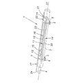
図1及び図2は、パッケージを作製するために組立てる前の、空気蒸留カラム1及びその支持枠体2を示す。
【0023】
軸Δ1を有する概ね円筒形の空気蒸留カラム1は、主蒸留部分3及び副蒸留部分部4を具備する。明らかに小径の副蒸留部分部4即ち「ミナレット」は、主部分3の上端部(図1の左側)を延在させてなる。主部分3は、中圧部、低圧部、及びリボイラを具備する。カラム1は、例えば、約15メートルの長さを有する。
【0024】
カラム1は、2つの離間した横断支持台5上に載置される。支持台5の長手方向の位置は後述する。
【0025】
支持台5にはカラム1を横断する軸のローラを有するランナー6が配設される。各支持台5において、カラムを巻くように金属保護ベルト7が配設される。
【0026】
枠体2は、4つの長手の支柱8を具備する、概ね平行6面体の金属フレームからなる。支柱8は、枠体2の各大面積面において、横断部材9及び対角線ブレース(筋交い)10により接続される。
【0027】
枠体2は、4つの高さ調節可能な足部11上に載置される。
【0028】
本発明によれば、カラム1及び枠体2には、パッケージを作製するため、予め装備がなされる。
【0029】
即ち、カラム1には、その外面において、相分離ポット12及びその液体窒素出口管13と、液体還流管14と、熱交換器15及びその液体供給管16と、ガス出口管17と、が予め装備される。
【0030】
分離ポット12はまた、窒素ガス出口管(図示せず)に接続可能である。
【0031】
これらの設備品は、当業者にとって一般的な技術を使用して、カラム1上に組立てられている。
【0032】
分離ポット12は、概ね円筒形で且つカラム1に対して固定され、その軸は軸Δ1に対して概ね平行となる。
【0033】
ポット12は、その下側部分(図1の右側)において、カラム1に固定された出口管13に接続される。管13は、軸Δ1に対して軸が平行で且つポット12に接続された直線状主部分18と、外部に接続するためのU 字形部分19とを具備する。U 字形部分19はカラム1を概ね横断し且つ部分18を延在させる。カラム1が現場で操作される時、分離ポット12は、カラム外部の貯蔵素子に対して管13を介して運ばれる新鮮な液体の生成に使用される。
【0034】
液体還流管14はカラム1に固定される。管14は、軸Δ1に対して軸が平行な直線状主部分20と、カラム1を概ね横断するU 字形接続部分21とを具備する。主部分20は、その一端部で主蒸留部分3に接続され、他端部で接続部分21に接続される。
【0035】
熱交換器15は、概ね円筒形で且つカラム1に対して固定され、その軸は軸Δ1に対して概ね平行となる。
【0036】
熱交換器15は、その下側部分において、カラム1に固定されたその液体供給管16に接続される。管16は、軸Δ1に対して軸が平行で且つ熱交換器15に接続された直線状主部分22と、カラム1を概ね横断し且つ部分22を延在させるU 字形接続部分23とを具備する。
【0037】
ガス出口管17は、カラム1の副部分4の頂部(図1の左側)に、急激に曲がった部分24を介して接続される。管17は、カラム1の外面に沿って、軸Δ1に対して軸が平行となるように、固定される。
【0038】
ポット12、管13、14、16、17、及び熱交換器15は、枠体2の温度より遥かに低い温度、即ち、カラムが据付けられる現場の周囲温度より低い温度を有する液体を搬送するように設計される。
【0039】
枠体2には、内部ラダー25、カラム1を引込むためのレール26、器具トラック27、及び図を明確にするために図示しない保護板金属加工品が、予め装備される。
【0040】
ラダー25は、枠体2の大面積面の内の1つの面28において、枠体2の内側に長手方向に配置される。ラダー25は、後述のように、パッケージが起立された時、パッケージ内に対して出入可能とするように意図される。
【0041】
レール26は、枠体2の輸送面29(図2の下側)において、枠体2の内側に配設された長手のレールからなる。
【0042】
器具トラック27は、長手の支持板に固定された、器具配管、器具ケーブル、及びガス供給管を具備する。これらの部材は、図を明確にするために概略的に示される。器具トラック27は、現場で蒸留カラム1の操作を可能とする機能設備品である。器具配管は流体取出し管を含む。ガス供給管は、後述のように、カラム1と枠体2との間に配置される絶縁体を湿気のない状態に維持するため、ガスを供給可能とする。
【0043】
器具トラック27、及び特にその支持板は、カラム1の操作中、カラム1に固定された設備品よりも遥かに縮まないように設計される。
【0044】
枠体2はまた、できる限り、保護板金属加工品で被覆される。特に、同板金属加工品は、枠体の面29及び底部30(図2の右側)を除いて、枠体の全面の外側に配設される。板金属加工品は、カラムを保護すると共に断熱するためのジャケットを形成するように意図される。
【0045】
カラム1及び枠体2に予め装備がなされた後、図1及び図2に関して述べたように、軸Δ2が水平となるように足部11が調節される。この位置付け操作は、水準器若しくは当業者にとって一般的な他の技術を使用して実施可能となる。
【0046】
次に、図3及び図4図示の如く、カラム1が枠体2内に導入される。この際、カラム1の上端部(図3の左側)にケーブルを介して接続されたウインチ31により、ランナー6をレール26に沿って走らせながら、カラム1が枠体2中に引込まれる。
【0047】
カラム1は、枠体2内に長手方向に配置される。ここで、2つの支持台5が、枠体2の各大面積面の横断部材9に夫々対向するようにする。カラム1に対する支持台5の長手方向位置は、従って、このような結果を得るように、適当な計測を実施することにより選択される。
【0048】
次に、5つのスクリュージャッキ32(図5参照)が各支持台5に、即ち、構築中のパッケージ33のため、合計10個のジャッキがカラム1と枠体2との間に配置される。
【0049】
図5図示の如く、各支持台5のため、垂直ジャッキ32が、カラム1と枠体2の上側大面積面(図5において)の横断部材9との間に配置され、また、2つの水平ジャッキ32が、夫々、カラム1と枠体2の垂直大面積面(図5において)の横断部材9との間に配置される。3つのジャッキ32の内端部は、カラム1を巻くベルト7に接触し且つこれに対して溶接され、また外端部は、枠体2の対応の横断部材9に対して固定される。
【0050】
2つの垂直ジャッキ32がまた、支持台5の底面と枠体2の面29の横断部材9との間に配置される。これ等ジャッキの上端部は支持台5に固定され、下端部は枠体2に固定される。次に、図5図示の如く、2つの支持台5の下のランナー6が取外される。次に、カラム1が枠体2に対して位置付けられる。ここで、これ等の長手方向軸Δ1、Δ2が平行で、且つ所望の相対位置をとるようにされる。これ等2つの軸の相対位置は、照準器若しくは当業者にとって一般的な他の技術を使用して決定される。
【0051】
上記相対位置はジャッキ32を調節することにより変更可能となる。望ましくは、カラム1が枠体2の概ね中心位置に横たわるように、即ち、Δ1及びΔ2が概ね整一し且つパッケージ32の長手方向軸を規定するように、上記相対位置が選択される。
【0052】
カラム1及び枠体2の相対位置付けが一旦完了すると、これ等は、例えばジャッキ32のナットを点溶接することにより、互いに締結される。
【0053】
次に、管13の接続端部を枠体2の保護板金属加工品に貫通させると共に、カラム1の対応部分に対して器具トラック27の配管及びケーブルを接続すること等により、パッケージ33の装備が完了する。
【0054】
次に、カラム1と枠体2との間に一般的な絶縁体が配設される。
【0055】
最後に、パッケージ33の開口領域を保護するための手段、例えば、防水カバーからなる手段が使用される。
【0056】
次に、パッケージ33は、工業現場に輸送されるように準備される。一旦パッケージ33が現場に到着すると、昇降手段を使用して、同パッケージはその長手方向軸に沿って起立される。
【0057】
長手の支柱8の下端部(図4の右側)が、高さ調節可能な足部上に載置される。次に、軸Δ2の垂直性が、例えば、照準器若しくは当業者にとって一般的な他の技術を使用してチェックされる。
【0058】
カラム1の軸Δ1は枠体2の軸Δ2に対して平行であるため、カラム1が適切に操作するのに必要なカラム1の垂直性は、枠体2が載置される足部の各高さを調節することにより、容易に保証することができる。
【0059】
このようにして、工業現場のグランドに対してパッケージ33の調節を完了させる。
【0060】
最後に、パッケージ33の輸送面29上に保護板金属加工品を配設することにより本方法が完了する。また、パッケージ33の外部環境に対してパッケージ33の設備品が接続される。
【0061】
本発明に係るカラム及び枠体の予装備は、種々の技術者がこれ等2つの構造に対して並行して不都合なく作業を行うことを可能とする。また、設備品は、枠体及びカラムに対していかなる順序でも取付けることができる。これ等は、従来のパッケージ作製方法と異なる。
【0062】
従って、安全性は向上し、実際的に各構造の全面において作業を行うことが可能となる。密閉空間内における有害ガスの濃縮に関連した危険性も減少する。また、保護板金属加工品により天候から保護された状態で、枠体を構築すると共にその外部に装備を行うことが可能となる。
【0063】
枠体に形成された接近用開口の数は、従来のパッケージよりも少なく、従って、枠体の取外し及び再組立ての作業の数を減少させることができる。また、保護板金属加工品を、枠体の3つの大面積面(従来の方法においては一般的に2面)に対して予め取付けることができる。
【0064】
この理由から、本発明に係る方法を実施するために使用される枠体はより堅固で、従って、従来のパッケージ作製方法に比べてより容易に輸送可能である。
【0065】
また、必要とされるものは、引込み作業を行うためのウインチが全てであり、従って、従来のパッケージ作製方法のように、工場において重い昇降手段を使用する必要がない。
【0066】
また、従来の製造方法に比べて、製造時間を25乃至30%削減することが見出されている。より一般的には、外部構造が断熱構造で、内部構造は、例えば、低温タンク、即ち、周囲温度より少なくとも約100℃低い温度の液体を収容するものとすることができる。
【0067】
本発明に係る方法は、また、内部及び外部構造の一部分からなるパッケージを作製するために使用することができ、ここで、内部構造は、例えば、カラムの一部分であり、外部構造は対応の枠体の一部分となる。
【0068】
【発明の効果】
本発明によれば、単純で、高価でなく、より迅速であると共に、安全性の問題及び組立てエラーを減少させることが可能なパッケージの作製方法を提供することができる。
【図面の簡単な説明】
【図1】本発明に従って予装備が施された蒸留カラムを示す斜視図。
【図2】本発明に従って予装備が施された、蒸留カラムの支持枠体を示す斜視図。
【図3】図2図示の枠体中に図1図示のカラムを引込む際のある段階を示す斜視図。
【図4】図2図示の枠体中に図1図示のカラムを引込む際の、図3図示の段階に続く段階を示す斜視図。
【図5】枠体に対してカラムをどのようにして位置付けするかを示す、図4図示のカラム及び枠体の概略断面図。
【符号の説明】
1…カラム
2…枠体
12…相分離ポット
13…液体窒素出口管
14…液体還流管
15…熱交換器
16…液体供給管16
17…ガス出口管
26…レール
27…器具トラック
32…ジャッキ
33…パッケージ[0001]
BACKGROUND OF THE INVENTION
The present invention relates to a method for producing a package by assembling a fluid tight internal structure, an external structure surrounding the internal structure, and at least a functional equipment of the internal structure. The internal structure is intended to form at least part of a fluid supply plant.
[0002]
In particular, the present invention applies to the fabrication of air distillation column packages. The air distillation column is surrounded by the support frame, and the functional equipment is attached to the column.
[0003]
[Prior art]
Installing an air distillation column, its support frame, and its functional equipment on an industrial site is a complex task. Because, in particular, the large dimensions and large mass of these structures may require the use of heavy lifting means, multi-team work and, inter alia, requiring the operator to perform work. In relation to height, special preparations are required to maintain personal safety.
[0004]
If the column, its support frame, and its functional equipment are pre-assembled as a package, the installation described above can be simplified. This is because such packages are usually made at the factory and then transported to the installation site, which limits the number of operations performed at the site. Pre-assembly is particularly advantageous, for example, when the industrial site is exposed to difficult weather conditions or when the industrial site is very far from the company location where the column is installed.
[0005]
Several methods for producing such packages already exist.
[0006]
According to a first known method, the column is equipped (equipment of equipment) and then a frame is built around it. At this time, necessary various connections are sequentially formed, and processing for mounting the package is completed in order.
[0007]
According to the second method, the unequipped column is introduced into the frame body using the lifting means. One of the large area surfaces of the frame is completely unobstructed so that the various technicians who make the necessary connections and installations can access it. In the last stage of the method, the aforementioned large area surface of the frame is constructed in turn, and the package is finally equipped with this large area surface.
[0008]
[Problems to be solved by the invention]
The two methods described above are complex, slow and expensive. This is particularly due to the lack of space where various engineers can work. Furthermore, the fact that only this small space can be used, on the other hand, poses a safety problem. That is, some engineers, especially welders, are forced to work in a narrow closed space. Also, the small space, on the other hand, causes production delay problems due to the lack of flexibility in assembly and / or construction operations.
[0009]
The object of the present invention is to solve the above-mentioned problems by providing a method of making a package that is simple, less expensive, faster, and that can reduce safety problems and assembly errors. It is in.
[0010]
[Means for Solving the Problems]
For the above purpose, the subject of the present invention is a method for producing a package by assembling a fluid-tight internal structure, an external structure surrounding the internal structure, and at least a functional equipment of the internal structure, the internal structure Is intended to form at least part of a fluid supply plant;
Before introducing the internal structure into the external structure by drawing along the longitudinal axis of the package, at least a part of at least one functional equipment is pre-equipped in the internal structure.
[0011]
In an embodiment, the method according to the present invention may comprise one or more of the following features.
[0012]
A feature comprising pre-equipping the external structure with at least a portion of at least one functional equipment prior to drawing the internal structure into the external structure.
[0013]
The internal structure comprises a structure for sealing at least one fluid at a temperature significantly different from the temperature of the external structure, and at least a portion of at least one piece of equipment intended to be in general thermal equilibrium with the external structure. A feature comprising pre-equipping the external structure.
[0014]
The internal structure comprises a structure for sealing at least one fluid having a temperature significantly different from the temperature of the external structure, wherein at least a portion of the equipment intended to be in general thermal equilibrium with said fluid A feature comprising pre-equipping the structure.
[0015]
A feature comprising retracting the internal structure into the external structure by moving the internal structure along a rail disposed in the external structure in a state where the external structure is disposed substantially horizontally.
[0016]
The internal structure is a low-temperature structure.
[0017]
The external structure is at least part of a heat insulating jacket.
[0018]
A feature comprising the internal structure being at least part of a distillation column.
[0019]
The external structure is at least a part of a frame for supporting the internal structure.
[0020]
Another subject of the invention is also a fluid-tight internal structure intended to form at least part of a fluid supply plant, an external structure surrounding the internal structure, and a functional equipment joined to at least the internal structure A method for on-site construction of an assembly comprising: the assembly having a generally vertical longitudinal axis;
The package produced as described above is characterized in that it stands on site.
[0021]
The present invention can be understood more clearly by reading the following description of exemplary embodiments made with reference to the accompanying drawings.
[0022]
DETAILED DESCRIPTION OF THE INVENTION
1 and 2 show the
[0023]
A generally cylindrical
[0024]
The
[0025]
A
[0026]
The frame body 2 is composed of a substantially parallelepiped metal frame having four
[0027]
The frame 2 is placed on four height-
[0028]
According to the present invention, the
[0029]
That is, the
[0030]
[0031]
These fixtures are assembled on
[0032]
[0033]
The
[0034]
The
[0035]
The
[0036]
The
[0037]
The
[0038]
The
[0039]
The frame 2 is pre-equipped with an
[0040]
The
[0041]
The
[0042]
The
[0043]
The
[0044]
The frame 2 is also covered with a protective plate metal workpiece as much as possible. In particular, the processed sheet metal product is disposed outside the entire surface of the frame except for the
[0045]
After the
[0046]
Next, as shown in FIGS. 3 and 4, the
[0047]
The
[0048]
Next, a total of 10
[0049]
As shown in FIG. 5, for each
[0050]
Two
[0051]
The relative position can be changed by adjusting the
[0052]
Once the relative positioning of the
[0053]
Next, the connection end of the
[0054]
Next, a general insulator is disposed between the
[0055]
Finally, means for protecting the opening area of the
[0056]
The
[0057]
The lower end portion (right side in FIG. 4) of the
[0058]
Since the axis Δ1 of the
[0059]
In this way, the adjustment of the
[0060]
Finally, the method is completed by placing a protective plate metal workpiece on the
[0061]
The pre-equipment of columns and frames according to the present invention allows various engineers to work on these two structures in parallel without inconvenience. The equipment can be attached to the frame and the column in any order. These are different from the conventional package manufacturing method.
[0062]
Therefore, safety is improved, and it is possible to actually work on the entire surface of each structure. The risks associated with the concentration of harmful gases within the enclosed space are also reduced. In addition, it is possible to construct the frame body and to equip the outside thereof while being protected from the weather by the protective plate metal workpiece.
[0063]
The number of access openings formed in the frame is less than in conventional packages, and therefore the number of frame removal and reassembly operations can be reduced. Further, the protective plate metal workpiece can be attached in advance to the three large area surfaces (generally two surfaces in the conventional method) of the frame.
[0064]
For this reason, the frame used to carry out the method according to the present invention is more robust and therefore more easily transportable compared to conventional package fabrication methods.
[0065]
In addition, all that is required is a winch for carrying out the pull-in operation, and therefore there is no need to use heavy lifting means in the factory unlike the conventional package manufacturing method.
[0066]
It has also been found that the manufacturing time is reduced by 25-30% compared to conventional manufacturing methods. More generally, the external structure may be a heat insulating structure, and the internal structure may be, for example, a cryogenic tank, i.e., containing a liquid that is at least about 100 ° C. below ambient temperature.
[0067]
The method according to the invention can also be used to make a package consisting of a part of an internal and external structure, where the internal structure is for example a part of a column and the external structure is a corresponding frame. Become part of the body.
[0068]
【The invention's effect】
According to the present invention, it is possible to provide a method of manufacturing a package that is simple, less expensive, and quicker, and that can reduce safety problems and assembly errors.
[Brief description of the drawings]
FIG. 1 is a perspective view showing a distillation column pre-equipped in accordance with the present invention.
FIG. 2 is a perspective view showing a distillation column support frame pre-equipped in accordance with the present invention.
3 is a perspective view showing a stage when the column shown in FIG. 1 is pulled into the frame shown in FIG. 2;
4 is a perspective view showing a stage subsequent to the stage shown in FIG. 3 when the column shown in FIG. 1 is pulled into the frame shown in FIG. 2;
5 is a schematic cross-sectional view of the column and frame shown in FIG. 4, showing how the column is positioned with respect to the frame.
[Explanation of symbols]
DESCRIPTION OF
17 ...
Claims (7)
内部構造(1)は流体供給プラントの少なくとも一部を形成するもので、内部構造 (1) をパッケージ(33)の長手方向軸に沿って引込むことにより外部構造(2)中に導入する前に、少なくとも1つの機能設備品の少なくとも一部を、少なくとも内部構造(1)に予め装備する方法であって、
内部構造(1)が少なくとも低温で機能するように適応されたカラムである蒸留カラムの一部分であり、外部構造(2)が少なくとも断熱ジャケットの一部分であることを特徴とする方法。By assembling the fluid-tight inner structure (1), the outer structure (2) surrounding the inner structure, and at least the functional equipment (12, 13, 14, 15, 16, 17, 27) of the inner structure (33)
The internal structure (1) intended to form at least a portion of a fluid supply plant, prior to introduction into the external structure (2) by pulling along the internal structure (1) in the longitudinal axis of the package (33) , A method of pre-equipping at least a part of at least one functional equipment on at least the internal structure (1) ,
A method characterized in that the inner structure (1) is part of a distillation column, which is a column adapted to function at least at low temperatures, and the outer structure (2) is at least part of an adiabatic jacket .
Applications Claiming Priority (2)
| Application Number | Priority Date | Filing Date | Title |
|---|---|---|---|
| FR9712840A FR2769656B1 (en) | 1997-10-14 | 1997-10-14 | METHOD FOR MAKING A PACKAGE BY ASSEMBLING AN INTERIOR STRUCTURE FOR CONTAINING FLUID, AN OUTSIDE STRUCTURE AND EQUIPMENT, AND METHOD FOR CONSTRUCTION ON SITE USING SUCH A PACKAGE |
| FR9712840 | 1997-10-14 |
Publications (2)
| Publication Number | Publication Date |
|---|---|
| JPH11190588A JPH11190588A (en) | 1999-07-13 |
| JP4248632B2 true JP4248632B2 (en) | 2009-04-02 |
Family
ID=9512211
Family Applications (1)
| Application Number | Title | Priority Date | Filing Date |
|---|---|---|---|
| JP29038898A Expired - Fee Related JP4248632B2 (en) | 1997-10-14 | 1998-10-13 | Method for producing package of internal and external structure and equipment, and on-site construction method using the package |
Country Status (12)
| Country | Link |
|---|---|
| US (1) | US6711868B1 (en) |
| EP (1) | EP0913653B2 (en) |
| JP (1) | JP4248632B2 (en) |
| KR (1) | KR19990037046A (en) |
| CN (1) | CN1216819A (en) |
| AR (1) | AR016959A1 (en) |
| AU (1) | AU736839B2 (en) |
| BR (1) | BR9803895A (en) |
| CA (1) | CA2249888C (en) |
| DE (1) | DE69814792T3 (en) |
| FR (1) | FR2769656B1 (en) |
| ZA (1) | ZA989248B (en) |
Families Citing this family (16)
| Publication number | Priority date | Publication date | Assignee | Title |
|---|---|---|---|---|
| FR2799822B1 (en) * | 1999-10-18 | 2002-03-29 | Air Liquide | COLD BOX, CORRESPONDING AIR DISTILLATION SYSTEM AND CONSTRUCTION METHOD |
| DE10040391A1 (en) * | 2000-08-18 | 2002-02-28 | Linde Ag | Cryogenic air separation plant |
| US6691532B2 (en) | 2001-11-13 | 2004-02-17 | The Boc Group, Inc. | Air separation units |
| GB2398516A (en) * | 2003-02-18 | 2004-08-25 | Air Prod & Chem | Distillation column with a surrounding insulating support structure |
| DE102008024505A1 (en) | 2007-06-26 | 2009-01-02 | Linde Ag | Method for assembling plant for gas separation e.g. low temperature air separation, involves introducing separating column set in upright position in vertical orientation into partially prefabricated case |
| PL2009378T3 (en) | 2007-06-26 | 2019-01-31 | Linde Ag | Process of assembling gas separation plant |
| JP5354972B2 (en) * | 2007-06-26 | 2013-11-27 | リンデ アクチエンゲゼルシャフト | Assembly method of gas separation equipment |
| US9663257B2 (en) * | 2013-05-24 | 2017-05-30 | L'Air Liquide Société Anonyme Pour L'Étude Et L'Exploitation Des Procedes Georges Claude | Method of installing packing in a remote manufacturing yard |
| FR3052244B1 (en) | 2016-06-06 | 2018-05-18 | L'air Liquide, Societe Anonyme Pour L'etude Et L'exploitation Des Procedes Georges Claude | METHOD OF CONSTRUCTION OR MODIFICATION OF MATERIAL EXCHANGE APPARATUS AND / OR HEAT |
| WO2018130157A1 (en) * | 2017-01-10 | 2018-07-19 | L'air Liquide, Societe Anonyme Pour L'etude Et L'exploitation Des Procedes Georges Claude | Enclosure for an apparatus for the separation of a gaseous mixture by distillation, and separation apparatus comprising such an enclosure |
| WO2018140445A1 (en) * | 2017-01-25 | 2018-08-02 | Praxair Technology, Inc. | Structual support assembly for cold box structures in an air separation unit |
| US10753681B2 (en) | 2017-04-12 | 2020-08-25 | L'air Liquide, Societe Anonyme Pour L'etude Et L'exploitation Des Procedes Georges Claude | Apparatus and method for lowering a column section |
| IT201700042150A1 (en) * | 2017-04-14 | 2018-10-14 | Cristiano Galbiati | SEPARATION EQUIPMENT |
| CN107218505A (en) * | 2017-07-05 | 2017-09-29 | 江西制氧机有限公司 | A kind of high-vacuum insulation container covers courage frock with movable |
| FR3095217B1 (en) * | 2019-04-17 | 2021-03-19 | Air Liquide | Frame panel intended to be part of a cold box of a separation device |
| FR3102238B1 (en) * | 2019-10-16 | 2022-11-04 | Air Liquide | Cryogenic distillation column enclosure and method of assembling such an enclosure |
Family Cites Families (13)
| Publication number | Priority date | Publication date | Assignee | Title |
|---|---|---|---|---|
| US2146381A (en) * | 1934-12-31 | 1939-02-07 | Richard S Rheem | Metal shipping barrel |
| US2968410A (en) * | 1956-11-28 | 1961-01-17 | Cleveland Pneumatic Ind Inc | Towers |
| NL255162A (en) * | 1960-07-29 | |||
| US3750413A (en) * | 1968-10-15 | 1973-08-07 | Hydrocarbon Research Inc | Cryogenic apparatus assembly method |
| US3673754A (en) * | 1969-07-18 | 1972-07-04 | Kawatetsu Kizai Kogyo Co | Lift up process |
| DE2422450A1 (en) * | 1973-05-14 | 1974-12-05 | Cryox Corp | PROCESS AND DEVICE FOR GENERATING OXYGEN OF HIGH PURITY |
| US4295526A (en) * | 1979-02-21 | 1981-10-20 | Service Equipment Design Co., Inc. | Method and apparatus for connecting steel pipe sections |
| DE3248345A1 (en) * | 1982-12-28 | 1984-06-28 | Klöckner-Humboldt-Deutz AG, 5000 Köln | Prefabricated construction process for industrial installations in the container construction method |
| US5042149A (en) * | 1984-05-30 | 1991-08-27 | John Holland | Method of assembling a well pump |
| FR2692663B1 (en) * | 1992-06-17 | 1994-08-19 | Air Liquide | Method for constructing a cryogenic gas separation unit, cryogenic unit, subassembly and transportable assembly for the construction of such a unit. |
| US5649402A (en) * | 1995-09-01 | 1997-07-22 | Fwt, Inc. | Antenna support for power transmission tower |
| US5617742A (en) * | 1996-04-30 | 1997-04-08 | The Boc Group, Inc. | Distillation apparatus |
| FR2775439B1 (en) * | 1997-10-14 | 2000-04-14 | Air Liquide | METHOD FOR CONSTRUCTING AN INTERIOR STRUCTURE FOR CONTAINING AN ELONGATED FLUID, LARGE DIMENSIONS, AND SURROUNDED BY AN EXTERNAL STRUCTURE |
-
1997
- 1997-10-14 FR FR9712840A patent/FR2769656B1/en not_active Expired - Fee Related
-
1998
- 1998-10-01 US US09/164,340 patent/US6711868B1/en not_active Expired - Fee Related
- 1998-10-07 AU AU88334/98A patent/AU736839B2/en not_active Ceased
- 1998-10-09 ZA ZA989248A patent/ZA989248B/en unknown
- 1998-10-09 CA CA002249888A patent/CA2249888C/en not_active Expired - Fee Related
- 1998-10-13 JP JP29038898A patent/JP4248632B2/en not_active Expired - Fee Related
- 1998-10-13 CN CN98120928A patent/CN1216819A/en active Pending
- 1998-10-13 EP EP98402535A patent/EP0913653B2/en not_active Expired - Lifetime
- 1998-10-13 DE DE69814792T patent/DE69814792T3/en not_active Expired - Lifetime
- 1998-10-13 BR BR9803895-8A patent/BR9803895A/en not_active IP Right Cessation
- 1998-10-13 AR ARP980105087A patent/AR016959A1/en unknown
- 1998-10-13 KR KR1019980042687A patent/KR19990037046A/en not_active Application Discontinuation
Also Published As
| Publication number | Publication date |
|---|---|
| AR016959A1 (en) | 2001-08-01 |
| EP0913653B1 (en) | 2003-05-21 |
| DE69814792D1 (en) | 2003-06-26 |
| DE69814792T2 (en) | 2004-03-18 |
| EP0913653B2 (en) | 2007-03-28 |
| CN1216819A (en) | 1999-05-19 |
| EP0913653A1 (en) | 1999-05-06 |
| JPH11190588A (en) | 1999-07-13 |
| US6711868B1 (en) | 2004-03-30 |
| CA2249888C (en) | 2006-12-12 |
| FR2769656B1 (en) | 1999-12-17 |
| KR19990037046A (en) | 1999-05-25 |
| CA2249888A1 (en) | 1999-04-14 |
| BR9803895A (en) | 1999-12-14 |
| DE69814792T3 (en) | 2007-10-31 |
| FR2769656A1 (en) | 1999-04-16 |
| ZA989248B (en) | 1999-06-17 |
| AU8833498A (en) | 1999-09-16 |
| AU736839B2 (en) | 2001-08-02 |
Similar Documents
| Publication | Publication Date | Title |
|---|---|---|
| JP4248632B2 (en) | Method for producing package of internal and external structure and equipment, and on-site construction method using the package | |
| US10914518B2 (en) | Apparatus for distillation at cryogenic temperatures | |
| KR101702143B1 (en) | Hybrid method of erecting a cold box using prefabricated and field erected components | |
| JP4291267B2 (en) | Cold box metal plate jacket | |
| KR100536020B1 (en) | Method of constructing a large elongate fluid-confining internal structure surrounded by an external structure | |
| JPH0666042A (en) | Method of constructing low-temperature unit for separating gas, low-temperature unit, semiassembly and portable assembly for constructing such low-temperature unit | |
| CN114475963A (en) | Installation device and installation method for enclosure system of liquid dome area of LNG ship | |
| JPH0161199B2 (en) | ||
| CN212175801U (en) | Steel pipe inner supporting structure of foundation pit steel upright support | |
| JPH02147595A (en) | Bottom plate structure of escalator and assembly thereof | |
| CN117847221A (en) | Sealing gas system of air separation device cold box and installation method | |
| CA2600661C (en) | Removable work deck system for fabricating a processing module | |
| JPH0928828A (en) | Construction method of warehouse facility with fire extinguisher | |
| KR200260364Y1 (en) | Jig for welding of pipe | |
| JP2671967B2 (en) | High-rise building construction method and construction beam assembly equipment | |
| JP3022662B2 (en) | Handrail and handrail construction method | |
| JP3412868B2 (en) | Circulating water piping construction equipment | |
| JPH0810884A (en) | Device for pre-assembling reinforcing steel | |
| JP2001234628A (en) | Maintenance and inspection method for inner wall of enclosed space, maintenance and inspecting apparatus for inner wall of enclosed space, and maintenance and inspecting apparatus for inner wall of boiler furnace | |
| JPH01114311A (en) | Gas insulated switchgear | |
| JPH0429830B2 (en) | ||
| JP2000204782A (en) | Frame structure, petroleum plant equipment, and construction method for frame structure | |
| BE607599A (en) | ||
| JPH0682307U (en) | cooling tower | |
| JPH10148697A (en) | Refueling machine |
Legal Events
| Date | Code | Title | Description |
|---|---|---|---|
| A621 | Written request for application examination |
Free format text: JAPANESE INTERMEDIATE CODE: A621 Effective date: 20050914 |
|
| A977 | Report on retrieval |
Free format text: JAPANESE INTERMEDIATE CODE: A971007 Effective date: 20080618 |
|
| A131 | Notification of reasons for refusal |
Free format text: JAPANESE INTERMEDIATE CODE: A131 Effective date: 20080624 |
|
| A521 | Written amendment |
Free format text: JAPANESE INTERMEDIATE CODE: A523 Effective date: 20080905 |
|
| TRDD | Decision of grant or rejection written | ||
| A01 | Written decision to grant a patent or to grant a registration (utility model) |
Free format text: JAPANESE INTERMEDIATE CODE: A01 Effective date: 20081216 |
|
| A01 | Written decision to grant a patent or to grant a registration (utility model) |
Free format text: JAPANESE INTERMEDIATE CODE: A01 |
|
| A61 | First payment of annual fees (during grant procedure) |
Free format text: JAPANESE INTERMEDIATE CODE: A61 Effective date: 20090114 |
|
| FPAY | Renewal fee payment (event date is renewal date of database) |
Free format text: PAYMENT UNTIL: 20120123 Year of fee payment: 3 |
|
| R150 | Certificate of patent or registration of utility model |
Free format text: JAPANESE INTERMEDIATE CODE: R150 |
|
| FPAY | Renewal fee payment (event date is renewal date of database) |
Free format text: PAYMENT UNTIL: 20120123 Year of fee payment: 3 |
|
| FPAY | Renewal fee payment (event date is renewal date of database) |
Free format text: PAYMENT UNTIL: 20130123 Year of fee payment: 4 |
|
| FPAY | Renewal fee payment (event date is renewal date of database) |
Free format text: PAYMENT UNTIL: 20140123 Year of fee payment: 5 |
|
| LAPS | Cancellation because of no payment of annual fees |