JP4247828B2 - Conveyor equipment - Google Patents
Conveyor equipment Download PDFInfo
- Publication number
- JP4247828B2 JP4247828B2 JP2003332139A JP2003332139A JP4247828B2 JP 4247828 B2 JP4247828 B2 JP 4247828B2 JP 2003332139 A JP2003332139 A JP 2003332139A JP 2003332139 A JP2003332139 A JP 2003332139A JP 4247828 B2 JP4247828 B2 JP 4247828B2
- Authority
- JP
- Japan
- Prior art keywords
- belt
- spare
- drive shaft
- mounting body
- endless belt
- Prior art date
- Legal status (The legal status is an assumption and is not a legal conclusion. Google has not performed a legal analysis and makes no representation as to the accuracy of the status listed.)
- Expired - Lifetime
Links
- 238000004804 winding Methods 0.000 claims description 12
- 230000005540 biological transmission Effects 0.000 claims description 7
- 230000000694 effects Effects 0.000 description 2
- 230000002093 peripheral effect Effects 0.000 description 2
- 238000009413 insulation Methods 0.000 description 1
- 230000002452 interceptive effect Effects 0.000 description 1
- 239000011347 resin Substances 0.000 description 1
- 229920005989 resin Polymers 0.000 description 1
Images

Description
本発明は、駆動軸とキャリヤローラとの間に無端ベルトを巻掛けたコンベヤ装置に関するものである。 The present invention relates to a conveyor apparatus in which an endless belt is wound between a drive shaft and a carrier roller.
複数のベルト掛け部を備えた駆動軸の各ベルト掛け部上で、ベルト掛け溝を有する複数のキャリヤローラを駆動軸と交差する方向に配置して回転自在に軸支し、駆動軸のベルト掛け部とキャリヤローラのベルト掛け溝とに、両端を無端状に接続した回転伝達用のベルトを巻掛けたコンベヤ装置が知られている(例えば、特許文献1参照)。 A plurality of carrier rollers having belt hooking grooves are arranged in a direction intersecting with the drive shaft and rotatably supported on each belt hook portion of the drive shaft having a plurality of belt hook portions. 2. Description of the Related Art A conveyor device is known in which a rotation transmission belt having both ends connected endlessly is wound around a belt groove groove of a carrier roller (see, for example, Patent Document 1).
このような両端を無端状に接続した回転伝達用のベルトは、交換が容易である利点を有するものの、耐久性や回転伝達性能においては接続部を有さない無端ベルトの方が望ましい。 Such a rotation transmission belt having both ends connected endlessly has an advantage that it can be easily replaced. However, in terms of durability and rotation transmission performance, an endless belt having no connection portion is desirable.
一方、駆動軸のベルト掛け部とキャリヤローラのベルト掛け溝とに、接続部のない無端ベルトを巻掛けたコンベヤ装置では、無端ベルトの交換が容易でないため、予め予備の無端ベルトを駆動軸周りに装着しておき、取外し容易なキャリヤローラに簡単に巻掛けることができるようにしている。 On the other hand, in a conveyor device in which an endless belt without a connection portion is wound around the belt hooking portion of the drive shaft and the belt hooking groove of the carrier roller, it is not easy to replace the endless belt. So that it can be easily wound around a carrier roller that can be easily removed.
この場合、予備の無端ベルトを駆動軸周りに保持する必要があるので、従来は、図5に示されるように、コンベヤフレーム1の穴2にパイプ保持用クリップ3を押込んで取付け、その際に、このパイプ保持用クリップ3の左右の凹部4にそれぞれ予備の無端ベルト5を嵌込み固定するようにしている。
In this case, since it is necessary to hold the spare endless belt around the drive shaft, conventionally, as shown in FIG. 5, the
また、カーブコンベヤの場合は、コンベヤフレームとの距離が異なるため、長さの異なるブラケットで対応したり、あるいは駆動軸を支えるピローのベース部よりボルトを出し、このボルトに予備の無端ベルトを固定したり、ピローのベース部に予備の無端ベルトを固定したりしている。
従来のパイプ保持用クリップ3により予備の無端ベルト5を固定保持する場合は、無端ベルト5を1箇所のみで挟んでいるため、無端ベルト5が左右に倒れ、稼働中の無端ベルトと干渉するおそれがあるので、これを防止するために、2本の無端ベルト5をインシュロックなどの固定補助手段を用いて固定しているが、コストアップの要因となっているとともに、標準のコンベヤ装置には適用できない問題がある。
When the spare
また、カーブコンベヤの場合は、多種多様な無端ベルト固定手段で対応せざるを得ず、その都度、予備の無端ベルトの固定手段を設計変更しなければならない問題がある。 In the case of a curve conveyor, there is a problem that a variety of endless belt fixing means must be used, and the design of the auxiliary endless belt fixing means must be changed each time.
本発明は、このような点に鑑みなされたもので、予備の無端ベルトを稼働中の無端ベルトと干渉することなく駆動軸回りに保持できる汎用性の高い手段を備えたコンベヤ装置を提供することを目的とするものである。 The present invention has been made in view of the above points, and provides a conveyor apparatus including a highly versatile means capable of holding a spare endless belt around a drive shaft without interfering with an operating endless belt. It is intended.
請求項1記載の発明は、複数のベルト掛け部を軸方向に沿って備えた駆動軸と、この駆動軸のベルト掛け部上で駆動軸と交差する方向に配置されて回転自在に軸支されたベルト掛け溝を有する複数のキャリヤローラと、駆動軸のベルト掛け部とキャリヤローラのベルト掛け溝とに巻掛けられた回転伝達用の無端ベルトと、駆動軸のベルト掛け部間にて駆動軸に取付けられた予備ベルト装着体と、この予備ベルト装着体を介して駆動軸回りに装着された予備の無端ベルトとを具備したコンベヤ装置であり、駆動軸のベルト掛け部間にて駆動軸に取付けられた予備ベルト装着体により駆動軸回りに装着された予備の無端ベルトは、倒れることなく一定の姿勢に保持されるので稼働中の無端ベルトと干渉せず、また、予備の無端ベルトをコンベヤフレームなどに固定する場合に必要とされる予備の無端ベルトの倒れを防止するための固定補助手段も不要となり、そのためのコストアップもなく、さらに、駆動軸に予備ベルト装着体を取付けるので、予備の無端ベルトをコンベヤフレームなどに固定する場合のようにコンベヤ構造に応じて固定手段を設計変更する必要がなく、様々なコンベヤ装置に適用可能であり、汎用性が高い。 According to the first aspect of the present invention, a drive shaft provided with a plurality of belt hanging portions along the axial direction, and a shaft that is arranged on the belt hanging portion of the drive shaft in a direction intersecting the drive shaft and is rotatably supported. A plurality of carrier rollers having a belt hanging groove, an endless belt for rotation transmission wound around the belt hanging portion of the driving shaft and the belt hanging groove of the carrier roller, and the driving shaft between the belt hanging portions of the driving shaft. And a spare endless belt mounted around the drive shaft via the spare belt mounted body, and is connected to the drive shaft between the belt hanging portions of the drive shaft. The spare endless belt mounted around the drive shaft by the attached spare belt mounting body is held in a fixed posture without falling down, so that it does not interfere with the running endless belt, and the spare endless belt is Fixing auxiliary means for preventing the fall of the spare endless belt required when fixing to a belt or the like is also unnecessary, there is no cost increase, and a spare belt mounting body is attached to the drive shaft. Unlike the case where the spare endless belt is fixed to the conveyor frame or the like, it is not necessary to change the design of the fixing means in accordance with the conveyor structure, and it can be applied to various conveyor devices and is highly versatile.
請求項2記載の発明は、請求項1記載のコンベヤ装置における予備ベルト装着体が、駆動軸に対して直角に取付けられたものであり、予備ベルト装着体が駆動軸とともに回転する場合においても、予備の丸ベルトの回転に伴なう軸方向のぶれが発生せず、前記ベルト間の干渉防止が確実なものになる。
The invention according to
請求項3記載の発明は、請求項1または2記載のコンベヤ装置における予備ベルト装着体が、駆動軸の外径より小さく切欠形成された開口部を経て駆動軸に嵌着される弾性を有するボス部と、ボス部より径方向に突出された腕部と、腕部の先端部に設けられ予備の無端ベルトを巻掛けるベルト保持部を有する予備ベルト巻掛け部とを具備したものであり、予備ベルト装着体の弾性を有するボス部は、駆動軸の外径より小さな開口部を有するので、この開口部より駆動軸にワンタッチで嵌込むようにして嵌着し、さらに、腕部の先端部に設けられた予備ベルト巻掛け部のベルト保持部に予備の無端ベルトを巻掛けることで、予備ベルト装着体に対する予備の無端ベルトの着脱が容易になる。 According to a third aspect of the present invention, there is provided an elastic boss in which the spare belt mounting body in the conveyor device according to the first or second aspect is fitted to the drive shaft through an opening formed in a notch smaller than the outer diameter of the drive shaft. A spare belt wrapping portion having a belt holding portion around which a spare endless belt is wound and provided at a tip portion of the arm portion. The elastic boss part of the belt mounting body has an opening smaller than the outer diameter of the drive shaft, so that it fits into the drive shaft through this opening with a single touch, and is further provided at the tip of the arm part. Further, by wrapping the spare endless belt around the belt holding portion of the spare belt winding portion, the spare endless belt can be easily attached to and detached from the spare belt mounting body.
請求項1記載の発明によれば、駆動軸のベルト掛け部間にて駆動軸に取付けられた予備ベルト装着体により、駆動軸回りに装着された予備の無端ベルトを、倒れることなく一定の姿勢に保持でき、これにより、予備の無端ベルトと稼働中の無端ベルトとの干渉を防止でき、また、予備の無端ベルトをパイプ保持用クリップなどでコンベヤフレームなどに固定する場合は予備の無端ベルトの倒れを防止するために必要となる固定補助手段も不要となり、そのためのコストアップを防止でき、さらに、駆動軸に予備ベルト装着体を取付けるので、予備の無端ベルトをコンベヤフレームなどに固定保持する場合のようにコンベヤ構造に応じて固定手段を設計変更する煩わしさを防止でき、様々なコンベヤ装置に適用でき、高い汎用性が得られる。 According to the first aspect of the present invention, the spare endless belt mounted around the drive shaft can be held in a certain posture without falling down by the spare belt mounting body mounted on the drive shaft between the belt hanging portions of the drive shaft. This prevents interference between the spare endless belt and the running endless belt, and when the spare endless belt is fixed to a conveyor frame or the like with a pipe holding clip, the spare endless belt There is no need for the auxiliary fixing means required to prevent falling, which can prevent the cost from increasing. In addition, a spare belt mounting body is attached to the drive shaft, so that a spare endless belt can be fixedly held on a conveyor frame, etc. Thus, the troublesomeness of changing the design of the fixing means according to the conveyor structure can be prevented, and it can be applied to various conveyor devices, and high versatility is obtained.
請求項2記載の発明によれば、予備ベルト装着体が駆動軸とともに回転する場合においても、予備の丸ベルトの回転に伴なう軸方向のぶれの発生を防止でき、前記ベルト間の干渉防止を確実なものにできる。 According to the second aspect of the present invention, even when the spare belt mounting body rotates together with the drive shaft, it is possible to prevent the occurrence of axial blur due to the rotation of the spare round belt, and to prevent interference between the belts. Can be ensured.
請求項3記載の発明によれば、予備ベルト装着体の弾性を有するボス部を、駆動軸の外径より小さな開口部を経てこの駆動軸にワンタッチで嵌込むようにして容易に嵌着でき、さらに、腕部の先端部に設けられた予備ベルト巻掛け部のベルト保持部に予備の無端ベルトを巻掛けることで、予備ベルト装着体に対して予備の無端ベルトを容易に着脱できる。
According to the invention of
以下、本発明を、図1乃至図3に示される一実施の形態、図4に示される他の実施の形態を参照しながら詳細に説明する。 Hereinafter, the present invention will be described in detail with reference to one embodiment shown in FIGS. 1 to 3 and another embodiment shown in FIG.
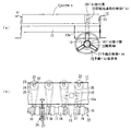
図1は、いわゆるラインドライブローラコンベヤと呼ばれるコンベヤ装置を示し、両側のコンベヤフレーム11を結合させるために所定ピッチで設けられた複数の結合ロッド12にピロー13のベース部13aがそれぞれ固定され、これらのピロー13により駆動軸14が回転自在に保持されている。この駆動軸14は、軸本体部15の軸方向に沿って複数のベルト掛け部としてのシーブ16と、各シーブ16間に所望の距離を確保するためのカラー17とを交互に嵌着して一体化したものである。
FIG. 1 shows a conveyor device called a so-called line drive roller conveyor, in which
この駆動軸14の各シーブ16上で駆動軸14と交差する方向に配置された複数のキャリヤローラ21が、それぞれコンベヤフレーム11の切欠溝22に着脱自在に嵌着された軸部23を介し、コンベヤフレーム11に回転自在に軸支されている。これらのキャリヤローラ21は、各シーブ16上にベルト掛け溝24をそれぞれ有し、駆動軸14の各シーブ16と各キャリヤローラ21のベルト掛け溝24とに回転伝達用の無端ベルトとしての丸ベルト25が90°捩じられて巻掛けられている。
A plurality of
駆動軸14の所定のシーブ16,16間に位置するカラー17にて駆動軸14に対して直角に予備ベルト装着体26が取付けられ、この予備ベルト装着体26を介して駆動軸回りに予備の無端ベルトとしての丸ベルト27が装着されている。
A spare
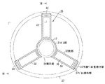
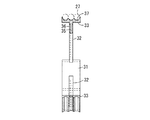
図2および図3に示されるように、予備ベルト装着体26は、駆動軸14のカラー17に嵌着される弾性を有するボス部31と、このボス部31より径方向に突出された3つの腕部32と、これらの腕部32の先端部に設けられた予備ベルト巻掛け部33とを具備した樹脂成形品である。
As shown in FIG. 2 and FIG. 3, the spare
ボス部31は、駆動軸14のカラー17の外径とほぼ同径の内径を有する薄肉幅広の弾性環状体であり、駆動軸14のカラー17の外径より小さく切欠形成された開口部34を有し、この開口部34を経てカラー17に嵌着される。
The
各腕部32は、薄板部35の周囲にリブ36を一体成形して強度を確保している。各予備ベルト巻掛け部33は、各腕部32の先端部にボス部31と同幅に一体成形され、外周面側に3つの予備の丸ベルト27を巻掛けるための3条のベルト保持部としての溝37を有している。
Each
次に、この実施の形態の作用効果を説明する。 Next, the function and effect of this embodiment will be described.
予備ベルト装着体26の弾性を有する薄肉幅広のボス部31は、駆動軸14のカラー17の外径より小さな開口部34を有するので、この開口部34よりカラー17に押付けてワンタッチで嵌込むように嵌着する。このとき、ボス部31は、開口部34がいったんカラー17の外径まで拡大した後、自身の弾性で収縮してカラー17の周面と一体的に密着する。
The thin and
さらに、複数の腕部32の先端部に設けられた予備ベルト巻掛け部33の3条の溝37にそれぞれ予備の丸ベルト27を巻掛けることで、3つの予備の丸ベルト27は、図1(b)の左右方向に変形しないので、稼働中の丸ベルト25と干渉することがなく、また、ベルト自身の弾性により弛むこともないので、溝37から外れることもない。
Further, the three
この予備の丸ベルト27を使用済みの丸ベルトと交換するときは、予備ベルト装着体26から外した予備の丸ベルト27の下部をそのまま駆動軸14のシーブ16に掛け、この丸ベルト27の上部を、コンベヤフレーム11から取外したキャリヤローラ21のベルト掛け溝24に掛け、キャリヤローラ21を元に戻す。
When replacing this
このように、駆動軸14のシーブ16,16間にて駆動軸14に取付けられた予備ベルト装着体26により、駆動軸回りに装着された予備の丸ベルト27を、図1(b)の左右方向に倒れることなく一定の姿勢に保持でき、これにより、予備の丸ベルト27と稼働中の丸ベルト25との干渉を防止でき、また、予備の丸ベルト27を従来のパイプ保持用クリップなどでコンベヤフレーム11などに固定する場合は予備の丸ベルト27の倒れを防止するために必要となる固定補助手段も、ここでは不要となり、そのためのコストアップを防止でき、さらに、駆動軸14に予備ベルト装着体26を取付けるので、予備の丸ベルト27をコンベヤフレーム11などに固定する場合のようにコンベヤ構造に応じて固定手段を設計変更する煩わしさを防止でき、標準コンベヤを始めとして様々なコンベヤ装置に適用でき、高い汎用性が得られる。
In this way, the
また、予備ベルト装着体26は駆動軸14に対して直角に取付けられたので、予備ベルト装着体26が駆動軸14とともに回転する場合においても、予備の丸ベルト27の回転に伴なう軸方向のぶれの発生を防止でき、前記ベルト25,27間の干渉防止を確実なものにできる。
Further, since the spare
さらに、予備ベルト装着体26の弾性を有するボス部31を、駆動軸14のカラー17の外径より小さな開口部34を経てこのカラー17にワンタッチで嵌込むようにして容易に嵌着でき、さらに、腕部32の先端部に設けられた予備ベルト巻掛け部33の溝37に予備の丸ベルト27を巻掛けることで、予備ベルト装着体26に対して予備の無端ベルト27を容易に着脱できる。
Further, the
なお、予備ベルト装着体26は、予備ベルト巻掛け部33の溝37を3条にしているが、場合によっては4条以上の多状溝を形成しても良く、溝数が増加しても、各丸ベルト27の変形を防止する機能を保つことができる。
The spare
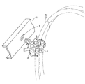
次に、図4は、本発明をカーブコンベヤに適用した他の実施の形態を示す。 Next, FIG. 4 shows another embodiment in which the present invention is applied to a curved conveyor.
この図4に示されたコンベヤ装置は、図1に示されたコンベヤ装置と同様に、複数のベルト掛け部としてのシーブ16を備えた駆動軸14と、この駆動軸14のシーブ16上で駆動軸14と交差する方向に配置されて回転自在に軸支されたベルト掛け溝24を有する複数のテーパ付のキャリヤローラ21と、駆動軸14のシーブ16とキャリヤローラ21のベルト掛け溝24とに巻掛けられた回転伝達用の無端ベルトとしての丸ベルト25と、駆動軸14のシーブ16,16間にて駆動軸14に取付けられた予備ベルト装着体26と、この予備ベルト装着体26を介して駆動軸回りに装着された予備の無端ベルト27とを具備している。
The conveyor apparatus shown in FIG. 4 is driven on a
このカーブコンベヤに用いられた予備ベルト装着体26の構成および作用効果は、図2および図3に示されたものと同一であるから、その説明を省略する。
Since the configuration and operational effects of the spare
14 駆動軸
16 ベルト掛け部としてのシーブ
21 キャリヤローラ
24 ベルト掛け溝
25 回転伝達用の無端ベルトとしての丸ベルト
26 予備ベルト装着体
27 予備の無端ベルトとしての丸ベルト
31 ボス部
32 腕部
33 予備ベルト巻掛け部
34 開口部
37 ベルト保持部としての溝
14 Drive shaft
16 Sheave as belt hook
21 Carrier roller
24 Belt groove
25 Round belt as endless belt for rotation transmission
26 Spare belt wearing body
27 Round belt as spare endless belt
31 Boss
32 arms
33 Spare belt winding part
34 opening
37 Groove as belt holder
Claims (3)
この駆動軸のベルト掛け部上で駆動軸と交差する方向に配置されて回転自在に軸支されたベルト掛け溝を有する複数のキャリヤローラと、
駆動軸のベルト掛け部とキャリヤローラのベルト掛け溝とに巻掛けられた回転伝達用の無端ベルトと、
駆動軸のベルト掛け部間にて駆動軸に取付けられた予備ベルト装着体と、
この予備ベルト装着体を介して駆動軸回りに装着された予備の無端ベルトと
を具備したことを特徴とするコンベヤ装置。 A drive shaft provided with a plurality of belt hanging portions along the axial direction;
A plurality of carrier rollers having belt-hanging grooves which are arranged in a direction intersecting with the drive shaft on the belt-hanging portion of the drive shaft and rotatably supported by the shaft;
An endless belt for rotation transmission wound around the belt hooking portion of the drive shaft and the belt hooking groove of the carrier roller;
A spare belt mounting body attached to the drive shaft between the belt hanging portions of the drive shaft;
And a spare endless belt mounted around the drive shaft via the spare belt mounting body.
ことを特徴とする請求項1記載のコンベヤ装置。 The conveyor apparatus according to claim 1, wherein the spare belt mounting body is attached at a right angle to the drive shaft.
駆動軸の外径より小さく切欠形成された開口部を経て駆動軸に嵌着される弾性を有するボス部と、
ボス部より径方向に突出された腕部と、
腕部の先端部に設けられ予備の無端ベルトを巻掛けるベルト保持部を有する予備ベルト巻掛け部と
を具備したことを特徴とする請求項1または2記載のコンベヤ装置。 Spare belt wearing body,
A boss portion having elasticity to be fitted to the drive shaft through an opening formed in a notch smaller than the outer diameter of the drive shaft;
An arm that protrudes radially from the boss,
The conveyor apparatus according to claim 1, further comprising: a spare belt winding portion provided at a tip portion of the arm portion and having a belt holding portion around which a spare endless belt is wound.
Priority Applications (1)
| Application Number | Priority Date | Filing Date | Title |
|---|---|---|---|
| JP2003332139A JP4247828B2 (en) | 2003-09-24 | 2003-09-24 | Conveyor equipment |
Applications Claiming Priority (1)
| Application Number | Priority Date | Filing Date | Title |
|---|---|---|---|
| JP2003332139A JP4247828B2 (en) | 2003-09-24 | 2003-09-24 | Conveyor equipment |
Publications (2)
| Publication Number | Publication Date |
|---|---|
| JP2005096922A JP2005096922A (en) | 2005-04-14 |
| JP4247828B2 true JP4247828B2 (en) | 2009-04-02 |
Family
ID=34460573
Family Applications (1)
| Application Number | Title | Priority Date | Filing Date |
|---|---|---|---|
| JP2003332139A Expired - Lifetime JP4247828B2 (en) | 2003-09-24 | 2003-09-24 | Conveyor equipment |
Country Status (1)
| Country | Link |
|---|---|
| JP (1) | JP4247828B2 (en) |
Cited By (1)
| Publication number | Priority date | Publication date | Assignee | Title |
|---|---|---|---|---|
| CN103586975A (en) * | 2013-11-14 | 2014-02-19 | 西南石油大学 | Steel reinforcement cage sleeving device suitable for ocean pipeline balance weight production line |
Families Citing this family (2)
| Publication number | Priority date | Publication date | Assignee | Title |
|---|---|---|---|---|
| JP2009203044A (en) * | 2008-02-29 | 2009-09-10 | Daifuku Co Ltd | Roller conveyor facility |
| JP2012218893A (en) * | 2011-04-11 | 2012-11-12 | Daifuku Co Ltd | Belt holder and method for holding belt |
-
2003
- 2003-09-24 JP JP2003332139A patent/JP4247828B2/en not_active Expired - Lifetime
Cited By (1)
| Publication number | Priority date | Publication date | Assignee | Title |
|---|---|---|---|---|
| CN103586975A (en) * | 2013-11-14 | 2014-02-19 | 西南石油大学 | Steel reinforcement cage sleeving device suitable for ocean pipeline balance weight production line |
Also Published As
| Publication number | Publication date |
|---|---|
| JP2005096922A (en) | 2005-04-14 |
Similar Documents
| Publication | Publication Date | Title |
|---|---|---|
| JP4444907B2 (en) | Belt mounting jig | |
| US9930794B2 (en) | Flexible apparatus and electronic device | |
| US7192018B2 (en) | Tiltable-rotatable circular-table device for machine tool | |
| JP4091002B2 (en) | Belt tensioning device | |
| JP2010249312A (en) | Belt installation tool and method of installing belt by using the same | |
| US5441458A (en) | Grooved roller chain idler | |
| JP3669694B2 (en) | Cable drag chain | |
| JP4247828B2 (en) | Conveyor equipment | |
| JP2005030546A (en) | Idler device for power transmission flat belt | |
| CN101137851B (en) | An apparatus for supporting a rotating shaft | |
| JP2005076851A (en) | Chain for power transmission | |
| WO2014010330A1 (en) | Belt attachment jig | |
| JP2008088777A (en) | Window regulator | |
| JP2835698B2 (en) | Conveyor equipment | |
| KR101227356B1 (en) | Carrier roller and carrier device using the same | |
| CN107572311B (en) | Guide bracket | |
| JP2007197149A (en) | Extended belt conveyor | |
| CN217814818U (en) | Belt tension adjusting device | |
| JP6150272B2 (en) | Conveyor device and roller mounting method | |
| JP3629585B2 (en) | Mounting structure of bottle holder of washing machine | |
| JPH0351114Y2 (en) | ||
| JP2008285312A (en) | Flat belt conveying device | |
| JP2006306594A (en) | Conveying belt and belt conveyor | |
| KR100754999B1 (en) | Structure for internal wire of industrial shelf type robot arm | |
| JPH0142685Y2 (en) |
Legal Events
| Date | Code | Title | Description |
|---|---|---|---|
| A621 | Written request for application examination |
Free format text: JAPANESE INTERMEDIATE CODE: A621 Effective date: 20060509 |
|
| A977 | Report on retrieval |
Free format text: JAPANESE INTERMEDIATE CODE: A971007 Effective date: 20081205 |
|
| TRDD | Decision of grant or rejection written | ||
| A01 | Written decision to grant a patent or to grant a registration (utility model) |
Free format text: JAPANESE INTERMEDIATE CODE: A01 Effective date: 20090107 |
|
| A01 | Written decision to grant a patent or to grant a registration (utility model) |
Free format text: JAPANESE INTERMEDIATE CODE: A01 |
|
| A61 | First payment of annual fees (during grant procedure) |
Free format text: JAPANESE INTERMEDIATE CODE: A61 Effective date: 20090107 |
|
| FPAY | Renewal fee payment (event date is renewal date of database) |
Free format text: PAYMENT UNTIL: 20120123 Year of fee payment: 3 |
|
| R150 | Certificate of patent or registration of utility model |
Free format text: JAPANESE INTERMEDIATE CODE: R150 Ref document number: 4247828 Country of ref document: JP Free format text: JAPANESE INTERMEDIATE CODE: R150 |
|
| FPAY | Renewal fee payment (event date is renewal date of database) |
Free format text: PAYMENT UNTIL: 20130123 Year of fee payment: 4 |
|
| R250 | Receipt of annual fees |
Free format text: JAPANESE INTERMEDIATE CODE: R250 |
|
| FPAY | Renewal fee payment (event date is renewal date of database) |
Free format text: PAYMENT UNTIL: 20130123 Year of fee payment: 4 |
|
| R250 | Receipt of annual fees |
Free format text: JAPANESE INTERMEDIATE CODE: R250 |
|
| R250 | Receipt of annual fees |
Free format text: JAPANESE INTERMEDIATE CODE: R250 |
|
| R250 | Receipt of annual fees |
Free format text: JAPANESE INTERMEDIATE CODE: R250 |
|
| R250 | Receipt of annual fees |
Free format text: JAPANESE INTERMEDIATE CODE: R250 |
|
| R250 | Receipt of annual fees |
Free format text: JAPANESE INTERMEDIATE CODE: R250 |
|
| R250 | Receipt of annual fees |
Free format text: JAPANESE INTERMEDIATE CODE: R250 |
|
| R250 | Receipt of annual fees |
Free format text: JAPANESE INTERMEDIATE CODE: R250 |
|
| R250 | Receipt of annual fees |
Free format text: JAPANESE INTERMEDIATE CODE: R250 |
|
| R250 | Receipt of annual fees |
Free format text: JAPANESE INTERMEDIATE CODE: R250 |
|
| R250 | Receipt of annual fees |
Free format text: JAPANESE INTERMEDIATE CODE: R250 |
|
| R250 | Receipt of annual fees |
Free format text: JAPANESE INTERMEDIATE CODE: R250 |
|
| EXPY | Cancellation because of completion of term |