JP4245936B2 - Corrugated cowl for gas turbine engine combustor and method of construction thereof - Google Patents
Corrugated cowl for gas turbine engine combustor and method of construction thereof Download PDFInfo
- Publication number
- JP4245936B2 JP4245936B2 JP2003050273A JP2003050273A JP4245936B2 JP 4245936 B2 JP4245936 B2 JP 4245936B2 JP 2003050273 A JP2003050273 A JP 2003050273A JP 2003050273 A JP2003050273 A JP 2003050273A JP 4245936 B2 JP4245936 B2 JP 4245936B2
- Authority
- JP
- Japan
- Prior art keywords
- cowl
- gas turbine
- turbine engine
- combustor
- annular
- Prior art date
- Legal status (The legal status is an assumption and is not a legal conclusion. Google has not performed a legal analysis and makes no representation as to the accuracy of the status listed.)
- Expired - Fee Related
Links
- 238000000034 method Methods 0.000 title claims description 5
- 238000010276 construction Methods 0.000 title 1
- 238000002485 combustion reaction Methods 0.000 claims description 14
- 239000002184 metal Substances 0.000 claims description 12
- 229910052751 metal Inorganic materials 0.000 claims description 12
- 238000011144 upstream manufacturing Methods 0.000 claims description 9
- 230000033001 locomotion Effects 0.000 claims 1
- 238000004804 winding Methods 0.000 description 9
- 239000000446 fuel Substances 0.000 description 7
- PXHVJJICTQNCMI-UHFFFAOYSA-N Nickel Chemical compound [Ni] PXHVJJICTQNCMI-UHFFFAOYSA-N 0.000 description 4
- 229910000531 Co alloy Inorganic materials 0.000 description 2
- 239000011825 aerospace material Substances 0.000 description 2
- 229910045601 alloy Inorganic materials 0.000 description 2
- 239000000956 alloy Substances 0.000 description 2
- 239000000463 material Substances 0.000 description 2
- 238000012986 modification Methods 0.000 description 2
- 230000004048 modification Effects 0.000 description 2
- 229910052759 nickel Inorganic materials 0.000 description 2
- 239000007787 solid Substances 0.000 description 2
- 230000015572 biosynthetic process Effects 0.000 description 1
- 238000005266 casting Methods 0.000 description 1
- 239000012141 concentrate Substances 0.000 description 1
- 238000005336 cracking Methods 0.000 description 1
- 230000007812 deficiency Effects 0.000 description 1
- 230000000694 effects Effects 0.000 description 1
- 230000007613 environmental effect Effects 0.000 description 1
- 239000012634 fragment Substances 0.000 description 1
- 239000007769 metal material Substances 0.000 description 1
- 238000011084 recovery Methods 0.000 description 1
- 230000001105 regulatory effect Effects 0.000 description 1
- 238000003466 welding Methods 0.000 description 1
Images


Classifications
-
- F—MECHANICAL ENGINEERING; LIGHTING; HEATING; WEAPONS; BLASTING
- F23—COMBUSTION APPARATUS; COMBUSTION PROCESSES
- F23R—GENERATING COMBUSTION PRODUCTS OF HIGH PRESSURE OR HIGH VELOCITY, e.g. GAS-TURBINE COMBUSTION CHAMBERS
- F23R3/00—Continuous combustion chambers using liquid or gaseous fuel
- F23R3/02—Continuous combustion chambers using liquid or gaseous fuel characterised by the air-flow or gas-flow configuration
- F23R3/04—Air inlet arrangements
Landscapes
- Engineering & Computer Science (AREA)
- Chemical & Material Sciences (AREA)
- Combustion & Propulsion (AREA)
- Mechanical Engineering (AREA)
- General Engineering & Computer Science (AREA)
- Turbine Rotor Nozzle Sealing (AREA)
- Structures Of Non-Positive Displacement Pumps (AREA)
- Pre-Mixing And Non-Premixing Gas Burner (AREA)
Description
【0001】
【発明が属する技術分野】
本発明は、ガスタービンエンジンの燃焼器用の波形カウル及びその構成方法に関する。
【0002】
【従来の技術】
ガスタービンエンジンでは、圧縮された空気が、燃焼器段から燃焼器に供給され、該燃焼器において空気は燃料と混合され、燃焼室内で燃焼される。燃料/空気ミキサと対応して燃焼器の内側及び外側通路に流入する圧縮空気の量は、一般的に燃料/空気ミキサ及び燃焼器ドームの上流に設置された内側及び外側カウルによって調整されている。このようなカウルは、一般的に、燃焼器ドーム、カウル、及び内側又は外側燃焼器ライナのいずれかを含むボルト継手によって所定の位置に保持されている。従って、ガスタービンエンジンの外側及び内側カウルの両方は、それら全体にわたる圧力の僅かな変化と同時にエンジンにより生じる振動荷重とを受ける。これらの環境要因は、外側カウルに対してより大きな影響をもつが、それでもなお両方のカウルに摩耗を生じ、その結果カウルの寿命を制限する。
【0003】
この問題に対処するのに、従来技術は、一般的に次ぎの解決策のうちの1つを取ってきた。そのうちの第1は、カウルとしてリップ部を備える金属薄板の本体を用いることを含み、該リップ部は、好ましくは金属薄板をダンパワイヤの周にカールさせるか又は巻き付けることによってその前縁に形成されていた。しかしながら、この設計では、ワイヤと巻き部との間の熱的不整合により生じるワイヤと金属薄板本体の境界面に起こる摩擦型の損耗により寿命が制限されることが判明した。より具体的には、熱的不整合は、金属薄板をワイヤの周りで巻き解させ、ワイヤとカウルの間に間隙を生じさせる。その上に、ディフューザ及び/又は燃焼器の音響から出るホワイトノイズが、ワイヤの金属薄板巻き部に対する高サイクル疲労振動荷重を発生する。従って、摩擦と振動とが組合わさって、ワイヤの金属薄板巻き部に対する振とうを発生させ、その結果、カウルの巻き部分にシンニング、割れの発生、遂には金属薄板及びワイヤの破片の脱離を引き起こす。
【0004】
別のカウル設計は、カウルの前縁リップ部を形成する機械加工されたリングを含み、この場合リングは成形された金属薄板本体に溶接されている。このような機械加工されたリングは、カウルに望ましい中実のリップ部を形成するが、該リングの成形された金属薄板本体への円周溶接は、溶接部の内部及びその周りに応力集中を生じさせる。
【0005】
一体構成のカウル設計が、特許文献1に開示されており、この特許には、その前縁に厚さが増大した中実のリップ部を備えて鋳造されたカウルが開示されている。このカウルは、意図した目的には適しているが、金属薄板カウルよりも重くかつより高価になる傾向がある。
【0006】
【特許文献1】
米国特許第5,924,288号
【0007】
【発明が解決しようとする課題】
上述及び他の欠点及び不具合は、波形カウルにより解決又は緩和される。
【0008】
【課題を解決するための手段】
本発明の例示的な実施形態において、ガスタービンエンジンの燃焼器に用いるためのカウルは、環状の波形部を有する本体を含む。別の例示的な実施形態において、ガスタービンエンジンの燃焼器は、ライナを有しかつ燃焼室を形成する中空の本体と、ライナに接合されかつ環状の波形部を有する外側カウルと、ライナに接合された内側カウルとを含む。ガスタービンエンジン燃焼器用のカウルを構成する方法は、カウルの本体に環状の波形部を形成することを含む。
【0009】
【発明の実施の形態】
幾つかの図において同じ要素には同じように番号が付けられている例示的な図面を参照する。
【0010】
ここで図1を参照すると、ガスタービンエンジン内で用いるのに適した単一の環状の燃焼器10が示されている。燃焼器10は、その中に燃焼室12を形成する中空の本体11を含む。中空の本体11は、形状がほぼ環状であり、外側ライナ14、内側ライナ16、及びドーム形にされた端部即ちドーム18を含む。本環状の構成では、中空の本体11のドーム状の端部18は、その周りに円周方向に間隔を置いて配置された公知の設計の複数の空気/燃料ミキサを更に含む。
【0011】
燃焼器10において、外側カウル22が、燃焼室12の上流に設けられかつ外側のボルト継手24で外側ライナ14及びドーム18に取り付けられる。内側カウル26もまた、燃焼室12の上流に設けられかつ内側ボルト継手28で内側ライナ16及びドーム18に取り付けられる。外側及び内側カウル22及び26は、ガスタービンエンジンのディフューザからの圧縮空気の流れをドーム18とそれぞれ外側及び内側ライナ14及び16に隣接して設置された外側及び内側通路30及び32とに適切に向けかつ調整する役目を果たす。外側及び内側カウル22及び26は、燃焼器10と同様に形状が環状であることが図1及び図2から理解されるであろう。燃焼器カウルでは普通のことであるが、外側及び内側カウル22及び26は、カウル中心軸線34に対して軸方向に細長くなっている。
【0012】
外側及び内側カウル22及び26は、両方とも軽量でかつ安価であることが望まれる。このことを実現するためには、外側及び内側カウル22及び26は、金属薄板で作られることが好ましい。外側及び内側カウル22及び26用の金属薄板材料は、コバルト基合金及びニッケル基合金を含むことができる。具体的には、このようなコバルト基合金についての好ましい米国航空宇宙材料仕様書は、AMS5608を含み、又このようなニッケル基合金についての好ましい米国航空宇宙材料仕様書は、AMS5536、AMS5878及びAMS5599を含む。
【0013】
外側カウル22の剛性を増大させるために、外側カウル22は、環状の波形部40を形成するように鋳込まれる。外側カウル22に対する剛性を増大させることによって、外側カウル22の振動数もまた増大する。剛性の増大に対する振動数の増大には比例する相関関係があり、従って剛性を増大させると振動数もまた増大する。外側カウル22の振動数は、該外側カウル22の振動数がエンジンの振動数より高くなる点まで増大されることが望ましい。
【0014】
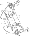
図3を参照すると、別の実施形態において、外側及び内側カウル22及び26の両方が環状の波形部40を有するように形成される。図4及び図5は、環状の波形40部を有する外側及び内側カウル22及び26の斜視図を示す。
【0015】
図6は、外側カウル22に環状の波形部を形成することに対する様々なパラメータを示す。環状の波形部40を鋳込む際に、環状の波形部40に対しては3つのパラメータがある。即ち、(a)「w」で示す、外側カウル22内の環状の波形の数、(b)「h」で示す、各環状の波形40の高さ、及び(c)「s」で示す、各環状の波形40の間隔である。環状の波形部40を形成するための2つの重要なパラメータは、環状の波形40の間隔s及び高さhである。環状の波形の間隔及び高さは、外側カウル22の固有振動数が、エンジン運転範囲外まで増大されるように最適化される。外側カウル22内の波形の数は、外側カウル22の剛性に著しい影響を及ぼすことはない。
【0016】
例示的な実施形態では、環状の波形の間隔は、約0.010インチ(0.254mm)から約0.500インチ(12.7mm)までであり、好ましい間隔は約0.080インチ(2.032mm)である。環状の波形の高さは、約0.010インチ(0.254mm)から約0.050インチ(1.270mm)までであり、好ましい高さは約0.0334インチ(0.848mm)である。上に示した範囲の間隔及び高さを有する環状の波形部を形成することによって、外側カウル22の剛性は、該外側カウル22の振動数が、標準的なエンジン運転範囲外まで増大するように、増大する。
【0017】
図7及び図8は、外側カウル22が全巻き部50(図7)又は半巻き部(図8)を備えるように形成されている、環状の波形を有する外側カウル22を示す。全巻き部50及び半巻き部60は両方とも、外側カウル22の第1の端部62に設置される。第1の端部62は、そこで空気が燃焼器10(図1を参照)に流入する端部である。第1の端部62に全巻き部50又は半巻き部60を設けることによって、空気が燃焼器に流入するときの平滑な表面が得られ、この平滑な表面が空気力学的向上をもたらす。いずれの形式の巻き部も外側カウル22に用いることができるが、半巻き部60を形成する方が外側カウル22の本体の成形が少なくなるので、半巻き部の方が好ましい。
【0018】
環状の波形部40を有する外側カウル22は、所望の時間数の間、高サイクル疲労に屈することなくそれに加わる応力レベルに耐え、かつ燃料/空気ミキサ及び内側/外側通路の要求に一致する状態で空気流を燃焼器に導く。環状の波形部40を有する外側カウル22は、材料、加工及び仕様燃料消費の点から見て軽量でかつ安価である。更に、環状の波形部40を外側カウル22中に組み入れることによって、従来技術のカウルのダンパワイヤ(図示せず)は、排除することができる。また、内側カウル26も、環状の波形部40を有することが可能であり、それが内側カウル26に対して同じ効果をもつことになる。燃焼器10中への所望の空気流量は、実現するのが一般的に難しく、また外側カウル22の設計における少しの変化によっても影響される可能性がある。波形部を外側カウル22中に含む利点は、通路圧力の回復を含む、燃焼器10中への所望の空気流量に対する影響がないと言えるくらい殆どないことである。
【0019】
本発明を、好ましい実施形態に関して説明してきたが、当業者には、本発明の技術的範囲から逸脱することなく様々な変更を行いまた等価な要素を本発明の要素と置き換えることが可能であることは理解されるであろう。更に、本発明の本質的な技術的範囲から逸脱することなく、本発明の教示に合わせて特定の状況又は材料に適応するように多くの変更を行うことが可能である。従って、本発明は、本発明を実施するために考えられる最良の形態として開示した特定の実施形態に限定されるものではなく、また、特許請求の範囲に記載された符号は、理解容易のためであってなんら発明の技術的範囲を実施例に限縮するものではない。
【図面の簡単な説明】
【図1】 内側カウル及び環状の波形部を有する外側カウルを含むガスタービンエンジン燃焼器の縦断面図。
【図2】 図1に示すカウルの前方から後方に見た図。
【図3】 環状の波形部を有する外側カウル及び環状の波形部を有する内側カウルを含むガスタービンエンジン燃焼器の縦断面図。
【図4】 波形外側カウル及び波形内側カウル双方の前方から後方に見た斜視図。
【図5】 図3の波形外側及び内側カウルの後方から前方に見た斜視図。
【図6】 図1に示す波形カウルの拡大部分断面図。
【図7】 全巻き部を備えて示されている、図1に示す波形カウルの拡大部分断面図。
【図8】 半巻き部を備えて示されている、図1に示す波形外側カウルの別の実施形態の拡大部分断面図。
【符号の説明】
10 燃焼器
11 中空の本体
12 燃焼室
14 外側ライナ
16 内側ライナ
18 ドーム
20 空気/燃料ミキサ
22 外側カウル
26 内側カウル
40 環状の波形[0001]
[Technical field to which the invention belongs]
The present invention relates to a corrugated cowl for a combustor of a gas turbine engine and a method for configuring the same.
[0002]
[Prior art]
In a gas turbine engine, compressed air is supplied from a combustor stage to a combustor where the air is mixed with fuel and combusted in a combustion chamber. The amount of compressed air flowing into the combustor's inner and outer passages corresponding to the fuel / air mixer is generally regulated by inner and outer cowls installed upstream of the fuel / air mixer and combustor dome. . Such a cowl is generally held in place by a bolted joint including a combustor dome, a cowl, and either an inner or outer combustor liner. Thus, both the outer and inner cowls of a gas turbine engine are subject to vibration loads generated by the engine simultaneously with slight changes in pressure across them. These environmental factors have a greater impact on the outer cowl, but still cause wear on both cowls, thereby limiting the life of the cowl.
[0003]
To address this problem, the prior art has generally taken one of the following solutions. The first of these includes using a sheet metal body with a lip as a cowl, which is preferably formed at its leading edge by curling or wrapping the sheet metal around the damper wire. It was. However, with this design, it has been found that the lifetime is limited by frictional wear that occurs at the interface between the wire and the sheet metal body caused by thermal mismatch between the wire and the winding. More specifically, the thermal mismatch causes the sheet metal to unwind around the wire and create a gap between the wire and the cowl. In addition, white noise from the diffuser and / or combustor sound generates high cycle fatigue vibration loads on the sheet metal windings of the wire. Therefore, the friction and vibration combine to generate the vibration of the wire around the thin metal sheet winding, and as a result, thinning and cracking occur at the cowl winding, and eventually the thin metal sheet and wire fragments are detached. cause.
[0004]
Another cowl design includes a machined ring that forms the leading edge lip of the cowl, where the ring is welded to the molded sheet metal body. Such machined rings form the solid lip desired for the cowl, but circumferential welding of the ring to the molded sheet metal body concentrates stress in and around the weld. Cause it to occur.
[0005]
A one-piece cowl design is disclosed in U.S. Pat. No. 6,057,086, which discloses a cowl cast with a solid lip portion of increased thickness at the leading edge. This cowl is suitable for the intended purpose, but tends to be heavier and more expensive than the sheet metal cowl.
[0006]
[Patent Document 1]
US Pat. No. 5,924,288
[Problems to be solved by the invention]
The above and other shortcomings and deficiencies are solved or mitigated by corrugated cowls.
[0008]
[Means for Solving the Problems]
In an exemplary embodiment of the invention, a cowl for use in a gas turbine engine combustor includes a body having an annular corrugation. In another exemplary embodiment, a combustor of a gas turbine engine includes a hollow body having a liner and forming a combustion chamber, an outer cowl joined to the liner and having an annular corrugation, and joined to the liner. Including an inner cowl. A method for constructing a cowl for a gas turbine engine combustor includes forming an annular corrugation in the body of the cowl.
[0009]
DETAILED DESCRIPTION OF THE INVENTION
Reference is made to the exemplary drawings in which the same elements in the several views are numbered the same.
[0010]
Referring now to FIG. 1, a single
[0011]
In the
[0012]
Both the outer and
[0013]
In order to increase the rigidity of the
[0014]
Referring to FIG. 3, in another embodiment, both the outer and
[0015]
FIG. 6 shows various parameters for forming an annular corrugation on the
[0016]
In the exemplary embodiment, the spacing of the annular corrugations is from about 0.010 inches (0.254 mm) to about 0.500 inches (12.7 mm), with the preferred spacing being about 0.080 inches (2.032 mm). The height of the annular corrugation is from about 0.010 inches (0.254 mm) to about 0.050 inches (1.270 mm) with a preferred height of about 0.0334 inches (0.848 mm). By forming an annular corrugation having the range and height shown above, the rigidity of the
[0017]
7 and 8 show the
[0018]
The
[0019]
Although the present invention has been described with reference to preferred embodiments, those skilled in the art can make various modifications and replace equivalent elements with elements of the invention without departing from the scope of the invention. It will be understood. In addition, many modifications may be made to adapt a particular situation or material to the teachings of the invention without departing from the essential scope thereof. Accordingly, the invention is not limited to the specific embodiments disclosed as the best mode contemplated for carrying out the invention, and the reference signs in the claims are for ease of understanding. However, the technical scope of the invention is not limited to the embodiments.
[Brief description of the drawings]
FIG. 1 is a longitudinal cross-sectional view of a gas turbine engine combustor including an inner cowl and an outer cowl having an annular corrugation.
FIG. 2 is a view of the cowl shown in FIG. 1 as viewed from the front to the rear.
FIG. 3 is a longitudinal cross-sectional view of a gas turbine engine combustor including an outer cowl having an annular corrugation and an inner cowl having an annular corrugation.
FIG. 4 is a perspective view of the corrugated outer cowl and the corrugated inner cowl as viewed from the front to the rear.
FIG. 5 is a perspective view of the corrugated outer and inner cowls of FIG. 3 as viewed from the rear to the front.
6 is an enlarged partial cross-sectional view of the corrugated cowl shown in FIG.
FIG. 7 is an enlarged partial cross-sectional view of the corrugated cowl shown in FIG. 1, shown with a full turn.
8 is an enlarged partial cross-sectional view of another embodiment of the corrugated outer cowl shown in FIG. 1, shown with a half turn.
[Explanation of symbols]
DESCRIPTION OF
Claims (11)
外側ライナ(14)と内側ライナ(16)とを有しかつ燃焼室(12)を形成する中空の本体(11)と、
前記燃焼室の上流に設けられ、前記外側ライナ(14)に接合された外側カウル(22)と、
前記燃焼室の上流に設けられ、前記内側ライナ(16)に接合された内側カウル(26)と、
を備え、
前記外側カウルには、該外側カウルの固有振動数が前記ガスタービンエンジン運転時の振動数より高くなるよう環状の波形部(40)が複数設けられている
ことを特徴とする燃焼器(10)。A gas turbine engine combustor (10) comprising:
A hollow body (11) having an outer liner (14) and an inner liner (16) and forming a combustion chamber (12);
An outer cowl (22) provided upstream of the combustion chamber and joined to the outer liner (14);
An inner cowl (26) provided upstream of the combustion chamber and joined to the inner liner (16);
With
The combustion characterized in that the outer cowl is provided with a plurality of annular corrugations (40) such that the natural frequency of the outer cowl is higher than the frequency during operation of the gas turbine engine. Vessel (10).
前記外側カウルに、該外側カウルの固有振動数が前記ガスタービンエンジン運転時の振動数より高くなるよう環状の波形部(40)を複数設ける工程を含むことを特徴とする、ガスタービンエンジンの燃焼器を構成する方法。 Combustion of a gas turbine engine comprising the step of providing a plurality of annular corrugations (40) in the outer cowl such that the natural frequency of the outer cowl is higher than the frequency during operation of the gas turbine engine. How to configure the vessel.
Applications Claiming Priority (2)
| Application Number | Priority Date | Filing Date | Title |
|---|---|---|---|
| US10/085,767 US6672067B2 (en) | 2002-02-27 | 2002-02-27 | Corrugated cowl for combustor of a gas turbine engine and method for configuring same |
| US10/085767 | 2002-02-27 |
Publications (3)
| Publication Number | Publication Date |
|---|---|
| JP2003279044A JP2003279044A (en) | 2003-10-02 |
| JP2003279044A5 JP2003279044A5 (en) | 2006-04-06 |
| JP4245936B2 true JP4245936B2 (en) | 2009-04-02 |
Family
ID=27733395
Family Applications (1)
| Application Number | Title | Priority Date | Filing Date |
|---|---|---|---|
| JP2003050273A Expired - Fee Related JP4245936B2 (en) | 2002-02-27 | 2003-02-27 | Corrugated cowl for gas turbine engine combustor and method of construction thereof |
Country Status (5)
| Country | Link |
|---|---|
| US (1) | US6672067B2 (en) |
| EP (1) | EP1340941B1 (en) |
| JP (1) | JP4245936B2 (en) |
| CN (1) | CN1441198B (en) |
| DE (1) | DE60316487T2 (en) |
Families Citing this family (30)
| Publication number | Priority date | Publication date | Assignee | Title |
|---|---|---|---|---|
| WO2007041621A2 (en) * | 2005-10-03 | 2007-04-12 | Xingsheng Sean Ling | Hybridization assisted nanopore sequencing |
| FR2897144B1 (en) * | 2006-02-08 | 2008-05-02 | Snecma Sa | COMBUSTION CHAMBER FOR TURBOMACHINE WITH TANGENTIAL SLOTS |
| FR2897145B1 (en) * | 2006-02-08 | 2013-01-18 | Snecma | ANNULAR COMBUSTION CHAMBER FOR TURBOMACHINE WITH ALTERNATE FIXINGS. |
| FR2906350B1 (en) * | 2006-09-22 | 2009-03-20 | Snecma Sa | ANNULAR COMBUSTION CHAMBER OF A TURBOMACHINE |
| US7765809B2 (en) * | 2006-11-10 | 2010-08-03 | General Electric Company | Combustor dome and methods of assembling such |
| US7856826B2 (en) * | 2006-11-10 | 2010-12-28 | General Electric Company | Combustor dome mixer retaining means |
| WO2009046094A1 (en) | 2007-10-01 | 2009-04-09 | Nabsys, Inc. | Biopolymer sequencing by hybridization of probes to form ternary complexes and variable range alignment |
| US8013738B2 (en) | 2007-10-04 | 2011-09-06 | Kd Secure, Llc | Hierarchical storage manager (HSM) for intelligent storage of large volumes of data |
| WO2009045218A1 (en) | 2007-10-04 | 2009-04-09 | Donovan John J | A video surveillance, storage, and alerting system having network management, hierarchical data storage, video tip processing, and vehicle plate analysis |
| US8262879B2 (en) * | 2008-09-03 | 2012-09-11 | Nabsys, Inc. | Devices and methods for determining the length of biopolymers and distances between probes bound thereto |
| JP5717634B2 (en) * | 2008-09-03 | 2015-05-13 | ナブシス, インコーポレイテッド | Use of longitudinally displaced nanoscale electrodes for voltage sensing of biomolecules and other analytes in fluid channels |
| US9650668B2 (en) | 2008-09-03 | 2017-05-16 | Nabsys 2.0 Llc | Use of longitudinally displaced nanoscale electrodes for voltage sensing of biomolecules and other analytes in fluidic channels |
| WO2010111605A2 (en) * | 2009-03-27 | 2010-09-30 | Nabsys, Inc. | Devices and methods for analyzing biomolecules and probes bound thereto |
| US8455260B2 (en) * | 2009-03-27 | 2013-06-04 | Massachusetts Institute Of Technology | Tagged-fragment map assembly |
| US8246799B2 (en) * | 2009-05-28 | 2012-08-21 | Nabsys, Inc. | Devices and methods for analyzing biomolecules and probes bound thereto |
| US8715933B2 (en) | 2010-09-27 | 2014-05-06 | Nabsys, Inc. | Assay methods using nicking endonucleases |
| EP2640849B1 (en) | 2010-11-16 | 2016-04-06 | Nabsys 2.0 LLC | Methods for sequencing a biomolecule by detecting relative positions of hybridized probes |
| US11274341B2 (en) | 2011-02-11 | 2022-03-15 | NABsys, 2.0 LLC | Assay methods using DNA binding proteins |
| WO2014024944A1 (en) | 2012-08-07 | 2014-02-13 | 日野自動車 株式会社 | Burner for exhaust gas purification devices |
| EP2843306A4 (en) | 2012-08-07 | 2015-12-02 | Hino Motors Ltd | Burner for exhaust gas purification devices |
| EP2884174B1 (en) | 2012-08-07 | 2018-03-21 | Hino Motors, Ltd. | Burner |
| EP2884175A4 (en) | 2012-08-13 | 2015-10-21 | Hino Motors Ltd | Burner |
| US9914966B1 (en) | 2012-12-20 | 2018-03-13 | Nabsys 2.0 Llc | Apparatus and methods for analysis of biomolecules using high frequency alternating current excitation |
| EP2956550B1 (en) | 2013-01-18 | 2020-04-08 | Nabsys 2.0 LLC | Enhanced probe binding |
| DE102014213302A1 (en) | 2014-07-09 | 2016-01-14 | Rolls-Royce Deutschland Ltd & Co Kg | Combustion chamber of a gas turbine with screwed combustion chamber head |
| US10094332B2 (en) | 2014-09-03 | 2018-10-09 | The Boeing Company | Core cowl for a turbofan engine |
| EP3051206B1 (en) * | 2015-01-28 | 2019-10-30 | Ansaldo Energia Switzerland AG | Sequential gas turbine combustor arrangement with a mixer and a damper |
| DE102015213629A1 (en) | 2015-07-20 | 2017-01-26 | Rolls-Royce Deutschland Ltd & Co Kg | Cover member and combustion chamber assembly for a gas turbine |
| US10228136B2 (en) * | 2016-02-25 | 2019-03-12 | General Electric Company | Combustor assembly |
| US10982852B2 (en) | 2018-11-05 | 2021-04-20 | Rolls-Royce Corporation | Cowl integration to combustor wall |
Family Cites Families (11)
| Publication number | Priority date | Publication date | Assignee | Title |
|---|---|---|---|---|
| US3854285A (en) * | 1973-02-26 | 1974-12-17 | Gen Electric | Combustor dome assembly |
| GB1438379A (en) * | 1973-08-16 | 1976-06-03 | Rolls Royce | Cooling arrangement for duct walls |
| GB2039359A (en) * | 1979-01-15 | 1980-08-06 | United Technologies Corp | Gas turbine combustion chamber |
| US4606190A (en) * | 1982-07-22 | 1986-08-19 | United Technologies Corporation | Variable area inlet guide vanes |
| US5197290A (en) * | 1990-03-26 | 1993-03-30 | Fuel Systems Textron Inc. | Variable area combustor air swirler |
| CA2056592A1 (en) * | 1990-12-21 | 1992-06-22 | Phillip D. Napoli | Multi-hole film cooled combustor liner with slotted film starter |
| US5181377A (en) * | 1991-04-16 | 1993-01-26 | General Electric Company | Damped combustor cowl structure |
| US5924288A (en) * | 1994-12-22 | 1999-07-20 | General Electric Company | One-piece combustor cowl |
| US6212870B1 (en) * | 1998-09-22 | 2001-04-10 | General Electric Company | Self fixturing combustor dome assembly |
| US6148600A (en) | 1999-02-26 | 2000-11-21 | General Electric Company | One-piece sheet metal cowl for combustor of a gas turbine engine and method of configuring same |
| US6438958B1 (en) * | 2000-02-28 | 2002-08-27 | General Electric Company | Apparatus for reducing heat load in combustor panels |
-
2002
- 2002-02-27 US US10/085,767 patent/US6672067B2/en not_active Expired - Fee Related
-
2003
- 2003-02-25 EP EP03251118A patent/EP1340941B1/en not_active Expired - Lifetime
- 2003-02-25 DE DE60316487T patent/DE60316487T2/en not_active Expired - Lifetime
- 2003-02-27 JP JP2003050273A patent/JP4245936B2/en not_active Expired - Fee Related
- 2003-02-27 CN CN03106639.9A patent/CN1441198B/en not_active Expired - Fee Related
Also Published As
| Publication number | Publication date |
|---|---|
| US20030159445A1 (en) | 2003-08-28 |
| DE60316487D1 (en) | 2007-11-08 |
| EP1340941B1 (en) | 2007-09-26 |
| JP2003279044A (en) | 2003-10-02 |
| CN1441198B (en) | 2010-05-26 |
| EP1340941A3 (en) | 2004-06-09 |
| EP1340941A2 (en) | 2003-09-03 |
| US6672067B2 (en) | 2004-01-06 |
| CN1441198A (en) | 2003-09-10 |
| DE60316487T2 (en) | 2008-05-21 |
Similar Documents
| Publication | Publication Date | Title |
|---|---|---|
| JP4245936B2 (en) | Corrugated cowl for gas turbine engine combustor and method of construction thereof | |
| US5924288A (en) | One-piece combustor cowl | |
| JP4256709B2 (en) | Annular integrated corrugated liner for gas turbine engine combustors. | |
| JP4033715B2 (en) | Exhaust frame, gas turbine engine, and manufacturing method thereof | |
| JP4559796B2 (en) | Combustor dome assembly of a gas turbine engine with a free floating swirler | |
| JP4450564B2 (en) | Structural cover for bolted flanges of gas turbine engines | |
| US8826669B2 (en) | Gas turbine exhaust case | |
| US8256224B2 (en) | Combustion apparatus | |
| JP5530132B2 (en) | Method and apparatus for assembling a gas turbine engine | |
| US6725667B2 (en) | Combustor dome for gas turbine engine | |
| US6148600A (en) | One-piece sheet metal cowl for combustor of a gas turbine engine and method of configuring same | |
| JP5149596B2 (en) | Combustor dome mixer holding means | |
| EP1507121A2 (en) | Combustor dome assembly of a gas turbine engine having improved deflector plates | |
| JP2003014237A (en) | Flanged hollow structure | |
| JP2004085189A5 (en) | ||
| JP2008267799A (en) | Method and device for facilitating reduction of combustor pressure drop | |
| JP2001271607A (en) | Method and device for minimizing temperature gradient in turbine shroud | |
| US6779268B1 (en) | Outer and inner cowl-wire wrap to one piece cowl conversion | |
| JP4370887B2 (en) | Lobe mixer | |
| GB2361302A (en) | Discharge nozzle for a gas turbine engine combustion chamber | |
| JP2019056548A (en) | Non-uniform mixer for combustion dynamics attenuation | |
| US6886343B2 (en) | Methods and apparatus for controlling engine clearance closures | |
| CA3050842A1 (en) | Compressor diffuser with diffuser pipes varying in natural vibration frequencies | |
| JPH04115253U (en) | gas turbine combustor | |
| JPH11141879A (en) | Gas turbine combustor liner structure |
Legal Events
| Date | Code | Title | Description |
|---|---|---|---|
| A521 | Request for written amendment filed |
Free format text: JAPANESE INTERMEDIATE CODE: A523 Effective date: 20060222 |
|
| A621 | Written request for application examination |
Free format text: JAPANESE INTERMEDIATE CODE: A621 Effective date: 20060222 |
|
| A977 | Report on retrieval |
Free format text: JAPANESE INTERMEDIATE CODE: A971007 Effective date: 20080415 |
|
| A131 | Notification of reasons for refusal |
Free format text: JAPANESE INTERMEDIATE CODE: A131 Effective date: 20080422 |
|
| A601 | Written request for extension of time |
Free format text: JAPANESE INTERMEDIATE CODE: A601 Effective date: 20080717 |
|
| A602 | Written permission of extension of time |
Free format text: JAPANESE INTERMEDIATE CODE: A602 Effective date: 20080723 |
|
| A521 | Request for written amendment filed |
Free format text: JAPANESE INTERMEDIATE CODE: A523 Effective date: 20081020 |
|
| TRDD | Decision of grant or rejection written | ||
| A01 | Written decision to grant a patent or to grant a registration (utility model) |
Free format text: JAPANESE INTERMEDIATE CODE: A01 Effective date: 20081209 |
|
| A01 | Written decision to grant a patent or to grant a registration (utility model) |
Free format text: JAPANESE INTERMEDIATE CODE: A01 |
|
| A61 | First payment of annual fees (during grant procedure) |
Free format text: JAPANESE INTERMEDIATE CODE: A61 Effective date: 20090107 |
|
| R150 | Certificate of patent or registration of utility model |
Free format text: JAPANESE INTERMEDIATE CODE: R150 |
|
| FPAY | Renewal fee payment (event date is renewal date of database) |
Free format text: PAYMENT UNTIL: 20120116 Year of fee payment: 3 |
|
| LAPS | Cancellation because of no payment of annual fees |