JP4245662B2 - Method and apparatus for software access to a microprocessor serial number - Google Patents
Method and apparatus for software access to a microprocessor serial number Download PDFInfo
- Publication number
- JP4245662B2 JP4245662B2 JP53463697A JP53463697A JP4245662B2 JP 4245662 B2 JP4245662 B2 JP 4245662B2 JP 53463697 A JP53463697 A JP 53463697A JP 53463697 A JP53463697 A JP 53463697A JP 4245662 B2 JP4245662 B2 JP 4245662B2
- Authority
- JP
- Japan
- Prior art keywords
- serial number
- encrypted
- microprocessor
- key
- encryption key
- Prior art date
- Legal status (The legal status is an assumption and is not a legal conclusion. Google has not performed a legal analysis and makes no representation as to the accuracy of the status listed.)
- Expired - Fee Related
Links
Images


Classifications
-
- G—PHYSICS
- G06—COMPUTING; CALCULATING OR COUNTING
- G06F—ELECTRIC DIGITAL DATA PROCESSING
- G06F21/00—Security arrangements for protecting computers, components thereof, programs or data against unauthorised activity
- G06F21/70—Protecting specific internal or peripheral components, in which the protection of a component leads to protection of the entire computer
- G06F21/71—Protecting specific internal or peripheral components, in which the protection of a component leads to protection of the entire computer to assure secure computing or processing of information
- G06F21/73—Protecting specific internal or peripheral components, in which the protection of a component leads to protection of the entire computer to assure secure computing or processing of information by creating or determining hardware identification, e.g. serial numbers
-
- G—PHYSICS
- G06—COMPUTING; CALCULATING OR COUNTING
- G06F—ELECTRIC DIGITAL DATA PROCESSING
- G06F11/00—Error detection; Error correction; Monitoring
- G06F11/006—Identification
-
- G—PHYSICS
- G06—COMPUTING; CALCULATING OR COUNTING
- G06F—ELECTRIC DIGITAL DATA PROCESSING
- G06F12/00—Accessing, addressing or allocating within memory systems or architectures
- G06F12/14—Protection against unauthorised use of memory or access to memory
- G06F12/1408—Protection against unauthorised use of memory or access to memory by using cryptography
-
- G—PHYSICS
- G06—COMPUTING; CALCULATING OR COUNTING
- G06F—ELECTRIC DIGITAL DATA PROCESSING
- G06F2207/00—Indexing scheme relating to methods or arrangements for processing data by operating upon the order or content of the data handled
- G06F2207/72—Indexing scheme relating to groups G06F7/72 - G06F7/729
- G06F2207/7219—Countermeasures against side channel or fault attacks
-
- G—PHYSICS
- G06—COMPUTING; CALCULATING OR COUNTING
- G06F—ELECTRIC DIGITAL DATA PROCESSING
- G06F2211/00—Indexing scheme relating to details of data-processing equipment not covered by groups G06F3/00 - G06F13/00
- G06F2211/007—Encryption, En-/decode, En-/decipher, En-/decypher, Scramble, (De-)compress
Landscapes
- Engineering & Computer Science (AREA)
- Theoretical Computer Science (AREA)
- Physics & Mathematics (AREA)
- Computer Hardware Design (AREA)
- General Engineering & Computer Science (AREA)
- General Physics & Mathematics (AREA)
- Mathematical Physics (AREA)
- Computer Security & Cryptography (AREA)
- Software Systems (AREA)
- Quality & Reliability (AREA)
- Storage Device Security (AREA)
Description
発明の分野
この発明はマイクロプロセッサのシリアル番号に対し、より特定的にはマイクロプロセッサのシリアル番号にアクセスするために符号化された暗号キーを用いる方法に関する。
関連技術の説明
長い間、ワークステーション、ミニコンピュータおよびメインフレームの中にはそれらを一意に識別するシリアル番号が埋込まれていた。シリアル番号を付与することで、製造業者が現場の製品の出所を装置の原製造業者(OEM)までたどることができる。このため、製造業者はその製品をよりよく管理することができる。さらに、シリアル番号を提供することで、独立したソフトウェアベンダーが製品を登録することが可能となる。マイクロプロセッサおよびパーソナルコンピュータは典型的には今までシリアル番号によって追跡されていなかったが、これは幾分かはシリアル番号を記憶し、および/または読出すための回路を設ける費用が加算されるためであった。
しかしながら、マイクロプロセッサそのものがさらに複雑になってきたため、シリアル番号を提供するための回路および/またはプロセスステップを追加する費用対効果はますます高くなりつつある。さらに、シリアル番号は特定のソフトウェアに関連づけることができる。つまり、たとえば、特定のプロセッサにインストールされているソフトウェアはパスワードを読み、その後その特定のマイクロプロセッサに合わせられるため、そのソフトウェアを別のプロセッサにインストールしようと試みても失敗する。とはいえ、コンピュータシステムにおいてシリアル番号識別をもたらす標準的な方法は一般的に費用がかかる。競争の激しいマイクロプロセッサ市場ではこのようなコストは最小に抑えることが望ましい。したがって、現場の製品の出所を装置の原製造業者(OEM)までたどるため、マイクロプロセッサにシリアル番号を提供する安価で効果的な方法が必要である。
マイクロプロセッサのシリアル番号を機械可読な形態で提供することにおける問題は、権限のないユーザによりアクセスされ、そのため権限のない変更を受けることがあり得ることである。したがって、機械可読であるシリアル番号への権限のないアクセスを防ぐための機構が必要である。
マイクロプロセッサのシリアル番号を提供しソフトウェアにシリアル番号を付けることに関する別の問題は、プロセッサがアップグレードされるとか何らかの方法で置換えられる場合、そのソフトウェアが機能しなくなることである。(ソフトウェアにシリアル番号を付けるとは、ここではCPUシリアル番号を所与のソフトウェアのセットに与えることと定義される。ソフトウェアはそのシリアル番号を有さないプロセッサでは動作することができない。)しかしながら、ソフトウェアにとって、権限のないコンピュータシステムにロードされることと権限のないプロセッサを提供されることとに大した差はない。いずれの場合にも、ソフトウェアはもはや存在しないプロセッサに合わせられていることとなり、動作しない。したがって、シリアル番号を付けられたソフトウェアが権限のないプロセッサで動作していることを検出し、これに応答して権限再付与プロセスを開始できるようなアップグレード方法が必要である。権限再付与プロセスが成功すると、ソフトウェアはアップグレードされたプロセッサで機能する。しかしながら、権限再付与プロセスに失敗するということは、ソフトウェアそのものが権限のないシステムにロードされること、したがって機能しないことを意味する。
上述のとおり、ソフトウェアにシリアル番号を付けることもまた望ましい。しかしながら、そうするには、シリアル番号が権限のない変更によってアクセスできない状態を保つと同時に、ソフトウェアによってシリアル番号にアクセスする簡単な方法をもたらすことが望ましい。
そのため、この発明では、ソフトウェアがマイクロプロセッサのシリアル番号およびその暗号キーを読出しかつアクセスすることを可能にする。さらに、キーを符号化して偶然にユーザにキーが知れるのを防ぐための機構が提供される。
発明の概要
したがって、マイクロプロセッサのシリアル番号へのアクセスをもたらすための独特のシステムおよび方法が提供される。プロセッサと同じ装置パッケージ内に形成される不揮発性ランダムアクセスメモリにマイクロプロセッサのシリアル番号を記憶するための機構が提供される。マイクロプロセッサのシリアル番号は権限のないアクセスおよび変更を防ぐため、二重キー暗号化方式を用いて暗号化される。暗号キー自体も符号化され、権限のあるユーザにはたやすくアクセスできるが、シリアル番号が権限なく読まれることを防ぐ。最後に、特定のプロセッサのシリアル番号を関連付けられたソフトウェアが権限のないプロセッサにおいて動作していることを検出し権限の再付与を求めることができる方法が提供される。
そのため、この発明では、ソフトウェアがマイクロプロセッサのシリアル番号およびその暗号キーを読出しかつアクセスすることを可能にする。さらに、キーを符号化して偶然にユーザにキーが知れるのを防ぐための機構が提供される。
したがって、工場から出荷される前にプログラムできるCPUシリアル番号のための記憶空間を提供するための、CPUダイと共にパッケージされた小さい不揮発性ランダムアクセスメモリが提供される。CPUダイおよび不揮発性RAMダイの双方はパッケージのキャビティ内にある。この2つのダイの接続は従来のワイヤボンディングによりもたらされ、RAMとCPUの間にシリアルインタフェースを設けることによって最小にされる。
この発明の別の局面によれば、CPUシリアル番号を記憶する不揮発性RAMへのアクセスはプロセッサ上の暗号化および論理によって制御される。機構の安全性を高めるため、2つの小さい階層化された暗号キーが用いられる。シリアル番号は両方のキーが正しいときのみ変更できる。キーおよび暗号アルゴリズムは製造業者のみが知っている。80ビットのシリアル番号および2つの32ビットのキーのためのレジスタ領域が提供される。RAMに記憶されるデータ内にチェックサムが含まれており、CPUに対するRAMデータの転送におけるエラーを検出できる。
この発明のさらに別の局面によれば、シリアル番号を付けられたソフトウェアが権限のないプロセッサにおいて動作していることを検出し、権限の再付与のための使用プロファイルに基づいて権限再付与プロセスを開始するアップグレード方法が提供される。権限付与サービスが利用可能でない場合、または許されない場合、一時的にソフトウェアを再使用可とすることができる。問題が解決するまでの間、ユーザの使用が制限される。
この発明のさらに別の局面によれば、シリアル番号を付けられたCPUを検出し、CPUシリアル番号を抽出しこれを標準アプリケーションプログラミングインタフェース(API)によりアプリケーションに提供するためのコードシーケンスが提供される。
広く言えばこの発明は暗号キーが符号化されることで符号化された暗号キーをもたらす方法を企図する。このことはたとえば、複数バイトの暗号キーのバイトを合計することを含んでもよい。暗号キーおよびシリアル番号へのアクセスが望まれる場合、暗号キーのバイトは復号化される。
【図面の簡単な説明】
好ましい実施例の以下の詳細な説明を以下の図面に関連して読まれると、この発明のよりよい理解が得られるであろう。
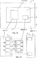
図1aおよび図1bは、この発明の一実施例による装置パッケージを共有する不揮発性RAMダイとCPUダイとを示すブロック図である。
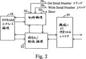
図2はこの発明の一実施例による暗号化システムの一実施例のブロック図である。
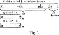
図3はこの発明の一実施例によるレジスタセット暗号化システムの図である。
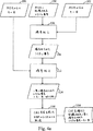
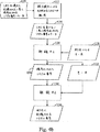
図4a、図4bおよび図4cはこの発明の一実施例による暗号化の書込読取およびアンロックプロセスを示すフローチャートの図である。
図5はこの発明の一実施例によるアップグレード権限再付与システムを示すフローチャートの図である。
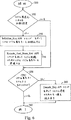
図6はこの発明の一実施例によるシリアル番号へのアクセスを示すフローチャートの図である。
図7はこの発明の一実施例による暗号化を示す図である。
この発明はさまざまな変更および代替の形態が可能であるが、その特定の実施例は例として図示され、ここで詳しく説明される。しかしながら、図面およびその詳細な説明によってこの発明を開示される特定の形態に限定することを意図するものではなく、逆にこの発明が添付の請求の範囲により規定されるこの発明の精神および範囲内に従うあらゆる変更、均等物および代替例を包含するものであることが理解されるべきである。
好ましい実施例の詳細な説明
図1aを参照すると、中央処理装置(CPU)ダイ6、不揮発性ランダムアクセスメモリ(NVRAM)ダイ8、ダイキャビティ4および装置パッケージ10を含む集積回路パッケージ2の図が示される。好ましい実施例では、NVRAMダイ8はCPUダイ6とは別に形成される。図1bを参照すると、NVRAMダイ8は信号線14a、14b、14cによりCPUダイ6に結合される。信号線14a、14bおよび14cはそれぞれ、ボンディングパッド12a、12b、12cおよび16a、16b、16cによりCPUダイ6とNVRAMダイ8とに装着される。ある実施例では、信号線14aは送信線であり、信号線14bは受信線である。信号線14cはクロック線であり、NVRAMとCPUとの間でシリアルインタフェースを形成する。別の実施例では、NVRAMダイ8は1本の伝送線によってCPUダイ6に接続されてもよい。その実施例では、CPUおよびNVRAMはシリアルインタフェースをもたらすためさらなる回路を含む。NVRAMには工場から出荷される前にCPUシリアル番号がプログラムされる。
CPUダイと共にパッケージされるNVRAM内にCPUシリアル番号を与えることは、たとえばシリアル番号をダイに永久的にエッチングすることと比べてコストの面で有利であるが、シリアル番号への権限のないアクセスを防ぐための機構が必要である。NVRAMへのアクセス、よってシリアル番号へのアクセスはプロセッサ面の暗号キーおよび論理を介して制御される。次に図2を参照すると、例示的な暗号化機構のブロック図が示される。CPUは、制御論理20および暗号化/解読論理22に結合されるNVRAMインタフェース論理18を含む。制御論理20および暗号化/解読論理22はさらに互いに結合される。制御論理20はシリアル番号読取、書込プロセスを監督する。暗号化/解読論理22は以下に説明されるようにシリアル番号の暗号化および解読を行なう。暗号化/解読論理22はまた、機械またはモデルにより特定されるレジスタ24に結合される。機械により特定されるレジスタ24はプログラマにインタフェースを提供し、最近のx86タイププロセッサに共通のタイプのものであり、コマンドおよび/または状態ビット(たとえばアンロック、読出しなど)を含む。しかしながら、他のプロセッサまたはレジスタの使用も考えられることに注意されたい。制御論理20はさらにGet Serial Numberコマンド線26、Write Serial Numberコマンド線28およびError線30に結合される。NVRAMインタフェース論理18はNVRAMに対する転送を制御する。
図3は80ビットのシリアル番号32、32ビットのキーA36、および32ビットのキーB38を示す。80ビットのシリアル番号32およびキー36、38は機械により特定されるレジスタ24内に記憶される。16ビットのチェックサム34はさらにNVRAMに記憶されるデータ内に含まれ、CPUに対するデータの転送におけるエラーの検出を可能にする。しかしながら、チェックサム34は暗号化プロセスには用いられない。機構の安全性を高めるため、2つのキー36、38を使用した階層化された暗号化方法が用いられる。シリアル番号そのものはキー36、38の双方が正しい場合のみ変更できる。キーおよび暗号アルゴリズムは製造業者のみが知っている。
次に図4aを参照すると、新しいシリアル番号を書くのに用いられる書込プログラムのフローチャートの図が示される。はじめに、シリアル番号が機械により特定されるレジスタ(MSR)24内に提供され(ステップ100)、キー36、38も同様にされる(ステップ104、ステップ102)。次に、ステップ106において、機械により特定されるレジスタ24内に記憶されるシリアル番号にキー38を用いて第1レベルの暗号化を施す。暗号化されたシリアル番号(ステップ108)およびキーBは次にステップ112においてキーAを用いてさらに暗号化される。こうして二重に暗号化されたシリアル番号は巡回冗長チェックサム(CRC)とともにステップ114において示される。次に、ステップ116において、暗号化されたキーBを備えた二重に暗号化されたシリアル番号はCRC生成を用いてNVRAMに出力される。ステップ118ではCRCを備えた結果生じる暗号化されたシリアル番号が記憶される。
次に図4bを参照すると、読取プロセスのフローチャートの図が示される。記憶されたCRCを備えた二重に暗号化されたシリアル番号および暗号化されたキーBは、はじめにNVRAM内に記憶される(ステップ120)。ステップ122では、誤り検出を用いてNVRAMからCPUへの転送が起こる。CRCを含まない、結果生じる二重に暗号化されたシリアル番号および暗号化されたキーB(ステップ124)は次にステップ126において機械により特定されるレジスタからのキーA(ステップ128)を用いて解読される。ステップ130においてキーAを用いて解読した結果残るのはキーBにより暗号化されたシリアル番号である(ステップ132)。そこで、暗号化されたシリアル番号をキーBを用いてステップ134において解読する。その結果生じる完全に解読されたシリアル番号は次にステップ136において機械により特定されるレジスタに記憶される。解読プロセスの略図は図7に見られる。キーAが、二重に暗号化されたシリアル番号および暗号化されたキーB123に適用される。結果生じる暗号化されたシリアル番号125が次に、キーBを用いて解読される。結果生じるシリアル番号127が次に、マイクロプロセッサシリアル番号(または機械により特定される)レジスタ24に記憶される。
上述の読取および書込プロセスはCPUがアンロック状態にある場合のみ可能である。これは、初めて新しいシリアル番号をプログラムする際に起こる。たとえば、プロセッサが最初に組立てられる際はNVRAMはオールゼロにされる。プロセッサはこの状態を検出し、アンロック状態に入り、上述の書込方法によって最初のシリアル番号がプログラムされるようにする。しかしながら、その装置が以前にシリアル番号を有していた場合、シリアル番号を再プログラムするために以下に説明するアンロックシーケンスを動作させなければならない。より特定的には、図4cを参照すると、初期状態では、シリアル番号は機械により特定されるレジスタ内に記憶され、キーA、Bもまた同様である(ステップ138、140および142)。シリアル番号は次にステップ144においてキーBを用いて暗号化される。結果生じる暗号化されたシリアル番号(ステップ146)およびキーBはさらにステップ148においてキーAを用いて暗号化される。ステップ150における結果生じる二重に暗号化されたシリアル番号および暗号化されたキーBは次にステップ152においてコンパレータに入力される。同時に、暗号化されたキーBおよびCRCを備えた以前に記憶された二重に暗号化されたシリアル番号(ステップ154)はステップ156において適当な誤り検出を用いてNVRAMからCPUへ転送される。ステップ158では、二重に暗号化されたシリアル番号およびキーBはコンパレータ(ステップ152)へ出力される。ステップ150およびステップ158からの2つの出力はコンパレータ152において比較される。一致が見られると、プロセッサはアンロック状態に入る(ステップ160)。
容易に理解されるように、上述のプロセスは必然的にプロセッサにより特定されるものである。しかしながら、プロセッサはますます容易にアップグレードすることが可能となっている。プロセッサのアップグレードはそのプロセッサのシリアル番号にリンクされるソフトウェア(「シリアル番号を付けられたソフトウェア」)の機能を停止させることになる。この発明の一局面によれば、シリアル番号を付けられたソフトウェアがアップグレードされた(権限のない)プロセッサにおいて動作していることを検出し、権限再付与プロセスを開始できる方法が提供される。好ましい実施例では、権限再付与の手順は一連のアプリケーションプログラミングインタフェース(API)を用いることで実行される。適切なAPIは以下に記述される。
Read_CPU_Serial_Number
この関数により、OSおよびこれを呼ぶアプリケーションがCPUシリアル番号を読むことを可能にできる。ある実施例では、シリアル番号を読むために32ビットのキーを入力するとともに適切なMSR内のread_serial_numberビットをセットしなければならない。
エントリ:
シリアル番号のためにアクセスされるMSR
32ビットのキー
出口:
CPUシリアル番号
Upgrade_CPU_Serial_Number
この関数はCPUアップグレードが起こると自動的にアップグレードおよび権限再付与プロセスを実行する。
エントリ:
新しいシリアル番号
古いシリアル番号
出口:
Authorization==0−付与されず
Authorization==1−アップグレード可
Lock_With_New_CPU_Serial_Number
Upgrade_CPUがAuthorization=1を返した場合、対応するアプリケーションは利用されるソフトウェアロック方式を変更するのに適切な動作を行なう。
エントリ:新しいシリアル番号
出口:Success==1−>新しいシリアル番号でのロックOK
Success==0−>新しいシリアル番号でのロック失敗
Get_Previous_CPU_Serial_Number
この関数は、OSおよびアプリケーションが前のCPUシリアル番号がシステムに記憶したものを取出すための機構を提供する。
エントリ:
なし
出口:
Success==1or0
If Success==1
システムにより記憶される、前のCPUシリアル番号
else
なし
権限付与プロセスは図5に詳述される。その手順はステップ200で開始される。ステップ202では、導入されたマイクロプロセッサの現在のCPUシリアル番号が上述のRead_CPU_Serial_NumberAPIコマンドを介して読まれる。次のステップ204では、最も新しく記憶されたシリアル番号がGet_Previous_CPU_Serial_NumberAPIコマンドを介して取出される。現在のCPUシリアル番号が前のCPUシリアル番号と同じである場合(ステップ206)、プロセスはステップ208で終了する。しかしながら、その2つが等しくない場合、ステップ210においてUpgrade_CPU_Serial_NumberAPIコマンドが開始され権限付与が求められる。権限付与は、電話音声、データ、インターネット接続211または他の遠隔接続を介してベンダーと連絡を取ることにより得られる。権限付与のための使用プロファイルに基づいて、ステップ212においてソフトウェアを再使用可とすることができる。権限付与が可能である場合、ステップ214において、新しいCPUシリアル番号およびLock_with_new_CPU_serial_numberAPIコマンドを用いてソフトウェアロックが行なわれる(ステップ214)。権限付与が可能でない場合、ステップ216においてアップグレードはできない。いずれの場合にも、プロセスはステップ208において完了する。権限付与サービスルーチンが利用可能でない場合、または権限付与が拒否される場合、一実施例では制限される使用を可能とするためのAPIが想定されており、ユーザがその問題が解決するまでこのシステムを使用できるようにする。
上述の暗号化機構における可能性のある隙の1つは、32ビットのキーAおよび32ビットのキーBが機械により特定されるレジスタに記憶されることである。シリアル番号を書込むには両方のキーが必要であるが、これを読むには一方のみを提示すればよい。したがって、キー値を取出そうとするユーザから守るため、シリアル番号を読むのに必要なキー値を符号化しなければならない。また、CMOSを保存するためには、キーのデータサイズを4バイトから1バイトまたは2バイトに減少することが望ましい。この発明のこの局面は図6および以下に説明するAPIに関連して最もよく説明される。
Initialize_Key
この関数はシステム製造元によってのみ開始され得る。この関数の目的は32ビットのキー値をCMOSに記憶することを容易にすることである。この機能はキーを符号化しCMOSに記憶する。
エントリ:
32ビットのキー値
符号化された値の記憶のためのCMOSインデックス
出口:
なし
Encode_And_Store_Key
この関数はInitialize_Key関数によって呼ばれる。この関数はキーを符号化してこれをシステムCMOSに記憶する。キーは100%保護されるわけではないが、通常のユーザがキー情報をシステムCMOSメモリから復号化することを防ぐ。
エントリ:
32ビットのキー値
符号化された値の記憶のためのCMOSインデックス
出口:
なし
Decode_Key
この関数はCMOSから符号化されたキー値を取出しこれを使用するため復号化する。
エントリ:
記憶された符号化されたキー値のためのCMOSインデックス
出口:
32ビットのキー値
以下の図ではシリアル番号およびキーのシステムソフトウェアアクセスおよび制御を示す。
より特定的には、図6を参照するとシリアル番号キーの符号化はステップ250で開始する。システム製造元がキーを初期設定しようとしていた場合(ステップ252)シリアル番号キーを初期設定するためにInitialize_KeyAPIコマンドがアサートされる(ステップ254)。初期設定の際、CPUシリアル番号キーはEncode_and_Store_KeyAPIコマンドを介してシステム記憶のため準備される(ステップ256)。特に、Encode_and_Store_KeyAPIコマンドはキーを符号化する。たとえば、その関数ではキーバイトが合計され、それらがシステムCMOSに記憶されるか、またはさらに複雑な符号化がもたらされる。キーアクセスが求められない場合(ステップ258)、プロセスは完了する(ステップ252)。しかしながら、キーナンバーアクセスが求められる場合、キー値はDecode_KeyAPIコマンドを用いてシステム使用のため読み戻される(ステップ260)。一旦キー値が取出されると、上述のとおりシリアル番号が読まれる。上記のシステムおよび方法ではキーまたはシリアル番号への権限のないアクセスから完全に保護することはできないが、ユーザが偶然に権限のないアクセスを得ることはできないであろう。
上述の説明において述べたこの発明はここで提示される特定の形態に限定されることが意図されるものではなく、逆に添付の請求の範囲により規定されるこの発明の精神および範囲内に合理的範囲で含められるような代替例、修正および均等物を包含することが意図される。FIELD OF THE INVENTION The present invention relates to a method of using an encoded encryption key to access a microprocessor serial number, and more particularly to a microprocessor serial number.
2. Description of Related Art For a long time, serial numbers uniquely identifying them were embedded in workstations, minicomputers, and mainframes. Giving the serial number allows the manufacturer to trace the origin of the product on site to the original manufacturer (OEM) of the device. This allows the manufacturer to better manage the product. Further, providing a serial number allows an independent software vendor to register the product. Microprocessors and personal computers have typically not been tracked by serial numbers until now, but this adds some cost to providing circuitry for storing and / or reading serial numbers Met.
However, as the microprocessor itself becomes more complex, the cost effectiveness of adding circuitry and / or process steps to provide a serial number is becoming increasingly cost effective. In addition, serial numbers can be associated with specific software. That is, for example, software installed on a particular processor will read the password and then be tailored to that particular microprocessor, so attempts to install that software on another processor will fail. Nevertheless, standard methods of providing serial number identification in computer systems are generally expensive. It is desirable to minimize such costs in the highly competitive microprocessor market. Therefore, there is a need for an inexpensive and effective way to provide the microprocessor with a serial number in order to trace the origin of the product on site to the original equipment manufacturer (OEM).
A problem in providing the microprocessor serial number in machine-readable form is that it can be accessed by unauthorized users and therefore subject to unauthorized changes. Therefore, there is a need for a mechanism to prevent unauthorized access to machine-readable serial numbers.
Another problem with providing a microprocessor serial number and serializing software is that if the processor is upgraded or replaced in some way, the software will not work. (Serial numbering of software is defined here as giving a CPU serial number to a given set of software. Software cannot run on a processor that does not have that serial number.) For software, there is no significant difference between being loaded into an unauthorized computer system and being provided with an unauthorized processor. In either case, the software will be tuned to a processor that no longer exists and will not work. Accordingly, there is a need for an upgrade method that can detect that serial numbered software is running on an unauthorized processor and initiate a reauthorization process in response thereto. If the reauthorization process is successful, the software works with the upgraded processor. However, failure of the reauthorization process means that the software itself is loaded into an unauthorized system and therefore does not work.
As mentioned above, it is also desirable to give the software a serial number. However, to do so, it is desirable to provide a simple way to access the serial number by software while keeping the serial number inaccessible due to unauthorized changes.
Thus, the present invention allows software to read and access the microprocessor serial number and its encryption key. In addition, a mechanism is provided for encoding the key to prevent the user from knowing the key accidentally.
SUMMARY OF THE INVENTION Accordingly, a unique system and method for providing access to a microprocessor serial number is provided. A mechanism is provided for storing the microprocessor serial number in a non-volatile random access memory formed in the same device package as the processor. The microprocessor serial number is encrypted using a double key encryption scheme to prevent unauthorized access and modification. The encryption key itself is also encoded and is easily accessible to authorized users, but prevents serial numbers from being read without authorization. Finally, a method is provided that can detect that software associated with a particular processor serial number is running on an unauthorized processor and ask for re-authorization.
Thus, the present invention allows software to read and access the microprocessor serial number and its encryption key. In addition, a mechanism is provided for encoding the key to prevent the user from knowing the key accidentally.
Thus, a small non-volatile random access memory packaged with a CPU die is provided to provide storage space for a CPU serial number that can be programmed prior to shipment from the factory. Both the CPU die and the non-volatile RAM die are in the package cavity. The connection between the two dies is provided by conventional wire bonding and is minimized by providing a serial interface between the RAM and the CPU.
According to another aspect of the invention, access to the non-volatile RAM that stores the CPU serial number is controlled by encryption and logic on the processor. In order to increase the security of the mechanism, two small layered encryption keys are used. The serial number can only be changed when both keys are correct. Only the manufacturer knows the key and cryptographic algorithm. A register area is provided for an 80-bit serial number and two 32-bit keys. The checksum is included in the data stored in the RAM, and an error in the transfer of the RAM data to the CPU can be detected.
In accordance with yet another aspect of the present invention, it is detected that serial numbered software is running on an unauthorized processor and a reauthorization process is performed based on a usage profile for reauthorization. An upgrade method to get started is provided. If the authorization service is not available or not allowed, the software can be temporarily reusable. Until the problem is solved, the use of the user is limited.
According to yet another aspect of the invention, a code sequence is provided for detecting a serial numbered CPU, extracting the CPU serial number and providing it to an application through a standard application programming interface (API). .
Broadly speaking, the present invention contemplates a method for providing an encoded encryption key by encoding the encryption key. This may include, for example, summing the bytes of the multi-byte encryption key. If access to the encryption key and serial number is desired, the bytes of the encryption key are decrypted.
[Brief description of the drawings]
A better understanding of the present invention can be obtained when the following detailed description of the preferred embodiment is read in conjunction with the following drawings, in which:
1a and 1b are block diagrams illustrating a non-volatile RAM die and a CPU die sharing a device package according to one embodiment of the present invention.
FIG. 2 is a block diagram of an embodiment of an encryption system according to an embodiment of the present invention.
FIG. 3 is a diagram of a register set encryption system according to one embodiment of the present invention.
4a, 4b and 4c are flowchart diagrams illustrating the encryption write-read and unlock process according to one embodiment of the present invention.
FIG. 5 is a flowchart showing an upgrade authority re-granting system according to an embodiment of the present invention.
FIG. 6 is a flow chart illustrating access to a serial number according to one embodiment of the present invention.
FIG. 7 is a diagram showing encryption according to an embodiment of the present invention.
While the invention is susceptible to various modifications and alternative forms, specific embodiments thereof are shown by way of example and are described in detail herein. However, it is not intended to limit the invention to the particular form disclosed by the drawings and the detailed description thereof, but on the contrary, the invention is within the spirit and scope of the invention as defined by the appended claims. It should be understood that all modifications, equivalents and alternatives according to the above are intended to be covered.
Detailed Description of the Preferred Embodiment Referring to FIG. 1a, a diagram of an
Giving the CPU serial number in NVRAM packaged with the CPU die is advantageous in terms of cost compared to, for example, permanently etching the serial number into the die, but gives unauthorized access to the serial number. A mechanism to prevent it is necessary. Access to the NVRAM, and hence access to the serial number, is controlled via the processor side encryption key and logic. Referring now to FIG. 2, a block diagram of an exemplary encryption mechanism is shown. The CPU includes
FIG. 3 shows an 80-bit
Referring now to FIG. 4a, there is shown a flowchart diagram of the writing program used to write a new serial number. Initially, a serial number is provided in a machine specified register (MSR) 24 (step 100), and
Referring now to FIG. 4b, a flowchart diagram of the reading process is shown. The doubly encrypted serial number with the stored CRC and the encrypted key B are first stored in NVRAM (step 120). In
The reading and writing processes described above are only possible when the CPU is in the unlocked state. This happens when programming a new serial number for the first time. For example, NVRAM is all zeroed when the processor is first assembled. The processor detects this condition and enters the unlocked state so that the first serial number is programmed by the write method described above. However, if the device previously had a serial number, the unlock sequence described below must be run to reprogram the serial number. More specifically, referring to FIG. 4c, in the initial state, the serial number is stored in a register specified by the machine, and so are keys A, B (
As will be readily appreciated, the above process is necessarily specified by the processor. However, processors can be upgraded more and more easily. A processor upgrade will cause the software linked to the processor's serial number ("serial numbered software") to stop functioning. According to one aspect of the invention, a method is provided that can detect that serial numbered software is running in an upgraded (unauthorized) processor and initiate a reauthorization process. In the preferred embodiment, the re-authorization procedure is performed using a series of application programming interfaces (APIs). A suitable API is described below.
Read_CPU_Serial_Number
This function allows the OS and the application that calls it to read the CPU serial number. In one embodiment, a 32-bit key must be entered to read the serial number and the read_serial_number bit in the appropriate MSR must be set.
entry:
MSR accessed for serial number
32-bit key exit:
CPU serial number
Upgrade_CPU_Serial_Number
This function automatically performs an upgrade and re-authorization process when a CPU upgrade occurs.
entry:
New serial number Old serial number exit:
Authorization == 0-not granted
Authorization == 1-Upgrade is possible
Lock_With_New_CPU_Serial_Number
When Upgrade_CPU returns Authorization = 1, the corresponding application performs an operation suitable for changing the software lock method to be used.
Entry: New serial number Exit: Success == 1-> Lock with new serial number OK
Success == 0-> Failed to lock with new serial number
Get_Previous_CPU_Serial_Number
This function provides a mechanism for the OS and applications to retrieve the previous CPU serial number stored in the system.
entry:
None exit:
Success == 1 or 0
If Success == 1
Previous CPU serial number stored by the system
else
The no authorization process is detailed in FIG. The procedure begins at
One possible gap in the encryption mechanism described above is that 32-bit key A and 32-bit key B are stored in a machine-specified register. You need both keys to write the serial number, but you only need to present one to read it. Therefore, the key value necessary to read the serial number must be encoded to protect against the user trying to retrieve the key value. In order to save the CMOS, it is desirable to reduce the key data size from 4 bytes to 1 byte or 2 bytes. This aspect of the invention is best described in connection with FIG. 6 and the API described below.
Initialize_Key
This function can only be initiated by the system manufacturer. The purpose of this function is to facilitate the storage of 32-bit key values in CMOS. This function encodes the key and stores it in the CMOS.
entry:
CMOS index exit for storage of 32-bit key value encoded values:
None
Encode_And_Store_Key
This function is called by the Initialize_Key function. This function encodes the key and stores it in the system CMOS. Although the key is not 100% protected, it prevents a normal user from decrypting the key information from the system CMOS memory.
entry:
CMOS index exit for storage of 32-bit key value encoded values:
None
Decode_Key
This function takes the encoded key value from CMOS and decodes it for use.
entry:
CMOS index exit for stored encoded key values:
The figure below the 32-bit key value shows the system software access and control of the serial number and key.
More specifically, referring to FIG. 6, serial number key encoding begins at
The invention described in the foregoing description is not intended to be limited to the particular forms presented herein, but is instead within the spirit and scope of the invention as defined by the appended claims. It is intended to cover alternatives, modifications and equivalents as included in the scope.
Claims (11)
中央処理装置を含み、前記中央処理装置は複数のバイトのための記憶装置を有する少なくとも1つのレジスタを含み、前記少なくとも1つのレジスタは、少なくとも1つの暗号キーおよび暗号化されていないマイクロプロセッサのシリアル番号を記憶し、前記少なくとも1つの暗号キーおよび前記シリアル番号は前記マイクロプロセッサの外部から与えられるものであり、前記システムはさらに
前記中央処理装置に結合され、暗号化されたマイクロプロセッサのシリアル番号として暗号化された第1のシリアル番号を記憶するための不揮発性メモリ装置と、
前記少なくとも1つのレジスタおよび前記不揮発性メモリ装置に結合される暗号化/解読回路とを含み、前記暗号化/解読回路は前記少なくとも1つの暗号キーを用いて前記暗号化されていないマイクロプロセッサのシリアル番号を暗号化し、前記暗号化/解読回路はさらに、前記少なくとも1つの暗号キーを用いて前記暗号化されたマイクロプロセッサのシリアル番号を解読し、前記システムはさらに
前記暗号化/解読回路および前記不揮発性メモリ装置に結合され、前記暗号化されたマイクロプロセッサのシリアル番号を前記不揮発性メモリ装置に提供するためのインタフェース回路を含み、
前記中央処理装置は、
前記少なくとも1つのレジスタに記憶された前記暗号キーおよび前記第1のシリアル番号に基づいて、前記中央処理装置をアンロック状態に移行させる状態遷移手段と、
前記中央処理装置がアンロック状態であることに基づいて、前記暗号化/解読回路を用いて前記暗号キーにより暗号化した第2のシリアル番号を、前記暗号化された第1のシリアル番号に代えて、前記不揮発性メモリ装置に記憶させる再プログラム手段とを含み、
前記第2のシリアル番号は、前記レジスタに記憶されている前記暗号化されていないシリアル番号を暗号化することにより得られたものであり、
前記不揮発性メモリ装置に記憶されている前記暗号キーおよび前記第1のシリアル番号と、前記少なくとも1つのレジスタに記憶された前記暗号キーおよび前記第1のシリアル番号とが一致する場合に、状態遷移手段は、前記中央処理装置をアンロック状態に移行させる。A computer system,
A central processing unit, the central processing unit including at least one register having storage for a plurality of bytes, wherein the at least one register includes at least one encryption key and an unencrypted microprocessor serial A number is stored, wherein the at least one encryption key and the serial number are provided from outside the microprocessor, and the system is further coupled to the central processing unit as an encrypted microprocessor serial number A non-volatile memory device for storing the encrypted first serial number;
An encryption / decryption circuit coupled to the at least one register and the non-volatile memory device, wherein the encryption / decryption circuit uses the at least one encryption key to serialize the unencrypted microprocessor The encryption / decryption circuit further decrypts the encrypted microprocessor serial number using the at least one encryption key, and the system further includes the encryption / decryption circuit and the non-volatile circuit. An interface circuit coupled to the non-volatile memory device, the interface circuit for providing the encrypted microprocessor serial number to the non-volatile memory device;
The central processing unit is
State transition means for shifting the central processing unit to an unlocked state based on the encryption key and the first serial number stored in the at least one register;
Based on the fact that the central processing unit is unlocked, the second serial number encrypted by the encryption key using the encryption / decryption circuit is replaced with the encrypted first serial number. Reprogramming means for storing in the non-volatile memory device,
The second serial number is obtained by encrypting the unencrypted serial number stored in the register;
State transition when the encryption key and the first serial number stored in the nonvolatile memory device match the encryption key and the first serial number stored in the at least one register The means shifts the central processing unit to an unlocked state.
前記不揮発性メモリ装置に記憶されている前記暗号キーおよび第1のシリアル番号と、前記レジスタに格納されている暗号キーおよび第1のシリアル番号とが一致する場合に、前記マイクロプロセッサの状態をアンロック状態に変更するステップと、
前記マイクロプロセッサの外部から与えられる少なくとも1つの暗号キーと、前記マイクロプロセッサについての暗号化されていないシリアル番号とを、前記レジスタに記憶するステップと、
前記マイクロプロセッサのシリアル番号として暗号化した第2のシリアル番号を得るために、前記レジスタに記憶されている前記暗号化されていないシリアル番号を、前記暗号キーを用いて暗号化するステップと、
前記マイクロプロセッサがアンロック状態であるとき、暗号化されて前記不揮発性メモリ装置に格納されている前記第1のシリアル番号を、前記暗号キーを用いた暗号化によって得られた前記第2のシリアル番号に置き換えるステップとを含む、方法。A method of writing a microprocessor serial number to a non-volatile memory device connected to the microprocessor using encryption, the microprocessor including a register, the non-volatile memory device including an encryption key; the stores and the first serial number that is encrypted using the encryption key as the serial number of the microprocessor, the method comprising:
When the encryption key and the first serial number stored in the nonvolatile memory device match the encryption key and the first serial number stored in the register, the state of the microprocessor is unlocked. Changing to the locked state;
Storing at least one cryptographic key provided from outside the microprocessor and an unencrypted serial number for the microprocessor in the register;
To obtain a second serial number encrypted as the serial number of the microprocessor, the steps of the serial number that is not the encrypted stored in the register, encrypted using the encryption key,
When the microprocessor is in the unlocked state, the first serial number encrypted and stored in the nonvolatile memory device is used as the second serial number obtained by encryption using the encryption key. Replacing the number.
前記不揮発性メモリ装置に記憶されている前記他の暗号キーおよび暗号化された第1のシリアル番号と、前記レジスタに格納されている暗号キーおよび暗号化された第1のシリアル番号とが一致する場合に、前記マイクロプロセッサがアンロック状態に移行するステップと、
前記アンロック状態に移行したことに基づいて、前記レジスタに記憶されている前記第1の暗号キーにアクセスするステップと、
前記第1の暗号キーを用いて、前記レジスタに記憶されている前記暗号化されたシリアル番号の複数のバイトを解読することによって、少なくとも1バイトの第2の暗号キーを抽出するステップと、
前記第2の暗号キーを用いて前記暗号化されたシリアル番号の前記複数のバイトをさらに解読して、それによって前記マイクロプロセッサのための解読されたシリアル番号を提供するステップを含む、方法。A method for reading an encrypted serial number for a microprocessor, wherein the microprocessor includes a register, the register being used for encrypting the encrypted serial number and the serial number. A first encryption key of at least 1 byte, and a non-volatile memory device is coupled to the microprocessor, and the non-volatile memory device includes the other encryption key and the serial number of the microprocessor. Storing a first serial number encrypted using another encryption key, the method comprising:
The other encryption key and the encrypted first serial number stored in the non-volatile memory device match the encryption key stored in the register and the encrypted first serial number. If the microprocessor transitions to an unlocked state;
Accessing the first encryption key stored in the register based on the transition to the unlocked state;
Extracting a second cryptographic key of at least one byte by decrypting a plurality of bytes of the encrypted serial number stored in the register using the first cryptographic key;
And further decrypting the plurality of bytes of the encrypted serial number with the second encryption key, thereby providing a decrypted serial number for the microprocessor.
前記マイクロプロセッサに結合された前記不揮発性メモリ装置から巡回冗長チェックサムビットで符号化されたシリアル番号を受取るステップと、
前記巡回冗長チェックサムビットを復号化して、それによって前記暗号化されたシリアル番号を提供するステップと、
前記暗号化されたシリアル番号を前記レジスタに記憶するステップとを含む、請求項5に記載の方法。The extracting step includes:
And receiving a serial number encoded in a cyclic redundancy checksum bits coupled to said microprocessor said nonvolatile memory device,
Decrypting the cyclic redundancy checksum bit, thereby providing the encrypted serial number;
6. The method of claim 5, comprising storing the encrypted serial number in the register.
少なくとも1バイトの第1のキーを前記レジスタに記憶するステップと、
前記第1のキーを用いて前記レジスタに記憶された第1のシリアル番号の複数のバイトを暗号化して、それによって第1の暗号化されたシリアル番号を提供するステップと、
少なくとも1バイトの第2のキーを前記レジスタにさらに記憶するステップと、
前記第2のキーを用いて前記第1の暗号化されたシリアル番号を前記第1のキーとともにさらに暗号化して、それによって第1の二重に暗号化されたシリアル番号を暗号化された第1のキーとともに前記レジスタに提供するステップと、
前記不揮発性メモリ装置から巡回冗長チェックサムビットで符号化されたシリアル番号を受取るステップと、
前記巡回冗長チェックサムビットを復号化して、それによって第2の二重に暗号化されたシリアル番号および暗号化された第3のキーを提供するステップと、
前記コンパレータにおいて、前記第2の二重に暗号化されたシリアル番号および前記暗号化された第3のキーと、前記第1の二重に暗号化されたシリアル番号および前記暗号化された第1のキーとを比較するステップと、
前記第2の二重に暗号化されたシリアル番号および前記暗号化された第3のキーと、前記第1の二重に暗号化されたシリアル番号および前記暗号化された第1のキーとが一致する場合に、前記マイクロプロセッサをアンロック状態に移行させるステップと、
前記マイクロプロセッサがアンロック状態であることに基づいて、前記マイクロプロセッサが前記シリアル番号を再プログラムするのを可能にするステップとを含む、方法。A method of preparing a microprocessor for reprogramming a serial number, the microprocessor having a register and a comparator, the microprocessor being connected to a non-volatile memory device, the method comprising:
Storing at least one byte of a first key in the register;
Encrypting a plurality of bytes of a first serial number stored in the register using the first key, thereby providing a first encrypted serial number;
Further storing at least one byte of a second key in the register;
Further encrypting the first encrypted serial number with the first key using the second key, thereby encrypting the first doubly encrypted serial number Providing the register with a key of 1;
Receiving a serial number encoded with a cyclic redundancy checksum bit from the non-volatile memory device;
Decrypting the cyclic redundancy checksum bit thereby providing a second doubly encrypted serial number and an encrypted third key;
In the comparator, the second double-encrypted serial number and the encrypted third key, and the first double-encrypted serial number and the encrypted first Comparing the key with
The second double-encrypted serial number and the encrypted third key, and the first double-encrypted serial number and the encrypted first key. If they match, transitioning the microprocessor to an unlocked state;
Enabling the microprocessor to reprogram the serial number based on the microprocessor being unlocked.
前記第1の暗号キーおよび前記第1のシリアル番号と、前記第2の暗号キーおよび前記第2のシリアル番号とが一致する場合に、前記中央処理装置をアンロック状態に遷移させるステップと、
前記中央処理装置がアンロック状態であることに基づいて、シリアル番号を読み出すためのアプリケーションプログラミングインターフェイスを介して前記第1のシリアル番号を読むステップと、
変更前の中央処理装置のシリアル番号を取り出すためのアプリケーションプログラミングインターフェイスを介して、前記メモリに記憶されている前記第2のシリアル番号を取り出すステップと、
前記第1のシリアル番号と前記第2のシリアル番号とが一致しないときに、中央処理装置のシリアル番号を更新するためのアプリケーションプログラミングインターフェイスを介して遠隔で権限付与を求めるステップと、
前記権限付与を受取る際に、新たなシリアル番号によってソフトウェアをロックするためのアプリケーションプログラミングインターフェイスを介して、前記第1のシリアル番号で前記ソフトウェアをロックするステップとを含む、方法。A method of configuring serial numbered software through a plurality of application programming interfaces (APIs) to upgrade the serial number of the microprocessor, the serial numbered software comprising a central processing unit (CPU) and Executable on a computer system having a memory, wherein the central processing unit is encrypted with a first encryption key and the first encryption key as a serial number for the central processing unit. A serial number, and the memory encrypts the second encryption key and the second encryption key as a serial number for another central processing unit before the central processing unit is changed . It stores a second serial number, the method comprising
Transitioning the central processing unit to an unlocked state when the first encryption key and the first serial number match the second encryption key and the second serial number ;
Reading the first serial number via an application programming interface for reading the serial number based on the central processing unit being unlocked;
Retrieving the second serial number stored in the memory via an application programming interface for retrieving the serial number of the central processing unit before the change;
Asking for authorization remotely via an application programming interface for updating the serial number of the central processing unit when the first serial number and the second serial number do not match;
Locking the software with the first serial number via an application programming interface for locking the software with a new serial number upon receiving the authorization.
Applications Claiming Priority (3)
| Application Number | Priority Date | Filing Date | Title |
|---|---|---|---|
| US08/623,021 | 1996-03-28 | ||
| US08/623,021 US5790663A (en) | 1996-03-28 | 1996-03-28 | Method and apparatus for software access to a microprocessor serial number |
| PCT/US1997/005020 WO1997036238A1 (en) | 1996-03-28 | 1997-03-28 | Method and apparatus for software access to a microprocessor serial number |
Publications (3)
| Publication Number | Publication Date |
|---|---|
| JP2000507722A JP2000507722A (en) | 2000-06-20 |
| JP2000507722A5 JP2000507722A5 (en) | 2004-11-25 |
| JP4245662B2 true JP4245662B2 (en) | 2009-03-25 |
Family
ID=24496456
Family Applications (1)
| Application Number | Title | Priority Date | Filing Date |
|---|---|---|---|
| JP53463697A Expired - Fee Related JP4245662B2 (en) | 1996-03-28 | 1997-03-28 | Method and apparatus for software access to a microprocessor serial number |
Country Status (5)
| Country | Link |
|---|---|
| US (1) | US5790663A (en) |
| EP (1) | EP0890150B1 (en) |
| JP (1) | JP4245662B2 (en) |
| DE (1) | DE69729557T2 (en) |
| WO (1) | WO1997036238A1 (en) |
Families Citing this family (54)
| Publication number | Priority date | Publication date | Assignee | Title |
|---|---|---|---|---|
| US6065113A (en) * | 1997-03-07 | 2000-05-16 | Texas Instruments Incorporated | Circuits, systems, and methods for uniquely identifying a microprocessor at the instruction set level employing one-time programmable register |
| US5991402A (en) * | 1997-09-23 | 1999-11-23 | Aegisoft Corporation | Method and system of dynamic transformation of encrypted material |
| US6834111B1 (en) * | 1998-04-01 | 2004-12-21 | Matsushita Electric Industrial Co., Ltd. | Data transmitting/receiving method, data transmitter, data receiver, data transmitting/receiving system, av content transmitting method, av content receiving method, av content transmitter, av content receiver, and program recording medium |
| US6363486B1 (en) * | 1998-06-05 | 2002-03-26 | Intel Corporation | Method of controlling usage of software components |
| US6418472B1 (en) * | 1999-01-19 | 2002-07-09 | Intel Corporation | System and method for using internet based caller ID for controlling access to an object stored in a computer |
| US7743412B1 (en) * | 1999-02-26 | 2010-06-22 | Intel Corporation | Computer system identification |
| US6721891B1 (en) | 1999-03-29 | 2004-04-13 | Activcard Ireland Limited | Method of distributing piracy protected computer software |
| US6681212B1 (en) | 1999-04-23 | 2004-01-20 | Nianning Zeng | Internet-based automated system and a method for software copyright protection and sales |
| US6725205B1 (en) * | 1999-12-02 | 2004-04-20 | Ulysses Esd, Inc. | System and method for secure software installation |
| US6701528B1 (en) | 2000-01-26 | 2004-03-02 | Hughes Electronics Corporation | Virtual video on demand using multiple encrypted video segments |
| JP2001209584A (en) * | 2000-01-26 | 2001-08-03 | Nec Niigata Ltd | Data encryption device and its method |
| US7000119B1 (en) | 2000-04-20 | 2006-02-14 | Realnetworks, Inc. | Instruction/data protection employing derived obscuring instruction/data |
| US6990387B1 (en) * | 2000-05-18 | 2006-01-24 | Intel Corporation | Test system for identification and sorting of integrated circuit devices |
| US8082572B1 (en) | 2000-06-08 | 2011-12-20 | The Directv Group, Inc. | Method and apparatus for transmitting, receiving, and utilizing audio/visual signals and other information |
| US8140859B1 (en) | 2000-07-21 | 2012-03-20 | The Directv Group, Inc. | Secure storage and replay of media programs using a hard-paired receiver and storage device |
| US7203314B1 (en) | 2000-07-21 | 2007-04-10 | The Directv Group, Inc. | Super encrypted storage and retrieval of media programs with modified conditional access functionality |
| US7457414B1 (en) | 2000-07-21 | 2008-11-25 | The Directv Group, Inc. | Super encrypted storage and retrieval of media programs with smartcard generated keys |
| US7203311B1 (en) | 2000-07-21 | 2007-04-10 | The Directv Group, Inc. | Super encrypted storage and retrieval of media programs in a hard-paired receiver and storage device |
| US7313828B2 (en) * | 2001-09-04 | 2007-12-25 | Nokia Corporation | Method and apparatus for protecting software against unauthorized use |
| US7039955B2 (en) * | 2001-09-14 | 2006-05-02 | The Directv Group, Inc. | Embedded blacklisting for digital broadcast system security |
| JP4659357B2 (en) * | 2001-09-21 | 2011-03-30 | ザ・ディレクティービー・グループ・インコーポレイテッド | Method and apparatus for controlling paired operation of conditional access module and integrated receiver and decoder |
| US7409562B2 (en) | 2001-09-21 | 2008-08-05 | The Directv Group, Inc. | Method and apparatus for encrypting media programs for later purchase and viewing |
| US7249262B2 (en) | 2002-05-06 | 2007-07-24 | Browserkey, Inc. | Method for restricting access to a web site by remote users |
| US7225458B2 (en) * | 2002-11-21 | 2007-05-29 | The Directv Group, Inc. | Method and apparatus for ensuring reception of conditional access information in multi-tuner receivers |
| US7000241B2 (en) * | 2002-11-21 | 2006-02-14 | The Directv Group, Inc. | Method and apparatus for minimizing conditional access information overhead while ensuring conditional access information reception in multi-tuner receivers |
| US7007145B2 (en) * | 2003-08-11 | 2006-02-28 | Finisar Corporation | Control apparatus and method for controlling access to a memory in an integrated circuit for an electronic module |
| US7580523B2 (en) * | 2004-01-16 | 2009-08-25 | The Directv Group, Inc. | Distribution of video content using client to host pairing of integrated receivers/decoders |
| US7599494B2 (en) | 2004-01-16 | 2009-10-06 | The Directv Group, Inc. | Distribution of video content using a trusted network key for sharing content |
| US7548624B2 (en) | 2004-01-16 | 2009-06-16 | The Directv Group, Inc. | Distribution of broadcast content for remote decryption and viewing |
| US7801303B2 (en) | 2004-03-01 | 2010-09-21 | The Directv Group, Inc. | Video on demand in a broadcast network |
| US20050235357A1 (en) * | 2004-04-19 | 2005-10-20 | Securemedia International | Preventing cloning of high value software using embedded hardware and software functionality |
| US7590243B2 (en) * | 2004-05-04 | 2009-09-15 | The Directv Group, Inc. | Digital media conditional access system for handling digital media content |
| US7543317B2 (en) * | 2004-08-17 | 2009-06-02 | The Directv Group, Inc. | Service activation of set-top box functionality using broadcast conditional access system |
| US20060041510A1 (en) * | 2004-08-19 | 2006-02-23 | Securemedia International | Method for a secure system of content distribution for DVD applications |
| US10477151B2 (en) | 2004-10-18 | 2019-11-12 | Inside Secure | Method and apparatus for supporting multiple broadcasters independently using a single conditional access system |
| US8243925B2 (en) | 2004-10-18 | 2012-08-14 | Syphermedia International, Inc. | Method and apparatus for supporting multiple broadcasters independently using a single conditional access system |
| US9325944B2 (en) | 2005-08-11 | 2016-04-26 | The Directv Group, Inc. | Secure delivery of program content via a removable storage medium |
| US8775319B2 (en) | 2006-05-15 | 2014-07-08 | The Directv Group, Inc. | Secure content transfer systems and methods to operate the same |
| US8996421B2 (en) | 2006-05-15 | 2015-03-31 | The Directv Group, Inc. | Methods and apparatus to conditionally authorize content delivery at broadcast headends in pay delivery systems |
| US8095466B2 (en) | 2006-05-15 | 2012-01-10 | The Directv Group, Inc. | Methods and apparatus to conditionally authorize content delivery at content servers in pay delivery systems |
| US8001565B2 (en) | 2006-05-15 | 2011-08-16 | The Directv Group, Inc. | Methods and apparatus to conditionally authorize content delivery at receivers in pay delivery systems |
| US7992175B2 (en) | 2006-05-15 | 2011-08-02 | The Directv Group, Inc. | Methods and apparatus to provide content on demand in content broadcast systems |
| US7970138B2 (en) * | 2006-05-26 | 2011-06-28 | Syphermedia International | Method and apparatus for supporting broadcast efficiency and security enhancements |
| US20080008321A1 (en) * | 2006-07-10 | 2008-01-10 | Syphermedia International, Inc. | Conditional access enhancements using an always-on satellite backchannel link |
| US9178693B2 (en) | 2006-08-04 | 2015-11-03 | The Directv Group, Inc. | Distributed media-protection systems and methods to operate the same |
| US9225761B2 (en) | 2006-08-04 | 2015-12-29 | The Directv Group, Inc. | Distributed media-aggregation systems and methods to operate the same |
| US20080080711A1 (en) * | 2006-09-28 | 2008-04-03 | Syphermedia International, Inc. | Dual conditional access module architecture and method and apparatus for controlling same |
| US9277259B2 (en) | 2006-10-13 | 2016-03-01 | Syphermedia International, Inc. | Method and apparatus for providing secure internet protocol media services |
| US8761393B2 (en) * | 2006-10-13 | 2014-06-24 | Syphermedia International, Inc. | Method and apparatus for providing secure internet protocol media services |
| US8341419B2 (en) * | 2008-09-09 | 2012-12-25 | Via Technologies, Inc. | Apparatus and method for limiting access to model specific registers in a microprocessor |
| US8402279B2 (en) * | 2008-09-09 | 2013-03-19 | Via Technologies, Inc. | Apparatus and method for updating set of limited access model specific registers in a microprocessor |
| US8676714B2 (en) * | 2009-06-11 | 2014-03-18 | Microsoft Corporation | Hardware specific product license validation |
| US8316243B2 (en) * | 2009-08-07 | 2012-11-20 | Via Technologies, Inc. | Apparatus and method for generating unpredictable processor-unique serial number for use as an encryption key |
| CN102947836B (en) * | 2010-06-22 | 2015-08-26 | 桑迪士克以色列有限公司 | Memory device, main process equipment and use dual encryption scheme transmit the method for password between the first and second memory devices |
Family Cites Families (6)
| Publication number | Priority date | Publication date | Assignee | Title |
|---|---|---|---|---|
| US4652990A (en) * | 1983-10-27 | 1987-03-24 | Remote Systems, Inc. | Protected software access control apparatus and method |
| US4633388A (en) * | 1984-01-18 | 1986-12-30 | Siemens Corporate Research & Support, Inc. | On-chip microprocessor instruction decoder having hardware for selectively bypassing on-chip circuitry used to decipher encrypted instruction codes |
| FR2651347A1 (en) * | 1989-08-22 | 1991-03-01 | Trt Telecom Radio Electr | SINGLE NUMBER GENERATION METHOD FOR MICROCIRCUIT BOARD AND APPLICATION TO COOPERATION OF THE BOARD WITH A HOST SYSTEM. |
| US5182770A (en) * | 1991-04-19 | 1993-01-26 | Geza Medveczky | System and apparatus for protecting computer software |
| US5319705A (en) * | 1992-10-21 | 1994-06-07 | International Business Machines Corporation | Method and system for multimedia access control enablement |
| US5734819A (en) * | 1994-10-12 | 1998-03-31 | International Business Machines Corporation | Method and apparatus for validating system operation |
-
1996
- 1996-03-28 US US08/623,021 patent/US5790663A/en not_active Expired - Lifetime
-
1997
- 1997-03-28 WO PCT/US1997/005020 patent/WO1997036238A1/en active IP Right Grant
- 1997-03-28 EP EP97917062A patent/EP0890150B1/en not_active Expired - Lifetime
- 1997-03-28 DE DE69729557T patent/DE69729557T2/en not_active Expired - Lifetime
- 1997-03-28 JP JP53463697A patent/JP4245662B2/en not_active Expired - Fee Related
Also Published As
| Publication number | Publication date |
|---|---|
| EP0890150B1 (en) | 2004-06-16 |
| WO1997036238A1 (en) | 1997-10-02 |
| EP0890150A1 (en) | 1999-01-13 |
| JP2000507722A (en) | 2000-06-20 |
| US5790663A (en) | 1998-08-04 |
| DE69729557T2 (en) | 2005-08-18 |
| DE69729557D1 (en) | 2004-07-22 |
Similar Documents
| Publication | Publication Date | Title |
|---|---|---|
| JP4245662B2 (en) | Method and apparatus for software access to a microprocessor serial number | |
| EP0890151B1 (en) | Method and apparatus for encrypting and decrypting microprocessor serial numbers | |
| US5790783A (en) | Method and apparatus for upgrading the software lock of microprocessor | |
| KR100809977B1 (en) | Initializing, maintaining, updating and recovering secure operation within an integrated system employing a data access control function | |
| KR100889099B1 (en) | Data storage device security method and apparatus | |
| EP0768601B1 (en) | Device for executing enciphered program | |
| US7962713B2 (en) | Memory device having secure non-volatile locking functionality | |
| US7043615B1 (en) | Nonvolatile semiconductor memory and method of managing information in information distribution system | |
| US7461268B2 (en) | E-fuses for storing security version data | |
| US8402240B2 (en) | Systems and methods for locking and exporting the locking of a removable memory device | |
| US6182217B1 (en) | Electronic data-processing device and system | |
| US20100082968A1 (en) | Processor boot security device and methods thereof | |
| US20070237325A1 (en) | Method and apparatus to improve security of cryptographic systems | |
| JP2003526965A (en) | Public cryptographic control unit and its system | |
| US5933620A (en) | Method and apparatus for serializing microprocessor identification numbers | |
| US5946497A (en) | System and method for providing microprocessor serialization using programmable fuses | |
| US7216235B1 (en) | Drive/host locking system | |
| US7810152B2 (en) | System and method for securely controlling access to device functions | |
| US7171563B2 (en) | Method and system for ensuring security of code in a system on a chip | |
| KR20010054357A (en) | Method for controlling Universal Serial Bus security module using crypto-chip | |
| EP1392052A1 (en) | System and method for secure controlling the configuration of device functions | |
| JPS61173341A (en) | Method and apparatus for protecting safeguard program from illegal use in microcomputer | |
| JP3289656B2 (en) | Program execution control method | |
| JP2001265659A (en) | Data processor and data processing method |
Legal Events
| Date | Code | Title | Description |
|---|---|---|---|
| A521 | Request for written amendment filed |
Free format text: JAPANESE INTERMEDIATE CODE: A523 Effective date: 20040205 |
|
| A621 | Written request for application examination |
Free format text: JAPANESE INTERMEDIATE CODE: A621 Effective date: 20040205 |
|
| A131 | Notification of reasons for refusal |
Free format text: JAPANESE INTERMEDIATE CODE: A131 Effective date: 20070522 |
|
| A601 | Written request for extension of time |
Free format text: JAPANESE INTERMEDIATE CODE: A601 Effective date: 20070821 |
|
| A602 | Written permission of extension of time |
Free format text: JAPANESE INTERMEDIATE CODE: A602 Effective date: 20071001 |
|
| A601 | Written request for extension of time |
Free format text: JAPANESE INTERMEDIATE CODE: A601 Effective date: 20070921 |
|
| A602 | Written permission of extension of time |
Free format text: JAPANESE INTERMEDIATE CODE: A602 Effective date: 20071105 |
|
| A601 | Written request for extension of time |
Free format text: JAPANESE INTERMEDIATE CODE: A601 Effective date: 20071019 |
|
| A602 | Written permission of extension of time |
Free format text: JAPANESE INTERMEDIATE CODE: A602 Effective date: 20071126 |
|
| A521 | Request for written amendment filed |
Free format text: JAPANESE INTERMEDIATE CODE: A523 Effective date: 20071120 |
|
| A131 | Notification of reasons for refusal |
Free format text: JAPANESE INTERMEDIATE CODE: A131 Effective date: 20080205 |
|
| A601 | Written request for extension of time |
Free format text: JAPANESE INTERMEDIATE CODE: A601 Effective date: 20080502 |
|
| A602 | Written permission of extension of time |
Free format text: JAPANESE INTERMEDIATE CODE: A602 Effective date: 20080616 |
|
| A521 | Request for written amendment filed |
Free format text: JAPANESE INTERMEDIATE CODE: A523 Effective date: 20080529 |
|
| A131 | Notification of reasons for refusal |
Free format text: JAPANESE INTERMEDIATE CODE: A131 Effective date: 20080715 |
|
| A601 | Written request for extension of time |
Free format text: JAPANESE INTERMEDIATE CODE: A601 Effective date: 20081014 |
|
| A521 | Request for written amendment filed |
Free format text: JAPANESE INTERMEDIATE CODE: A523 Effective date: 20081023 |
|
| A602 | Written permission of extension of time |
Free format text: JAPANESE INTERMEDIATE CODE: A602 Effective date: 20081121 |
|
| TRDD | Decision of grant or rejection written | ||
| A01 | Written decision to grant a patent or to grant a registration (utility model) |
Free format text: JAPANESE INTERMEDIATE CODE: A01 Effective date: 20081209 |
|
| A01 | Written decision to grant a patent or to grant a registration (utility model) |
Free format text: JAPANESE INTERMEDIATE CODE: A01 |
|
| A61 | First payment of annual fees (during grant procedure) |
Free format text: JAPANESE INTERMEDIATE CODE: A61 Effective date: 20090107 |
|
| R150 | Certificate of patent or registration of utility model |
Free format text: JAPANESE INTERMEDIATE CODE: R150 |
|
| FPAY | Renewal fee payment (event date is renewal date of database) |
Free format text: PAYMENT UNTIL: 20120116 Year of fee payment: 3 |
|
| FPAY | Renewal fee payment (event date is renewal date of database) |
Free format text: PAYMENT UNTIL: 20120116 Year of fee payment: 3 |
|
| S111 | Request for change of ownership or part of ownership |
Free format text: JAPANESE INTERMEDIATE CODE: R313113 |
|
| S531 | Written request for registration of change of domicile |
Free format text: JAPANESE INTERMEDIATE CODE: R313531 |
|
| FPAY | Renewal fee payment (event date is renewal date of database) |
Free format text: PAYMENT UNTIL: 20120116 Year of fee payment: 3 |
|
| R350 | Written notification of registration of transfer |
Free format text: JAPANESE INTERMEDIATE CODE: R350 |
|
| LAPS | Cancellation because of no payment of annual fees |