JP4245076B2 - Game machine - Google Patents

Game machine Download PDF

Info

Publication number
JP4245076B2
JP4245076B2 JP2008196714A JP2008196714A JP4245076B2 JP 4245076 B2 JP4245076 B2 JP 4245076B2 JP 2008196714 A JP2008196714 A JP 2008196714A JP 2008196714 A JP2008196714 A JP 2008196714A JP 4245076 B2 JP4245076 B2 JP 4245076B2
Authority
JP
Japan
Prior art keywords
display
value
displayed
front side
counter
Prior art date
Legal status (The legal status is an assumption and is not a legal conclusion. Google has not performed a legal analysis and makes no representation as to the accuracy of the status listed.)
Expired - Fee Related
Application number
JP2008196714A
Other languages
Japanese (ja)
Other versions
JP2008253844A5 (en
JP2008253844A (en
Inventor
雅彦 井本
Current Assignee (The listed assignees may be inaccurate. Google has not performed a legal analysis and makes no representation or warranty as to the accuracy of the list.)
Sanyo Bussan Co Ltd
Original Assignee
Sanyo Bussan Co Ltd
Priority date (The priority date is an assumption and is not a legal conclusion. Google has not performed a legal analysis and makes no representation as to the accuracy of the date listed.)
Filing date
Publication date
Application filed by Sanyo Bussan Co Ltd filed Critical Sanyo Bussan Co Ltd
Priority to JP2008196714A priority Critical patent/JP4245076B2/en
Publication of JP2008253844A publication Critical patent/JP2008253844A/en
Publication of JP2008253844A5 publication Critical patent/JP2008253844A5/ja
Application granted granted Critical
Publication of JP4245076B2 publication Critical patent/JP4245076B2/en
Anticipated expiration legal-status Critical
Expired - Fee Related legal-status Critical Current

Links

Images

Description

本発明は、パチンコ機やスロットマシンに代表される遊技機に関するものである。   The present invention relates to gaming machines represented by pachinko machines and slot machines.

近年、パチンコ機等の遊技機においては、液晶表示装置等の表示装置に様々な画像を表示して遊技の興趣向上を図っている。一般的には、表示装置では変動表示によるゲームが行われる。変動表示は、例えば、有効表示領域に横又は縦に3個、或いは3×3の升目に合計9個の図柄等を表示し、所定の遊技条件に基づいて表示される図柄等をスクロールさせ、そのスクロールが停止した際に(所定の停止位置において)、停止図柄が予め定められた組み合わせとなっている場合に大当たりを発生させるものである。   In recent years, in gaming machines such as pachinko machines, various images are displayed on a display device such as a liquid crystal display device in order to improve the fun of the game. In general, a game with a variable display is performed on the display device. For example, the variable display displays, for example, three symbols horizontally or vertically in the effective display area, or a total of nine symbols in a 3 × 3 cell, and scrolls the symbols displayed based on a predetermined game condition. When the scroll stops (at a predetermined stop position), a big hit is generated when the stop symbols have a predetermined combination.

この変動表示は、所定の図柄作動口への入賞を条件に行われるものである。また、一般に変動表示中に図柄作動口への入賞(始動入賞)があった場合には、予め定めた所定数(例えば4回)を上限に変動表示が待機(保留)され、変動表示の終了後には、その待機回数(保留球数)分だけ引き続いて変動表示が行われる。変動表示の待機回数は、一般に遊技者から視認可能な位置に設けられた複数のランプ等により常に表示されており、その複数のランプ等の態様は、変動表示の待機回数の増減に一義的に対応して更新される。遊技者は、その表示を視認していつでも変動表示の待機回数を確認できるようになっている。   This variation display is performed on the condition that a predetermined symbol operating port is won. In general, when there is a winning (start winning) in the symbol operation opening during the variable display, the variable display is waited for (suspended) up to a predetermined number (for example, four times), and the variable display ends. After that, the variable display is continuously performed by the number of times of waiting (the number of reserved balls). In general, the number of standby times of the variable display is always displayed by a plurality of lamps or the like provided at positions that can be visually recognized by the player. Updated accordingly. The player can visually check the display and check the number of standby times of the variable display at any time.

特開平10−165590号公報Japanese Patent Laid-Open No. 10-165590

しかしながら、かかる遊技機では、その変動表示の実行に意外性を付与することが難しいという問題点があった。 However, in such a gaming machine, to impart a surprise to the execution of the variable display of its is disadvantageously difficult.

本発明は、上述した問題点を解決するためになされたものであり、変動表示の待機回数を視認困難にして変動表示の実行に意外性を付与することができる遊技機を提供することを目的としている。   The present invention has been made to solve the above-described problems, and it is an object of the present invention to provide a gaming machine capable of imparting unexpectedness to the execution of variable display by making it difficult to visually recognize the variable display standby count. It is said.

この目的を達成するために請求項1記載の遊技機は、識別情報を表示する表示装置と、所定の始動条件の成立を検出する検出手段と、その検出手段によって前記始動条件の成立が検出された場合に抽選を行う抽選手段と、前記表示装置に前記識別情報の動的表示を行わせると共に前記抽選手段による抽選結果に対応した前記動的表示の表示結果を現出させる変動実行手段と、前記抽選手段により所定の抽選結果を導出した場合に第1状態から遊技者にとって有利な第2状態に切り替えられる変動入賞手段とを備え、前記所定の抽選結果が導出されると、前記動的表示に予め定めた表示結果を現出させると共に前記変動入賞手段によって遊技者に所定の遊技価値を付与するものであり、前記表示装置による動的表示の待機回数に対応した回数情報を記憶する待機回数記憶手段と、前記動的表示の待機回数が変更される場合に、前記待機回数記憶手段に記憶された回数情報を前記変更される前記動的表示の待機回数に対応した回数情報に更新する待機回数更新手段と、前記待機回数記憶手段によって記憶された回数情報に対応して更新され、前記待機回数を各回数毎に設定された複数種類の態様で所定の回数表示部に表示する待機回数表示手段と、その待機回数表示手段を制御して、前記回数表示部の態様を前記待機回数記憶手段に記憶された回数情報に対応した態様に更新する回数表示更新手段と、前記待機回数表示手段により前記待機回数が表示される回数表示部の表示面側を開放した開放位置とその回数表示部の表示面を覆い隠すように該表示面側に重なる閉鎖位置との間を移動可能に支持される前面側部材と、その前面側部材に駆動力を付与する駆動手段と、所定のタイミングで前記駆動手段を動作させて前記前面側部材の動作を制御する駆動制御手段と、前記検出手段によって検出された始動条件の成立に基づいて遊技者にとって有利な特定の遊技状態へ遊技状態を遷移させるか否かを判定する遊技状態判定手段とを備え、前記駆動制御手段は、その遊技状態判定手段の判定に基づいて前記駆動手段を動作させ、前記前面側部材を前記閉鎖位置に配置する駆動実行手段を備え、前記前面側部材は、光の透過性が低い不透視部と、その不透視部に囲われて形成されると共にその不透視部より光の透過性を高めた透視部とを有し、前記前面側部材が前記閉鎖位置に配置された場合に前記透視部に対面する位置に所定の透視画像を表示する透視画像表示手段が設けられている。 In order to achieve this object, the gaming machine according to claim 1 is a display device that displays identification information, a detection means that detects establishment of a predetermined start condition, and the establishment of the start condition is detected by the detection means. A lottery means for performing a lottery in the event of a change, and a change execution means for causing the display device to dynamically display the identification information and to display a display result of the dynamic display corresponding to the lottery result by the lottery means, When a predetermined lottery result is derived by the lottery means, a variable winning means that is switched from the first state to a second state advantageous to the player is provided, and when the predetermined lottery result is derived, the dynamic display A predetermined display result is displayed and a predetermined game value is given to the player by the variable winning means, and the number of times corresponding to the number of standby times of dynamic display by the display device The number of times corresponding to the changed number of standby times of the dynamic display is changed to the number of times of information stored in the number of times of standby of the dynamic display when the number of times of waiting for the dynamic display is changed. Waiting number updating means for updating to information and updated in correspondence with the number of times information stored by the waiting number storage means, and the waiting number is displayed in a predetermined number of times in a plurality of modes set for each number of times. A standby number display means for displaying, and a count display updating means for controlling the standby number display means to update the mode of the number display unit to a mode corresponding to the number of times information stored in the standby number storage unit; moving between a closed position overlapping on the display surface side so as to cover the display surface of the open position and the count display section opening the display surface side of the number display unit the waiting count is displayed by the wait count display means A front side member supported by the function, a driving means for applying a driving force to the front side member, a drive control means for controlling the operation of the front side member by operating the driving means at a predetermined timing, Game state determination means for determining whether or not to shift the game state to a specific game state advantageous to the player based on the establishment of the start condition detected by the detection means, and the drive control means includes the game The drive means is operated based on the determination of the state determination means, and the front side member is disposed at the closed position, and the front side member includes a non-transparent part having low light transmittance, And a see-through part formed by being surrounded by the non-permeability part and having a light transmission property higher than that of the non-permeability part. Predetermined fluoroscopy in position A fluoroscopic image display means for displaying an image is provided.

この請求項1記載の遊技機によれば、動的表示の実行中に検出手段によって始動条件の成立が検出された場合には、その始動条件の成立による動的表示の実行が待機され、待機回数記憶手段に記憶される回数情報が更新される。回数情報が更新されると、待機回数表示手段の回数表示部の態様は、回数表示更新手段により回数情報に対応した態様に更新され、待機回数毎に設定された複数種類の態様のいずれかに更新される。遊技者は、回数表示部の態様に基づいて動的表示の待機回数を視認する。   According to the gaming machine of the first aspect, when the start condition is detected by the detecting means during the execution of the dynamic display, the execution of the dynamic display due to the establishment of the start condition is waited, and the standby The number information stored in the number storage means is updated. When the count information is updated, the mode of the count display unit of the standby count display means is updated to a mode corresponding to the count information by the count display update means, and is set to any of a plurality of types set for each standby count. Updated. The player visually recognizes the number of standby times for dynamic display based on the mode of the number display section.

ここで、駆動制御手段が所定のタイミングで駆動手段を動作させると、駆動手段により前面側部材に駆動力が付与され、前面側部材は、開放位置と閉鎖位置との間を可動する。前面側部材が可動して閉鎖位置に配置されると、前面側部材が回数表示部の表示面を覆い隠すように該表示面側に重なり、回数表示部が視認困難にされた閉鎖状態となる。一方、前面側部材が開放位置に配置されると、前面側部材による回数表示部の閉鎖が解除されて回数表示部の表示面側が開放される。この開放状態においては、遊技者は、回数表示部の態様に基づいて動的表示の待機回数を視認することができる。 Here, when the drive control means operates the drive means at a predetermined timing, a driving force is applied to the front side member by the drive means, and the front side member moves between the open position and the closed position. When the front side member is moved and disposed at the closed position, the front side member overlaps the display surface side so as to cover the display surface of the number display portion, and the number display portion is in a closed state in which it is difficult to see. . On the other hand, when the front side member is disposed at the open position, the closing of the number display unit by the front side member is released, and the display surface side of the number display unit is opened. In this open state, the player can visually recognize the number of standby times for dynamic display based on the mode of the number display section.

請求項2記載の遊技機は、請求項1記載の遊技機において、前記前面側部材は、前記回数表示部に表示される待機回数を全く視認し得ない状態にするものであることを特徴とする請求項1記載の遊技機。
請求項記載の遊技機は、請求項1又は2に記載の遊技機において、前記透視部は、前面側部材の一部に形成された穴により構成されている。
The gaming machine according to claim 2 is characterized in that, in the gaming machine according to claim 1, the front side member is in a state in which the number of standby times displayed on the number of times display portion cannot be visually recognized at all. The gaming machine according to claim 1.
A gaming machine according to a third aspect is the gaming machine according to the first or second aspect , wherein the see-through portion is constituted by a hole formed in a part of the front side member.

本発明の遊技機によれば、待機回数表示手段によって動的表示の待機回数が表示される回数表示部は、駆動制御手段が所定のタイミングで駆動手段を動作させることにより可動する前面側部材によって視認困難にされる。遊技者にとっては、一時的に動的表示の待機回数を視認困難な状態となる。動的表示の待機回数は一般には常時表示され続けるものであるので、この動的表示の待機回数が視認困難な状態における遊技は、変動表示の待機回数が判り難いものとなる。よって、変動表示の実行に意外性を付与することができるという効果がある。
また、前面側部材には、光の透過性が低い不透視部より光の透過性を高めた透視部が不透視部に囲われて形成されるので、不透視部によって回数表示部に表示される待機回数を視認困難にしつつ、前面側部材により覆われた部分の一部を透視部により透過させることができる。ここで、前面側部材が閉鎖位置に配置された場合に透視部に対面する位置には、透視画像表示手段により所定の透視画像が表示されるので、前面側部材の一部に複数種類の画像を表示して、単に待機回数を視認困難にするためだけでなく、演出の一部を構成する部材として前面側部材を活用することができるという効果がある。
According to the gaming machine of the present invention, the number-of-times display unit in which the number of times of waiting for dynamic display is displayed by the number of times of waiting display means is determined by the front side member that is movable when the drive control means operates the drive means at a predetermined timing. Visibility is difficult. For the player, it becomes a difficult state viewing the standby number of temporary dynamic display. Since the number of standby times for dynamic display is generally continuously displayed, a game in a state in which the number of standby times for dynamic display is difficult to visually recognize is difficult to understand. Therefore, there is an effect that it is possible to impart surprising execution of fluctuation display.
In addition, the front side member is formed with a see-through part having a light transmittance higher than that of the non-permeability part having a low light-permeability. Part of the portion covered by the front side member can be transmitted through the see-through portion, while making it difficult to visually recognize the waiting time. Here, when the front side member is arranged at the closed position, a predetermined fluoroscopic image is displayed by the fluoroscopic image display means at a position facing the fluoroscopic portion, so that a plurality of types of images are displayed on a part of the front side member. In addition to simply making it difficult to visually recognize the number of standby times, the front side member can be used as a member constituting a part of the effect.

以下、本発明の好ましい実施例について、添付図面を参照して説明する。本実施例では、遊技機の一例として弾球遊技機の一種であるパチンコ機を用いて説明する。なお、本発明を他の遊技機に用いることは、当然に可能である。   Hereinafter, preferred embodiments of the present invention will be described with reference to the accompanying drawings. In this embodiment, a pachinko machine that is a kind of a ball game machine will be described as an example of the game machine. Of course, the present invention can be used in other gaming machines.

図1は、本発明の実施例におけるパチンコ機Pの正面図である。パチンコ機Pの前面には前面枠51が配設されており、その略中央部分には略円形状の開口51aが穿設され、かかる開口51aの内側上方には、2枚のガラス板が装着されている。前面枠51の後方には遊技盤1が配置されている。遊技盤1の前面には略円弧状の外レール1aが植立され、その外レール1aの内側位置には円弧状の内レール1bが植立されている。遊技盤1の前面には、内レール1bと外レール1aとにより囲まれた領域によって球が投入される、略円形の遊技領域が形成される。内レール1bは、その下側が前面枠51の開口51aに沿った半円状になって遊技領域を形成し、その上側が遊技領域の左側上部まで延設されて内レール1bの先端部に遊技領域の入口1cを形成する。   FIG. 1 is a front view of a pachinko machine P according to an embodiment of the present invention. A front frame 51 is disposed on the front surface of the pachinko machine P, and a substantially circular opening 51a is formed in a substantially central portion thereof, and two glass plates are mounted on the inner upper side of the opening 51a. Has been. A game board 1 is arranged behind the front frame 51. A substantially arc-shaped outer rail 1a is planted on the front surface of the game board 1, and an arc-shaped inner rail 1b is planted at an inner position of the outer rail 1a. On the front surface of the game board 1, a substantially circular game area is formed in which a ball is thrown by an area surrounded by the inner rail 1b and the outer rail 1a. The lower side of the inner rail 1b is semicircular along the opening 51a of the front frame 51 to form a game area, and the upper side is extended to the upper left side of the game area, and a game is formed at the tip of the inner rail 1b. A region entrance 1c is formed.

遊技盤1の周囲には、球が入賞することにより5個から15個の球が払い出される複数の入賞口2が設けられている。また、遊技盤1の中央には、複数種類の識別情報としての図柄などを表示する液晶ディスプレイ(以下単に「LCD」と略す。)3を有する中央表示装置10が設けられている。   Around the game board 1, there are provided a plurality of winning holes 2 through which five to fifteen balls are paid out when a ball wins. A central display device 10 having a liquid crystal display (hereinafter simply referred to as “LCD”) 3 for displaying a plurality of types of identification information and the like is provided at the center of the game board 1.

中央表示装置10には、LCD3と、LCD3の上方に配設された普通図柄表示装置6と、LCD3と普通図柄表示装置6との間に配設された保留表示装置8とが設けられている。   The central display device 10 is provided with an LCD 3, a normal symbol display device 6 disposed above the LCD 3, and a hold display device 8 disposed between the LCD 3 and the normal symbol display device 6. .

LCD3の表示画面3aは、通常は上下に2分割されており、上側の表示領域に人(ボクサー)を模した画像B(以下、「ボクサーB」と略す。)が表示され、下側の表示領域に変動図柄Zが表示される(図5(a)参照)。この下側の表示領域は、左右方向に3分割されており、各表示領域においてそれぞれ上から下方向に複数の変動図柄Zがスクロールして変動表示が行われる。変動図柄Zとしては、「0」から「9」の数字で構成される合計10種類が設定されている。変動表示中には、左、中、右の各表示領域において変動図柄Zが小さい順に表示され、「9」の図柄の後には「0」の図柄が再度表示され、各表示領域のそれぞれに一連の変動図柄Zによる図柄リールが上下方向に沿って仮想的に形成される。変動表示は、その開始後に一定時間が経過すると、左、右、中の順に変動が停止し、LCD3の表示画面に3個の変動図柄Zが停止表示される。この停止時に、左、中、右に「3,3,3」や「6,6,6」などのように同じ数字の変動図柄Zが3つ揃うと(予め定めた組み合わせとなると)、大当たりとなる。また、LCD3の表示画面3aには、時として変動図柄Zが縮小表示される一方、ボクサーを模した画像が拡大表示されるものであり、詳細については図5を参照して後述する。   The display screen 3a of the LCD 3 is usually divided into two parts in the vertical direction, and an image B imitating a person (boxer) (hereinafter abbreviated as “boxer B”) is displayed in the upper display area. The variation symbol Z is displayed in the area (see FIG. 5A). This lower display area is divided into three in the left-right direction, and a plurality of variable symbols Z are scrolled from the top to the bottom in each display area to perform variable display. As the variable symbol Z, a total of ten types composed of numbers from “0” to “9” are set. During the variable display, the variable symbol Z is displayed in the order of smallness in the left, middle, and right display areas, the symbol “0” is displayed again after the symbol “9”, and a series of symbols is displayed in each display region. The symbol reel with the variation symbol Z is virtually formed along the vertical direction. When a certain time has elapsed since the start of the fluctuation display, the fluctuation stops in the order of left, right, and middle, and three fluctuation symbols Z are stopped and displayed on the display screen of the LCD 3. At the time of this stop, if there are three variation symbols Z with the same number such as “3, 3, 3” or “6, 6, 6” on the left, middle, right, etc. It becomes. On the display screen 3a of the LCD 3, the variable symbol Z is sometimes displayed in a reduced size, while an image simulating a boxer is displayed in an enlarged manner. Details will be described later with reference to FIG.

LCD3の上方には、表面に「○」と「×」との普通図柄が表示された2つの発光ダイオード(以下、「LED」と略す。)6a,6bで構成された普通図柄表示装置6が配設されている。この普通図柄表示装置6では、遊技領域に打ち込まれた球がLCD3の両側に配設されたゲート7を通過した場合に、「○」と「×」とのLED6a,6bを交互に点灯させる変動表示が行われる。かかる変動表示が「○」のLED6aで終了した場合に当たりとなって普通電動役物4が所定時間(例えば0.5秒)開放される。   Above the LCD 3, there is a normal symbol display device 6 composed of two light emitting diodes (hereinafter abbreviated as “LED”) 6 a and 6 b with normal symbols “O” and “X” displayed on the surface. It is arranged. In this normal symbol display device 6, when the ball that has been driven into the game area passes through the gates 7 disposed on both sides of the LCD 3, the variation in which the LEDs 6 a and 6 b of “◯” and “×” are alternately lit. Display is performed. When such a change display ends with the “◯” LED 6a, the ordinary electric accessory 4 is released for a predetermined time (for example, 0.5 seconds).

LCD3の下方には、図柄作動口(始動口、普通電動役物)4が設けられており、球がこの図柄作動口4へ入賞することにより、始動条件が成立して前記したLCD3の変動表示が開始される。また、LCD3の変動表示の最中に、球が新たに図柄作動口4へ入賞した場合、その入賞により取得された変動表示を即座に開始することはできないので、実行中の変動表示が終了するまで待機(保留)される。この待機された変動表示は、実行中の変動表示終了後に引き続いて行われる。待機され得る変動表示の最大回数は、パチンコ機Pの機種毎に決められるが、本実施例のパチンコ機Pでは、変動表示の待機回数(保留球数)が最大4回に設定されている。   Below the LCD 3, there is provided a symbol operating port (starting port, ordinary electric accessory) 4, and when the ball wins the symbol operating port 4, the starting condition is established and the above-mentioned variation display of the LCD 3 is displayed. Is started. In addition, when the ball newly wins the symbol operating port 4 during the fluctuation display of the LCD 3, the fluctuation display acquired by the winning cannot be started immediately, so that the fluctuation display during execution ends. Wait (hold) until. This waiting variation display is continued after the end of the variation display being executed. The maximum number of variable displays that can be waited is determined for each model of the pachinko machine P. In the pachinko machine P of this embodiment, the maximum number of standby times for variable display (the number of reserved balls) is set to four.

LCD3の上側であって普通図柄表示装置6の下側には、待機回数表示手段としての保留表示装置8が設けられており、保留球数は、その保留表示装置8の回数表示部8a〜8dに表示される。保留表示装置8には、各回数表示部8a〜8dに対応して4つのランプが内蔵され、内蔵されたランプ28が後述する音声ランプ制御基板Lにより保留球数に応じた数分だけ左側から順に点灯して回数表示部8a〜8dの態様が各保留球数に対応した態様に更新される。例えば、保留球数が「1」であれば一番左の回数表示部8aのみが点灯して他の回数表示部8b〜8dは消灯し、保留球数が「3」であれば左側から数えて3つの回数表示部8a〜8cが点灯し一番右の回数表示部8dのみが消灯した状態となる。   On the upper side of the LCD 3 and on the lower side of the normal symbol display device 6, a holding display device 8 is provided as a waiting number display means, and the number of held balls is the number of times display sections 8 a to 8 d of the holding display device 8. Is displayed. The hold display device 8 includes four lamps corresponding to the number of times display portions 8a to 8d, and the built-in lamp 28 is moved from the left side by a number corresponding to the number of balls to be held by a sound lamp control board L described later. It lights in order and the aspect of the frequency display parts 8a-8d is updated to the aspect corresponding to each number of reservation balls. For example, if the number of held balls is “1”, only the leftmost number display portion 8a is lit, and the other number of times display portions 8b to 8d are turned off. If the number of held balls is “3”, the number is counted from the left side. Thus, the three number display portions 8a to 8c are turned on and only the rightmost number display portion 8d is turned off.

図柄作動口4の下方には、特定入賞口5(大入賞口)の開放状態と閉鎖状態とを形成する板とその板を前後に駆動して特定入賞口5を開閉させるソレノイド(図示せず)とを備える変動入賞装置が設けられている。この特定入賞口5は、LCD3の変動後の表示結果が、上記した予め定められた図柄の組み合わせの1つと一致する場合に、大当たりとなって、球が入賞しやすいように所定時間(例えば、30秒経過するまで、或いは、球が10個入賞するまで)開放される入賞口である。   Below the symbol operating port 4, a plate that forms an open state and a closed state of the specific winning port 5 (large winning port) and a solenoid (not shown) that opens and closes the specific winning port 5 by driving the plate back and forth. ) Is provided. The specific winning a prize opening 5 is a predetermined time (for example, to make it easy for the ball to win a prize when the display result after the fluctuation of the LCD 3 coincides with one of the predetermined symbol combinations described above. It is a winning opening that is opened (until 30 seconds have passed or 10 balls have been won).

この特定入賞口5内には、Vゾーン5aが設けられており、特定入賞口5の開放中に、球がVゾーン5a内を通過すると、継続権が成立して、特定入賞口5の閉鎖後、再度、その特定入賞口5が所定時間(又は、特定入賞口5に球が所定個数入賞するまで)開放される。この特定入賞口5の開閉動作は、最高で16回(16ラウンド)繰り返し可能にされており、開閉動作の行われ得る状態が、いわゆる所定の遊技価値が付与された状態(特別遊技状態)である。   A V zone 5a is provided in the specific winning opening 5, and when the ball passes through the V zone 5a while the specific winning opening 5 is opened, a continuation right is established and the specific winning opening 5 is closed. Thereafter, the specific winning opening 5 is opened again for a predetermined time (or until a predetermined number of balls win the specific winning opening 5). The opening / closing operation of the specific winning opening 5 can be repeated up to 16 times (16 rounds), and the state in which the opening / closing operation can be performed is a state in which a so-called predetermined game value is given (special game state). is there.

なお、LCD3の変動後の表示結果が予め定められた図柄の組み合わせの1つと一致する場合に、特定入賞口が所定時間開放され、その特定入賞口の開放中に、球がその特定入賞口内へ入賞すると、特定入賞口とは別に設けられた大入賞口が所定時間、所定回数開放されるパチンコ遊技機(いわゆる第3種パチンコ遊技機)においては、所定の遊技価値が付与された状態(特別遊技状態)とは、特定入賞口が所定時間開放されることをいう。   In addition, when the display result after the fluctuation of the LCD 3 coincides with one of the predetermined symbol combinations, the specific winning opening is opened for a predetermined time, and the ball enters the specific winning opening while the specific winning opening is opened. In a pachinko gaming machine (so-called type 3 pachinko gaming machine) in which a large prize opening provided separately from the specific prize opening is opened for a predetermined time and a predetermined number of times when a prize is won, a state in which a predetermined game value is given (special “Game state” means that a specific winning opening is opened for a predetermined time.

前面枠51の下側前面(図1の紙面手前側)には、球を貯留すると共に、球発射装置(図示せず)へ球を供給するための上皿52が配設されている。上皿52の下方には、上皿52に貯留しきれなかった球を貯留するための下皿53が配設され、下皿53の右側には、球を遊技領域へ投入するために遊技者によって操作される操作ハンドル54が配設されている。   On the lower front surface of the front frame 51 (the front side in FIG. 1), an upper plate 52 for storing the sphere and supplying the sphere to a sphere launcher (not shown) is disposed. Below the upper plate 52, a lower plate 53 for storing balls that could not be stored in the upper plate 52 is disposed. On the right side of the lower plate 53, a player is used to throw the ball into the game area. An operation handle 54 operated by is provided.

次に、図2及び図3を参照して中央表示装置10の構成について説明する。図2は、中央表示装置10の分解斜視図である。図3は、保留球数の表示状態を異ならせて示した中央表示装置10の正面図であり、図3(a)は、保留表示装置8の前面が開放して保留球数が表示された状態を示し、図3(b)は、保留表示装置8の前面が閉鎖して保留球数が覆い隠された状態を示している。なお、図2及び図3においては、図面を判り易くするために、保留表示装置8を構成する各部品の固定部や結線等、一部を省略して示している。   Next, the configuration of the central display device 10 will be described with reference to FIGS. FIG. 2 is an exploded perspective view of the central display device 10. FIG. 3 is a front view of the central display device 10 showing different display states of the number of held balls. FIG. 3A shows the number of held balls displayed when the front surface of the held display device 8 is opened. FIG. 3B shows a state where the front surface of the hold display device 8 is closed and the number of held balls is covered and hidden. 2 and 3, in order to make the drawings easy to understand, a part such as a fixing portion and connection of each component constituting the hold display device 8 is omitted.

中央表示装置10は、図2に示すように、LCD3と、普通図柄表示装置6と、保留表示装置8とを備えると共に、更に、保留表示装置8により表示される保留球数の表示を覆い隠すシャッター11と、そのシャッター11に駆動力を付与する遮蔽用ソレノイド12と、各部材を支持する上フレーム13及び下フレーム14とを備えている。保留表示装置8は、円筒状に突出した4つの部位にそれぞれ対応してランプ28が内蔵され、正面視円形の4つの回数表示部8a〜8dを形成する。   As shown in FIG. 2, the central display device 10 includes an LCD 3, a normal symbol display device 6, and a hold display device 8, and further covers the display of the number of held balls displayed by the hold display device 8. A shutter 11, a shielding solenoid 12 that applies a driving force to the shutter 11, and an upper frame 13 and a lower frame 14 that support each member are provided. The hold display device 8 includes lamps 28 corresponding to the four portions protruding in a cylindrical shape, and forms four number display portions 8a to 8d that are circular in front view.

シャッター11は、保留表示装置8により保留球数が表示される4つの回数表示部8a〜8dを覆い隠すために上フレーム13に軸支された部材であり、横長矩形状をした板状の本体11aを形成する。この本体11aは、回数表示部8a〜8dより正面視において大きく形成されており(図3(b)参照)。シャッター11が下降すると、正面視において回数表示部8a〜8dが完全に覆い隠される。   The shutter 11 is a member that is pivotally supported by the upper frame 13 so as to cover the four number display portions 8a to 8d on which the number of balls to be held is displayed by the hold display device 8, and is a plate-like main body having a horizontally long rectangular shape. 11a is formed. The main body 11a is formed larger than the number-of-times display portions 8a to 8d in front view (see FIG. 3B). When the shutter 11 is lowered, the number display portions 8a to 8d are completely covered by the front view.

シャッター11の上側には、本体11aの上端部から左右方向に突出した回転軸11bが形成されている。回転軸11bは、上フレーム13の嵌合穴13aより小径に形成されており、シャッター11の回転軸11bが上フレーム13の嵌合穴13a内に嵌め込まれることにより、シャッター11は、上フレーム13に左右の回転軸11bを中心に前後に揺動可能に支持される。回転軸11bを中心に本体11aが水平になるまで上昇した開放位置(図2の実線)では、回数表示部8a〜8dの前面側が開放される(図3(a)の状態)。また、回転軸11bを中心に本体11aが下降した閉鎖位置(図2の2点鎖線)では、回数表示部8a〜8dが完全に覆い隠される(図3(b)の状態)。   On the upper side of the shutter 11, a rotating shaft 11b protruding in the left-right direction from the upper end of the main body 11a is formed. The rotation shaft 11b is formed to have a smaller diameter than the fitting hole 13a of the upper frame 13, and the shutter 11 is fitted into the fitting hole 13a of the upper frame 13 by fitting the rotation shaft 11b of the shutter 11 into the fitting hole 13a. Are supported to be swingable back and forth around the left and right rotating shafts 11b. At the open position (solid line in FIG. 2) where the main body 11a is raised horizontally with the rotary shaft 11b as the center, the front sides of the number display sections 8a to 8d are opened (state in FIG. 3 (a)). Further, in the closed position (the two-dot chain line in FIG. 2) where the main body 11a is lowered around the rotation shaft 11b, the number display portions 8a to 8d are completely covered (the state in FIG. 3 (b)).

シャッター11の上端部には、回転軸11bからずれた位置で回転軸11bと平行に突出した係合突起11cが形成されている。この係合突起11cは、遮蔽用ソレノイド12の係合穴12aに係合して、遮蔽用ソレノイド12の駆動力をシャッター11に伝達する。   At the upper end of the shutter 11, an engagement protrusion 11c is formed that protrudes in parallel with the rotation shaft 11b at a position shifted from the rotation shaft 11b. The engaging protrusion 11 c engages with the engaging hole 12 a of the shielding solenoid 12 and transmits the driving force of the shielding solenoid 12 to the shutter 11.

シャッター11の右下側には、本体11aの一部を矩形状に切り抜いて形成した穴(窓部)11dが設けられている。シャッター11は、不透明な白色の合成樹脂で成形されており、本体11aは光を透過せずに、窓部11dのみが光を通過する。この窓部11dは、シャッター11が下降した閉鎖位置においてLCD3の表示画面3aに対向するように配置される(図3(b)参照)。このため、シャッター11が閉鎖位置に配置された状態においては表示画面3aに表示される画像の一部が、窓部11dを介してパチンコ機Pの前面に露出し、シャッター11の一部に様々な画像を表示することができる。また、表示画面3aは、変動図柄10を表示するものであるので、シャッター11の一部に画像を表示するために専用の部材を特に設ける必要もなく、コストの増加も抑制することができる。なお、窓部11dは、必ずしも切り抜いて形成する必要はなく、表示画面3aに表示される画像の一部がパチンコ機Pの前面に露出されるものであれば良く、本体11aに比べて窓部11dの光の透過性が高められて表示装置に表示される画像を透過し得るものであれば良い。例えば、本体を不透明な樹脂で形成し、その本体の一部を切り抜いて透明な樹脂を嵌め込んだ窓部を形成しても良く、本体を透明又は半透明な樹脂で形成し、窓部とする部位以外の部位に塗装や印刷等により彩色を付して窓部を形成しても良い。   On the lower right side of the shutter 11, a hole (window) 11d formed by cutting out a part of the main body 11a into a rectangular shape is provided. The shutter 11 is formed of an opaque white synthetic resin. The main body 11a does not transmit light, and only the window portion 11d transmits light. The window portion 11d is disposed so as to face the display screen 3a of the LCD 3 in the closed position where the shutter 11 is lowered (see FIG. 3B). For this reason, in a state where the shutter 11 is disposed at the closed position, a part of the image displayed on the display screen 3a is exposed to the front surface of the pachinko machine P through the window portion 11d, and various parts of the shutter 11 are exposed. Simple images can be displayed. Further, since the display screen 3a displays the variable symbol 10, it is not necessary to provide a special member for displaying an image on a part of the shutter 11, and an increase in cost can be suppressed. Note that the window portion 11d does not necessarily have to be cut out and formed as long as a part of the image displayed on the display screen 3a is exposed on the front surface of the pachinko machine P. Any material can be used as long as it can transmit the image displayed on the display device with improved light transmission of 11d. For example, the main body may be formed of an opaque resin, a part of the main body may be cut out to form a window portion in which a transparent resin is fitted, the main body is formed of a transparent or translucent resin, The window portion may be formed by coloring a portion other than the portion to be painted by painting or printing.

シャッター11(本体11a)の一側面には、「世界ヘビー級タイトルマッチ」と「ROUND−」の2つの情報が表示されている。この情報が表示された面(以下、「前面」と略す。)は、シャッター11が回数表示部8a〜8dを覆い隠す閉鎖位置においてパチンコ機Pの前面側を向いて遊技者から視認可能となる。一方、シャッター11の前面は、シャッター11が上昇すると上フレーム13の内面13bに対向して重なり、遊技者から視認し得なくなる。よって、シャッター11の前面に表示される情報は、シャッター11により回数表示部8a〜8dを覆い隠した場合に限って遊技者に示す特別のものとすることができる。   On one side of the shutter 11 (main body 11a), two pieces of information “World heavyweight title match” and “ROUND-” are displayed. The surface on which this information is displayed (hereinafter abbreviated as “front surface”) can be viewed from the player facing the front surface side of the pachinko machine P in the closed position where the shutter 11 covers the number of display portions 8a to 8d. . On the other hand, when the shutter 11 is lifted, the front surface of the shutter 11 overlaps the inner surface 13b of the upper frame 13 and cannot be visually recognized by the player. Therefore, the information displayed on the front surface of the shutter 11 can be special information shown to the player only when the shutter 11 covers and hides the number-of-times display portions 8a to 8d.

遮蔽用ソレノイド12は、シャッター11を開閉させるための部材であり、一般的な電磁ソレノイドで構成されている。この遮蔽用ソレノイド12には、コイルが内蔵された本体12bと、コイルの通電状態により本体12b内に対して前後にスライド移動可能に支持されるアーム12cとが設けられる。本体12bは、上フレーム13に固定される一方、アーム12c先端の係合穴12aはシャッター11の係合突起11cに係合される。また、遮蔽用ソレノイド12には、アーム12cを本体12bの中へ引き込む側へ付勢するスプリングが内蔵され、遮蔽用ソレノイド12が非通電のオフ状態においてはスプリングの作用によりアーム12cが本体12b内側へ引き込まれる。遮蔽用ソレノイド12が通電されたオン状態となると、内蔵されるコイルの磁力でアーム12cが本体12bから突出する(図2の2点鎖線)。このアーム12cの突出動作により、アーム12cの係合穴12aに係合したシャッター11が回転軸11bを中心に回動し、シャッター11は開放位置から閉鎖位置へと移動する。   The shielding solenoid 12 is a member for opening and closing the shutter 11 and is configured by a general electromagnetic solenoid. The shielding solenoid 12 is provided with a main body 12b in which a coil is incorporated, and an arm 12c supported so as to be slidable back and forth with respect to the inside of the main body 12b depending on the energization state of the coil. The main body 12 b is fixed to the upper frame 13, while the engagement hole 12 a at the tip of the arm 12 c is engaged with the engagement protrusion 11 c of the shutter 11. The shielding solenoid 12 has a built-in spring that urges the arm 12c toward the side of the main body 12b. When the shielding solenoid 12 is in a non-energized off state, the arm 12c is moved to the inside of the main body 12b. Drawn into. When the shielding solenoid 12 is turned on, the arm 12c protrudes from the main body 12b by the magnetic force of the built-in coil (two-dot chain line in FIG. 2). By the protruding operation of the arm 12c, the shutter 11 engaged with the engagement hole 12a of the arm 12c rotates about the rotation shaft 11b, and the shutter 11 moves from the open position to the closed position.

ここで、図3を参照してシャッター11による回数表示部8a〜8dの遮蔽動作について説明する。遮蔽用ソレノイド12が非通電の状態では、図3(a)に示すように、シャッター11は、回転軸11bを中心に本体11aが水平になるまで上昇した開放位置に配置される。開放位置に配置されたシャッター11は、上フレーム13に覆い隠されてパチンコ機Pの正面からは見えない。LCD3の上側には4つの回数表示部8a〜8dが視認可能となっており、回数表示部8a〜8dの点灯個数によって遊技者が保留球数を視認し得る状態となる。   Here, with reference to FIG. 3, the shielding operation of the number-of-times display units 8a to 8d by the shutter 11 will be described. In the state where the shielding solenoid 12 is not energized, as shown in FIG. 3A, the shutter 11 is disposed at the open position where the main body 11a is raised about the rotating shaft 11b until the main body 11a becomes horizontal. The shutter 11 arranged in the open position is covered with the upper frame 13 and cannot be seen from the front of the pachinko machine P. Four number display parts 8a to 8d are visible on the upper side of the LCD 3, and the player can visually recognize the number of reserved balls by the number of lighting of the number display parts 8a to 8d.

後述する表示用制御基板Dの制御により遮蔽用ソレノイド12gが通電状態とされると、図3(b)に示すように、シャッター11は回転軸11bを中心に下降して閉鎖位置に配置される。閉鎖位置に配置されたシャッター11は回数表示部8a〜8dの前面に重なり回数表示部8a〜8dを覆い隠す(遮蔽する)。回数表示部8a〜8dが覆い隠された閉鎖状態では、遊技者は、回数表示部8a〜8dの点灯個数を視認し得ず、保留球数を視認し得ない。また、閉鎖状態においては回数表示部8a〜8dに重ねられたシャッター11前面の「世界ヘビー級・・・」,「ROUND−」の各情報がパチンコ機Pの前面に表示されて遊技者に視認され得る。このように、表示用制御基板Dが遮蔽用ソレノイド12を動作させることによりシャッター11を移動して、遊技者が保留球数を視認し得る状態と視認し得ない状態とを切り替えることができる。   When the shielding solenoid 12g is energized under the control of the display control board D, which will be described later, as shown in FIG. 3B, the shutter 11 is lowered about the rotation shaft 11b and placed at the closed position. . The shutter 11 arranged at the closed position overlaps (shields) the overlap number display portions 8a to 8d in front of the number display portions 8a to 8d. In the closed state in which the number display parts 8a to 8d are covered, the player cannot visually recognize the number of lighting of the number display parts 8a to 8d and cannot visually recognize the number of reserved balls. In the closed state, the information of “world heavy class...” And “ROUND-” on the front surface of the shutter 11 superimposed on the number display portions 8a to 8d is displayed on the front surface of the pachinko machine P and visually recognized by the player. Can be done. In this way, the display control board D moves the shutter 11 by operating the shielding solenoid 12, and the player can switch between the state in which the player can visually recognize the number of reserved balls and the state in which the player cannot visually recognize.

ここで、従来の遊技機においては保留球数を表示する回数表示部等は、変動表示の待機回数、その開始と終了、その進行状況等を確認するために必要不可欠なものと位置づけられ、常時表示されるものであった。これに対し、本実施例のパチンコ機Pは、保留球数を表示する回数表示部8a〜8dは、表示用制御基板Dにより遮蔽用ソレノイド12が動作させられて可動するシャッター11で覆い隠される。回数表示部8a〜8dが覆い隠された状態では残り何回の変動表示が行われるかを遊技者が知り得ず、その状態における遊技は、状況の一部が判り難いものとなる。よって、変動停止時には変動表示が未だ継続すると思っていたのに保留球数が「0」となって変動表示が途絶えたり、逆に、変動停止後に変動表示が途絶えると思っていたのに変動表示が更に継続される等、変動表示の実行に意外性を付与することができる。   Here, in the conventional gaming machine, the number display section for displaying the number of held balls is positioned as indispensable for confirming the number of standby times of the variable display, its start and end, its progress, etc. It was what was displayed. On the other hand, in the pachinko machine P according to the present embodiment, the number-of-times display units 8a to 8d for displaying the number of reserved balls are covered with a movable shutter 11 by operating the shielding solenoid 12 by the display control board D. . In a state where the number display sections 8a to 8d are obscured, the player cannot know how many times the variable display is performed, and the game in that state is difficult to understand part of the situation. Therefore, when the fluctuation display was stopped, the fluctuation display was still continued, but the number of held balls was “0” and the fluctuation display was interrupted. Conversely, the fluctuation display was interrupted after the fluctuation display was stopped. It is possible to give unexpectedness to the execution of the variable display, such as further continuing.

また、従来の遊技機では、変動表示の待機回数以上に変動表示を行おうと1回の始動入賞に対して複数回の変動表示を擬似的に行っても遊技者は待機回数を視認してその実行が1回分の始動入賞に対応するものであると悟ってしまう。本発明のパチンコ機Pにおいては、回数表示部8a〜8dは、シャッター11により覆い隠すことができるので、変動表示の実行が何回分の始動入賞に対応するものであるかを悟られにくくすることができる。よって、変動終了の時期を遊技者にとって判り難いものとすることができ、変動表示の実行に対する意外性を付与することができる。   In addition, in the conventional gaming machine, even if the variable display is simulated more than once for one start winning prize to display the variable display more than the standby number of the variable display, the player visually recognizes the standby number and I realize that the execution corresponds to one start-up prize. In the pachinko machine P according to the present invention, the number of display units 8a to 8d can be covered by the shutter 11, so that it is difficult to realize how many start winnings the variable display corresponds to. Can do. Therefore, it is possible to make it difficult for the player to understand the timing of the end of the change, and it is possible to give unexpectedness to the execution of the change display.

更に、遊技の状況を表現する情報としては、保留球数の他にLCD3に表示される識別情報としての図柄も挙げられ、この識別情報が表示される表示領域の一部を覆い隠して変動表示の内容に変化を持たせる遊技機が知られている。しかし、識別情報は、遊技者に迫力のある演出を行わせるために待機回数の表示に比べて数倍大きく表示されることが多く、識別情報の表示領域を覆い隠す大型のシャッターを設けるのは、設計レイアウトが大変であったり、ソレノイド等の容量も大きなものとする必要が生じる。これに対し、本実施例のシャッター11は、保留球数の表示(回数表示部8a〜8d)を覆い隠すものであるので、シャッター11は小型に形成することができ、そのシャッター11に駆動力を付与する遮蔽用ソレノイド12についても汎用性のあるものを採用し易い。よって、シャッター11や遮蔽用ソレノイド12の要件を少なくして部品の設計レイアウトや選定を簡易に行うことができる。   In addition to the number of reserved balls, the information representing the game situation may include symbols as identification information displayed on the LCD 3, and a variable display that covers a part of the display area where the identification information is displayed is covered. Gaming machines that change the contents of the game are known. However, the identification information is often displayed several times larger than the display of the number of standby times in order to make the player perform powerful performance, and it is necessary to provide a large shutter that covers the display area of the identification information. The design layout is difficult, and it is necessary to increase the capacity of the solenoid and the like. On the other hand, the shutter 11 of the present embodiment covers the display of the number of reserved balls (number display portions 8a to 8d), so that the shutter 11 can be formed in a small size, and the driving force is applied to the shutter 11. As the shielding solenoid 12 for imparting the above, it is easy to adopt a versatile one. Therefore, the requirements for the shutter 11 and the shielding solenoid 12 can be reduced, and the design layout and selection of parts can be easily performed.

図4は、パチンコ機Pの電気的構成を示したブロック図であり、特に、パチンコ機Pの遊技内容の制御を行う主制御基板Cと、その主制御基板Cの指令に基づいてLCD3等の演出制御を行う表示用制御基板D及び音声ランプ制御基板Lとの電気的構成を示したブロック図である。   FIG. 4 is a block diagram showing the electrical configuration of the pachinko machine P. In particular, the main control board C that controls the game content of the pachinko machine P and the LCD 3 and the like based on the command of the main control board C FIG. 6 is a block diagram showing an electrical configuration of a display control board D and an audio lamp control board L that perform effect control.

パチンコ機Pの主制御基板Cには、演算装置である1チップマイコンとしてのMPU21が搭載されている。このMPU21には、MPU21により実行される各種の制御プログラムや固定値データを記憶したROM22と、そのROM22内に記憶される制御プログラムの実行に当たって各種のデータ等を一時的に記憶するためのメモリであるRAM23と、割込回路やタイマ回路、データ送受信回路などの各種回路が内蔵されている。   On the main control board C of the pachinko machine P, an MPU 21 as a one-chip microcomputer which is an arithmetic unit is mounted. The MPU 21 includes a ROM 22 for storing various control programs executed by the MPU 21 and fixed value data, and a memory for temporarily storing various data and the like when executing the control program stored in the ROM 22. A RAM 23 and various circuits such as an interrupt circuit, a timer circuit, and a data transmission / reception circuit are incorporated.

ROM22には、LCD3に表示される図柄を用いた変動表示のパターン(変動パターン)に対応した情報としての変動パターンコマンドが固定値データの一部として記憶されている。また、図6から図10に示すフローチャートのプログラムは制御プログラムの一部として、ROM22内に記憶されている。   The ROM 22 stores a variation pattern command as information corresponding to a variation display pattern (variation pattern) using a symbol displayed on the LCD 3 as a part of the fixed value data. 6 to 10 are stored in the ROM 22 as a part of the control program.

ここで、変動パターンとは、変動表示の特徴が共通するものを区分した場合における各形態を意味している。共通する特徴としては、図柄の変動時間、特定の図柄を伴わせるか否か等が例示される。変動表示中には、同一の変動パターンであっても表示用制御基板Dの制御によって前回の変動表示の表示結果(停止図柄)と、変動後の停止図柄とに応じて各変動表示毎にそれぞれ異なる図柄がLCD3の表示画面3aに表示される。   Here, the variation pattern means each form in the case of dividing the features having common features of variation display. Examples of common features include symbol variation time, whether a specific symbol is accompanied, and the like. During the variation display, even if the variation pattern is the same, each variation display is performed according to the previous variation display display result (stop symbol) and the halt symbol after variation under the control of the display control board D. Different symbols are displayed on the display screen 3 a of the LCD 3.

RAM23は、保留球カウンタ23aと、内部乱数カウンタ23bと、リーチ乱数カウンタ23cと、連継演出乱数カウンタ23dと、大当たり図柄カウンタ23eと、ハズレ図柄カウンタ23fと、演出実行エリア23gと、演出実行1〜4メモリ23h〜23kと、カウンタ用バッファ23lと、連継フラグ23mと、ラウンド数カウンタ23nとを備えている。   The RAM 23 includes a holding ball counter 23a, an internal random number counter 23b, a reach random number counter 23c, a continuous effect random number counter 23d, a jackpot symbol counter 23e, a lose symbol counter 23f, an effect execution area 23g, and an effect execution 1 To 4 memories 23h to 23k, a counter buffer 23l, a relay flag 23m, and a round number counter 23n.

保留球カウンタ23aは、変動表示の待機回数(保留球数)に対応した値を回数情報として記憶するカウンタである。保留球カウンタ23aの値は、LCD3で変動表示が行われていない場合または変動表示が行われているが保留中の変動表示がない場合には「0」、保留中の変動表示が1回の場合には「1」、・・・、保留中の変動表示が4回の場合には「4」となる。本実施例のパチンコ機Pでは、変動表示の最大待機回数は4回であるので、保留球カウンタ23aの値は「0」から「4」の範囲で変化する。保留球カウンタ23aの値のカウントアップは、図柄作動口4へ入賞した球が始動口スイッチ27で検出された場合に行われ(図7、S23参照)、カウントダウンは、変動表示の開始時に行われる(図8、S43参照)。   The reserved ball counter 23a is a counter that stores a value corresponding to the number of times of waiting for variable display (the number of held balls) as the number of times information. The value of the holding ball counter 23a is “0” when the fluctuation display is not performed on the LCD 3 or when the fluctuation display is performed but there is no fluctuation display on hold, and the fluctuation display on hold is one time. In this case, “1”,..., “4” if the pending change display is four times. In the pachinko machine P of the present embodiment, the maximum number of standby times for variable display is 4, so the value of the holding ball counter 23a changes in the range of “0” to “4”. The value of the holding ball counter 23a is counted up when a ball that has won the symbol operating port 4 is detected by the starting port switch 27 (see S23 in FIG. 7), and the countdown is performed at the start of the variable display. (See FIG. 8, S43).

ここで、MPU21には、電源断時においてもバックアップ電圧が供給されている。よって、停電などの発生によって電源がオフされても、MPU21のRAM23のデータは保持(バックアップ)される。従って、RAM23に設けられた保留球カウンタ23aの値(保留球数)は停電時においても保持され続けて、停電の解消後に残りの保留球数分の変動表示を引き続き行うことができる。また、RAM23には、賞球の払い出し残数も記憶されており、停電解消後に残りの賞球の払い出しも行うことができる。   Here, the backup voltage is supplied to the MPU 21 even when the power is cut off. Therefore, even if the power is turned off due to the occurrence of a power failure or the like, the data in the RAM 23 of the MPU 21 is retained (backed up). Therefore, the value of the reserved ball counter 23a provided in the RAM 23 (the number of held balls) can be kept even during a power failure, and the change display for the remaining number of held balls can be continued after the power failure is resolved. The RAM 23 also stores the number of prize balls to be paid out, and the remaining prize balls can be paid out after the power failure is resolved.

内部乱数カウンタ23bは、大当たりの発生を決定するためのカウンタであり、後述するカウンタ更新処理(図6、S15参照)によって、「0〜599」の範囲内で順に1ずつ加算されて更新され、最大値(つまり599)に達した後に再び「0」に戻される。この内部乱数カウンタ23bの値は、遊技盤1の前面に打ち込まれた球が図柄作動口4へ入賞して後述する始動口スイッチ27で検出されたとき(始動入賞時)に取得され、このとき取得された内部乱数カウンタ23bの値が「7」または「315」であった場合に大当たりの発生が確定する。   The internal random number counter 23b is a counter for determining the occurrence of a jackpot, and is updated by incrementing one by one within the range of “0 to 599” by a counter update process (see S15 in FIG. 6) described later. After reaching the maximum value (that is, 599), the value is returned to “0” again. The value of the internal random number counter 23b is acquired when a ball that has been struck on the front surface of the game board 1 wins the symbol operating port 4 and is detected by a starting port switch 27 described later (at the time of starting winning). When the value of the acquired internal random number counter 23b is “7” or “315”, the occurrence of the jackpot is determined.

大当たりの発生が確定すると、主制御基板Cから後述する表示用制御基板Dへ大当たりとなる図柄の組み合わせ(大当たり図柄)を示す停止図柄コマンドが送信され、表示用制御基板Dは、その停止図柄コマンドに基づいてLCD3の変動後の表示結果を大当たりとなる図柄の組み合わせとする。なお、遊技者に所定の遊技価値(特別遊技状態)を付与するか否かの抽選は、内部乱数カウンタ23bの値を取得する始動入賞のタイミングで行われ、抽選結果の確認は、変動開始時に行われる後述する通常変動選定処理及び連継演出選定処理の中で行われる(図9のS51及び図10のS63の処理)。その確認において始動入賞時に取得された内部乱数カウンタ23bの値が大当たりを発生させる値であれば、所定の遊技価値を付与する抽選結果の導出(当選)となる。   When the occurrence of the jackpot is determined, a stop symbol command indicating a combination of symbols (jackpot symbol) that is a jackpot is transmitted from the main control board C to the display control board D described later, and the display control board D receives the stop symbol command. Based on the above, the display result after the fluctuation of the LCD 3 is set as a combination of symbols that is a big hit. The lottery for determining whether or not to give a predetermined game value (special game state) to the player is performed at the timing of the start winning prize for acquiring the value of the internal random number counter 23b. It is performed in a normal variation selection process and a continuous effect selection process to be described later (S51 in FIG. 9 and S63 in FIG. 10). If the value of the internal random number counter 23b acquired at the time of starting winning in the confirmation is a value that generates a jackpot, the lottery result giving a predetermined game value is derived (winning).

リーチ乱数カウンタ23cは、ハズレリーチの発生を決定するためのカウンタである。変動表示の途中でリーチ表示を現出させてからハズレとなるハズレリーチとするか、リーチ表示を現出させない通常のハズレとするかは、リーチ乱数カウンタ23cの値に基づいて決定される。リーチ乱数カウンタ23cの値は、後述するカウンタ更新処理(図6、S15参照)によって、「0〜15」の範囲内で順に1ずつ加算されて更新され、最大値(つまり15)に達した後に再び「0」に戻される。   The reach random number counter 23c is a counter for determining occurrence of losing reach. It is determined based on the value of the reach random number counter 23c whether the reach display is caused to appear after the reach display appears in the middle of the variable display, or the normal reach that does not show the reach display. The value of the reach random number counter 23c is updated by incrementing one by one within the range of “0 to 15” in the range of “0 to 15” by a counter update process (see S15 in FIG. 6) described later, and after reaching the maximum value (that is, 15). It is returned to “0” again.

このリーチ乱数カウンタ23cの値は、前記した内部乱数カウンタ23bの値と同様に始動入賞時に取得され、前記した内部乱数カウンタ23bの値が大当たりを発生させる値でなく、且つ、取得されたリーチ乱数カウンタ23cの値が「7」である場合にハズレリーチ抽選の当選となってハズレリーチの発生が確定する。ハズレリーチの発生時には、後述するカウンタ用バッファ23lに記憶されるハズレリーチ図柄(ハズレリーチを構成する図柄の組み合わせ)が停止図柄コマンドに設定され(図9、S56参照)、そのハズレリーチ図柄が変動後の表示結果として現出する。   The value of the reach random number counter 23c is acquired at the time of starting winning similarly to the value of the internal random number counter 23b, and the value of the internal random number counter 23b is not a value that generates a big hit, and the acquired reach random number When the value of the counter 23c is “7”, the lost reach lottery is won and the occurrence of the lost reach is determined. When a losing reach occurs, a losing reach symbol (a combination of symbols constituting the losing reach) stored in a counter buffer 23l described later is set as a stop symbol command (see S56 in FIG. 9), and the losing reach design varies. Appears as a later display result.

ここで、リーチ表示とは、LCD3の表示画面3aに表示される変動図柄Zが変動表示を開始した後、先に停留する左右の表示領域に表示される変動図柄Zの組み合わせが同一図柄であって大当たりの条件を満たしており、変動表示が続いている中央の変動図柄Zの表示結果如何によっては大当たりとなることを遊技者に示唆して大当たりの図柄の組み合わせを遊技者に期待させる表示であり、興趣演出の一種である。興趣演出とは、変動表示の途中でLCD3の表示画面3aにリーチ表示に代表される所定の図柄を現出させたり、スピーカ29から特定の音声を出力したり、或いは、操作ハンドル54を振動させる等、通常とは異なる態様を変動表示に伴わせて変動表示後の表示結果が大当たりとなることを遊技者に期待させる演出である。この興趣演出の一形態として、遊技者の期待感を段階的に盛り上げるために、大当たりが発生する前の複数回の変動表示にリーチ表示等の特定の表示を連続して(繰り返して)現出させる連継演出がある。   Here, the reach display means that the combination of the variation symbols Z displayed in the left and right display areas that are stopped first after the variation symbol Z displayed on the display screen 3a of the LCD 3 starts the variation display is the same symbol. This is a display that suggests that the player can expect a combination of jackpot symbols, suggesting that the jackpot will be a jackpot depending on the display result of the center variation symbol Z that satisfies the jackpot condition Yes, it is a kind of entertainment production. In the middle of the variable display, the entertainment effect means that a predetermined symbol represented by reach display appears on the display screen 3a of the LCD 3, a specific sound is output from the speaker 29, or the operation handle 54 is vibrated. For example, this is an effect that causes the player to expect that the display result after the variable display will be a big hit with the display different from the normal. As a form of this entertainment production, a specific display such as a reach display is continuously (repeatedly) displayed on a plurality of variable displays before a big hit occurs in order to gradually increase the player's expectation. There is a continuous production to make.

連継演出乱数カウンタ23dは、変動表示の途中で連継演出を実行させるか否かを決定するためのカウンタである。本実施例の連継演出は、大当たりの発生前に連続して行われる複数回の変動表示を他の変動表示とは別の専用の変動表示とし、大当たりを発生させる変動表示より前の変動表示から大当たりの発生を前もって示唆する演出である。   The continuous effect random number counter 23d is a counter for determining whether or not to execute the continuous effect in the middle of the variable display. The continuous effect of the present embodiment is a display of a variation that is performed several times before the occurrence of the jackpot as a dedicated variation display different from other variation displays, and the variation display before the variation display that generates the jackpot This is an effect that suggests in advance the occurrence of jackpots.

ここで、図5を参照して、パチンコ機Pに設定された変動表示の各変動パターンについて説明する。図5は、LCD3の表示画面3aに表示される各種の変動表示を例示した図であり、図5(a)は連継演出中でない通常の変動表示を示し、図5(b)は連継演出の開始時に実行される専用の変動表示を示し、図5(c)は連継演出の終了時に大当たりとなる場合における専用の変動表示を示した図である。   Here, with reference to FIG. 5, each fluctuation pattern of the fluctuation display set in the pachinko machine P will be described. FIG. 5 is a diagram illustrating various variable displays displayed on the display screen 3a of the LCD 3. FIG. 5 (a) shows a normal variable display that is not in continuous production, and FIG. 5 (b) is a continuous display. FIG. 5 (c) is a diagram showing a dedicated variable display in the case where a big hit is made at the end of the continuous effect.

通常の変動表示に対する変動パターンでは、図5(a)に示すように、LCD3の表示画面3aの上側にボクサーを模した画像Bが表示されると共に、下側に変動図柄Zが左右方向に沿った3つの表示領域にそれぞれ表示される。このとき、LCD3の表示画面3aの上側では、4つの回数表示部8a〜8dの前面が開放され、回数表示部8a〜8dの態様によって保留球数が遊技者に示されている。   In the variation pattern with respect to the normal variation display, as shown in FIG. 5A, an image B imitating a boxer is displayed on the upper side of the display screen 3a of the LCD 3, and the variation pattern Z is along the horizontal direction on the lower side. Are displayed in three display areas. At this time, on the upper side of the display screen 3a of the LCD 3, the front surfaces of the four number display parts 8a to 8d are opened, and the number of reserved balls is shown to the player by the form of the number display parts 8a to 8d.

連継演出を構成する変動表示の変動パターンでは、その開始時には、図5(b)に示すように、変動図柄Zは、表示画面3aの右上側に通常時より縮小して表示され、表示画面3aの中央部には、2人のボクサーBが試合を行う画像が表示される。また、変動表示中には、上述したシャッター11が下降した閉鎖位置に配置され、回数表示部8a〜8dが覆い隠されて遊技者が保留球数を視認し得ない状態となる。シャッター11の前面に表示された情報である「世界ヘビー級・・・」等は、連継演出を構成する専用の変動表示と共にパチンコ機Pの前面側に表示される。表示画面3aの右上側であって、シャッター11の窓部11dに対応する位置には、「1」の数字がラウンド数Rとして表示され、「ラウンド1」の変動パターンの開始が遊技者に示される。なお、変動図柄Zは、必ずしも正面から見える位置に表示する必要はなく、表示画面3aの上部であってシャッター11により覆い隠される領域に変動図柄Zを表示しても良い。変動図柄Zを視認困難にして、通常表示される変動図柄Zが停止図柄も含めて一定期間中に視認不能となる遊技性を付与することができ、新たな遊技性を提供することができる。   In the variation display variation pattern constituting the continuous effect, at the beginning, as shown in FIG. 5B, the variation symbol Z is displayed on the upper right side of the display screen 3a in a reduced size from the normal time. In the central portion of 3a, an image in which two boxers B play a game is displayed. Further, during the variable display, the shutter 11 described above is disposed at the closed position, and the number of display units 8a to 8d are covered and the player cannot visually recognize the number of reserved balls. “World heavy class...” Or the like displayed on the front face of the shutter 11 is displayed on the front face side of the pachinko machine P together with a dedicated change display that constitutes the continuous effect. On the upper right side of the display screen 3a, at the position corresponding to the window 11d of the shutter 11, the number “1” is displayed as the round number R, and the start of the variation pattern of “Round 1” is indicated to the player. It is. Note that the variation symbol Z does not necessarily have to be displayed at a position where it can be seen from the front, and the variation symbol Z may be displayed in an area that is covered by the shutter 11 at the top of the display screen 3a. It is possible to make it difficult to visually recognize the change symbol Z, and to give a gameability in which the normally displayed change symbol Z including the stop symbol becomes invisible during a certain period of time, thereby providing a new game property.

連継演出を構成する変動表示の停止時には、表示画面3a右上の変動図柄Zが停止し、停止した図柄の組み合わせに対応した試合の結果が表示画面3aの中央部に表示される。具体的には、変動表示中には試合が継続され、停止図柄が現出するまでに、右側のボクサーBが勝利する勝利パターン、右側のボクサーBが敗北する敗北パターン、勝負がつかずに試合が継続する継続パターンの3種類の変動パターンにより変動表示が行われる。変動後の表示結果が大当たりとなる場合には、勝利パターンによる変動表示が必ず実行される。   When the variable display constituting the continuous effect is stopped, the variable symbol Z at the upper right of the display screen 3a is stopped, and the result of the game corresponding to the combination of the stopped symbols is displayed in the center of the display screen 3a. Specifically, the game continues during the fluctuation display, and the winning pattern where the right boxer B wins, the defeat pattern where the right boxer B loses, and the game without a match until the stop symbol appears Variation display is performed by three types of variation patterns of continuous patterns. When the display result after change is a big hit, change display based on the winning pattern is always executed.

継続パターンによる変動表示は、変動後の表示結果がハズレとなった後、更に連継演出としての専用の変動表示が継続する場合に実行される。連継演出による変動表示が継続する毎に、ラウンド数Rの表示は1つずつ加算して更新される。このため、遊技者は、ラウンド数Rを一瞥して連継演出を構成する変動表示の連続回数を認識することができる。終了パターンによる変動表示は、変動後の表示結果がハズレとなった後に通常の変動表示に戻される場合に実行される。この終了パターンによる変動表示の終了時には、シャッター11は上方に移動し、回数表示部8a〜8dの前面が開放されて保留球数を遊技者が確認し得る状態となる。なお、変動パターンは、必ずしも上記した種類に限らず、上記したよりも少ないパターンを設定したり、或いは、更に多種の変動パターンを設定しても良い。また、継続パターンは、1のパターンとしないで複数種類のパターンを設けることが好ましく、右側のボクサーBが優勢になりつつも試合が継続されるパターンや、逆に右側のボクサーBが劣勢になりつつ試合が継続するパターン、両者が互角に戦って試合が継続されるパターン等を設けることは好ましい。これにより、継続パターンの内容によって大当たりに対する遊技者の期待感に抑揚を持たせて遊技の興趣を高めることができる。   The variation display by the continuation pattern is executed when the dedicated variation display as the continuous effect continues after the display result after the variation is lost. Each time the variable display by the continuous effect continues, the display of the round number R is added and updated one by one. For this reason, the player can recognize the number of consecutive times of the variable display that makes up the continuous effect by glancing at the round number R. The variation display by the end pattern is executed when the display result after variation is lost and then returned to the normal variation display. At the end of the variable display by the end pattern, the shutter 11 moves upward, and the front of the number display sections 8a to 8d is opened, so that the player can check the number of reserved balls. Note that the variation pattern is not necessarily limited to the type described above, and fewer patterns than the above may be set, or more various variation patterns may be set. In addition, it is preferable that the continuation pattern is not a single pattern, and it is preferable to provide a plurality of types of patterns. On the other hand, it is preferable to provide a pattern in which the game continues, a pattern in which the two fight equally and the game continues. Thereby, the interest of the game can be enhanced by giving an inflection to the player's expectation for the jackpot depending on the contents of the continuation pattern.

図4に戻って、連継演出の実行条件等について説明する。連継演出乱数カウンタ23dは、カウンタ更新処理(図6、S15参照)によって「0」から「255」の範囲内で順に1ずつ加算されて更新され、最大値(つまり255)に達した後に再び「0」に戻される。この連継演出乱数カウンタ23dの値は、前記した内部乱数カウンタ23bの値等と同様に始動入賞時に取得されると共に一定条件の成立による書き換えが行われ、このとき取得された(又は書き換えられた)連継演出乱数カウンタ23dの値が「7」である場合に連継演出の実行となる。   Returning to FIG. 4, the execution conditions and the like of the continuous effect will be described. The continuous effect random number counter 23d is updated by incrementing one by one within the range from “0” to “255” by the counter update process (see S15 in FIG. 6), and again after reaching the maximum value (ie 255). Returned to "0". The value of the continuous effect random number counter 23d is acquired at the time of starting winning as well as the value of the internal random number counter 23b described above, and is rewritten when a certain condition is established, and acquired (or rewritten) at this time. ) When the value of the continuous effect random number counter 23d is “7”, the continuous effect is executed.

大当たり図柄カウンタ23eは、大当たりのときにLCD3に停止表示される大当たり図柄(特別図柄)を決定するためのカウンタである。この大当たり図柄カウンタ23eは、後述するカウンタ更新処理(図6、S15参照)によって、「0〜9」の範囲内で順に1ずつ加算されて更新され、最大値(つまり9)に達した後に再び「0」に戻される。この大当たり図柄カウンタ23eの値は、前記した内部乱数カウンタ23b及びリーチ乱数カウンタ23cと共に始動入賞時に取得され、同時に取得された内部乱数カウンタ23bの値に基づいて大当たりの発生が確定すると、その大当たりを発生させる変動表示に対して停止表示される変動図柄Zの組み合わせが大当たり図柄カウンタ23eの値と同一のものとなる。即ち、大当たり図柄カウンタ23eの値が3つ並んだ変動図柄Zの組み合わせを示す値が停止図柄コマンドに設定される(図9のS52及び図10のS69参照)。   The jackpot symbol counter 23e is a counter for determining a jackpot symbol (special symbol) to be stopped and displayed on the LCD 3 when the jackpot is won. The jackpot symbol counter 23e is updated by incrementing one by one within the range of “0 to 9” by a counter update process (see S15 in FIG. 6) described later, and again after reaching the maximum value (that is, 9). Returned to "0". The value of the jackpot symbol counter 23e is acquired at the time of starting winning with the internal random number counter 23b and the reach random number counter 23c, and when the occurrence of the jackpot is determined based on the value of the internal random number counter 23b acquired at the same time, The combination of the variation symbol Z that is stopped and displayed with respect to the variation display to be generated is the same as the value of the jackpot symbol counter 23e. That is, a value indicating a combination of the variable symbols Z in which three values of the jackpot symbol counter 23e are arranged is set in the stop symbol command (see S52 in FIG. 9 and S69 in FIG. 10).

ハズレ図柄カウンタ23fは、ハズレ時にLCD3に停止表示される図柄の組み合わせ(ハズレ図柄)を決定するためのカウンタである。このハズレ図柄カウンタ23fは、各カウンタがLCD3の左、中、右に停止表示される各変動図柄Zに対応づけられた3つの図柄カウンタで構成されている。ハズレ図柄カウンタ23fは、後述するハズレ図柄カウンタ更新処理(図6、S17参照)によって「0」から「9」まで1ずつ加算されて更新され、最大値に達した後に再び「0」に戻される。また、右の図柄カウンタが最大値に達した場合に中の図柄カウンタが1加算されて更新され、中の図柄カウンタが最大値に達した場合に左の図柄カウンタが1加算される。前記した内部乱数カウンタ23bの値が大当たりを発生させる値でない場合における変動表示の停止図柄は、ハズレ図柄カウンタ23fの値に従ってLCD3に表示される。   The lost symbol counter 23f is a counter for determining a symbol combination (lost symbol) to be stopped and displayed on the LCD 3 in the event of a loss. The lost symbol counter 23f is composed of three symbol counters associated with each variable symbol Z that is stopped and displayed on the left, middle, and right of the LCD 3. The losing symbol counter 23f is updated by adding 1 from “0” to “9” by a losing symbol counter updating process (see S17 in FIG. 6), which will be described later. . When the right symbol counter reaches the maximum value, the middle symbol counter is incremented by 1 and updated. When the middle symbol counter reaches the maximum value, the left symbol counter is incremented by one. When the value of the internal random number counter 23b is not a value that generates a big hit, the symbols for the variable display are displayed on the LCD 3 according to the value of the lost symbol counter 23f.

演出実行エリア23gは、LCD3で実行中の変動表示に対する内部乱数カウンタ23b、リーチ乱数カウンタ23c、連継演出乱数カウンタ23d、大当たり図柄カウンタ23e、及び、ハズレ図柄カウンタ23fの値を変動表示のデータ(変動表示情報)として記憶するためのエリアである。この演出実行エリア23gには、LCD3で変動表示が実行中でなく、且つ、保留球カウンタ23aの値が「1」以上で保留中の変動表示がある場合に、保留中の変動表示のうち最初に書き込みが行われた演出実行1メモリ23hに記憶されている変動表示のデータが書き込まれる(図8、S44参照)。   In the effect execution area 23g, the values of the internal random number counter 23b, the reach random number counter 23c, the continuous effect random number counter 23d, the jackpot symbol counter 23e, and the loss symbol counter 23f for the variable display being executed on the LCD 3 are displayed in a variable display ( This is an area for storing as variable display information). In the effect execution area 23g, when the variation display is not being executed on the LCD 3, and the value of the held ball counter 23a is “1” or more and there is a variation display that is on hold, The data of the variable display stored in the effect execution 1 memory 23h that has been written is written (see S44 in FIG. 8).

演出実行1〜4メモリ23h〜23kは、保留中の変動表示に対する内部乱数カウンタ23b、リーチ乱数カウンタ23c、連継演出乱数カウンタ23d、大当たり図柄カウンタ23e、及び、ハズレ図柄カウンタ23fの値を変動表示のデータとして記憶するメモリである。この演出実行1〜4メモリ23h〜23kへの変動表示のデータの書き込みは、始動入賞時に実行される。また、本実施例における変動表示の待機回数は最大4回であるので、4つの演出実行1〜4メモリ23h〜23kが設けられている。これら4つの演出実行1〜4メモリ23h〜23kに保留中のデータがある場合には、1回の変動表示毎に1つずつ演出実行エリア23gにデータが書き込まれて使用される。   The effect execution 1 to 4 memories 23h to 23k variably display the values of the internal random number counter 23b, the reach random number counter 23c, the continuous effect random number counter 23d, the jackpot symbol counter 23e, and the lose symbol counter 23f for the pending variation display. This is a memory for storing the data as Writing of the variable display data to the effect execution 1 to 4 memories 23h to 23k is executed at the time of starting winning. In addition, since the maximum number of standby times for variable display in this embodiment is four, four effect execution 1-4 memories 23h-23k are provided. When there are pending data in these four effect execution 1 to 4 memories 23h to 23k, the data is written and used in the effect execution area 23g for each change display.

また、演出実行1〜4メモリ23h〜23kへの変動表示のデータの書き込みは、保留球カウンタ23aの値が示す演出実行1〜4メモリ23h〜23kに対して行われる。即ち、保留球カウンタ23aの値が「1」の場合には演出実行1メモリ23hへ、保留球カウンタ23aの値が「2」の場合には演出実行2メモリ23iへ、・・・、保留球カウンタ23aの値が「4」の場合には演出実行4メモリ23kへ変動表示のデータが書き込まれる(図7、S25参照)。   In addition, the writing of the variable display data to the effect execution 1 to 4 memories 23h to 23k is performed to the effect execution 1 to 4 memories 23h to 23k indicated by the value of the reserved ball counter 23a. That is, when the value of the holding ball counter 23a is "1", the effect execution 1 memory 23h, when the value of the holding ball counter 23a is "2", the effect execution 2 memory 23i,... When the value of the counter 23a is “4”, the data of variable display is written in the effect execution 4 memory 23k (see S25 in FIG. 7).

カウンタ用バッファ23lは、更新中のカウンタの値を一時的に記憶するための領域であり、上記した各カウンタ23b〜23fの値は、更新される毎にカウンタ用バッファ23lに書き込まれて記憶される。また、後述するハズレ図柄カウンタ更新処理(図6、S17参照)によってハズレ図柄カウンタ23fの値が更新された場合に、ハズレリーチを構成する図柄の組み合わせを示す値(カウント値)となったとき、そのカウント値をハズレリーチの発生時に使用する値として記憶する。具体的には、ハズレ図柄カウンタ23fを構成する左の図柄カウンタと右の図柄カウンタとが同一のカウント値の組み合わせとなり、且つ、そのカウント値とは異なる値を中段の図柄カウンタが示している場合(例えば、左、中、右の変動図柄Zの組み合わせが「7,6,7」や「1,5,1」などとなっている場合)に、ハズレ図柄カウンタ23fのカウント値がハズレリーチを構成する図柄の組み合わせを示す値としてカウンタ用バッファ23lに記憶される。   The counter buffer 23l is an area for temporarily storing the value of the counter being updated, and the values of the counters 23b to 23f described above are written and stored in the counter buffer 23l every time they are updated. The Further, when the value of the losing symbol counter 23f is updated by a losing symbol counter update process (see S17 in FIG. 6) described later, when the value (count value) indicates the combination of symbols constituting the losing reach, The count value is stored as a value to be used when losing reach occurs. Specifically, the left symbol counter and the right symbol counter constituting the lost symbol counter 23f have the same combination of count values, and the middle symbol counter indicates a value different from the count value. (For example, when the combination of the left, middle, and right variation symbols Z is “7, 6, 7”, “1, 5, 1”, etc.), the count value of the loss symbol counter 23f indicates the loss reach. The value is stored in the counter buffer 23l as a value indicating the combination of symbols to be configured.

連継フラグ23mは、連継演出の実行条件の成立を記憶するためのフラグであり、始動入賞時に連継演出乱数カウンタ23dの値等に基づく連継演出の実行条件の成立があった場合にオンされる(図7、S30参照)。この連継フラグ23mがオン状態で開始される変動表示には、連継演出選定処理(図8、S48参照)により連継演出を構成する専用の変動表示の変動パターンが設定され、連継演出が実行される。かかる連継フラグ23mは、変動開始時の変動パターンの選定において勝利パターン又は敗北パターンが選定された場合にオフされる(図10、S68参照)。このため、勝利パターン及び敗北パターンによる変動表示の実行後には、通常の変動表示に復帰される。ここで、勝利パターン及び敗北パターンのいずれかの変動表示は、(基本的に)連継演出の実行条件の成立となった始動入賞に対する変動表示が実行されるときまで継続するものであり、連継演出の実行の契機となった変動表示が実行されるまでは保留球数の視認がし難い状態が継続する。   The continuous flag 23m is a flag for storing the establishment of the execution condition of the continuous production, and when the execution condition of the continuous production based on the value of the continuous production random number counter 23d or the like is established at the time of starting winning. Turned on (see S30 in FIG. 7). In the variation display that starts when the continuous flag 23m is turned on, a variation pattern of a dedicated variation display that constitutes the continuous representation is set by the continuous representation selection process (see S48 in FIG. 8). Is executed. The continuous flag 23m is turned off when the victory pattern or the defeat pattern is selected in the selection of the variation pattern at the start of the variation (see S68 in FIG. 10). For this reason, after the change display by the victory pattern and the defeat pattern is executed, the normal change display is restored. Here, the variation display of either the victory pattern or the defeat pattern continues (basically) until the variation display for the start winning that satisfies the conditions for executing the continuous performance is executed. The state where it is difficult to visually recognize the number of reserved balls continues until the variable display that triggers the execution of the joint effect is executed.

ラウンド数カウンタ23nは、連継演出中にLCD3の表示画面3aに表示するラウンド数Rを計数するためのカウンタである。このラウンド数カウンタ23nは、連継演出の実行条件が成立すると「0」クリアされ(図7、S31参照)、連継演出を構成する変動表示が設定される毎に「1」ずつ加算して更新される(図10、S61参照)。このため、ラウンド数カウンタ23nの値は、連継演出を構成する変動表示の実行回数に同期して更新される。また、ラウンド数カウンタ23nの値は、LCD3に表示される変動パターンに対応した変動パターンコマンドの設定に使用する(図10、S62参照)。これにより、LCD3の表示画面3aには、連継演出を構成する変動表示の連続回数に対応したラウンド数Rを表示することができる。   The round number counter 23n is a counter for counting the number of rounds R displayed on the display screen 3a of the LCD 3 during the continuous effect. The round number counter 23n is cleared to “0” when the execution condition of the continuous effect is satisfied (see S31 in FIG. 7), and is incremented by “1” every time the variable display constituting the continuous effect is set. It is updated (see S61 in FIG. 10). For this reason, the value of the round number counter 23n is updated in synchronization with the number of executions of the variable display constituting the continuous effect. The value of the round number counter 23n is used for setting a variation pattern command corresponding to the variation pattern displayed on the LCD 3 (see S62 in FIG. 10). Thereby, the number of rounds R corresponding to the continuous number of variable displays constituting the continuous effect can be displayed on the display screen 3a of the LCD 3.

かかるROM22およびRAM23を内蔵したMPU21はバスラインを介して入出力ポート25と接続されており、入出力ポート25は、払出用モータ26によって賞球や貸球の払出制御を行う払出制御基板Hと、前記した図柄の変動表示等の制御を行う表示用制御基板Dと、始動口スイッチ27と、そのほか、他の入出力装置30とにそれぞれ接続されている。   The MPU 21 including the ROM 22 and the RAM 23 is connected to an input / output port 25 via a bus line. The input / output port 25 is connected to a payout control board H that performs payout control of award balls and balls by a payout motor 26. These are connected to the display control board D for performing control such as the above-described symbol variation display, the start port switch 27, and other input / output devices 30, respectively.

始動口スイッチ27は、図柄作動口(始動口)4に入賞した球を検出するためのスイッチであり、図柄作動口4の近傍に設けられている。始動口スイッチ27によって球が検出されると、払出制御基板Hの制御によって払出用モータ26が駆動され、5個の賞球が払い出される。また、始動口スイッチ27によって球が検出された場合には、内部乱数カウンタ23b等の値が取得され、その取得された値が変動表示のデータとして保留球カウンタ23aの値が示す演出実行1〜4メモリ23h〜23kに書き込まれて記憶される。   The start port switch 27 is a switch for detecting a winning ball in the symbol operation port (start port) 4, and is provided in the vicinity of the symbol operation port 4. When a ball is detected by the start port switch 27, the payout motor 26 is driven under the control of the payout control board H, and five prize balls are paid out. Further, when a ball is detected by the start port switch 27, a value of the internal random number counter 23b or the like is acquired, and the acquired value is indicated by the value of the reserved ball counter 23a as the data of the variable display. 4 is written and stored in the memories 23h to 23k.

表示用制御基板Dは、1チップマイコンとしてのMPU31、ビデオRAM34、キャラクタROM35、画像コントローラ36、入出力ポート37、出力ポート38等を備えている。入出力ポート37の一方には、主制御基板Cの入出力ポート25と、音声ランプ制御基板Lと、遮蔽用ソレノイド12とが接続され、入出力ポート37の他方には、バスラインを介してMPU31が接続されている。また、出力ポート38の入力には画像コントローラ36が接続され、出力ポート37の出力にはLCD3が接続されている。   The display control board D includes an MPU 31 as a one-chip microcomputer, a video RAM 34, a character ROM 35, an image controller 36, an input / output port 37, an output port 38, and the like. One of the input / output ports 37 is connected to the input / output port 25 of the main control board C, the sound lamp control board L, and the shielding solenoid 12, and the other input / output port 37 is connected to a bus line. An MPU 31 is connected. An image controller 36 is connected to the input of the output port 38, and an LCD 3 is connected to the output of the output port 37.

表示用制御基板DのMPU31は、主制御基板Cから送信される制御用コマンドに基づいて、LCD3の(変動)表示を制御するためのものであり、ROM32とRAM33とを備えている。ROM32には、MPU31により実行される各種の制御プログラムや固定値データが記憶されている。図11のフローチャートのプログラムは、制御プログラムの一部としてROM32に記憶されている。   The MPU 31 of the display control board D is for controlling the (variation) display of the LCD 3 based on the control command transmitted from the main control board C, and includes a ROM 32 and a RAM 33. The ROM 32 stores various control programs executed by the MPU 31 and fixed value data. The program of the flowchart in FIG. 11 is stored in the ROM 32 as a part of the control program.

RAM33は、MPU31による各種プログラムの実行時に使用されるワークデータやフラグが記憶されるメモリであり、保留球カウンタ33aと、連継フラグ33bと、演出実行エリア33cとを備えている。   The RAM 33 is a memory that stores work data and flags used when various programs are executed by the MPU 31, and includes a holding ball counter 33a, a relay flag 33b, and an effect execution area 33c.

保留球カウンタ33aは、変動表示の待機回数(保留球数)を記憶して音声ランプ制御基板Lを介して回数表示部8a〜8dの態様(ランプの点灯状態)を制御するためのカウンタである。この保留球カウンタ33aは、始動入賞時に主制御基板Cから送信される始動入賞コマンドを表示用制御基板Dが受信した場合に「1」ずつ加算され(図11、S72参照)、変動表示の開始時に「1」ずつ減算される(図11、S76参照)。保留球カウンタ33aの値が更新されるときには、表示用制御基板Dは、音声ランプ制御基板Lへ保留球カウンタ33aの値を付加した点灯コマンドを送信し、音声ランプ制御基板Lは、その点灯コマンドの指示に従って保留LED82の点灯状態を更新し、回数表示部8a〜8dの点灯個数を保留球数に一致させる。なお、表示用制御基板Dの保留球カウンタ33aの値は、主制御基板Cの保留球カウンタ23aと同期して「0」から「4」の範囲で変化するものであるので、必ずしも表示用制御基板Dに設ける必要はなく、主制御基板Cの保留球カウンタ23aの値を始動入賞時および変動開始時に毎回受信する構成としても良い。   The holding ball counter 33a is a counter for storing the number of times of waiting for the variable display (the number of holding balls) and controlling the mode (the lamp lighting state) of the number display units 8a to 8d via the sound lamp control board L. . This holding ball counter 33a is incremented by “1” when the display control board D receives the start winning command transmitted from the main control board C at the time of starting winning (see S72 in FIG. 11), and starts the variable display. Sometimes “1” is subtracted (see S76 in FIG. 11). When the value of the holding ball counter 33a is updated, the display control board D transmits a lighting command with the value of the holding ball counter 33a added to the voice lamp control board L, and the voice lamp control board L sends the lighting command. The lighting state of the holding LED 82 is updated in accordance with the instruction, and the number of lighting of the number of display units 8a to 8d is made to coincide with the number of holding balls. Since the value of the holding ball counter 33a of the display control board D changes in the range of “0” to “4” in synchronization with the holding ball counter 23a of the main control board C, the display control is not necessarily performed. It is not necessary to provide the circuit board D, and the value of the holding ball counter 23a of the main control circuit board C may be received every time when starting winning and starting fluctuation.

連継終了フラグ33bは、変動開始時に受信した変動パターンコマンドが連継演出の終了を示すものであることを変動終了時まで記憶するためのフラグである。この連継終了フラグ33bは、主制御基板Cから連継演出を構成する変動表示であって連継演出の終了を示す表示コマンドを受信した場合にオンされる(図11、S81参照)。この連継終了フラグ33bがオンされた状態で変動表示の終了を示す確定コマンドを受信した場合には、遮蔽用ソレノイド12をオフしてシャッター11により回数表示部8a〜8dが覆い隠された状態が復帰される。遮蔽用ソレノイド12をオフする制御が実行されると、連継終了フラグ33bもオフされる(図11、S87参照)。   The continuous end flag 33b is a flag for storing the fact that the variation pattern command received at the start of variation indicates the end of the continuous effect until the end of variation. The continuous end flag 33b is turned on when a display command indicating the end of the continuous effect is received from the main control board C, which is a variable display constituting the continuous effect (see S81 in FIG. 11). When the confirmation command indicating the end of the variable display is received with the connection end flag 33b turned on, the shielding solenoid 12 is turned off and the number of display portions 8a to 8d is covered by the shutter 11 Is restored. When the control for turning off the shielding solenoid 12 is executed, the relay end flag 33b is also turned off (see S87 in FIG. 11).

演出実行エリア33cは、主制御基板Cから送信される表示コマンドを受信した場合に、その表示コマンドによって示される変動パターン及び停止図柄に関するデータを記憶するためのものである。表示用制御基板Dが表示コマンドを受信すると、その表示コマンドを構成する変動パターンコマンドと停止図柄コマンドとが演出実行エリア33cに書き込まれ(図11、S75参照)、その書き込まれたデータに従って変動表示が行われる。   When the display command transmitted from the main control board C is received, the effect execution area 33c is for storing data relating to the variation pattern and the stop symbol indicated by the display command. When the display control board D receives the display command, the variation pattern command and the stop symbol command constituting the display command are written in the effect execution area 33c (see FIG. 11, S75), and the variation display is performed according to the written data. Is done.

ビデオRAM34は、LCD3に表示される表示データが記憶されるメモリであり、このビデオRAM34の内容を書き換えることにより、LCD3の表示画面3aの態様が変更される。キャラクタROM35は、LCD3の表示画面3aに表示される図柄などのキャラクタデータを記憶するためのメモリであり、このキャラクタROM35には、各変動図柄Z、ボクサーB、ラウンド数Rの画像データ、並びに、勝利パターン、敗北パターン及び終了パターンを含む各変動パターンの画像データその他のLCD3に表示される全画像に使用するデータが記憶される。表示用制御基板Dは、キャラクタROM35に記憶された画像データを使用して主制御基板Cから送信される表示コマンドに対応した変動表示をLCD3の表示画面3aに表示する。   The video RAM 34 is a memory for storing display data displayed on the LCD 3, and the aspect of the display screen 3 a of the LCD 3 is changed by rewriting the contents of the video RAM 34. The character ROM 35 is a memory for storing character data such as symbols displayed on the display screen 3a of the LCD 3. The character ROM 35 includes image data of each variation symbol Z, boxer B, round number R, and The image data of each variation pattern including the victory pattern, the defeat pattern, and the end pattern, and other data used for all images displayed on the LCD 3 are stored. The display control board D displays a variable display corresponding to the display command transmitted from the main control board C on the display screen 3 a of the LCD 3 using the image data stored in the character ROM 35.

画像コントローラ36は、MPU31、ビデオRAM34、出力ポート37のそれぞれのタイミングを調整して、データの読み書きを介在するとともに、ビデオRAM34に記憶される表示データをキャラクタROM35を参照して所定のタイミングでLCD3に表示させるものである。   The image controller 36 adjusts the timings of the MPU 31, the video RAM 34, and the output port 37, intervenes in reading and writing data, and displays the display data stored in the video RAM 34 with reference to the character ROM 35 at a predetermined timing. Is displayed.

音声ランプ制御基板Lは、スピーカ29から出力される効果音の音声制御と、回数表示部8a〜8dに内蔵されたランプを含む各種ランプ28の点灯制御とを行うものである。音声ランプ制御基板Lは、表示用制御基板Dから送信されるコマンドによって制御されるので、表示用制御基板Dによって制御されるLCD3と、音声ランプ制御基板Lによって制御されるランプ28やスピーカ29等とは同期して制御され、変動表示や各種の演出が実行される。   The sound lamp control board L performs sound control of sound effects output from the speaker 29 and lighting control of various lamps 28 including lamps built in the number of display units 8a to 8d. Since the sound lamp control board L is controlled by a command transmitted from the display control board D, the LCD 3 controlled by the display control board D, the lamp 28 and the speaker 29 controlled by the sound lamp control board L, and the like. Are controlled in synchronization with each other, and a variable display and various effects are executed.

ここで、変動表示の制御のために主制御基板Cから表示用制御基板Dへ送信される制御用コマンドについて説明する。変動表示用の制御用コマンドは、変動パターンコマンドと、停止図柄コマンドと、確定コマンドとによって構成される。各制御用コマンドはそれぞれ2バイトで構成され、1バイト目の上位4ビットが各コマンドを識別するためのビットとして使用される。変動開始時には、変動表示の開始から終了までの一連の変動パターンを指定するための変動パターンコマンドと、停止図柄を示す停止図柄コマンドとが、変動表示の内容を指示する表示コマンドとして表示用制御基板Dへ送信される(図8、S49参照)。また、変動停止時には、確定コマンドが表示用制御基板Dへ送信され(図6、S14参照)、変動表示の表示結果としてLCD3の表示画面3aに表示された変動図柄Zが確定停止する。   Here, a control command transmitted from the main control board C to the display control board D for controlling the variable display will be described. The control command for change display includes a change pattern command, a stop symbol command, and a confirmation command. Each control command is composed of 2 bytes, and the upper 4 bits of the first byte are used as bits for identifying each command. At the start of variation, a variation pattern command for designating a series of variation patterns from the beginning to the end of variation display and a stop symbol command indicating a stop symbol are displayed as display commands for instructing the contents of variation display. (See S49 in FIG. 8). In addition, when the fluctuation is stopped, a confirmation command is transmitted to the display control board D (see FIG. 6, S14), and the fluctuation symbol Z displayed on the display screen 3a of the LCD 3 is confirmed and stopped as a display result of the fluctuation display.

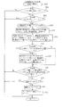
次に、上記のように構成されたパチンコ機Pで実行される各処理を、図6から図11の各フローチャートを参照して説明する。図6は、パチンコ機Pの主制御基板Cにおいて実行されるメイン処理のフローチャートである。メイン処理では、バックアップデータがある場合の復元や、RAMやI/O等の各値の初期化、及び、タイマ割込等の各割込の設定を行う等の初期化処理(S11)を実行し、その後に、S12からS18の各処理を所定時間毎(例えば、2ms毎)に繰り返し実行して、遊技の制御を行う。   Next, each process executed by the pachinko machine P configured as described above will be described with reference to the flowcharts of FIGS. FIG. 6 is a flowchart of a main process executed on the main control board C of the pachinko machine P. In the main processing, initialization processing (S11) such as restoration when there is backup data, initialization of each value such as RAM and I / O, and setting of each interrupt such as a timer interrupt is executed. Then, each process from S12 to S18 is repeatedly executed at predetermined time intervals (for example, every 2 ms) to control the game.

始動入賞処理(S12)では、球が図柄作動口(始動口)4へ入賞したか否かを確認して変動表示の内容を設定する。変動開始処理(S13)では、変動開始のタイミングであれば、変動表示を開始させる表示コマンドを表示用制御基板Dへ送信する。この始動入賞処理(S12)及び変動開始処理(S13)の詳細については図7から図10を参照して後述する。   In the start winning process (S12), it is confirmed whether or not the ball has won the symbol operating port (starting port) 4 and the contents of the variable display are set. In the variation start process (S13), a display command for starting variation display is transmitted to the display control board D at the variation start timing. Details of the start winning process (S12) and the change start process (S13) will be described later with reference to FIGS.

変動停止処理(S14)では、まず、大当たり中であるか否かを判定する。ここで、大当たり中には、大当たりの際にLCD3で表示される特別遊技の最中と特別遊技終了後の所定時間の最中とが含まれる。特別遊技終了後の所定時間は、例えばパチンコ機Pの各状態を整えるのに要する時間などとして設定される。大当たり中ではないと判定されると、リーチ表示の有無など変動表示の内容に応じて区分けした種別を表す変動パターンにおける変動時間が終了しているか否かを判定する。この処理は、各変動パターン毎に設定された変動時間が経過したかを判定することにより行われる。変動時間が終了していれば、変動の停止と確認のために制御用コマンドの1つである確定コマンドを表示用制御基板Dへ出力し、この処理を終了する。表示用制御基板Dは、確定コマンドを入力すると、LCD3の変動表示を停止表示(確定)させる。   In the fluctuation stop process (S14), it is first determined whether or not a big hit is being made. Here, the jackpot includes a special game displayed on the LCD 3 at the time of the big jackpot and a predetermined time after the special game ends. The predetermined time after the end of the special game is set as, for example, the time required for adjusting each state of the pachinko machine P. If it is determined that it is not a big hit, it is determined whether or not the variation time in the variation pattern representing the type classified according to the content of the variation display such as the presence or absence of reach display has ended. This process is performed by determining whether or not the variation time set for each variation pattern has elapsed. If the fluctuation time has ended, a confirmation command, which is one of the control commands, is output to the display control board D for stopping and checking the fluctuation, and this process is ended. When the confirmation control board D inputs the confirmation command, the display control board D stops and displays (determines) the fluctuation display on the LCD 3.

カウンタ更新処理(S15)では、内部乱数カウンタ23b、リーチ乱数カウンタ23c、連継演出乱数カウンタ23d、及び、大当たり図柄カウンタ23eの各カウンタの値を更新する。大当たり処理(S16)では、大当たりか否かを判定し、大当たりである場合には特定入賞口5(図1参照)の開放処理を行う。一方、大当たりでない場合には、該処理をスキップしてこの処理を終了する。特定入賞口5の開放処理では、球が入賞しやすいように特定入賞口5を所定時間(例えば、30秒経過するまで、或いは、球が10個入賞するまで)開放する。特定入賞口5の開放中に、球がVゾーン5aを通過すると、継続権を成立させて、特定入賞口5の閉鎖後、再度、その特定入賞口5を所定時間(又は、球が10個入賞するまで)開放する。この特定入賞口5の開閉動作を、最高で16回(16ラウンド)繰り返す。   In the counter update process (S15), the values of the internal random number counter 23b, the reach random number counter 23c, the continuous effect random number counter 23d, and the jackpot symbol counter 23e are updated. In the jackpot process (S16), it is determined whether or not the jackpot is big. If the jackpot is big, the specific winning opening 5 (see FIG. 1) is released. On the other hand, if it is not a big hit, the process is skipped and the process is terminated. In the opening process of the specific winning opening 5, the specific winning opening 5 is opened for a predetermined time (for example, until 30 seconds have passed or 10 balls have been won) so that the balls can easily win. If the ball passes through the V zone 5a while the specific winning opening 5 is opened, the continuation right is established, and after the specific winning opening 5 is closed, the specific winning opening 5 is held again for a predetermined time (or 10 balls). Open until you win. The opening / closing operation of the specific winning award 5 is repeated up to 16 times (16 rounds).

ハズレ図柄カウンタ更新処理(S17)では、ハズレ図柄カウンタ23fの値を更新する。その後、次のS12の処理の実行タイミングが到来するまでの残余時間の間、ハズレ図柄カウンタ更新処理(S17)を繰り返し実行する。S12〜S16の各処理は定期的に実行する必要があるので、S18の処理において、前回のS12の処理の実行からの経過時間をチェックする(S18)。チェックの結果、前回のS12の処理の実行から所定時間(例えば2ms)経過していれば(S18:Yes)、処理をS12へ移行する。一方、所定時間経過していなければ(S18:No)、処理をS17へ移行して、ハズレ図柄カウンタ更新処理(S17)を繰り返す。ここで、S12〜S16の各処理の実行時間は、遊技の状態に応じて変化するので、次のS12の処理の実行タイミングが到来するまでの残余時間は、一定の時間ではない。よって、かかる残余時間を使用してハズレ図柄カウンタ更新処理(S17)を繰り返し実行することにより、ハズレ図柄カウンタ23fの値をランダムに更新することができる。   In the lost symbol counter update process (S17), the value of the lost symbol counter 23f is updated. After that, the lost symbol counter update process (S17) is repeatedly executed for the remaining time until the next execution timing of the process of S12 comes. Since each process of S12 to S16 needs to be executed periodically, in the process of S18, an elapsed time from the previous execution of the process of S12 is checked (S18). As a result of the check, if a predetermined time (for example, 2 ms) has elapsed since the previous execution of the process of S12 (S18: Yes), the process proceeds to S12. On the other hand, if the predetermined time has not elapsed (S18: No), the process proceeds to S17, and the lost symbol counter update process (S17) is repeated. Here, since the execution time of each process of S12-S16 changes according to the state of a game, the remaining time until the next execution timing of the process of S12 comes is not a fixed time. Therefore, by repeatedly executing the lost symbol counter update process (S17) using the remaining time, the value of the lost symbol counter 23f can be updated at random.

図7は、主制御基板Cのメイン処理(図6参照)の中で実行される始動入賞処理(S12)のフローチャートである。この始動入賞処理(S12)は、始動入賞の有無を確認し、始動入賞があった場合には、そのタイミングで変動表示の内容としての変動パターンや停止図柄等の態様を選定する処理である。   FIG. 7 is a flowchart of the start winning process (S12) executed in the main process (see FIG. 6) of the main control board C. This start winning process (S12) is a process of confirming whether or not there is a start winning, and when there is a starting winning, selecting a variation pattern, a stop pattern, etc. as the contents of the variable display at that timing.

この始動入賞処理(S12)では、まず、始動口スイッチ27が球を検出したか否かを確認する(S21)。球を検出していれば(S21:Yes)、保留球カウンタ23aの値が「4」以上であるか否かを確認する(S22)。その値が「4」未満であれば(S22:No)、変動表示のデータが最大の待機回数分記憶されていないので、保留球カウンタ23aの値に「1」を加算した後(S23)、加算後の保留球カウンタ23aの値を付加した始動入賞コマンドを表示用制御基板Dへ送信する(S24)。   In the start winning process (S12), first, it is confirmed whether or not the start port switch 27 has detected a ball (S21). If a sphere is detected (S21: Yes), it is confirmed whether or not the value of the retained sphere counter 23a is equal to or greater than “4” (S22). If the value is less than “4” (S22: No), since the variable display data is not stored for the maximum number of standby times, “1” is added to the value of the reserved ball counter 23a (S23). A start winning command to which the value of the retained ball counter 23a after the addition is added is transmitted to the display control board D (S24).

始動入賞コマンドは、2バイトのデータで構成され、始動入賞の発生を示す1バイト目のデータと、「1」から「4」の保留球カウンタ23aの値を示す2バイト目のデータとにより構成される。主制御基板Cからの制御用コマンドの送信は、図示しない主制御基板CのRAM23に設けられる送信バッファにコマンドが一旦書き込まれ、その書き込み順に表示用制御基板Dへ1バイトずつ送信される。   The start winning command is composed of 2-byte data, and is composed of the first byte data indicating the occurrence of the starting win and the second byte data indicating the value of the holding ball counter 23a from “1” to “4”. Is done. For transmission of a control command from the main control board C, the command is once written in a transmission buffer provided in the RAM 23 of the main control board C (not shown), and is transmitted byte by byte to the display control board D in the order of writing.

S24の処理後、内部乱数カウンタ23b、リーチ乱数カウンタ23c、連継演出乱数カウンタ23d、大当たり図柄カウンタ23e、及び、ハズレ図柄カウンタ23fの各値を変動表示のデータとして保留球カウンタ23aの値が示す演出実行1〜4メモリ23h〜23kに書き込んで記憶し(S25)、内部乱数カウンタ23bの値が大当たりを発生させる値の1つである「7」であるか否かを確認する(S26)。   After the processing of S24, the value of the holding ball counter 23a indicates each value of the internal random number counter 23b, the reach random number counter 23c, the continuous effect random number counter 23d, the jackpot symbol counter 23e, and the lost symbol counter 23f as data of fluctuation display. The performance execution 1 to 4 memories 23h to 23k are written and stored (S25), and it is confirmed whether or not the value of the internal random number counter 23b is "7", which is one of the values for generating a big hit (S26).

S26の処理において内部乱数カウンタ23bの値が大当たりを発生させる値「7」であれば(S26:Yes)、連継演出の実行条件の成立となり、保留球カウンタ23aの値が示す演出実行1〜4メモリ23h〜23kに記憶された連継演出乱数カウンタ23dの値を、連継演出の実行に対応する値「7」に書き換えて(S27)、処理をS28へ移行する。一方、S26の処理において内部乱数カウンタ23bの値が「7」以外の値であれば(S26:No)、S27の処理をスキップして処理をS28へ移行する。   If the value of the internal random number counter 23b in the process of S26 is a value “7” that generates a big hit (S26: Yes), the execution condition of the continuous effect is established, and the performance execution 1 to 1 indicated by the value of the reserved ball counter 23a is established. The value of the continuous effect random number counter 23d stored in the four memories 23h to 23k is rewritten to a value “7” corresponding to the execution of the continuous effect (S27), and the process proceeds to S28. On the other hand, if the value of the internal random number counter 23b is a value other than “7” in the process of S26 (S26: No), the process of S27 is skipped and the process proceeds to S28.

ここで、内部乱数カウンタ23bの値が大当たりを発生させる値としては、「7」と「315」との2種類があり、このうち「7」である場合に限ってS27の処理において変動表示のデータを書き換えて、大当たりを発生させる変動表示とその時点で待機中の変動表示とによる連継演出を実行させる。よって、大当たりが発生する場合に必ずしも連継演出が実行されるとは限らないので、遊技者には、連継演出を構成する変動表示以外の変動表示に対しても大当たりの発生を期待させることができる。   Here, there are two kinds of values “7” and “315” that cause the value of the internal random number counter 23b to generate a big hit. The data is rewritten, and a continuous effect is executed by the change display that generates a big hit and the change display that is waiting at that time. Therefore, since a continuous effect is not always executed when a big hit occurs, the player is expected to expect a big win even for a variable display other than the variable display constituting the continuous effect. Can do.

S28の処理では、保留球カウンタ23aの値が示す演出実行1〜4メモリ23h〜23kに記憶された連継演出乱数カウンタ23dの値が「7」か確認する(S28)。連継演出乱数カウンタ23dの値が「7」であれば(S28:Yes)、連継フラグ23mがオンであるか確認する(S29)。連継フラグ23mがオンでなければ(S29:No)、連継演出の実行条件の成立となり、連継フラグをオンし(S30)、ラウンド数カウンタ23nの値を「0」クリアして(S31)、この始動入賞処理(S12)を終了する。S29の処理において連継フラグ23mがオンであれば(S29:Yes)、S30及びS31の処理をスキップして始動入賞処理(S12)を終了する。S29の処理で連継フラグ23mがオフである場合に限ってラウンド数カウンタ23nの値が「0」クリアするので、連継演出の実行期間中に再度連継演出の実行条件が成立してもラウンド数カウンタ23nの値が「0」クリアされず、ラウンド数カウンタ23nの値を正しく更新できる。   In the process of S28, it is confirmed whether the value of the continuous effect random number counter 23d stored in the effect execution 1-4 memories 23h-23k indicated by the value of the reserved ball counter 23a is “7” (S28). If the value of the continuous effect random number counter 23d is “7” (S28: Yes), it is confirmed whether the continuous flag 23m is on (S29). If the continuous flag 23m is not on (S29: No), the execution condition of the continuous effect is established, the continuous flag is turned on (S30), and the value of the round number counter 23n is cleared to “0” (S31). ), The start winning process (S12) is terminated. If the continuous flag 23m is on in the process of S29 (S29: Yes), the process of S30 and S31 is skipped and the start winning process (S12) is ended. Since the value of the round number counter 23n is cleared to “0” only when the continuous flag 23m is off in the process of S29, even if the execution condition of the continuous effect is satisfied again during the continuous effect execution period. The value of the round number counter 23n is not cleared to “0”, and the value of the round number counter 23n can be correctly updated.

S28の処理で、保留球カウンタ23aの値が示す演出実行1〜4メモリ23h〜23kに記憶された連継演出乱数カウンタ23dの値が「7」でなければ(S28:No)、連継演出の実行条件が成立していないので、S29〜S31の処理をスキップして始動入賞処理(S12)を終了する。また、S21の処理において、始動口スイッチ27が球を検出していなければ(S21:No)、始動入賞の成立時でなく、また、S22の処理において保留球カウンタ23aの値が「4」以上であれば(S22:Yes)、最大待機回数分の変動表示のデータが記憶されているので、S23〜S27の処理をスキップして始動入賞処理(S12)を終了する。   In the process of S28, if the value of the continuous effect random number counter 23d stored in the effect execution 1-4 memory 23h-23k indicated by the value of the reserved ball counter 23a is not "7" (S28: No), the continuous effect Since the execution condition is not established, the processes of S29 to S31 are skipped and the start winning process (S12) is terminated. If the start switch 27 does not detect a ball in the process of S21 (S21: No), it is not when the start winning is established, and the value of the holding ball counter 23a is “4” or more in the process of S22. If so (S22: Yes), since the variable display data for the maximum number of standby times is stored, the processing of S23 to S27 is skipped and the start winning process (S12) is terminated.

図8は、主制御基板Cのメイン処理(図6参照)の中で実行される変動開始処理(S13)のフローチャートである。この変動開始処理(S13)は、始動入賞処理(S12)で選定された態様に従って表示用制御基板Dに送信する表示コマンドを決定して、始動入賞のタイミングで選定された態様による変動表示を表示用制御基板Dを介してLCD3に行わせる処理である。   FIG. 8 is a flowchart of the change start process (S13) executed in the main process (see FIG. 6) of the main control board C. In the variation start process (S13), a display command to be transmitted to the display control board D is determined according to the mode selected in the start winning process (S12), and the variation display according to the mode selected at the start winning timing is displayed. This process is performed by the LCD 3 via the control board D.

変動開始処理(S13)では、まず、保留球カウンタ23aの値が「1」以上であるか否かを確認する(S41)。「1」以上であれば(S41:Yes)、変動表示中か又は大当たり中(所定の遊技価値が付与される特別遊技状態中)であるか否かを確認する(S42)。変動表示中でなく且つ大当たり中でもなければ(S42:No)、保留球カウンタ23aの値から「1」を減算して(S43)、演出実行1メモリ23hに記憶されて演出を実行するための変動表示のデータを演出実行エリア23gに書き込む(S44)。更に、演出実行2〜4メモリ23i〜23kに演出実行用のデータとして記憶されている変動表示のデータを、演出実行1〜3メモリ23h〜23jへそれぞれ1つずつシフトする(S45)。   In the variation start process (S13), first, it is confirmed whether or not the value of the reserved ball counter 23a is equal to or greater than “1” (S41). If it is “1” or more (S41: Yes), it is confirmed whether or not it is in a variable display or a jackpot (in a special game state to which a predetermined game value is given) (S42). If the fluctuation display is not being performed and the big hit is not being made (S42: No), “1” is subtracted from the value of the holding ball counter 23a (S43), and the fluctuation for executing the presentation stored in the presentation execution 1 memory 23h. The display data is written in the effect execution area 23g (S44). Further, the variation display data stored in the execution execution 2 to 4 memories 23i to 23k as the data for execution execution are shifted one by one to the execution execution 1 to 3 memories 23h to 23j (S45).

次に、連継フラグ23mがオンか確認し(S46)、オンでなければ(S46:No)、通常の変動表示の内容を選定するための通常変動選定処理を実行して表示用制御基板Dへ送信する表示コマンドを決定し(S47)、決定された表示コマンドを表示用制御基板Dへ送信して(S49)変動開始処理を終了する。S46の処理において連継フラグ23mがオンであれば(S46:Yes)、連継演出を構成する専用の変動表示の内容を選定するための連継演出選定処理を実行して表示コマンドを決定し(S48)、処理をS49へ移行する。連継フラグ23mのオンオフに応じて別々の処理により変動表示を設定するので、連継フラグ23mがオンとなって連継演出の実行条件が成立している間には、専用の変動表示を選定することができる。   Next, it is confirmed whether or not the connection flag 23m is on (S46). If it is not on (S46: No), a normal variation selection process for selecting the contents of the normal variation display is executed to display the control board D for display. The display command to be transmitted is determined (S47), the determined display command is transmitted to the display control board D (S49), and the variation start process is terminated. If the continuous flag 23m is on in the process of S46 (S46: Yes), the display command is determined by executing the continuous effect selection process for selecting the contents of the dedicated variable display constituting the continuous effect. (S48), the process proceeds to S49. Since the variable display is set by a separate process depending on whether the continuous flag 23m is on or off, the dedicated variable display is selected while the continuous flag 23m is on and the execution condition of the continuous effect is established. can do.

一方、S41の処理において保留球カウンタ23aの値が「1」未満、即ち、「0」であることが確認された場合(S41:No)、及び、S42の処理において変動表示中か又は大当たり中であることが確認された場合には(S42:Yes)、S43〜S49の各処理をスキップして変動開始処理(S13)を終了する。   On the other hand, when it is confirmed in the process of S41 that the value of the holding ball counter 23a is less than “1”, that is, “0” (S41: No), and in the process of S42, the variable display or the big hit Is confirmed (S42: Yes), each process of S43 to S49 is skipped and the variation start process (S13) is terminated.

図9は、図8に示す変動開始処理(S13)の中で実行される通常変動選定処理(S47)のフローチャートである。通常変動選定処理(S47)では、連継演出を構成する専用の変動表示以外の通常の変動表示に対する変動パターンを選定する処理であり、始動入賞時に取得された変動表示のデータに基づいて変動表示の内容を選定し、表示用制御基板Dへ送信する表示コマンドを決定する。   FIG. 9 is a flowchart of the normal variation selection process (S47) executed in the variation start process (S13) shown in FIG. The normal variation selection process (S47) is a process for selecting a variation pattern for a normal variation display other than the dedicated variation display constituting the continuous effect, and the variation display based on the variation display data acquired at the time of winning the start. Is selected and a display command to be transmitted to the display control board D is determined.

この通常変動選定処理(S47)では、まず、演出実行エリア23gに記憶された内部乱数カウンタ23bの値が大当たりを発生させる値か確認し(S51)、その値が大当たりを発生させる値であれば(S51:Yes)、演出実行エリア23gに記憶された大当たり図柄カウンタ23eの値に対応した図柄の組み合わせを示す値を停止図柄コマンドに設定する(S52)。その後、リーチ表示を伴う変動パターン(リーチパターン)に対応した値を、大当たりを発生させる複数の変動パターン毎に別々の変動パターンコマンドを対応させた大当たりテーブルより抽出して変動パターンコマンドに設定する(S53)。変動パターンコマンドと停止図柄コマンドとの設定は、RAM23に割り当てられた送信バッファに各コマンドを示す値が書き込まれることにより行われる。S53の処理の後には、この通常変動選定処理(S47)を終了し、図8に示す変動開始処理(S13)に処理を戻す。   In this normal variation selection process (S47), first, it is confirmed whether or not the value of the internal random number counter 23b stored in the effect execution area 23g is a value that generates a jackpot (S51), and if the value is a value that generates a jackpot. (S51: Yes), a value indicating a combination of symbols corresponding to the value of the jackpot symbol counter 23e stored in the effect execution area 23g is set in the stop symbol command (S52). Thereafter, a value corresponding to a variation pattern with reach display (reach pattern) is extracted from a jackpot table in which different variation pattern commands are associated with each of a plurality of variation patterns that generate a jackpot, and set as a variation pattern command ( S53). The setting of the variation pattern command and the stop symbol command is performed by writing a value indicating each command in the transmission buffer assigned to the RAM 23. After the process of S53, this normal fluctuation selection process (S47) is terminated, and the process returns to the fluctuation start process (S13) shown in FIG.

S51の処理において内部乱数カウンタ23bの値が大当たりを発生させる値でない場合には(S51:No)、演出実行エリア23gに記憶されたリーチ乱数カウンタ23cの値がハズレリーチを発生させる値であるか否かを確認する(S54)。その値がハズレリーチを発生させる値であれば(S54:Yes)、カウンタ用バッファ23lに記憶されたハズレリーチを構成する変動図柄Zの組み合わせを示す値を停止図柄コマンドに設定する(S55)。その後、リーチパターンに対応した値を、ハズレリーチを発生させる複数の変動パターン毎に別々の変動パターンコマンドを対応させたハズレリーチテーブルより抽出して変動パターンコマンドに設定し(S56)、この通常変動選定処理(S47)を終了する。   In the process of S51, if the value of the internal random number counter 23b is not a value that generates a big hit (S51: No), whether the value of the reach random number counter 23c stored in the effect execution area 23g is a value that generates a lost reach. It is confirmed whether or not (S54). If the value is a value that causes a loss reach (S54: Yes), a value indicating a combination of the variable symbols Z constituting the loss reach stored in the counter buffer 23l is set in the stop symbol command (S55). Thereafter, a value corresponding to the reach pattern is extracted from a haze reach table in which a different variation pattern command is associated with each of a plurality of variation patterns that generate a loss reach, and set as a variation pattern command (S56). The selection process (S47) ends.

S54の処理において演出実行エリア23gに記憶されたリーチ乱数カウンタ23cの値がハズレリーチを発生させる値でない場合には(S54:No)、演出実行エリア23gに記憶されたハズレ図柄カウンタ23fの値を停止図柄コマンドに設定する(S57)。その後、リーチ表示伴わないハズレの変動パターン(ハズレパターン)に対応した値を変動パターンコマンドに設定して(S58)、この通常変動選定処理(S47)を終了する。   When the value of the reach random number counter 23c stored in the effect execution area 23g in the process of S54 is not a value that causes the lose reach (S54: No), the value of the lose symbol counter 23f stored in the effect execution area 23g is set. The stop symbol command is set (S57). After that, a value corresponding to the variation pattern of loss (loss pattern) not accompanied by reach display is set in the variation pattern command (S58), and this normal variation selection process (S47) is terminated.

図10は、図8に示す変動開始処理(S13)の中で実行される連継演出選定処理(S48)のフローチャートである。連継演出選定処理(S48)は、連継演出を構成する変動表示の変動パターンの中から変動パターンを選定する処理であり、始動入賞時に取得された変動表示のデータに基づいて変動表示の内容を選定し、表示用制御基板Dへ送信する表示コマンドを決定する。   FIG. 10 is a flowchart of the continuous effect selection process (S48) executed in the variation start process (S13) shown in FIG. The continuous effect selection process (S48) is a process for selecting a variation pattern from the variation patterns of the variation display that constitutes the continuous effect, and the contents of the variation display based on the variation display data acquired at the time of starting winning a prize. And a display command to be transmitted to the display control board D is determined.

この連継演出選定処理(S48)では、まず、ラウンド数カウンタ23nの値に「1」を加算し(S61)、加算後のラウンド数カウンタ23nの値に対応した値を変動パターンコマンドの上位バイトに設定する。例えば、ラウンド数カウンタ23nの値が「1」であれば「C1h」、ラウンド数カウンタ23nの値が「3」であれば「C3h」の値を変動パターンコマンドの上位バイトとする。なお、連継演出を構成する変動表示以外の通常の変動表示に対しては「C0h」を変動パターンコマンドの上位バイトとする。表示用制御基板Dは、変動パターンコマンドの上位バイトを確認して、連継演出を構成する変動表示であるか否かを判別して適当な変動表示を選定し、更にラウンド数カウンタ23nの値に対応したラウンド数Rの画像を連継演出中にLCD3の表示画面3aに表示する。   In this continuous effect selection process (S48), first, “1” is added to the value of the round number counter 23n (S61), and the value corresponding to the value of the round number counter 23n after the addition is set to the upper byte of the variation pattern command. Set to. For example, if the value of the round number counter 23n is “1”, “C1h” is used, and if the value of the round number counter 23n is “3”, the value “C3h” is used as the upper byte of the variation pattern command. Note that “C0h” is used as the upper byte of the fluctuation pattern command for normal fluctuation display other than the fluctuation display constituting the continuous effect. The display control board D confirms the upper byte of the variation pattern command, determines whether or not the variation display constitutes the continuous effect, selects an appropriate variation display, and further selects the value of the round number counter 23n. The image of the round number R corresponding to is displayed on the display screen 3a of the LCD 3 during the continuous effect.

S62の処理の後、演出実行エリア23gに記憶された内部乱数カウンタ23bの値が大当たりを発生させる値か確認し(S63)、その値が大当たりを発生させる値でなければ(S63:No)、演出実行エリア23gに記憶されたハズレ図柄カウンタ23fの値を停止図柄コマンドに設定する(S64)。次に演出実行エリア23gに記憶された連継演出乱数カウンタ23dの値が「7」か確認し、その値が「7」でなければ(S65:No)、継続パターンに対応した値「01h」を変動パターンコマンドの下位バイトに設定して(S66)、この連継演出選定処理(S48)を終了する。この継続パターンが選定される場合には、連継フラグをオフする処理(S68)がスキップされるので、次回に開始される変動表示を再度連継演出を構成する変動表示とすることができる。   After the process of S62, it is confirmed whether the value of the internal random number counter 23b stored in the effect execution area 23g is a value that generates a big jackpot (S63). The value of the lost symbol counter 23f stored in the effect execution area 23g is set as a stop symbol command (S64). Next, it is checked whether the value of the continuous effect random number counter 23d stored in the effect execution area 23g is “7”. If the value is not “7” (S65: No), the value “01h” corresponding to the continuation pattern is obtained. Is set in the lower byte of the variation pattern command (S66), and the continuous effect selection process (S48) is terminated. When this continuation pattern is selected, the process of turning off the continuous flag (S68) is skipped, so that the next variable display that is started can be changed to the variable display that constitutes the continuous effect.

S65の処理で演出実行エリア23gに記憶された連継演出乱数カウンタ23gの値が「7」であれば(S65:Yes)、敗北パターンに対応した値「02h」を変動パターンコマンドの下位バイトに設定し(S67)、連継フラグ23mをオフして(S68)、この連継演出選定処理(S48)を終了する。S68の処理で連継フラグ23mがオフされるので、敗北パターンの後に開始される変動表示は、通常の変動表示とすることができる。   If the value of the continuous effect random number counter 23g stored in the effect execution area 23g in the process of S65 is “7” (S65: Yes), the value “02h” corresponding to the defeat pattern is used as the lower byte of the variation pattern command. The setting is made (S67), the continuous flag 23m is turned off (S68), and the continuous effect selection process (S48) is ended. Since the succession flag 23m is turned off in the process of S68, the fluctuation display started after the defeat pattern can be a normal fluctuation display.

S63の処理で演出実行エリア23gに記憶された内部乱数カウンタ23bの値が大当たりを発生させる値であることが確認されると(S63:Yes)、演出実行エリア23gに記憶された大当たり図柄カウンタ23eの値に対応した変動図柄10の組み合わせを示す値を停止図柄コマンドに設定する(S69)。その後、勝利パターンに対応した値「03h」を変動パターンコマンドの下位バイトに設定し(S70)、連継フラグ23mをオフして(S68)、この連継演出選定処理(S48)を終了する。   When it is confirmed in the process of S63 that the value of the internal random number counter 23b stored in the effect execution area 23g is a value that generates a jackpot (S63: Yes), the jackpot symbol counter 23e stored in the effect execution area 23g. A value indicating the combination of the variation symbols 10 corresponding to the value of is set in the stop symbol command (S69). Thereafter, the value “03h” corresponding to the winning pattern is set in the lower byte of the variation pattern command (S70), the continuous flag 23m is turned off (S68), and this continuous effect selection process (S48) is terminated.

ここで、S63の処理によって演出実行エリア23gに記憶された内部乱数カウンタ23bの値が大当たりを発生させる値であると確認されると、S65の処理で確認される連継演出乱数カウンタ23dの値に関係なく、勝利パターンに対応した変動パターン(変動パターンコマンド)が選定される。これにより、連継演出の実行条件が成立した変動表示の前に偶然に大当たりを発生させる変動表示が待機されていた場合であっても敗北パターンや継続パターンによる変動表示の表示結果が大当たりとなって不自然な変動表示となることを防止している。   Here, if it is confirmed that the value of the internal random number counter 23b stored in the effect execution area 23g by the process of S63 is a value that generates a big hit, the value of the continuous effect random number counter 23d confirmed in the process of S65 Regardless of the variation pattern, the variation pattern (variation pattern command) corresponding to the winning pattern is selected. As a result, even if the variable display that accidentally generates a jackpot is waited before the variable display for which the execution condition of the continuous effect is established, the display result of the variable display by the defeat pattern or the continuation pattern becomes a big hit. To prevent unnatural fluctuation display.

図11は、表示用制御基板Dで実行されるコマンド受信処理のフローチャートである。このコマンド受信処理は、表示用制御基板Dにおいて主制御基板Cからコマンドを受信した場合に実行される割込処理であり、この処理によって主制御基板Cから送信されたコマンドに予め対応付けされた処理が表示用制御基板Dで行われる。   FIG. 11 is a flowchart of command reception processing executed by the display control board D. This command reception process is an interrupt process executed when a command is received from the main control board C in the display control board D, and is associated in advance with the command transmitted from the main control board C by this process. Processing is performed on the display control board D.

このコマンド受信処理では、まず、始動入賞コマンドを受信したか確認する(S71)。始動入賞コマンドを受信していれば(S71:Yes)、図柄作動口4へ球が入賞したタイミングであるので、保留球カウンタ33aの値を「1」加算する(S72)。更に、保留球カウンタ33aの値を付加した点灯コマンドを音声ランプ制御基板Lへ送信し(S73)、音声ランプ制御基板Lの制御により回数表示部8a〜8dの点灯状態を更新させる。S71の処理において始動入賞コマンドを受信していなければ(S71:No)、始動入賞コマンド以外のコマンドを受信しているので、S72およびS73の処理をスキップして処理をS74へ移行する。   In this command reception process, first, it is confirmed whether a start winning command has been received (S71). If the start winning command has been received (S71: Yes), it is the timing when the ball has won the symbol operating port 4, and therefore the value of the holding ball counter 33a is incremented by "1" (S72). Further, a lighting command to which the value of the holding ball counter 33a is added is transmitted to the sound lamp control board L (S73), and the lighting states of the number display sections 8a to 8d are updated under the control of the sound lamp control board L. If the start winning command has not been received in the processing of S71 (S71: No), the command other than the starting winning command has been received, so the processing of S72 and S73 is skipped and the processing proceeds to S74.

S74の処理では、表示コマンドを受信したか確認する(S74)。表示コマンドの受信でなければ(S74:No)、表示コマンドの受信時に実行する各処理をスキップして処理をS83へ移行する。表示コマンドの受信が確認されると(S74:Yes)、表示コマンドを構成する変動パターンコマンドと停止図柄コマンドとを演出実行エリア33cに書き込む(S75)。また、表示コマンドを受信した場合には変動表示を開始するタイミングであるので、保留球カウンタ33aの値を「1」減算すると共に(S76)、減算した保留球カウンタ33aの値を付加した点灯コマンドを音声ランプ制御基板Lへ送信し(S77)、音声ランプ制御基板Lに回数表示部8a〜8dの点灯状態を更新させる。   In the process of S74, it is confirmed whether a display command has been received (S74). If the display command is not received (S74: No), each process executed when the display command is received is skipped, and the process proceeds to S83. When reception of the display command is confirmed (S74: Yes), the variation pattern command and the stop symbol command constituting the display command are written in the effect execution area 33c (S75). When the display command is received, it is the timing to start the variable display, so that the value of the holding ball counter 33a is decremented by “1” (S76), and the lighting command to which the value of the subtracted holding ball counter 33a is added. Is transmitted to the sound lamp control board L (S77), and the sound lamp control board L is caused to update the lighting states of the number of times display portions 8a to 8d.

S77の処理後、受信した表示コマンドが「ラウンド1」を示すものか確認する(S78)。「ラウンド1」を示す表示コマンドとは、変動パターンコマンドの上位バイトが「C1h」であって連継演出の実行条件が成立した後の最初の変動表示を示すものである。受信した表示コマンドが「ラウンド1」を示すものであれば(S78:Yes)、遮蔽用ソレノイド12をオンし(S79)、処理をS80へ移行する。遮蔽用ソレノイド12がオンされると、シャッター11が閉鎖位置に配置されて回数表示部8a〜8dが覆い隠される。このため、連継演出の実行条件成立後の最初の変動表示が開始されるタイミングで回数表示部8a〜8dを覆い隠すことができ、始動入賞時に大当たりを発生させると判定されたときに待機されていた全ての変動表示が実行される期間にわたって回数表示部8a〜8dを覆い隠した状態を継続できる。   After the processing of S77, it is confirmed whether or not the received display command indicates “round 1” (S78). The display command indicating “Round 1” indicates the first change display after the upper byte of the change pattern command is “C1h” and the execution condition of the continuous effect is established. If the received display command indicates “round 1” (S78: Yes), the shielding solenoid 12 is turned on (S79), and the process proceeds to S80. When the shielding solenoid 12 is turned on, the shutter 11 is disposed at the closed position and the number of times display portions 8a to 8d are covered. For this reason, the number of display portions 8a to 8d can be obscured at the timing when the first variation display after the execution condition of the continuous effect is established, and the system waits when it is determined that a big hit will be generated at the time of start winning. The state where the number display sections 8a to 8d are obscured can be continued over a period in which all the variable displays are executed.

ここで、回数表示部8a〜8dを覆い隠すタイミングは、連継演出の実行条件が成立したタイミングとしても良い。図7の始動入賞処理で連継フラグをオンするタイミングで遮蔽用ソレノイド12をオンさせるコマンドを主制御基板Cから送信し、そのコマンドを受信したタイミングで表示用制御基板Dは、遮蔽用ソレノイド12をオンするようにしても良い。回数表示部8a〜8dを覆い隠した状態をより長く継続することができる。   Here, the timing at which the number display sections 8a to 8d are covered may be the timing at which the execution condition of the continuous effect is established. A command for turning on the shielding solenoid 12 is transmitted from the main control board C at the timing when the continuous flag is turned on in the start winning process of FIG. 7, and the display control board D receives the command at the timing when the command is received. You may make it turn on. It is possible to continue the state of covering the number display sections 8a to 8d for a longer time.

S78の処理において受信した表示コマンドが「ラウンド1」を示すものでなければ(S78:No)、遮蔽用ソレノイド12をオンすることなく処理をS80へ移行する。S80の処理では、受信した表示コマンドが勝利パターン又は敗北パターンを示すものか確認し(S80)、それらのパターンであれば(S80:Yes)、連継終了フラグ33bをオンして変動終了時に遮蔽用ソレノイド12をオフさせることを記憶し(S81)、変動表示を開始させる(S82)。S80の処理で、受信した表示コマンドが勝利パターン及び敗北パターンでないことが確認されると(S80:No)、連継終了フラグ33bをオンしないで変動表示を開始させる(S82)。S82の処理で主制御基板Cが選定した変動パターンおよび停止図柄に基づいて変動表示が開始されると、各変動パターンの変動時間が経過するまで図示しない処理によってLCD3の表示制御、ランプ28の点灯制御、スピーカ29の音声出力制御等が行われるが、一般的な処理であるのでその説明を省略する。   If the display command received in the process of S78 does not indicate “Round 1” (S78: No), the process proceeds to S80 without turning on the shielding solenoid 12. In the process of S80, it is confirmed whether or not the received display command indicates a victory pattern or a defeat pattern (S80). The fact that the solenoid 12 is turned off is memorized (S81), and the fluctuation display is started (S82). If it is confirmed in the process of S80 that the received display command is not a victory pattern or a defeat pattern (S80: No), the variable display is started without turning on the continuation end flag 33b (S82). When the variation display is started based on the variation pattern and stop pattern selected by the main control board C in the process of S82, the display control of the LCD 3 and the lighting of the lamp 28 are performed by the processing not shown until the variation time of each variation pattern elapses. Control, audio output control of the speaker 29, and the like are performed, but since it is a general process, its description is omitted.

S83の処理では、確定コマンドを受信したか確認する(S83)。確定コマンドの受信が確認されると(S83:Yes)、変動表示を停止表示させて確定させ(S84)、連継終了フラグ33bがオンか確認する(S85)。連継終了フラグ33bがオンであれば(S85:Yes)、連継演出を終了させるタイミングであるので、遮蔽用ソレノイド12をオフしてシャッター11を上昇させ、回数表示部8a〜8dの前面を開放する。その後、連継終了フラグ33bをオフして(S87)、処理をS88へ移行する。   In the process of S83, it is confirmed whether a confirmation command has been received (S83). When reception of the confirmation command is confirmed (S83: Yes), the variable display is stopped and confirmed (S84), and it is confirmed whether the connection end flag 33b is on (S85). If the continuous end flag 33b is on (S85: Yes), it is the timing to end the continuous effect, so the shielding solenoid 12 is turned off to raise the shutter 11, and the front of the number display sections 8a to 8d is displayed. Open. Thereafter, the continuous end flag 33b is turned off (S87), and the process proceeds to S88.

S83の処理において確定コマンドの受信でない場合(S83:No)、及び、S85の処理において連継終了フラグ33bがオフである場合には(S85:No)、S86及びS87の処理をスキップして処理をS88へ移行する。S88の処理では、上記したコマンド以外の他のコマンドの受信時に受信したコマンドに対応するその他処理が行われ(S88)、コマンド受信処理は終了する。   If the confirmation command is not received in the process of S83 (S83: No), and if the continuous end flag 33b is OFF in the process of S85 (S85: No), the process of S86 and S87 is skipped. To S88. In the processing of S88, other processing corresponding to the command received when receiving the command other than the above-described command is performed (S88), and the command reception processing is ended.

次に、上記した第1実施例のパチンコ機Pにおける連継演出による遊技性について、図5を主に参照して説明する。遊技の開始時には、待機中の変動表示が全くなく、保留球数が「0」の状態である。この場合には、回数表示部8a〜8dは、すべて消灯状態となっている。遊技者が遊技を行うことにより、図柄作動口4(図1参照)へ球が入賞して始動入賞となると、通常の変動表示が開始され(図5(a)参照)、その変動表示の実行中に更に始動入賞があると、保留球数が増加する。保留球数が増加すると、音声ランプ制御基板Lの制御により、その増加に応じた個数分だけ回数表示部8a〜8dが点灯状態となる。一方、回数表示部8a〜8dが1つ以上点灯した状態で変動表示が終了すると、点灯中の回数表示部のうち一番右側の回数表示部が1個消灯され、1回分の保留球数の消化となり変動表示が引き続いて行われる。図5(a)の状態は保留球数が「3」であり、実行中の変動表示の後に3回の変動表示が引き続き行われることを示している。   Next, a description will be given of the game play by the continuous effect in the pachinko machine P of the first embodiment described above with reference mainly to FIG. At the start of the game, there is no change display during standby, and the number of held balls is “0”. In this case, all the number display parts 8a to 8d are turned off. When a player plays a game, when a ball wins the symbol operating port 4 (see FIG. 1) and a start winning is achieved, normal variation display is started (see FIG. 5 (a)), and the variation display is executed. If there are more start prizes, the number of balls held will increase. When the number of reserved balls increases, the number of display portions 8a to 8d is turned on by the number corresponding to the increase under the control of the sound lamp control board L. On the other hand, when the variable display is finished in a state where one or more number display parts 8a to 8d are lit, one of the rightmost number display parts is turned off among the number display parts that are lit, and the number of reserved balls for one time is displayed. It becomes digestion and the change display continues. The state shown in FIG. 5A indicates that the number of held balls is “3”, and that the variation display is performed three times after the variation display being executed.

始動入賞のタイミングで連継演出の実行条件が成立すると、その後に開始される変動表示が連継演出を構成する専用の変動表示となる。この専用の変動表示では、表示画面3aの右上側に通常時より縮小して表示され、表示画面3aの中央部には、2人のボクサーBが試合を行う変動表示が実行される(図5(b)参照)。この変動表示中には、回数表示部8a〜8dの上側の開放位置に配置されていたシャッター11が下降して回数表示部8a〜8dの前面に重なる閉鎖位置に配置され、シャッター11が回数表示部8a〜8dを覆い隠す。遊技者にとっては、連継演出の実行期間中には継続して保留球数の視認がし難くなる。よって、状況の一部が判り難い意外性のある遊技を実現することができる。   When the execution condition of the continuous effect is established at the timing of the start winning prize, the variable display started thereafter becomes a dedicated variable display constituting the continuous effect. In this dedicated variable display, the display is reduced and displayed on the upper right side of the display screen 3a from the normal time, and a variable display in which two boxers B play a game is executed in the center of the display screen 3a (FIG. 5). (See (b)). During this variable display, the shutter 11 placed at the open position on the upper side of the number display parts 8a to 8d is lowered and placed at the closed position overlapping the front of the number display parts 8a to 8d, and the shutter 11 displays the number of times. Cover the portions 8a to 8d. For the player, it becomes difficult to visually recognize the number of reserved balls continuously during the execution period of the continuous effect. Therefore, an unexpected game in which a part of the situation is difficult to understand can be realized.

また、始動入賞時に取得された内部乱数カウンタ23bの値が大当たりを発生させる値「7」であると判定された場合には(図7、S26:Yes)、演出実行1〜4メモリ23h〜23kに記憶された連継演出乱数カウンタ23dの値が、連継演出を実行させる値に書き換えられて連継演出の実行条件の成立となる。連継演出の実行条件が成立すると、表示用制御基板Dには、「ラウンド1」を示す表示コマンドが送信され、表示用制御基板Dは、遮蔽用ソレノイド12をオンし(図11、S79参照)、回数表示部8a〜8dはシャッター11により覆い隠された状態となる。つまり、図7のS26の処理によって始動入賞時に取得された内部乱数カウンタ23bの値が大当たりを発生させて特別遊技状態へ遷移させると判定された場合に、表示用制御基板Dによって、遮蔽用ソレノイド12をオンし(図11、S79参照)、シャッター11が回数表示部8a〜8dを覆い隠す閉鎖位置へ配置される。よって、シャッター11の開閉動作(遮蔽動作)と、特別遊技状態の発生とを関連づけることができ、シャッター11の開閉動作によって特定の遊技状態への遷移を示唆することができる。従って、シャッター11の開閉動作により保留球数が視認し得ない状態において特別遊技状態への遷移を遊技者に強く期待させることができ、新たな遊技性を遊技者に提供することができる。   If it is determined that the value of the internal random number counter 23b acquired at the time of starting winning is a value “7” that generates a jackpot (FIG. 7, S26: Yes), the effect execution 1-4 memories 23h-23k The value of the continuous effect random number counter 23d stored in is rewritten to a value for executing the continuous effect, and the execution condition of the continuous effect is established. When the execution condition of the continuous effect is established, a display command indicating “Round 1” is transmitted to the display control board D, and the display control board D turns on the shielding solenoid 12 (see S79 in FIG. 11). ), The number of times display portions 8a to 8d are hidden by the shutter 11. That is, when it is determined that the value of the internal random number counter 23b acquired at the time of starting winning by the process of S26 of FIG. 12 is turned on (see S79 in FIG. 11), and the shutter 11 is disposed at a closed position that covers the number of times display portions 8a to 8d. Therefore, the opening / closing operation (shielding operation) of the shutter 11 can be associated with the occurrence of the special gaming state, and a transition to a specific gaming state can be suggested by the opening / closing operation of the shutter 11. Therefore, it is possible to make the player strongly expect a transition to the special gaming state in a state where the number of reserved balls cannot be visually recognized due to the opening / closing operation of the shutter 11, and new gaming properties can be provided to the player.

また、図7のS26の処理により特別遊技状態へ遊技状態を遷移させるか否かの判定を始動入賞時に行って連続演出の実行条件を成立させる。よって、シャッター11によって回数表示部8a〜8dが覆い隠された状態を、その契機となった始動入賞のタイミングに近い早い段階で発生させることができ、保留球数が視認困難にされた状態をより長く継続することができる。   Further, the process of S26 in FIG. 7 determines whether or not to change the gaming state to the special gaming state at the time of starting winning and establishes the execution condition for continuous production. Therefore, the state in which the number-of-times display portions 8a to 8d are covered by the shutter 11 can be generated at an early stage close to the timing of the start winning prize, which is the opportunity, and the state in which the number of reserved balls is difficult to visually recognize Can last longer.

更に、シャッター11が回数表示部8a〜8dを覆い隠した後に、図11のS86の処理によって遮蔽用ソレノイド12がオフされるのは、連継終了フラグ33bがオンされた状態で表示用制御基板Dが確定コマンドを受信した場合である。連継終了フラグ33bは、勝利パターン又は敗北パターンによる変動表示が実行される場合にオンされるものであり、勝利パターン及び敗北パターンのいずれかの変動表示は、連継演出の実行条件の成立となった始動入賞時に待機中の変動表示が行われた後、実行条件の成立した始動入賞に対する変動表示が実行されるまで継続する。連継演出の実行条件の成立があった始動入賞時に待機中の変動表示が「1」以上ある場合には、複数回の変動表示にわたってシャッター11が回数表示部8a〜8dを覆い隠した後に、シャッター11が上昇して回数表示部8a〜8dが視認し得る状態に復帰される。よって、保留球数が視認困難にされた状態における変動表示が複数回にわたって行われる連継演出の後に、特別遊技状態へ遷移する遊技性が遊技者に付与される。   Further, the shielding solenoid 12 is turned off by the process of S86 in FIG. 11 after the shutter 11 covers the number of times display portions 8a to 8d. The display control board is in a state where the connection end flag 33b is turned on. This is a case where D receives a confirmation command. The continuation end flag 33b is turned on when the variation display by the victory pattern or the defeat pattern is executed. The variation display of either the victory pattern or the defeat pattern indicates that the execution condition of the continuation effect is satisfied. After the start-up variation display at the start winning time is displayed, the display continues until the variation display for the start-up winning where the execution condition is satisfied is executed. If there is a variable display of “1” or more at the time of start winning when the execution condition of the continuous effect is established, after the shutter 11 covers the number of display portions 8a to 8d over a plurality of variable displays, The shutter 11 is raised and returned to a state where the number of display units 8a to 8d can be visually recognized. Therefore, after the continuous effect in which the change display in the state where the number of the reserved balls is made difficult to visually recognize is performed a plurality of times, the game is given to the player to transition to the special game state.

ここで、従来の遊技機において始動入賞時に大当たりの発生が確定した場合に、その確定以前に待機中の変動表示にハズレリーチを毎回現出させたり、特定のキャラクタ(例えば、「恐竜」)の表示を毎回現出させる制御を行って連継演出を実行するものがある。しかし、かかる遊技機において、連継演出を構成する特定のキャラクタ等が大当たりの発生が確定する以前に待機中の変動表示の回数分を限度に行われることを遊技者が知ってしまうことがある。遊技者は、連継演出を構成する特定のキャラクタがLCDに表示された場合に、回数表示部で変動表示の待機回数を確認し、その時点で待機中の変動表示のうち最後の変動表示にのみ期待して遊技を行うことがあり、この場合、最後の変動表示に到達するまでの途中の変動表示が遊技者にとって消化的なものとなり、大当たりの発生を期待する対象となる変動表示が少なくなってしまうという問題点があった。   Here, if the occurrence of a jackpot is confirmed at the time of a start winning in a conventional gaming machine, a losing reach will be shown each time on a waiting display before the confirmation, or a specific character (for example, “dinosaur”) Some perform a continuous effect by controlling the display to appear each time. However, in such a gaming machine, the player may know that a specific character or the like constituting the continuous effect is performed up to the number of times of variable display during standby before the occurrence of the jackpot is confirmed. . When a specific character that constitutes the continuous effect is displayed on the LCD, the player confirms the number of standby times of the variable display on the frequency display unit, and displays the last variable display of the standby variable display at that time. In this case, the change display in the middle until reaching the last change display becomes digestive for the player, and there are few change displays that are expected to win big hits. There was a problem of becoming.

これに対し、本実施例のパチンコ機Pにおいては、連継演出を構成する変動表示の実行中には、シャッター11により回数表示部8a〜8dが覆い隠されて遊技者が保留球数を視認困難な状態となるので、遊技者は、連継演出を構成する変動表示(図5(b)参照)の開始を視認してから保留球数を簡単には確認できない。よって、遊技者は、実行中の変動表示が連継演出を構成する最後の変動表示かもしれないという期待をもって変動表示を視認することとなる。従って、連継演出の開始以降の各回の変動表示に期待を持って遊技を行うことができると共に、連継演出を構成する変動表示が積み重なるにつれて、より大きな期待感を抱くことができる。即ち、連継演出中に回数表示部8a〜8dを視認困難にすることで、連継演出の発生の契機となった変動表示が察知され難くなり、連継演出の実行中における変動表示毎に遊技者に特定の遊技状態への遷移を期待させることができ、連継演出によって有利な遊技状態への遷移を期待させる変動表示の対象を増大することができるのである。従って、連継演出を構成する途中の動的表示の内容を選定する処理が無駄にならず、複数回の動的表示にわたって有利な遊技へ近づく連継演出を活用することができる。   On the other hand, in the pachinko machine P according to the present embodiment, the number of display portions 8a to 8d are covered by the shutter 11 during execution of the variable display that constitutes the continuous effect, and the player visually recognizes the number of held balls. Since it becomes a difficult state, the player cannot easily confirm the number of reserved balls after visually recognizing the start of the variable display (see FIG. 5B) constituting the continuous effect. Therefore, the player visually recognizes the variation display with an expectation that the variation display being performed may be the last variation display constituting the continuous effect. Therefore, it is possible to play a game with expectation on the variable display of each time after the start of the continuous effect, and to have a greater expectation as the variable displays constituting the continuous effect are accumulated. That is, by making it difficult to visually recognize the number of display units 8a to 8d during the continuous production, it becomes difficult to detect the variation display that triggered the occurrence of the continuous production, and for each variation display during the execution of the continuous production. It is possible to make the player expect a transition to a specific gaming state, and increase the number of variable display targets that can be expected to make a transition to an advantageous gaming state by a continuous effect. Therefore, the process of selecting the contents of the dynamic display in the middle of configuring the continuous effect is not wasted, and the continuous effect approaching an advantageous game can be utilized over a plurality of dynamic displays.

また、パチンコ機Pの表示用制御基板Dは、キャラクタROM34に記憶された画像データに基づいて変動表示を行わせるものであり、キャラクタROM34には、シャッター11が回数表示部8a〜8dを覆い隠す閉鎖位置に配置された期間中にのみLCD3の表示画面3aに表示される専用の画像データが記憶されている。このため、シャッター11が閉鎖位置に配置された期間中には、表示用制御基板Dにより、キャラクタROM34に記憶された専用の画像データに基づいて専用の変動表示が行わせることができる。よって、シャッター11が回数表示部8a〜8dを覆い隠した期間中における遊技性を特別なものとすることができ、シャッター11により回数表示部8a〜8dを覆い隠す遊技の面白みを高めることができる。   In addition, the display control board D of the pachinko machine P is configured to perform a variable display based on the image data stored in the character ROM 34. In the character ROM 34, the shutter 11 covers the number-of-times display units 8a to 8d. Dedicated image data to be displayed on the display screen 3a of the LCD 3 is stored only during the period of being placed at the closed position. For this reason, during the period when the shutter 11 is located at the closed position, the display control board D can perform dedicated variable display based on the dedicated image data stored in the character ROM 34. Therefore, it is possible to make the game play special during the period in which the shutter 11 covers the number-of-times display units 8a to 8d, and to enhance the fun of the game in which the shutter 11 covers the number-of-times display units 8a to 8d. .

更に、図1に示すように、回数表示部8a〜8dは、変動図柄10が表示されるLCD3の表示画面3aと、始動口スイッチ27によって球の入球が検出される図柄作動口4との間からずれた位置に配設されている。図柄作動口4は、遊技者が始動入賞を確認するために注目する部位であり、変動図柄10が表示される表示画面3は、大当たりの表示結果の現出を期待して遊技を行う遊技者にとって当然に注目される部位である。このため、図柄作動口4とLCD3の表示画面3aとの間は、遊技者が視点を移動する上で通過する領域となり、この領域に保留球数が表示されると、待機回数の表示が遊技者に確認され易い。シャッター11により回数表示部8a〜8dを覆い隠しても、それ以前の待機回数が遊技者に知られ易い。本実施例のパチンコ機Pでは、回数表示部8a〜8dが、図柄作動口4とLCD3の表示画面3aとの間からずれた位置に配設されているので、それらの間で遊技者が視点を往来させても、回数表示部8a〜8dにより表示される保留球数が確認され難くなる。よって、シャッター11により回数表示部8a〜8dを覆い隠した場合にそれ以前の保留球数を遊技者に知られ難くすることができる。   Further, as shown in FIG. 1, the number display sections 8 a to 8 d include a display screen 3 a of the LCD 3 on which the variable symbol 10 is displayed, and a symbol operating port 4 in which the ball entrance is detected by the start port switch 27. It is disposed at a position shifted from the gap. The symbol operating port 4 is a part that the player pays attention to confirm the start winning prize, and the display screen 3 on which the variation symbol 10 is displayed is a player who plays a game in anticipation of the appearance of the jackpot display result. Naturally, it is a site that attracts attention. Therefore, the area between the symbol operation port 4 and the display screen 3a of the LCD 3 is an area through which the player moves when moving the viewpoint. When the number of reserved balls is displayed in this area, the number of waiting times is displayed in the game. It is easy to be confirmed by the person. Even when the shutter 11 covers the number of times display portions 8a to 8d, the player can easily know the number of standby times before that. In the pachinko machine P of the present embodiment, the number-of-times display sections 8a to 8d are arranged at positions shifted from between the symbol operation port 4 and the display screen 3a of the LCD 3, so that the player can The number of reserved balls displayed by the number of times display units 8a to 8d is difficult to confirm even if the traffic is made. Therefore, when the number-of-times display portions 8a to 8d are covered with the shutter 11, it is possible to make it difficult for the player to know the number of reserved balls before that.

特に、パチンコ機Pでは、回数表示部8a〜8dが、LCD3の表示画面3aに対して図柄作動口4の反対側となる上側に配設されている。図柄作動口4への入球がある度にわざわざLCD3の表示画面3aを通り越して回数表示部8a〜8dの態様を確認することは面倒なものであるので、遊技を行う遊技者にとって回数表示部8a〜8dにより表示される保留球数を確認し難いものとすることができ、シャッター11により回数表示部8a〜8dを覆い隠した場合にそれ以前の保留球数を一層判り難くすることができる。   In particular, in the pachinko machine P, the number display portions 8 a to 8 d are arranged on the upper side, which is the opposite side of the symbol operation port 4 with respect to the display screen 3 a of the LCD 3. Since it is troublesome to check the mode of the number display sections 8a to 8d by passing through the display screen 3a of the LCD 3 every time there is a ball entering the symbol operating port 4, the number display section is for the player who plays the game. It is possible to make it difficult to confirm the number of reserved balls displayed by 8a to 8d, and when the number of display portions 8a to 8d is covered with the shutter 11, the previous number of held balls can be made more difficult to understand. .

次に、図12を参照して、第2実施例について説明する。上記した第1実施例では、LCD3の上側に配設された回数表示部8a〜8dの点灯状態によって保留球数を表示すると共に、ソレノイド12によってシャッター11を回動させて回数表示部8a〜8dを覆い隠して遊技者が保留球数を視認困難にした。これに対し、第2実施例では、回数表示部8a〜8dによる保留球数の表示に代えて、LCD3の表示画面3aに保留球数を表示する回数表示領域201bを設け、表示用制御基板Dの制御によって回数表示領域201bの表示を更新して保留球数を表示すると共に、モータ203によってシャッター202をスライドさせて保留球数を表示する回数表示領域201bを覆い隠すものである。以下、第1実施例と同一の部分には同一の符号を付してその説明は省略し、異なる部分のみについて説明する。   Next, a second embodiment will be described with reference to FIG. In the first embodiment described above, the number of reserved balls is displayed according to the lighting state of the number display units 8a to 8d disposed on the upper side of the LCD 3, and the shutter 11 is rotated by the solenoid 12 to display the number of display units 8a to 8d. The player made it difficult to see the number of reserved balls. On the other hand, in the second embodiment, instead of displaying the number of held balls by the number of display units 8a to 8d, a number display area 201b for displaying the number of held balls is provided on the display screen 3a of the LCD 3, and a display control board D is provided. The display of the number display area 201b is updated by this control to display the number of reserved balls and the motor 203 slides the shutter 202 to cover the number of display areas 201b for displaying the number of reserved balls. In the following, the same parts as those in the first embodiment are denoted by the same reference numerals, description thereof is omitted, and only different parts will be described.

図12は、第2実施例における中央表示装置の正面図であり、(a)は保留球数が表示された状態を示し、(b)は保留球数が覆い隠された状態を示している。LCD3の表示画面3aには、その中央部に変動図柄201aが表示される表示領域が設けられ、表示画面3aの右側上部に左右方向に沿って4つの白抜きの丸印が並べて表示された回数表示領域201bが設けられる。この回数表示領域201bの丸印が保留球数に対応した個数分だけ赤色の丸印の表示に変化して保留球数が表示される。表示用制御基板Dの制御については、公知のものであるので、その説明を省略する。   FIGS. 12A and 12B are front views of the central display device in the second embodiment, where FIG. 12A shows a state where the number of reserved balls is displayed, and FIG. 12B shows a state where the number of held balls is covered. . The display screen 3a of the LCD 3 is provided with a display area in which a variable symbol 201a is displayed at the center thereof, and the number of times four white circles are displayed side by side along the left-right direction on the upper right side of the display screen 3a. A display area 201b is provided. The number of the reserved balls is displayed by changing the number of circles in the number display area 201b to the number of red circles corresponding to the number of the reserved balls. Since the control of the display control board D is known, the description thereof is omitted.

表示画面3aの回数表示領域201bの上側には、図12(a)に示すように、合成樹脂で形成されたシャッター202と、そのシャッター202に駆動力を付与して可動部材202が回数表示領域201bに重なるように上下方向に動作させるモータ203とが設けられている。シャッター202は、複数の歯形面を一辺に有する棒状のラック202aと、そのラック202aの一端側に形成され保留球数を表示する回数表示領域201bより大きく形成された板部202bとを備えている。また、モータ203は、シャッター202のラック202aに噛み合ってシャッター202を上下に移動させるギヤ203aを備えている。   On the upper side of the number display area 201b of the display screen 3a, as shown in FIG. 12 (a), a shutter 202 formed of synthetic resin and a movable member 202 by applying a driving force to the shutter 202 are displayed in the number display area. A motor 203 that operates in the vertical direction is provided so as to overlap with 201b. The shutter 202 includes a rod-shaped rack 202a having a plurality of tooth-shaped surfaces on one side, and a plate portion 202b formed on one end side of the rack 202a and formed larger than the number-of-times display area 201b for displaying the number of reserved balls. . The motor 203 includes a gear 203a that meshes with the rack 202a of the shutter 202 and moves the shutter 202 up and down.

シャッター202は、図12(a)に示すように、上側に配置された状態においてはLCD3の回数表示領域201bに重ならない位置に配置されており、モータ203が正方向(図12(a)の反時計回り方向)に駆動されてその軸に固着されたギヤ203aが回動すると、ギヤ203aに噛み合わされたシャッター202のラック202aが下方に移動する。モータ203が略半回転回動すると、可動部材202の板部202bが回数表示領域201bの前面側に重なり、保留球数が視認し得ない状態となる(図12(b)の状態)。   As shown in FIG. 12A, the shutter 202 is disposed at a position that does not overlap the number-of-times display area 201b of the LCD 3 in the state of being disposed on the upper side, and the motor 203 is in the forward direction (see FIG. 12A). When the gear 203a that is driven in the counterclockwise direction and is fixed to the shaft rotates, the rack 202a of the shutter 202 engaged with the gear 203a moves downward. When the motor 203 rotates approximately half a turn, the plate portion 202b of the movable member 202 overlaps with the front side of the number display area 201b, and the number of reserved balls cannot be visually recognized (state shown in FIG. 12B).

このモータ203は、表示用制御基板Dの入出力ポート45に接続されており(図示せず)、表示用制御基板Dの制御によって、第1実施例における遮蔽用ソレノイド12がオンされるタイミングでモータ203を正方向に駆動してシャッター202を回数表示領域201bに重なるように移動する。一方、第1実施例における遮蔽用ソレノイド12をオフするタイミングで、モータ203を逆方向に駆動して回数表示領域201bに重ねられたシャッター202を上方へ移動して回数表示領域201bの態様を復帰させる。   This motor 203 is connected to the input / output port 45 of the display control board D (not shown), and at the timing when the shielding solenoid 12 in the first embodiment is turned on by the control of the display control board D. The motor 203 is driven in the forward direction to move the shutter 202 so as to overlap the number display area 201b. On the other hand, at the timing when the shielding solenoid 12 in the first embodiment is turned off, the motor 203 is driven in the reverse direction to move the shutter 202 superimposed on the number display area 201b to restore the mode of the number display area 201b. Let

このように、第2実施例のパチンコ機Pにおいては、シャッター202を回数表示領域201bに重なるように移動するので、回数表示領域201bの態様に基づいては保留球数が視認し得ない状態を、スライド移動するシャッター202と、そのシャッター202をスライド移動させるモータ203とにより実現することができる。   Thus, in the pachinko machine P of the second embodiment, since the shutter 202 is moved so as to overlap the number display area 201b, the number of reserved balls cannot be visually recognized based on the aspect of the number display area 201b. This can be realized by a shutter 202 that slides and a motor 203 that slides the shutter 202.

ここで、請求項1記載の遊技機および後述する遊技機1における検出手段としては、上記実施例における始動口スイッチ27および主制御基板Cの処理であって始動口スイッチ27が球を検出したか否かを確認する処理(図7のS21の処理)が該当し、抽選手段としては上記実施例における主制御基板Cが該当する。抽選手段による所定の抽選結果の導出としては、始動入賞時に取得して演出実行1〜4メモリ23h〜23kに書き込まれた内部乱数カウンタ23bの値が大当たりを発生させる「7」又は「315」の値であるときが該当する。   Here, as the detection means in the gaming machine according to claim 1 and the gaming machine 1 described later, whether the starting port switch 27 detected a ball in the processing of the starting port switch 27 and the main control board C in the above embodiment. The process of confirming whether or not (the process of S21 in FIG. 7) corresponds to the main control board C in the above embodiment as the lottery means. As the derivation of the predetermined lottery result by the lottery means, the value of the internal random number counter 23b acquired at the time of starting winning and written in the performance execution 1-4 memories 23h to 23k generates a big hit "7" or "315" Applicable when it is a value.

請求項1記載の遊技機および後述する遊技機1における変動実行手段としては、上記実施例における表示用制御基板Dが該当し、変動入賞手段としては、特定入賞口5(大入賞口)を閉鎖させた状態から、遊技者にとって有利な開放させた状態に切り替わる変動入賞装置が該当する。   The variation execution means in the gaming machine according to claim 1 and the gaming machine 1 described later corresponds to the display control board D in the above embodiment, and the variable winning means closes the specific winning opening 5 (large winning opening). This corresponds to a variable winning device that switches from the released state to an open state that is advantageous to the player.

また、請求項1記載の遊技機および遊技機1における回数表示更新手段としては、上記第1実施例においては音声ランプ制御基板Lが該当する。また、上記第2実施例においては、回数表示更新手段としては、LCD3の回数表示領域101に表示される画像を制御する表示用制御基板Dが該当する。   In addition, in the first embodiment, the sound lamp control board L corresponds to the gaming machine and the number display update means in the gaming machine 1 according to the first aspect. In the second embodiment, the display control board D for controlling the image displayed in the number display area 101 of the LCD 3 corresponds to the number display update means.

以上、実施例に基づき本発明を説明したが、本発明は上記実施例に何ら限定されるものではなく、本発明の趣旨を逸脱しない範囲内で種々の変形改良が可能であることは容易に推察できるものである。   The present invention has been described based on the embodiments. However, the present invention is not limited to the above embodiments, and various modifications can be easily made without departing from the spirit of the present invention. It can be guessed.

例えば、上記第1実施例においては、シャッター11で回数表示部8a〜8dを覆い隠して遊技者が保留球数を視認困難にしたが、シャッター11で回数表示部8a〜8dが覆い隠されたときには、回数表示部8a〜8dを強制的にすべて消灯状態にしても良い。シャッター11と回数表示部8a〜8dとの隙間から回数表示部8a〜8dが覗かれて保留球数が確認されることを防止することができる。   For example, in the first embodiment, the number of display units 8a to 8d is covered with the shutter 11 to make it difficult for the player to visually recognize the number of reserved balls, but the number of display units 8a to 8d is covered with the shutter 11. In some cases, all the number-of-times display sections 8a to 8d may be forcibly turned off. It is possible to prevent the number of reserved balls from being confirmed by looking into the number of display units 8a to 8d from the gap between the shutter 11 and the number of display units 8a to 8d.

また、上記各実施例においては、始動入賞時に取得された内部乱数カウンタ23bの値が大当たりを発生させる値「7」である場合に連継演出の実行条件の成立とし、シャッター11の動作により回数表示部8a〜8dを覆い隠して大当たりの発生に基づく特別遊技状態への遷移を遊技者に示唆した。しかし、シャッター11の動作によって遷移を示唆する遊技状態を、必ずしも上記実施例における特別遊技状態とする必要はない。遷移を示唆する特別遊技状態としては、大当たりの発生確率が通常状態より高確率とされる確率変動状態、普通図柄による変動表示が高確率で当たりとなると共に普通電動役物4が通常状態時より長時間(例えば、通常状態時に0.5秒開放するのに対して3秒)開放されて図柄作動口4への入賞が通常状態より容易となり、更に1回の変動表示に要する時間が短縮されて特別遊技状態が短期間で付与され易い時間短縮状態、又は、上記した遊技状態の組み合わせなどとしても良い。また、シャッター11の動作によって直接的には遊技者に遊技価値が付与されない他の遊技状態への遷移を示唆しても良い。例えば、リーチ表示を現出させる場合、即ち、大当たりを発生させる場合に加えて始動入賞時に取得されたリーチ乱数カウンタ23cの値がハズレリーチを発生させる値「7」である場合に連継演出の実行条件の成立として、演出実行1〜4メモリ23h〜23kの内容を書き換える処理(図7のS27の処理)を実行し、リーチ表示が現出して特別遊技状態の発生が期待できる遊技状態への遷移をシャッター11の動作によって示唆しても良い。   Further, in each of the above embodiments, when the value of the internal random number counter 23b acquired at the time of winning the start is a value “7” that generates a big hit, the execution condition of the continuous effect is established, and the number of times is determined by the operation of the shutter 11. The display units 8a to 8d were covered and the player was suggested to transition to the special gaming state based on the occurrence of the jackpot. However, the gaming state that suggests a transition by the operation of the shutter 11 does not necessarily have to be the special gaming state in the above embodiment. Special gaming states that suggest transitions include a probability variation state in which the probability of jackpot occurrence is higher than the normal state, a variation display with normal symbols is a high probability, and the normal electric accessory 4 is in the normal state. Opening for a long time (for example, 3 seconds compared to 0.5 seconds in the normal state) makes it easier to win the symbol operating port 4 than in the normal state, and further reduces the time required for one fluctuation display. Thus, a special game state may be given in a short time period or a combination of the above game states. In addition, a transition to another gaming state in which a gaming value is not given to the player directly by the operation of the shutter 11 may be suggested. For example, when the reach display is displayed, that is, when the jackpot is generated, the value of the reach random number counter 23c acquired at the time of starting winning is the value “7” for generating the lose reach. As the execution condition is satisfied, a process of rewriting the contents of the effect execution 1 to 4 memories 23h to 23k (the process of S27 in FIG. 7) is executed, and a reach display appears and a game state where the occurrence of a special game state can be expected. The transition may be suggested by the operation of the shutter 11.

更に、上記実施例に示すように、動的表示の一種である変動表示は、LCD3上で識別情報としての図柄を縦方向にスクロールさせるものに限定されず、横方向あるいはL字形等の所定経路に沿って図柄を移動表示して行うものであっても良い。また、識別情報の動的表示としては、図柄の変動表示に限られるものではなく、例えば、1又は複数のキャラクタを図柄と共に、若しくは、図柄とは別に多種多様に動作表示または変化表示させて行われる演出表示なども含まれるのである。この場合、1又は複数のキャラクタが、図柄と共に或いは図柄とは別に、識別情報として用いられる。   Further, as shown in the above-described embodiment, the variable display, which is a kind of dynamic display, is not limited to the one that scrolls the pattern as identification information in the vertical direction on the LCD 3, but a predetermined path such as a horizontal direction or an L-shape. It may be performed by moving and displaying symbols along the line. In addition, the dynamic display of the identification information is not limited to the display of variation of the symbol. For example, one or a plurality of characters may be displayed in various manners together with the symbol or displayed in a variety of manners separately from the symbol. The effect display etc. which are displayed are also included. In this case, one or more characters are used as identification information together with the symbols or separately from the symbols.

本発明を上記実施例とは異なるタイプのパチンコ機等に実施しても良い。例えば、一度大当たりすると、それを含めて複数回(例えば2回、3回)大当たり状態が発生するまで、大当たり期待値が高められるようなパチンコ機(通称、2回権利物、3回権利物と称される)として実施しても良い。また、大当たり図柄が表示された後に、所定の領域に球を入賞させることを必要条件として特別遊技状態となるパチンコ機として実施しても良い。更に、パチンコ機以外にも、アレパチ、雀球、いわゆるパチンコ機とスロットマシンとが融合した遊技機などの各種遊技機として実施するようにしても良い。   You may implement this invention in the pachinko machine etc. of a different type from the said Example. For example, once a big hit, a pachinko machine that raises the expected value of the big hit until a big hit state occurs (for example, two times or three times) including that (for example, a two-time right item, a three-time right item) May also be implemented. Moreover, after the jackpot symbol is displayed, it may be implemented as a pachinko machine that enters a special game state under the condition that a ball is awarded in a predetermined area. Further, in addition to the pachinko machine, various game machines such as an alepacchi, a sparrow ball, a game machine in which a so-called pachinko machine and a slot machine are fused may be used.

なお、スロットマシンは、例えばコインを投入して図柄有効ラインを決定させた状態で操作レバーを操作することにより図柄が変動され、ストップボタンを操作することにより図柄が停止されて確定される周知のものである。従って、スロットマシンの基本概念としては、「複数の図柄からなる図柄列を変動表示した後に図柄を確定表示する可変表示手段を備え、始動用操作手段(例えば操作レバー)の操作に起因して図柄の変動が開始され、停止用操作手段(例えばストップボタン)の操作に起因して、或いは、所定時間経過することにより、図柄の変動が停止され、その停止時の確定図柄が特定図柄であることを必要条件として、遊技者に有利な特別遊技状態を発生させる特別遊技状態発生手段とを備えたスロットマシン」となり、この場合、遊技媒体はコイン、メダル等が代表例として挙げられる。   In the slot machine, for example, a symbol is changed by operating a control lever in a state where a symbol effective line is determined by inserting coins, and a symbol is stopped and confirmed by operating a stop button. Is. Accordingly, the basic concept of the slot machine is that “a variable display means for confirming and displaying a symbol after a symbol string composed of a plurality of symbols is displayed in a variable manner, and the symbol resulting from the operation of the starting operation means (for example, an operating lever). The change of the symbol is stopped due to the operation of the stop operation means (for example, the stop button) or after a predetermined time has elapsed, and the fixed symbol at the time of the stop is a specific symbol Is a slot machine provided with special game state generating means for generating a special game state advantageous to the player. In this case, the game medium is typically a coin, a medal or the like.

また、パチンコ機とスロットマシンとが融合した遊技機の具体例としては、複数の図柄からなる図柄列を変動表示した後に図柄を確定表示する可変表示手段を備えており、球打出用のハンドルを備えていないものが挙げられる。この場合、所定の操作(ボタン操作)に基づく所定量の球の投入の後、例えば操作レバーの操作に起因して図柄の変動が開始され、例えばストップボタンの操作に起因して、或いは、所定時間経過することにより、図柄の変動が停止され、その停止時の確定図柄がいわゆる大当たり図柄であることを必要条件として遊技者に有利な大当たり状態が発生させられ、遊技者には、下部の受皿に多量の球が払い出されるものである。   In addition, as a specific example of a gaming machine in which a pachinko machine and a slot machine are integrated, a variable display means for displaying a symbol after a symbol string composed of a plurality of symbols is displayed, and a handle for launching a ball is provided. What is not provided. In this case, after throwing a predetermined amount of spheres based on a predetermined operation (button operation), for example, the change of the symbol is started due to the operation of the operation lever, for example, due to the operation of the stop button, or With the passage of time, the fluctuation of the symbol is stopped, and a jackpot state advantageous to the player is generated on the condition that the confirmed symbol at the time of stoppage is a so-called jackpot symbol. A lot of balls are paid out.

以下に本発明の遊技機および変形例を示す。識別情報を表示する表示装置と、所定の始動条件の成立を検出する検出手段と、その検出手段によって前記始動条件の成立が検出された場合に抽選を行う抽選手段と、前記表示装置に前記識別情報の動的表示を行わせると共に前記抽選手段による抽選結果に対応した前記動的表示の表示結果を現出させる変動実行手段と、前記抽選手段による所定の抽選結果の導出を条件として第1状態から遊技者にとって有利な第2状態に切り替わる変動入賞手段とを備え、前記所定の抽選結果が導出されると、前記動的表示に予め定めた表示結果を現出させると共に前記変動入賞手段によって遊技者に所定の遊技価値を付与する遊技機において、前記表示装置による動的表示の待機回数に対応した回数情報を記憶する待機回数記憶手段と、その待機回数記憶手段に記憶された回数情報を前記動的表示の待機回数に対応した回数情報に更新する待機回数更新手段と、前記待機回数記憶手段によって記憶された回数情報に対応して更新され、前記待機回数を各回数毎に設定された複数種類の態様で所定の回数表示部に表示する待機回数表示手段と、その待機回数表示手段を制御して、前記回数表示部の態様を前記待機回数記憶手段に記憶された回数情報に対応した態様に更新する回数表示更新手段と、前記待機回数表示手段により前記待機回数が表示される回数表示部の表示面側を開放した開放位置とその回数表示部の表示面側に重なる閉鎖位置との間を可動可能に支持され、その閉鎖位置に配置された場合に前記回数表示部に表示される待機回数を視認困難にする前面側部材と、その前面側部材に駆動力を付与する駆動手段と、所定のタイミングで前記駆動手段を動作させて前記前面側部材の動作を制御する駆動制御手段とを備えていることを特徴とする遊技機1。   The gaming machine and modified examples of the present invention are shown below. A display device for displaying identification information; a detection means for detecting establishment of a predetermined start condition; a lottery means for performing a lottery when the establishment of the start condition is detected by the detection means; and The first state on condition that the dynamic display of the information and the change execution means for displaying the display result of the dynamic display corresponding to the lottery result by the lottery means, and the derivation of the predetermined lottery result by the lottery means And a variable winning means for switching to a second state advantageous to the player, and when the predetermined lottery result is derived, a predetermined display result is displayed on the dynamic display and the game is played by the variable winning means. In a gaming machine that gives a predetermined game value to a player, standby number storage means for storing number-of-times information corresponding to the number of standby times of dynamic display by the display device; The number-of-times information stored in the means is updated to the number-of-times information corresponding to the number of times of waiting for the dynamic display; The standby number display means for displaying the predetermined number of times in a plurality of types set for each number of times and the standby number display means for controlling the standby number display means in the standby number storage means Number of times display update means for updating to a mode corresponding to the stored number of times information, an open position where the display surface side of the number of times display portion where the number of times of waiting is displayed by the waiting number of times display means is opened, and display of the number of times display portion A front side member that is supported movably between a closed position that overlaps the surface side, and that makes it difficult to visually recognize the number of standby times displayed on the number display unit when arranged at the closed position, and a front side member thereof Gaming machine 1, characterized in that it comprises a driving means for giving power, and a drive control means for controlling the operation of the front-side member by operating the drive means at a predetermined timing.

遊技機1において、前記検出手段によって検出された始動条件の成立に基づいて遊技者にとって有利な特定の遊技状態へ遊技状態を遷移させるか否かを判定する遊技状態判定手段を備え、前記駆動制御手段は、その遊技状態判定手段の判定に基づいて前記駆動手段を動作させ、前記前面側部材を前記閉鎖位置に配置する駆動実行手段を備えていることを特徴とする遊技機2。   The gaming machine 1 includes a game state determination unit that determines whether or not to change the game state to a specific game state that is advantageous to the player based on the establishment of the start condition detected by the detection unit, and the drive control The gaming machine 2 is characterized in that the means includes driving execution means for operating the driving means based on the determination of the gaming state determination means and arranging the front side member in the closed position.

遊技機2によれば、遊技状態判定手段によって特定の遊技状態へ遷移させるか否かの判定に応じて駆動手段が動作して前面側部材が閉鎖位置へ配置されるので、前面側部材の動作と、遷移する遊技状態とを関連づけることができ、前面側部材の動作によって特定の遊技状態への遷移を示唆することができる。よって、前面側部材の動作によって保留球数を視認困難にした状態において特定の遊技状態への遷移を遊技者に期待させることができ、新たな遊技性を遊技者に提供することができる。   According to the gaming machine 2, since the driving means operates and the front side member is arranged at the closed position according to the determination as to whether or not the game state determination means makes a transition to a specific gaming state, the operation of the front side member Can be associated with the gaming state to be transitioned, and a transition to a specific gaming state can be suggested by the operation of the front side member. Therefore, it is possible to cause the player to expect a transition to a specific gaming state in a state where the number of reserved balls is difficult to visually recognize by the operation of the front side member, and new gaming properties can be provided to the player.

なお、遊技状態判定手段としては、上記実施例における始動入賞時に取得して演出実行1〜4メモリ23h〜23kに書き込まれた内部乱数カウンタ23bの値が大当たりを発生させる値「7」か確認する処理(図7のS26の処理)が該当する。また、駆動実行手段としては、表示用制御基板Dが遮蔽用ソレノイド12をオンしてシャッター11を閉鎖位置に配置する処理(図11のS79の処理)が該当する。   As the gaming state determination means, it is confirmed whether the value of the internal random number counter 23b acquired at the time of starting winning in the above embodiment and written in the effect execution 1-4 memories 23h-23k is a value “7” causing a big hit. This corresponds to the process (the process of S26 in FIG. 7). Further, the drive execution means corresponds to the process in which the display control board D turns on the shielding solenoid 12 and places the shutter 11 in the closed position (the process of S79 in FIG. 11).

遊技機2において、前記駆動制御手段は、前記駆動実行手段によって閉鎖位置に配置された前面側部材を、待機中の動的表示を少なくととも1つ含めて前記特定の遊技状態への遷移以前に連続して行われる複数回の動的表示にわたって継続配置した後に、前記開放位置に復帰させる復帰手段を備えていることを特徴とする遊技機3。   In the gaming machine 2, the drive control means includes at least one of the front side members placed in the closed position by the drive execution means before the transition to the specific gaming state including at least one dynamic display during standby. The game machine 3 further comprises return means for returning to the open position after being continuously arranged over a plurality of dynamic displays performed continuously.

従来、有利な遊技状態への遷移を示唆する興趣演出として、複数回の動的表示にわたって特定の演出を連続的に実行する連継演出を行う遊技機が知られている。連継演出は、一般に、始動条件の成立時に有利な遊技状態への遷移が確定することを契機としてその確定以前に待機されていた動的表示に特定の演出を伴わせることにより行われる。この連継演出によって、遊技者には、1回の動的表示でなく、複数回の動的表示にわたって段階的に有利な遊技へ近づく興趣が付与される。   2. Description of the Related Art Conventionally, a gaming machine that performs a continuous effect that continuously executes a specific effect over a plurality of dynamic displays is known as an entertainment effect that suggests a transition to an advantageous gaming state. The continuous effect is generally performed by causing a specific effect to accompany the dynamic display that was on standby before the confirmation of the transition to an advantageous gaming state when the start condition is established. By this continuous effect, the player is provided with an interest of approaching a game that is advantageous in stages over a plurality of dynamic displays instead of a single dynamic display.

しかしながら、有利な遊技状態への遷移確定以前に待機していた動的表示を対象に連継演出が行われる場合、連継演出を構成する動的表示の最大回数は、始動条件の成立時における動的表示の待機回数に制限される。動的表示の待機回数は、一般に遊技者から視認可能な位置に設けられた複数のランプ等により常に表示されており、その表示された待機回数から連継演出発生の契機となった始動条件の成立に対する動的表示が何回後に行われるか遊技者に特定されることがある。この場合、遊技者が後から開始される連継演出の最後に相当する動的表示に対して有利な遊技状態への遷移を強く期待してしまい、その動的表示に比べてその前に行われる途中の動的表示に対する期待が希薄になる。このため、連継演出を構成する途中の変動表示に対しては、変動表示の内容にバリエーションを持たせても遊技者に期待を持たせられず、表示内容を選定する処理等が無駄になり易いという問題点があった。   However, when the continuous effect is performed for the dynamic display that was waiting before the transition to the advantageous gaming state is confirmed, the maximum number of dynamic displays constituting the continuous effect is the time when the start condition is established. Limited to the number of dynamic display waits. In general, the number of standby times of dynamic display is always displayed by a plurality of lamps provided at positions that can be visually recognized by the player, and the start condition that triggered the occurrence of continuous production from the displayed number of standby times. The player may specify how many times the dynamic display for establishment is performed. In this case, the player strongly expects a transition to a gaming state that is advantageous with respect to the dynamic display corresponding to the end of the continuous production that will be started later, and is performed before that compared to the dynamic display. The expectation for the dynamic display in the middle of being diminished. For this reason, for the variable display in the middle of the continuous effect, the player cannot be expected even if there are variations in the content of the variable display, and the processing for selecting the display content is wasted. There was a problem that it was easy.

遊技機3によれば、駆動実行手段によって前面側部材が閉鎖位置に配置された場合、待機中の動的表示を少なくとも1つ含めて特定の遊技状態への遷移以前に実行される複数回の動的表示にわたって前面側部材が閉鎖位置に継続配置された後、復帰手段により開放位置に復帰させられる。遊技者には、前面側部材によって待機回数が視認困難な状態とされた動的表示が複数回にわたって行われる連継演出の後に特定の遊技状態へ遷移する遊技性が付与される。即ち、待機回数を視認困難にした状態における動的表示による連継演出によって有利な遊技状態への遷移を期待させることができる。   According to the gaming machine 3, when the front side member is arranged at the closed position by the drive execution means, a plurality of times executed before the transition to a specific gaming state including at least one dynamic display during standby. After the front side member is continuously arranged in the closed position over the dynamic display, it is returned to the open position by the return means. The player is given a gameability of transitioning to a specific gaming state after a continuous effect in which a dynamic display in which the number of standby times is difficult to visually recognize by the front side member is performed a plurality of times. That is, it is possible to expect a transition to an advantageous gaming state by a continuous effect by dynamic display in a state where the number of standby times is difficult to visually recognize.

また、前面側部材は、復帰手段によって特定の遊技状態への遷移以前に連続して行われる複数回の動的表示にわたって閉鎖位置に継続配置され、遊技者が待機回数を視認困難な状態とする。この状態になると、遊技者は、連継演出の開始を認識する一方、その連継演出の開始時に待機中であった動的表示の待機回数は視認困難になる。よって、連継演出の発生の契機となった動的表示がその待機回数に基づいては察知され難くなるので、待機回数を視認困難にした状態が継続している動的表示毎に遊技者に特定の遊技状態への遷移を期待させることができ、遷移を期待させる動的表示の対象を増大することができる。従って、連継演出を構成する途中の動的表示の内容を選定する処理が無駄にならず、複数回の動的表示にわたって有利な遊技へ近づく連継演出を活用することができる。なお、復帰手段としては、表示用制御基板Dが遮蔽用ソレノイド12をオフしてシャッター11を開放位置に復帰させる処理(図11のS86の処理)が該当する。   In addition, the front side member is continuously disposed in the closed position over a plurality of dynamic displays continuously performed before the transition to the specific gaming state by the return means, and makes it difficult for the player to visually recognize the number of waiting times. . In this state, the player recognizes the start of the continuous effect, while it becomes difficult to visually recognize the number of standby times of the dynamic display that was waiting at the start of the continuous effect. Therefore, since the dynamic display that triggered the occurrence of the continuous effect becomes difficult to be detected based on the number of standby times, the player is notified for each dynamic display in which the state where the number of standby times is difficult to visually recognize continues. Transition to a specific gaming state can be expected, and the number of dynamic display targets that can be expected to transition can be increased. Therefore, the process of selecting the contents of the dynamic display in the middle of configuring the continuous effect is not wasted, and the continuous effect approaching an advantageous game can be utilized over a plurality of dynamic displays. The return means corresponds to the process in which the display control board D turns off the shielding solenoid 12 to return the shutter 11 to the open position (the process of S86 in FIG. 11).

遊技機3において、前記遊技状態判定手段は、前記検出手段によって始動条件の成立が検出されたタイミングで前記特定の遊技状態へ遊技状態を遷移させるか否かを判定するものであることを特徴とする遊技機4。   In the gaming machine 3, the gaming state determination means determines whether or not to change the gaming state to the specific gaming state at the timing when the detection means detects the establishment of the start condition. A gaming machine 4 to play.

遊技機4によれば、検出手段によって始動条件の成立が検出されたタイミングで遊技状態判定手段が特定の遊技状態へ遊技状態を遷移させるか否かを判定するので、検出手段によって始動条件の成立が検出されて動的表示の実行が待機されたタイミングより後には、駆動制御手段に駆動手段を動作させて前面側部材を閉鎖位置に配置することができる。よって、前面側部材によって待機回数の表示が覆い隠された状態を始動条件の成立したタイミングに近い早い段階で発生させることができ、動的表示の待機回数が視認困難な状態をより長く継続することができる。   According to the gaming machine 4, since the gaming state determination unit determines whether or not to shift the gaming state to a specific gaming state at the timing when the detection unit detects the establishment of the starting condition, the detection unit satisfies the starting condition. After the timing when the dynamic display is awaited after the detection is detected, the front side member can be placed in the closed position by operating the drive means in the drive control means. Therefore, the state where the display of the number of standby times is covered by the front side member can be generated at an early stage close to the timing when the start condition is satisfied, and the state where the number of standby times of dynamic display is difficult to visually recognize is continued longer. be able to.

遊技機3又は4において、前記駆動実行手段は、前記遊技状態判定手段の判定に基づいて前記駆動手段を動作させる場合に、当該判定が行われた後における最初の動的表示の実行期間中に前記駆動手段を動作させて前記前面側部材を前記閉鎖位置に配置するものであることを特徴とする遊技機5。   In the gaming machine 3 or 4, when the driving execution unit operates the driving unit based on the determination of the gaming state determination unit, during the execution period of the first dynamic display after the determination is performed. The gaming machine 5 characterized in that the driving means is operated to place the front side member in the closed position.

遊技機5によれば、駆動実行手段は、遊技状態判定手段による判定が行われた後における最初の動的表示の実行期間中に駆動手段を動作させて前面側部材を閉鎖位置に配置する。このため、当該判定が行われる前に待機されていた全ての動的表示が実行される期間中に継続して前面側部材を閉鎖位置に配置し、待機回数が視認困難な状態を継続することができる。よって、動的表示の待機回数が視認困難な状態における動的表示の実行回数を多量にすることができ、特定の遊技状態への遷移を期待する動的表示の対象を増大することができる。   According to the gaming machine 5, the drive execution means operates the drive means during the execution period of the first dynamic display after the determination by the game state determination means, and places the front side member in the closed position. For this reason, the front side member is continuously placed in the closed position during a period in which all the dynamic displays that have been on standby before the determination is performed, and the state in which the number of standby times is difficult to visually recognize is continued. Can do. Therefore, it is possible to increase the number of executions of dynamic display in a state where the number of standby times for dynamic display is difficult to visually recognize, and to increase the number of targets for dynamic display that expect a transition to a specific gaming state.

なお、駆動実行手段が最初の動的表示の実行期間中に駆動手段を動作させるタイミングとして、動的表示が開始されるタイミングとすることは好ましい。動的表示の途中で駆動手段を動作させて前面側部材を閉鎖位置に配置する場合に比べて、動的表示の待機回数が視認困難な状態における動的表示の実行期間が長くなるので、連継演出の開始前に遊技者が動的表示の待機回数を確認する機会を少なくして、特定の遊技状態への遷移を期待する動的表示の対象をより確実に増大することができる。   Note that it is preferable to set the timing at which the dynamic display is started as the timing at which the drive execution unit operates the drive unit during the first dynamic display execution period. Compared with the case where the driving means is operated during the dynamic display and the front side member is placed at the closed position, the execution period of the dynamic display in a state where the number of standby times of the dynamic display is difficult to visually recognize becomes longer. The chance of the player confirming the number of standby times for dynamic display before the start of the relay effect is reduced, and the number of dynamic display targets that are expected to transition to a specific gaming state can be increased more reliably.

遊技機3又は4において、前記駆動実行手段は、前記遊技状態判定手段の判定に基づいて前記駆動手段を動作させる場合に、当該判定が行われたタイミングで前記駆動手段を動作させて前記前面側部材を前記閉鎖位置に配置するものであることを特徴とする遊技機6。   In the gaming machine 3 or 4, when the driving execution unit operates the driving unit based on the determination of the gaming state determination unit, the driving execution unit operates the driving unit at the timing when the determination is performed, and the front side A gaming machine 6 characterized in that a member is arranged in the closed position.

遊技機6によれば、駆動実行手段は、遊技状態判定手段による判定が行われたタイミングで駆動手段を動作させて前面側部材を閉鎖位置に配置するので、動的表示の待機回数が視認困難にした期間をより長く設けることができる。よって、連継演出の開始前に遊技者が動的表示の待機回数を確認する機会を少なくして、特定の遊技状態への遷移を期待する動的表示の対象をより確実に増大することができる。   According to the gaming machine 6, the drive execution means operates the drive means at the timing when the determination by the game state determination means is performed and places the front side member in the closed position, so that the number of standby times for dynamic display is difficult to visually recognize A longer period can be provided. Therefore, it is possible to reduce the opportunity for the player to confirm the number of standby times of dynamic display before the start of the continuous effect, and to more reliably increase the targets of dynamic display that expect a transition to a specific gaming state. it can.

遊技機1から6のいずれかにおいて、前記特定の遊技状態は、前記所定の遊技価値を遊技者に付与する特別遊技状態であることを特徴とする遊技機7。   In any one of the gaming machines 1 to 6, the specific gaming state is a special gaming state in which the predetermined gaming value is given to a player.

遊技機7によれば、前面側部材により待機回数を視認困難にすることによって特別遊技状態への遷移を示唆することができ、遊技者に所定の遊技価値の付与を期待させて遊技の興趣を高めることができる。なお、特別遊技状態とは、遊技者に所定の遊技価値を付与する遊技状態であり、例えば、球等の有価価値を有する遊技媒体が遊技者に付与される大当たり状態、大当たり状態の発生確率が通常状態より高確率とされる確率変動状態、又は、始動条件の成立が通常状態より容易にされると共に1の動的表示に要する時間が短縮されて特別遊技状態が付与され易い時間短縮状態等が例示される。   According to the gaming machine 7, it is possible to suggest transition to a special gaming state by making it difficult to visually recognize the number of standbys by using the front side member, and it is possible to expect the player to be given a predetermined gaming value and to enhance the interest of the game. Can be increased. The special gaming state is a gaming state in which a predetermined game value is given to the player.For example, the probability of occurrence of a jackpot state or jackpot state in which a game medium having a valuable value such as a ball is given to the player is given. Probability variation state with higher probability than normal state, or time shortening state in which starting condition is made easier than normal state and time required for dynamic display of 1 is shortened and special game state is easily given Is exemplified.

遊技機1から7のいずれかにおいて、前記特定の遊技状態は、前記動的表示の実行途中であって前記所定の遊技価値の付与を遊技者に期待させる期待態様の現出後における遊技状態であることを特徴とする遊技機8。   In any one of the gaming machines 1 to 7, the specific gaming state is a gaming state after the appearance of an expected mode in which the player is expected to give the predetermined gaming value while the dynamic display is being executed. A gaming machine 8 characterized by being.

遊技機8によれば、前面側部材により待機回数を視認困難にすることによって期待態様の現出後における遊技状態(例えば、リーチ表示が表示された後であって動的表示の表示結果が表示されるまでの遊技状態)への遷移を示唆することができ、遊技者には、所定の遊技価値の付与を、期待態様の現出を介して間接的に期待させることができる。また、期待態様は、所定の遊技価値の付与とは異なり、直接的に遊技者に利益が付与されるものではないので、所定の遊技価値が付与される場合に限定して特定の遊技状態を構成する場合に比較して、遊技場の損害を抑えつつ前面側部材の動作により待機回数を視認困難にした状態における遊技の興趣を頻繁に付与することができる。   According to the gaming machine 8, the waiting state is made difficult to visually recognize by the front side member, so that the gaming state after the appearance of the expected mode is displayed (for example, the display result of the dynamic display is displayed after the reach display is displayed). Transition to a gaming state until it is played), and a player can be indirectly expected to give a predetermined gaming value through the appearance of an expected mode. In addition, unlike the provision of a predetermined game value, the expected mode does not directly give a profit to the player. Therefore, a specific game state is limited only when a predetermined game value is given. Compared with the case where it comprises, the entertainment of the game in the state which made it difficult to visually recognize the number of waiting by operation | movement of the front side member can be provided frequently, suppressing the damage of a game hall.

遊技機1から8のいずれかにおいて、前記前面側部材を前記回数表示部の側方から前記回数表示部の表示面上に移動可能に支持する支持部材を備えていることを特徴とする遊技機9。前面側部材が回数表示部の側方に配置されて回数表示部の表示面側を開放した開放位置と、前面側部材が回数表示部の表示面上に移動して重なる閉鎖位置との間を、支持部材により可動可能に支持することができる。回数表示部の側方としては、回数表示部の上、下、左、右、又は、斜めなどのいずれの側であっても良い。又、前面側部材を移動可能に支持するとは、前面側部材をスライド移動可能に支持しても、前面側部材を回動可能に支持しても良い。   Any one of the gaming machines 1 to 8, further comprising a support member that movably supports the front side member from a side of the number display unit on the display surface of the number display unit. 9. Between the open position where the front side member is arranged on the side of the number display unit and the display surface side of the number display unit is opened, and the closed position where the front side member moves on the display surface of the number display unit and overlaps The support member can be movably supported. As the side of the number display section, any side such as the top, bottom, left, right, or diagonal of the number display section may be used. Moreover, supporting the front side member movably may support the front side member slidably or support the front side member rotatably.

遊技機1から9のいずれかにおいて、前記検出手段は、所定の始動領域への球の入球を検出する検出スイッチを有し、その検出スイッチによって前記始動領域への球の入球が検出された場合に前記始動条件の成立とするものであり、前記待機回数表示手段の回数表示部は、前記表示装置により前記識別情報が表示される識別情報表示領域と前記始動領域との間からずれた位置に配設されていることを特徴とする遊技機10。   In any one of the gaming machines 1 to 9, the detection means has a detection switch for detecting the entry of a ball into a predetermined start area, and the detection switch detects the entry of the ball into the start area. The start condition is satisfied, and the number of times display portion of the standby number display means is deviated from between the identification information display area where the identification information is displayed by the display device and the start area. A gaming machine 10 that is arranged at a position.

遊技機10によれば、回数表示部は、識別情報表示領域と始動領域との間からずれた位置に配設されているので、識別情報表示領域と始動領域との間で視点を往来させても、回数表示部に表示される待機回数が確認され難くなる。よって、前面側部材により待機回数の表示を覆い隠した場合にそれ以前の待機回数を遊技者に知られ難くして、前面側部材により待機回数の表示を覆い隠す遊技性をより確実に遊技者に付与することができる。なお、回数表示部は、識別情報表示領域に対して始動領域の反対側に配設されていることが好ましい。   According to the gaming machine 10, the number display unit is arranged at a position shifted from between the identification information display area and the start area, so that the viewpoint can be moved between the identification information display area and the start area. However, it is difficult to confirm the number of standby times displayed on the number display section. Therefore, when the display of the number of waiting times is covered by the front side member, it is difficult for the player to know the number of waiting times before that, and the player can more reliably play the game of covering the display of the number of waiting times by the front side member. Can be granted. In addition, it is preferable that the number display part is arrange | positioned on the opposite side of the starting area | region with respect to the identification information display area.

遊技機1から10のいずれかにおいて、前記前面側部材は、前記閉鎖位置に配置された場合に所定の情報を表示する情報表示面を備え、前記前面側部材が前記開放位置に配置された場合に前記前面側部材の情報表示面に対向して前記所定の情報を覆い隠す第2の前面側部材を備えていることを特徴とする遊技機11。   In any of the gaming machines 1 to 10, the front side member includes an information display surface that displays predetermined information when the front side member is disposed at the closed position, and the front side member is disposed at the open position. The game machine 11 further includes a second front side member that opposes the information display surface of the front side member and covers the predetermined information.

遊技機11によれば、情報表示面に表示される所定の情報は、前面側部材が閉鎖位置に配設された場合に表示される一方、前面側部材が開放位置に配置された場合には情報表示面に対向する第2の前面側部材により覆い隠される。よって、前面側部材が閉鎖位置に配置された場合にのみ遊技者に特定の情報を伝達することができ、前面側部材により待機回数を視認困難にした期間中の遊技を特別なものと意識させることができる。なお、情報表示面に表示される所定の情報としては、遊技者にとって有利な遊技期間であることを意味する情報(例えば、「チャンス」の文字)や、表示装置によって前面側部材により待機回数を視認困難にした期間中にのみ行われる専用の動的表示に関連する情報(例えば、「ROUND−」の文字)等が例示される。   According to the gaming machine 11, the predetermined information displayed on the information display surface is displayed when the front side member is disposed at the closed position, whereas when the front side member is disposed at the open position. The second front side member facing the information display surface is obscured. Therefore, specific information can be transmitted to the player only when the front side member is placed at the closed position, and the front side member is made aware of the game during the period when the number of waiting times is difficult to see. be able to. Note that the predetermined information displayed on the information display surface includes information (for example, “chance” characters) indicating that the game period is advantageous for the player, and the number of waiting times by the front side member by the display device. Examples include information related to dedicated dynamic display (for example, “ROUND-” characters) and the like that are performed only during the period in which the viewing is difficult.

遊技機11において、前記前面側部材の情報表示面は、光の透過性が低い不透視部と、その不透視部に囲われて形成されると共にその不透視部より光の透過性を高めた透視部とを有し、前記前面側部材が前記閉鎖位置に配置された場合に前記透視部に対面する位置に所定の透視画像を表示する透視画像表示手段を備えていることを特徴とする遊技機12。   In the gaming machine 11, the information display surface of the front side member is formed by being surrounded by the non-permeability portion having low light transmittance and the light-permeability portion being higher than the non-permeability portion. A game comprising: a fluoroscopic image display means for displaying a predetermined fluoroscopic image at a position facing the fluoroscopic portion when the front side member is disposed at the closed position. Machine 12.

遊技機12によれば、前面側部材には、光の透過性が低い不透視部より光の透過性を高めた透視部が不透視部に囲われて形成されるので、不透視部によって回数表示部に表示される待機回数を視認困難にしつつ、前面側部材により覆われた部分の一部を透視部により透過させることができる。前面側部材が閉鎖位置に配置された場合に透視部に対面する位置には、透視画像表示手段により所定の透視画像が表示されるので、前面側部材の一部に複数種類の画像を表示して、単に待機回数を視認困難にするためだけでなく、演出の一部を構成する部材として前面側部材を活用することができる。   According to the gaming machine 12, the front side member is formed with the see-through portion having higher light transmission than the non-seepage portion having low light transmission, surrounded by the see-through portion. While making it difficult to visually recognize the number of standby times displayed on the display unit, a portion of the portion covered by the front side member can be transmitted through the fluoroscopic unit. When the front side member is arranged at the closed position, a predetermined fluoroscopic image is displayed by the fluoroscopic image display means at a position facing the fluoroscopic part, so that a plurality of types of images are displayed on a part of the front side member. Thus, the front side member can be used not only to make it difficult to visually recognize the number of standby times, but also as a member constituting a part of the effect.

遊技機1から12のいずれかにおいて、前記表示装置は、前記識別情報の少なくとも一部を画像で表示するものであり、前記変動実行手段は、前記前面側部材が前記閉鎖位置に配置された期間中にのみ前記表示装置に表示する専用の画像データを含めて前記表示装置に表示される識別情報の画像データを記憶する画像記憶手段を有し、その画像記憶手段に記憶された画像データに基づいて前記識別情報の動的表示を行わせると共に、前記駆動制御手段の制御により前記前面側部材が前記閉鎖位置に配置された期間中には前記画像記憶手段に記憶された専用の画像データに基づいて専用の動的表示を行わせるものであることを特徴とする遊技機13。   In any one of the gaming machines 1 to 12, the display device displays at least a part of the identification information as an image, and the change execution unit is a period during which the front side member is disposed at the closed position. Including image data of identification information displayed on the display device including dedicated image data to be displayed on the display device only, and based on the image data stored in the image storage device Based on dedicated image data stored in the image storage means during a period in which the front side member is arranged at the closed position under the control of the drive control means. A gaming machine 13 characterized in that it performs a dedicated dynamic display.

遊技機13によれば、変動実行手段は、画像記憶手段に記憶された画像データに基づいて識別情報の動的表示を行わせるものであり、画像記憶手段には、前面側部材が閉鎖位置に配置された期間中にのみ表示装置に表示される専用の画像データが記憶されている。このため、前面側部材が閉鎖位置に配置された期間中には、変動実行手段により、画像記憶手段に記憶された専用の画像データに基づいて専用の動的表示を行わせることができる。よって、前面側部材が閉鎖位置に配置された期間中における遊技性を特別なものとすることができ、前面側部材により待機回数を視認困難にした状態における遊技の面白みを高めることができる。   According to the gaming machine 13, the change execution means dynamically displays the identification information based on the image data stored in the image storage means, and the image storage means has the front side member in the closed position. Dedicated image data displayed on the display device only during the arranged period is stored. For this reason, during the period when the front side member is disposed at the closed position, the dynamic execution unit can perform dedicated dynamic display based on the dedicated image data stored in the image storage unit. Therefore, the gameability during the period in which the front side member is disposed at the closed position can be made special, and the fun of the game in a state where the number of waiting times is difficult to visually recognize by the front side member can be enhanced.

遊技機1から13のいずれかにおいて、前記遊技機はパチンコ機であることを特徴とする遊技機14。中でも、パチンコ機の基本構成としては操作ハンドルを備え、その操作ハンドルの操作に応じて球を所定の遊技領域へ発射し、球が遊技領域内の所定の位置に配設された作動口に入賞(又は作動ゲートを通過)することを必要条件として、表示装置において動的表示されている識別情報が所定時間後に確定停止されるものが挙げられる。また、特別遊技状態の発生時には、遊技領域内の所定の位置に配設された可変入賞装置(特定入賞口)が所定の態様で開放されて球を入賞可能とし、その入賞個数に応じた有価価値(景品球のみならず、磁気カードへ書き込まれるデータ等も含む)が付与されるものが挙げられる。   The gaming machine 14 according to any one of the gaming machines 1 to 13, wherein the gaming machine is a pachinko machine. Above all, the basic configuration of a pachinko machine is equipped with an operation handle, and in response to the operation of the operation handle, a ball is launched into a predetermined game area, and the ball is awarded to an operating port arranged at a predetermined position in the game area. As a necessary condition (or passing through the operation gate), the identification information that is dynamically displayed on the display device is determined and stopped after a predetermined time. In addition, when a special gaming state occurs, a variable winning device (specific winning port) disposed at a predetermined position in the gaming area is opened in a predetermined manner so that a ball can be won, and a value corresponding to the number of winnings is obtained. Examples include those to which values (including data written on magnetic cards as well as premium balls) are given.

遊技機1から13のいずれかにおいて、前記遊技機はスロットマシンであることを特徴とする遊技機15。中でも、スロットマシンの基本構成としては、「複数の識別情報からなる識別情報列を動的表示した後に識別情報を確定表示する可変表示手段を備え、始動用操作手段(例えば操作レバー)の操作に起因して識別情報の動的表示が開始され、停止用操作手段(例えばストップボタン)の操作に起因して、或いは、所定時間経過することにより、識別情報の動的表示が停止され、その停止時の確定識別情報が特定識別情報であることを必要条件として、遊技者に有利な特別遊技状態を発生させる特別遊技状態発生手段とを備えた遊技機」となる。この場合、遊技媒体はコイン、メダル等が代表例として挙げられる。   Any one of the gaming machines 1 to 13, wherein the gaming machine is a slot machine. Above all, the basic configuration of the slot machine is “equipped with variable display means for confirming and displaying the identification information after dynamically displaying an identification information string composed of a plurality of identification information, and for operating the starting operation means (for example, an operation lever). As a result, the dynamic display of the identification information is started, and the dynamic display of the identification information is stopped due to the operation of the operation means for stop (for example, the stop button) or when a predetermined time elapses. The game machine is provided with special game state generating means for generating a special game state advantageous to the player on the condition that the confirmed identification information at that time is the specific identification information. In this case, examples of the game media include coins and medals.

遊技機1から13のいずれかにおいて、前記遊技機はパチンコ機とスロットマシンとを融合させたものであることを特徴とする遊技機16。中でも、融合させた遊技機の基本構成としては、「複数の識別情報からなる識別情報列を動的表示した後に識別情報を確定表示する可変表示手段を備え、始動用操作手段(例えば操作レバー)の操作に起因して識別情報の動的表示が開始され、停止用操作手段(例えばストップボタン)の操作に起因して、或いは、所定時間経過することにより、識別情報の動的表示が停止され、その停止時の確定識別情報が特定識別情報であることを必要条件として、遊技者に有利な特別遊技状態を発生させる特別遊技状態発生手段とを備え、遊技媒体として球を使用すると共に、前記識別情報の動的表示の開始に際しては所定数の球を必要とし、特別遊技状態の発生に際しては多くの球が払い出されるように構成されている遊技機」となる。   The gaming machine 16 according to any one of the gaming machines 1 to 13, wherein the gaming machine is a combination of a pachinko machine and a slot machine. Among them, the basic configuration of the merged gaming machine includes “a variable display means for confirming and displaying the identification information after dynamically displaying an identification information string composed of a plurality of identification information, and a starting operation means (for example, an operation lever). The dynamic display of the identification information is started due to the operation of, and the dynamic display of the identification information is stopped due to the operation of the operation means for stop (for example, the stop button) or when a predetermined time elapses. And a special game state generating means for generating a special game state advantageous to the player on the condition that the confirmed identification information at the time of stoppage is specific identification information, and using a ball as a game medium, The game machine is configured to require a predetermined number of balls when starting the dynamic display of the identification information, and to pay out many balls when a special gaming state occurs.

本発明の第1実施例におけるパチンコ機の正面図である。It is a front view of the pachinko machine in the 1st example of the present invention. 中央表示装置の分解斜視図である。It is a disassembled perspective view of a center display apparatus. 中央表示装置の正面図であり、(a)は保留球数が表示された状態を示し、(b)は保留球数が覆い隠された状態を示している。It is a front view of a center display device, (a) shows the state where the number of reservation balls was displayed, and (b) shows the state where the number of reservation balls was covered up. パチンコ機の電気的構成を示したブロック図である。It is the block diagram which showed the electrical structure of the pachinko machine. LCDの表示画面に表示される変動表示を例示した図である。It is the figure which illustrated the change display displayed on the display screen of LCD. 主制御基板で実行されるメイン処理のフローチャートである。It is a flowchart of the main process performed with the main control board. 主制御基板のメイン処理の中で実行される始動入賞処理のフローチャートである。It is a flowchart of the start winning process performed in the main process of the main control board. 主制御基板のメイン処理の中で実行される変動開始処理のフローチャートである。It is a flowchart of the change start process performed in the main process of the main control board. 図8の変動開始処理の中で実行される通常変動選定処理のフローチャートである。It is a flowchart of the normal fluctuation selection process performed in the fluctuation start process of FIG. 図8の変動開始処理の中で実行される連継演出選定処理のフローチャートである。It is a flowchart of the continuous production | presentation selection process performed in the fluctuation | variation start process of FIG. 表示用制御基板で実行されるコマンド受信処理のフローチャートである。It is a flowchart of the command reception process performed with the control board for a display. 第2実施例における中央表示装置の正面図であり、(a)は保留球数が表示された状態を示し、(b)は保留球数が覆い隠された状態を示している。It is a front view of the central display apparatus in 2nd Example, (a) shows the state by which the number of reservation balls was displayed, (b) has shown the state by which the number of reservation balls was covered up.

符号の説明Explanation of symbols

3 LCD(表示装置)
5 特定入賞口(変動入賞手段の一部)
8 保留表示装置(待機回数表示手段)
8a〜8d 回数表示部
11 シャッター(前面側部材)
12 遮蔽用ソレノイド(駆動手段)
27 始動口スイッチ(検出手段の一部)
33 表示用制御基板のRAM
33a 保留球カウンタ(待機回数記憶手段)
C 主制御基板(抽選手段)
D 表示用制御基板(変動実行手段、駆動制御手段)
L 音声ランプ制御基板(回数表示更新手段)
P パチンコ機(遊技機)
3 LCD (display device)
5 specific winning a prize mouth (part of variable winning means)
8 Hold display device (waiting number display means)
8a to 8d Number of times display section 11 Shutter (front side member)
12 Solenoid for shielding (drive means)
27 Start switch (part of detection means)
33 Display control board RAM
33a Reservation ball counter (standby count storage means)
C Main control board (lottery means)
D Display control board (variation execution means, drive control means)
L Audio lamp control board (number display update means)
P Pachinko machine (game machine)

Claims (3)

識別情報を表示する表示装置と、所定の始動条件の成立を検出する検出手段と、その検出手段によって前記始動条件の成立が検出された場合に抽選を行う抽選手段と、前記表示装置に前記識別情報の動的表示を行わせると共に前記抽選手段による抽選結果に対応した前記動的表示の表示結果を現出させる変動実行手段と、前記抽選手段により所定の抽選結果を導出した場合に第1状態から遊技者にとって有利な第2状態に切り替えられる変動入賞手段とを備え、前記所定の抽選結果が導出されると、前記動的表示に予め定めた表示結果を現出させると共に前記変動入賞手段によって遊技者に所定の遊技価値を付与する遊技機において、
前記表示装置による動的表示の待機回数に対応した回数情報を記憶する待機回数記憶手段と、
前記動的表示の待機回数が変更される場合に、前記待機回数記憶手段に記憶された回数情報を前記変更される前記動的表示の待機回数に対応した回数情報に更新する待機回数更新手段と、
前記待機回数記憶手段によって記憶された回数情報に対応して更新され、前記待機回数を各回数毎に設定された複数種類の態様で所定の回数表示部に表示する待機回数表示手段と、
その待機回数表示手段を制御して、前記回数表示部の態様を前記待機回数記憶手段に記憶された回数情報に対応した態様に更新する回数表示更新手段と、
前記待機回数表示手段により前記待機回数が表示される回数表示部の表示面側を開放した開放位置とその回数表示部の表示面を覆い隠すように該表示面側に重なる閉鎖位置との間を移動可能に支持される前面側部材と、
その前面側部材に駆動力を付与する駆動手段と、
所定のタイミングで前記駆動手段を動作させて前記前面側部材の動作を制御する駆動制御手段と、
前記検出手段によって検出された始動条件の成立に基づいて遊技者にとって有利な特定の遊技状態へ遊技状態を遷移させるか否かを判定する遊技状態判定手段とを備え、
前記駆動制御手段は、その遊技状態判定手段の判定に基づいて前記駆動手段を動作させ、前記前面側部材を前記閉鎖位置に配置する駆動実行手段を備え、
前記前面側部材は、光の透過性が低い不透視部と、その不透視部に囲われて形成されると共にその不透視部より光の透過性を高めた透視部とを有し、
前記前面側部材が前記閉鎖位置に配置された場合に前記透視部に対面する位置に所定の透視画像を表示する透視画像表示手段が設けられていることを特徴とする遊技機。
A display device for displaying identification information; a detection means for detecting establishment of a predetermined start condition; a lottery means for performing a lottery when the establishment of the start condition is detected by the detection means; and When the dynamic display of the information is performed and the change execution means for displaying the display result of the dynamic display corresponding to the lottery result by the lottery means, the first state when the predetermined lottery result is derived by the lottery means To the second state that is advantageous to the player, and when the predetermined lottery result is derived, a predetermined display result is displayed on the dynamic display and the variable winning means In a gaming machine that gives a predetermined gaming value to a player,
Standby number storage means for storing number of times information corresponding to the number of standby times of dynamic display by the display device;
Wait time updating means for updating the number of times information stored in the waiting number storage means to number information corresponding to the changed number of standby times of dynamic display when the number of times of waiting for dynamic display is changed; ,
A standby number display unit that is updated in correspondence with the number of times information stored by the standby number storage unit, and displays the standby number on a predetermined number display unit in a plurality of types set for each number of times;
The number-of-times display update means for controlling the number-of-waits display means to update the mode of the number-of-times display unit to a mode corresponding to the number of times information stored in the number-of-waits storage unit;
Between the open position where the display surface side of the number display part where the standby number is displayed by the standby number display means is opened and the closed position overlapping the display surface side so as to cover the display surface of the number display part. A front side member that is movably supported;
Driving means for applying a driving force to the front side member;
Drive control means for controlling the operation of the front side member by operating the drive means at a predetermined timing;
Game state determination means for determining whether or not to transition the game state to a specific game state advantageous to the player based on the establishment of the start condition detected by the detection means;
The drive control means includes drive execution means for operating the drive means based on the determination of the gaming state determination means and arranging the front side member in the closed position,
The front side member has an opaque part with low light permeability, and a transparent part that is formed to be surrounded by the opaque part and has higher light transparency than the opaque part,
A gaming machine, comprising: a fluoroscopic image display means for displaying a predetermined fluoroscopic image at a position facing the fluoroscopic part when the front side member is disposed at the closed position.
前記前面側部材は、前記回数表示部に表示される待機回数を全く視認し得ない状態にするものであることを特徴とする請求項1記載の遊技機。The gaming machine according to claim 1, wherein the front side member is in a state where the number of standby times displayed on the number display unit cannot be seen at all. 前記透視部は、前面側部材の一部に形成された穴により構成されていることを特徴とする請求項1又は2に記載の遊技機。 The fluoroscopy unit, gaming machine according to claim 1 or 2, characterized in that it is constituted by a portion which is formed in holes in the front side member.
JP2008196714A 2008-07-30 2008-07-30 Game machine Expired - Fee Related JP4245076B2 (en)

Priority Applications (1)

Application Number Priority Date Filing Date Title
JP2008196714A JP4245076B2 (en) 2008-07-30 2008-07-30 Game machine

Applications Claiming Priority (1)

Application Number Priority Date Filing Date Title
JP2008196714A JP4245076B2 (en) 2008-07-30 2008-07-30 Game machine

Related Parent Applications (1)

Application Number Title Priority Date Filing Date
JP2007113098A Division JP4245062B2 (en) 2007-04-23 2007-04-23 Game machine

Publications (3)

Publication Number Publication Date
JP2008253844A JP2008253844A (en) 2008-10-23
JP2008253844A5 JP2008253844A5 (en) 2008-12-04
JP4245076B2 true JP4245076B2 (en) 2009-03-25

Family

ID=39977996

Family Applications (1)

Application Number Title Priority Date Filing Date
JP2008196714A Expired - Fee Related JP4245076B2 (en) 2008-07-30 2008-07-30 Game machine

Country Status (1)

Country Link
JP (1) JP4245076B2 (en)

Families Citing this family (1)

* Cited by examiner, † Cited by third party
Publication number Priority date Publication date Assignee Title
JP2018038510A (en) * 2016-09-06 2018-03-15 株式会社三共 Game machine

Also Published As

Publication number Publication date
JP2008253844A (en) 2008-10-23

Similar Documents

Publication Publication Date Title
JP4059170B2 (en) Game machine
JP2004313230A (en) Game machine
JP2011172836A (en) Game machine
JP2008119125A (en) Game machine
JP4273832B2 (en) Game machine
JP4666022B2 (en) Game machine
JP4666021B2 (en) Game machine
JP4245062B2 (en) Game machine
JP2008253851A (en) Game machine
JP4666019B2 (en) Game machine
JP4245076B2 (en) Game machine
JP4245075B2 (en) Game machine
JP4525835B2 (en) Game machine
JP5783160B2 (en) Game machine
JP4666020B2 (en) Game machine
JP2010184136A (en) Game machine
JP2008296033A (en) Game machine
JP4325696B2 (en) Game machine
JP4367578B2 (en) Game machine
JP2008253849A (en) Game machine
JP2008253850A (en) Game machine
JP4535208B2 (en) Game machine
JP2012254332A (en) Game machine
JP2007209780A (en) Game machine
JP2010155137A (en) Game machine

Legal Events

Date Code Title Description
A621 Written request for application examination

Free format text: JAPANESE INTERMEDIATE CODE: A621

Effective date: 20080730

A521 Request for written amendment filed

Free format text: JAPANESE INTERMEDIATE CODE: A523

Effective date: 20081022

A871 Explanation of circumstances concerning accelerated examination

Free format text: JAPANESE INTERMEDIATE CODE: A871

Effective date: 20081022

A975 Report on accelerated examination

Free format text: JAPANESE INTERMEDIATE CODE: A971005

Effective date: 20081029

A131 Notification of reasons for refusal

Free format text: JAPANESE INTERMEDIATE CODE: A131

Effective date: 20081111

A521 Request for written amendment filed

Free format text: JAPANESE INTERMEDIATE CODE: A523

Effective date: 20081126

TRDD Decision of grant or rejection written
A01 Written decision to grant a patent or to grant a registration (utility model)

Free format text: JAPANESE INTERMEDIATE CODE: A01

Effective date: 20081216

A01 Written decision to grant a patent or to grant a registration (utility model)

Free format text: JAPANESE INTERMEDIATE CODE: A01

A61 First payment of annual fees (during grant procedure)

Free format text: JAPANESE INTERMEDIATE CODE: A61

Effective date: 20081229

R150 Certificate of patent or registration of utility model

Ref document number: 4245076

Country of ref document: JP

Free format text: JAPANESE INTERMEDIATE CODE: R150

Free format text: JAPANESE INTERMEDIATE CODE: R150

FPAY Renewal fee payment (event date is renewal date of database)

Free format text: PAYMENT UNTIL: 20120116

Year of fee payment: 3

FPAY Renewal fee payment (event date is renewal date of database)

Free format text: PAYMENT UNTIL: 20150116

Year of fee payment: 6

R250 Receipt of annual fees

Free format text: JAPANESE INTERMEDIATE CODE: R250

R250 Receipt of annual fees

Free format text: JAPANESE INTERMEDIATE CODE: R250

R250 Receipt of annual fees

Free format text: JAPANESE INTERMEDIATE CODE: R250

R250 Receipt of annual fees

Free format text: JAPANESE INTERMEDIATE CODE: R250

R250 Receipt of annual fees

Free format text: JAPANESE INTERMEDIATE CODE: R250

R250 Receipt of annual fees

Free format text: JAPANESE INTERMEDIATE CODE: R250

R250 Receipt of annual fees

Free format text: JAPANESE INTERMEDIATE CODE: R250

R250 Receipt of annual fees

Free format text: JAPANESE INTERMEDIATE CODE: R250

LAPS Cancellation because of no payment of annual fees