JP4244832B2 - Engine block vibration transfer characteristic analyzer - Google Patents
Engine block vibration transfer characteristic analyzer Download PDFInfo
- Publication number
- JP4244832B2 JP4244832B2 JP2004076641A JP2004076641A JP4244832B2 JP 4244832 B2 JP4244832 B2 JP 4244832B2 JP 2004076641 A JP2004076641 A JP 2004076641A JP 2004076641 A JP2004076641 A JP 2004076641A JP 4244832 B2 JP4244832 B2 JP 4244832B2
- Authority
- JP
- Japan
- Prior art keywords
- vibration
- engine block
- engine
- excitation
- block
- Prior art date
- Legal status (The legal status is an assumption and is not a legal conclusion. Google has not performed a legal analysis and makes no representation as to the accuracy of the status listed.)
- Expired - Fee Related
Links
Images


Description
この発明は、エンジンブロックの振動伝達特性解析装置、およびその装置に採用される加振装置に関する。 The present invention relates to a vibration transfer characteristic analyzing device for an engine block and a vibration device employed in the device.
内燃機関であるエンジンを搭載した車両の走行時において、快適な乗り心地を得るためのエンジン制御の1つに、エンジンでのノッキングの発生を検知し、ノッキングを解消するようにエンジンを制御する方法がある。この制御を実現するためには、エンジンにノッキングセンサを配設し、ノッキングの発生時に生じる振動をノッキングセンサにより検知して、この検知情報に基づきエンジンの燃焼条件の設定を行なっている。 One of the engine controls for obtaining a comfortable ride when a vehicle equipped with an engine that is an internal combustion engine is running is a method for detecting the occurrence of knocking in the engine and controlling the engine so as to eliminate knocking. There is. In order to realize this control, a knocking sensor is provided in the engine, vibration generated when knocking occurs is detected by the knocking sensor, and combustion conditions of the engine are set based on this detection information.
ノッキングの発生時には、エンジンブロックに生じるノッキング振動を正確にノッキングセンサにより検出する必要がある。具体的には、予めノッキングの発生時にエンジンブロックに生じるノッキング振動の伝達特性(以下、ノッキング振動伝達特性と称する。)を把握しておくことが重要である。そこで、試験的にエンジンブロックに振動を与えてエンジンブロックにノッキング振動を擬似的に発生させて、ノッキング振動伝達特性を事前に把握しておくことが考えられる。しかしながら、現段階においては、ノッキング振動を予め測定し解析するためのエンジンブロックの振動伝達特性解析装置は存在しない。 When knocking occurs, it is necessary to accurately detect knocking vibration generated in the engine block by a knocking sensor. Specifically, it is important to know in advance the transmission characteristics of knocking vibration generated in the engine block when knocking occurs (hereinafter referred to as knocking vibration transmission characteristics). Therefore, it is conceivable to experimentally give a vibration to the engine block to generate a knocking vibration in a pseudo manner in the engine block and to grasp the knocking vibration transmission characteristic in advance. However, at the present stage, there is no engine block vibration transfer characteristic analyzer for measuring and analyzing knocking vibration in advance.
下記特許文献1には、予め記憶した制御信号により、液体が充填されたエンジンの燃焼室を油圧加振型アクチュエータおよび圧電加振型アクチュエータの両方を用いて加振し、擬似的に実機エンジンの筒内圧力を再現する擬似燃焼加振装置が開示されている。この装置を用いた場合、図20に示すように、燃焼圧によるエンジンブロックの振動騒音特性(特定の周波数領域における振動の伝達特性)を予め知ることはできる。しかし、実機エンジンにおけるノッキング振動伝達特性そのものを得ることはできない。 In Patent Document 1 below, a combustion chamber of an engine filled with a liquid is vibrated using both a hydraulic vibration actuator and a piezoelectric vibration actuator in accordance with a control signal stored in advance, and the actual engine engine is simulated. A pseudo combustion vibration apparatus that reproduces the in-cylinder pressure is disclosed. When this apparatus is used, as shown in FIG. 20, it is possible to know in advance the vibration noise characteristics (vibration transfer characteristics in a specific frequency range) of the engine block due to the combustion pressure. However, it is impossible to obtain the knocking vibration transmission characteristic itself in the actual engine.
また、振動伝達特性を得るためには、被加振物に対して、所定の角度を維持して(たとえば垂直方向)振動を正確に加振する必要がある。下記特許文献2には、加振軸の連結構造に関する発明が開示されているが、具体的なエンジンに振動特性をえるための加振装置に関する開示はない。
したがって、本発明の第1の目的は、エンジンにおけるノッキング振動特性等を得るための、エンジンブロックの振動伝達特性解析装置およびその装置を用いた振動伝達特性解析方法を提供することにある。また、この発明の第2の目的は、被加振物に対して、所定の角度を維持して振動を正確に加振するための加振装置を提供することにある。 Accordingly, a first object of the present invention is to provide an engine block vibration transfer characteristic analyzing apparatus and a vibration transfer characteristic analyzing method using the apparatus for obtaining knocking vibration characteristics and the like in an engine. A second object of the present invention is to provide a vibration apparatus for accurately vibrating vibrations while maintaining a predetermined angle with respect to an object to be vibrated.
この発明に基づいたエンジンブロックの振動伝達特性解析装置においては、シリンダヘッドと、シリンダボアを有するシリンダブロックとを備えるエンジンブロックを加振して、上記エンジンブロックの振動伝達特性を解析するために用いられる、エンジンブロックの振動伝達特性解析装置であって、上記シリンダボアの内面の、燃焼室に相当する領域に配置されるシリンダブロック振動測定器と、燃焼室に面し上記シリンダヘッドの内面に配置されるシリンダヘッド振動測定器と、上記エンジンブロックの所定位置に連結し、上記エンジンブロックに所定の振動を与えるための加振装置とを備えている。 The engine block vibration transfer characteristic analyzing apparatus according to the present invention is used to vibrate an engine block including a cylinder head and a cylinder block having a cylinder bore and analyze the vibration transfer characteristic of the engine block. An engine block vibration transfer characteristic analyzing apparatus, comprising: a cylinder block vibration measuring device disposed in an area corresponding to a combustion chamber on an inner surface of the cylinder bore; and an inner surface of the cylinder head facing the combustion chamber. A cylinder head vibration measuring device and a vibration device connected to a predetermined position of the engine block and for applying a predetermined vibration to the engine block are provided.
また、他の形態におけるエンジンブロックの振動伝達特性解析装置においては、上記シリンダブロックは、ノッキングの発生を検出するノッキングセンサを取付けるためのノックセンサ取付ボスを有し、上記加振装置は、上記ノックセンサ取付ボスを利用して連結される。 In another aspect of the engine block vibration transfer characteristic analyzing apparatus, the cylinder block has a knock sensor mounting boss for mounting a knocking sensor for detecting the occurrence of knocking, and the vibration exciter includes the knocking sensor. They are connected using a sensor mounting boss.
また、他の形態におけるエンジンブロックの振動伝達特性解析装置においては、上記シリンダヘッドは、プラグ固定用のプラグ孔を有し、上記シリンダヘッド振動測定器は、上記プラグ孔を利用して配置される。 In another aspect of the engine block vibration transfer characteristic analyzing apparatus, the cylinder head has a plug hole for fixing the plug, and the cylinder head vibration measuring instrument is arranged using the plug hole. .
また、他の形態におけるエンジンブロックの振動伝達特性解析装置においては、上述したエンジンブロックの振動伝達特性解析装置を用いた、エンジンブロックの振動伝達特性解析方法であって、以下に示すステップを有している。 An engine block vibration transfer characteristic analysis apparatus according to another embodiment is a method for analyzing vibration transmission characteristics of an engine block using the above-described engine block vibration transfer characteristic analysis apparatus, and includes the following steps: ing.
まず、上記エンジンブロックの所定位置に連結された加振装置により、上記エンジンブロックに所定の振動を加えるステップと、上記エンジンブロックの振動に基づき、上記シリンダボアの内面の燃焼室に相当する領域の振動を上記シリンダブロック振動測定器により測定するステップと、上記エンジンブロックの振動に基づき、燃焼室に面する上記シリンダヘッドの振動を上記シリンダヘッド振動測定器により測定するステップと、上記シリンダブロック振動測定器から得られる振動情報および上記シリンダヘッド振動測定器から得られる振動情報に基づき、上記シリンダブロックの振動伝達特性を解析するステップとを備えている。 First, a step of applying a predetermined vibration to the engine block by a vibration device connected to a predetermined position of the engine block, and a vibration of a region corresponding to a combustion chamber on the inner surface of the cylinder bore based on the vibration of the engine block Measuring with the cylinder block vibration measuring device, measuring the vibration of the cylinder head facing the combustion chamber based on the vibration of the engine block with the cylinder head vibration measuring device, and the cylinder block vibration measuring device. Analyzing vibration transmission characteristics of the cylinder block based on vibration information obtained from the above and vibration information obtained from the cylinder head vibration measuring instrument.
また、この発明に基づいた加振装置においては、被加振物と加振装置とを連結するように設けられる加振軸を有し、上記被加振物を上記加振装置を用いて加振するための加振装置であって、上記加振軸は、上記被加振物に連結される加振ロッドと、上記加振ロッドを摺動可能に受入れるため、一端側が開放し他端側に延びる有底の軸孔が設けられ、他端側に上記加振装置が連結されるアタッチメントと、上記アタッチメントに上記加振ロッドを固定するすための固定手段とを備えている。 In addition, the vibration device according to the present invention has a vibration shaft provided so as to connect the vibration object and the vibration device, and the vibration object is excited using the vibration device. A vibration device for vibrating, wherein the vibration shaft receives the vibration rod coupled to the object to be vibrated and the vibration rod so as to be slidable. A bottomed shaft hole extending to the other end, and an attachment to which the vibration exciter is connected to the other end, and a fixing means for fixing the vibration rod to the attachment.
また、他の形態における加振装置においては、上記加振軸は、上記加振ロッドを上記軸孔内に最大限収容し、上記加振ロッドを上記軸孔に対して最大限傾斜させた状態での、軸孔の内壁面と、この内壁面に接する加振ロッドの外周面の母線とによって形成される角度を保証角度とし、この保証角度が、所定角度以下となるように、上記加振ロッドと上記アタッチメントの軸孔との関係を定めたことを特徴とする。 Further, in the vibration device in another form, the vibration shaft accommodates the vibration rod to the maximum extent in the shaft hole, and the vibration rod is inclined to the maximum with respect to the shaft hole. The angle formed by the inner wall surface of the shaft hole and the generatrix of the outer peripheral surface of the vibration rod in contact with the inner wall surface is the guaranteed angle, and the excitation angle is set so that the guaranteed angle is not more than a predetermined angle. The relationship between the rod and the shaft hole of the attachment is defined.
この発明に基づいたエンジンブロックの振動伝達特性解析装置およびこの装置を用いた振動伝達特性解析方法によれば、加振装置によりエンジンブロックに所定の振動を与え、この振動の伝達をシリンダブロック振動測定器とシリンダヘッド振動測定器とにより測定可能としている。 According to the vibration transmission characteristic analysis apparatus for an engine block and the vibration transmission characteristic analysis method using the apparatus based on the present invention, a predetermined vibration is applied to the engine block by the vibration exciter, and the vibration transmission is measured by the cylinder block vibration. It can be measured by a measuring device and a cylinder head vibration measuring device.
ここで、エンジンにおけるノッキングの発生時のピストン位置は、圧縮上死点後(ATDC)約10°〜60°の範囲にあるため、燃焼室内のシリンダブロックに伝達する振動は、ピストンによって抑制され、シリンダヘッドからの振動伝達(ヘッド横振動)が支配的となる。一方、ピストン位置が低下すると、ピストンによるシリンダブロックの抑制が開放されて、シリンダブロックが共振を始める。このシリンダブロックの共振は、ノッキングの発生点火時期におけるエンジンノイズに影響を与え、ノッキングセンサにおけるSN(ノッキング信号/ノイズ信号)比に影響を与えることになる。 Here, since the piston position at the time of occurrence of knocking in the engine is in the range of about 10 ° to 60 ° after compression top dead center (ATDC), vibration transmitted to the cylinder block in the combustion chamber is suppressed by the piston, Vibration transmission from the cylinder head (head lateral vibration) becomes dominant. On the other hand, when the piston position is lowered, the suppression of the cylinder block by the piston is released, and the cylinder block starts to resonate. This cylinder block resonance affects engine noise at the ignition timing of knocking, and affects the SN (knocking signal / noise signal) ratio in the knocking sensor.
そこで、本発明においては、シリンダブロック振動測定器とシリンダヘッド振動測定器との2種類の振動測定器を配設することにより、加振装置によりエンジンブロックに所定の振動を与えた場合の応答信号をシリンダブロック振動測定器およびシリンダヘッド振動測定器によりピックアップすることで、シリンダブロックの振動特性とシリンダヘッドの振動特性を把握することができる。その結果、エンジンブロックの振動伝達特性として、ノッキング信号(S:シリンダヘッドの振動特性)とノイズ信号(N:エンジンブロックの振動特性)とによるSN比を得ることを可能としている。 Accordingly, in the present invention, by providing two types of vibration measuring devices, a cylinder block vibration measuring device and a cylinder head vibration measuring device, a response signal when a predetermined vibration is applied to the engine block by the vibration exciting device. Is picked up by the cylinder block vibration measuring device and the cylinder head vibration measuring device, so that the vibration characteristics of the cylinder block and the vibration characteristics of the cylinder head can be grasped. As a result, it is possible to obtain an S / N ratio based on a knocking signal (S: vibration characteristic of the cylinder head) and a noise signal (N: vibration characteristic of the engine block) as vibration transmission characteristics of the engine block.
また、加振装置を、ノックセンサ取付ボスを利用してシリンダブロックに連結し、シリンダヘッド振動測定器を、プラグ孔を利用して配置することにより、実機のエンジンにおいては、ノッキング振動は、燃焼室で発生した振動が、シリンダヘッドおよびシリンダブロックを伝達して、ノックセンサ取付ボスに取付けられたノックセンサにより振動信号としてピックアップされるが、この伝達経路とは逆の経路により振動信号が伝達されることにより、シリンダブロック振動測定器およびシリンダヘッド振動測定器を用いて、伝達振動信号を正確にピックアップすることが可能となる。 In addition, in the actual engine, knocking vibration is generated by connecting the vibration device to the cylinder block using the knock sensor mounting boss and arranging the cylinder head vibration measuring device using the plug hole. Vibration generated in the chamber is transmitted to the cylinder head and cylinder block and picked up as a vibration signal by the knock sensor attached to the knock sensor mounting boss, but the vibration signal is transmitted through a path opposite to this transmission path. This makes it possible to accurately pick up the transmitted vibration signal using the cylinder block vibration measuring device and the cylinder head vibration measuring device.
また、すでにエンジンブロックに設けられているノックセンサ取付ボスおよびプラグ孔を利用することで、加振装置およびシリンダヘッド振動測定器を取付けるためのエンジンブロックへの追加加工を回避することができる。また、ノックセンサ取付ボスおよびプラグ孔は、エンジンブロックに対して、その位置精度等が高精度に設けられていることから、加振装置による振動の付与およびシリンダヘッド振動測定器による振動のピックアップを高精度に行なうことができる。 Further, by utilizing the knock sensor mounting boss and the plug hole already provided in the engine block, it is possible to avoid additional processing on the engine block for mounting the vibration device and the cylinder head vibration measuring instrument. In addition, the knock sensor mounting boss and plug hole are provided with high positional accuracy with respect to the engine block, so that vibration is applied by the vibration exciter and vibration pickup by the cylinder head vibration measuring instrument. It can be performed with high accuracy.
また、この発明に基づいた加振装置によれば、被加振物と加振装置とを連結するように設けられる加振軸において、この加振軸に、加振ロッドとアタッチメントとの連結機構を採用している。これにより、被加振物への連結作業の容易性、被加振物への連結位置決めの正確性を向上させること可能となる。また、アタッチメントの軸孔への加振ロッドの挿入時に生じる保証角度を一定角度以下となるように軸孔と加振ロッドとの間を規定することにより、加振ロッドを被加振物に対して所定の角度方向に正確に加振させることが可能となる。 Moreover, according to the vibration device based on this invention, in the vibration shaft provided so that a to-be-vibrated object and a vibration device may be connected, the connection mechanism of a vibration rod and an attachment to this vibration shaft Is adopted. Thereby, it becomes possible to improve the ease of the connection operation | work to a to-be-excited object, and the precision of the connection positioning to a to-be-excited object. In addition, by defining the gap between the shaft hole and the vibration rod so that the guaranteed angle generated when the vibration rod is inserted into the shaft hole of the attachment is less than a certain angle, Thus, it is possible to accurately vibrate in a predetermined angular direction.
(実施の形態1)
以下、本発明に基づいたエンジンブロックの振動伝達特性解析装置およびその装置を用いた振動伝達特性解析方法の実施の形態について、図を参照しながら説明する。
(Embodiment 1)
Embodiments of a vibration transfer characteristic analyzing apparatus for an engine block and a vibration transfer characteristic analyzing method using the apparatus based on the present invention will be described below with reference to the drawings.
まず、図1から図6を参照して、実施の形態1におけるエンジンブロックの振動伝達特性解析装置およびその装置を用いた振動伝達特性解析方法について説明する。図1は、本実施の形態におけるエンジンブロックの振動伝達特性解析装置100の構成およびコンピュータ200を示す全体斜視図であり、図2は、エンジンブロックの振動伝達特性解析装置100の構成を示す側面図であり、図3は、高精度高さ調節機構120の構造を示す模式図であり、図4は、エンジンブロックの内部構成を示す模式断面図である。また、図5は、シリンダヘッド162の拡大断面図であり、図6は、図5中VI線矢視図である。
First, an engine block vibration transfer characteristic analyzing apparatus and a vibration transfer characteristic analyzing method using the apparatus according to the first embodiment will be described with reference to FIGS. FIG. 1 is an overall perspective view showing a configuration of an engine block vibration transfer characteristic analyzing
(振動伝達特性解析装置100の構造)
本実施の形態における振動伝達特性解析装置100の構造は、図1および図2に示すように、定盤110の上に、振動伝達特性を解析すべきエンジンブロック160と、このエンジンブロック160に所定の振動を与えるための加振装置130とが配設されている。エンジンブロック160は、外方からの振動を遮断するために定盤110との間に防振ゴム150が介在されている。また、加振装置130は、エンジンブロック160に対して正確に振動を加える観点から定盤110との間に高精度高さ調節機構120が介在されている。加振装置130としては、電磁式の加振装置等が用いられる。なお、本実施の形態における振動伝達特性解析装置100の外形寸法は、幅450mm、奥行き450mm、高さ400mm程度である。
(Structure of vibration transfer characteristic analyzer 100)
As shown in FIGS. 1 and 2, the structure of the vibration transfer characteristic analyzing
加振装置130は、図2に示すように、高精度高さ調節機構120のベース121に取付けられた保持治具122に設けられたU字溝123に、加振装置130の支持ボルト131が保持され、粗い高さ調節を行なうことを可能としている。また、高精度高さ調節機構120としては、図3に示すように、ベース121のケース121a内に配設された楔部材121bと楔部材121cとを有し、ハンドル121dを回転させることで、楔部材121cがX方向及びY方向に移動して、数十μm単位での高さ位置調節を可能としている。
As shown in FIG. 2, the
エンジンブロック160は、図2に示すように、シリンダボアを有するシリンダブロック161とシリンダヘッド162とを備え、加振装置130の加振軸140は、シリンダブロック161に設けられたノックセンサ取付ボス163に連結されている。加振軸140の詳細構成については後述する。このノックセンサ取付ボス163は、実機エンジンにおいて、ノッキングの発生を検出するノッキングセンサを取付けるための円筒状の突起部である。
As shown in FIG. 2, the
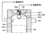
また、図4を参照して、シリンダブロック161の、シリンダボア161Aの内面のノックセンサ取付ボス163に対向する位置には、シリンダブロック振動測定器としてのシリンダブロック振動検出センサ310が配置されている。実機のエンジンにおいては、シリンダボア161A内には、上下に摺動するピストン164が配設され、シリンダブロック振動検出センサ310が配置される位置は、シリンダボアの内面の燃焼室Aに相当する領域に配置される。ノックセンサ取付ボス163は、精度良く形成されていることから、シリンダブロック161に対して、加振軸140を精度良く取付けることを可能としている。
Referring to FIG. 4, a cylinder block
図5を参照して、シリンダヘッド162に設けられたプラグ孔162pには、シリンダヘッド振動測定器としてのシリンダヘッド振動検出センサ320が配置され、このシリンダヘッド振動検出センサ320は、特殊ボルト301、金属キューブ302、および、センサ303から構成されている。より具体的な構成については、後述する。このプラグ孔162pは、図6に示すように、シリンダヘッド162に設けられる吸気バルブ孔162iと排気バルブ孔162eとに囲まれたシリンダヘッド162の中央領域に設けられている。また、このプラグ孔162pは、機械加工により、精度良く形成されていることから、シリンダヘッド162に対して、シリンダヘッド振動検出センサ320を精度良く取付けることを可能としている。
Referring to FIG. 5, a cylinder head
(ノッキング振動解析方法)
上記構成からなる振動伝達特性解析装置100を用いた、ノッキング発生時におけるエンジンブロック160の振動解析方法、具体的には、エンジンブロック160の振動伝達特性として、ノッキング信号(S:シリンダヘッドの振動特性)とノイズ信号(N:エンジンブロックの振動特性)とによるSN比を得る方法について説明する。まず、加振装置130を用いて、エンジンブロック160のノックセンサ取付ボス163に連結された加振軸140から、エンジンブロック160に所定の振動を加える。
(Knock vibration analysis method)
A vibration analysis method of the
次に、シリンダブロック振動検出センサ310およびシリンダヘッド振動検出センサ320を用いて、シリンダブロック161に生じる振動信号1およびシリンダヘッド162に生じる振動信号2をピックアップする。振動信号1および振動信号2は、コンピュータ200に入力され、エンジンブロック160のノッキング発生時における振動伝達特性(S/N比)が解析される。
Next, the vibration signal 1 generated in the
(振動伝達特性の具体的解析方法)
ここで、シリンダブロック振動検出センサ310およびシリンダヘッド振動検出センサ320を用いた振動伝達特性の具体的な解析方法について、図7および図8を参照して説明する。なお、図7は、シリンダブロック161に生じる振動およびシリンダヘッド162に生じる振動を図示した模式図であり、図8は、ノッキング発生点火時期における信号強度とノッキング発生頻度との関係を示す図である。
(Specific analysis method for vibration transfer characteristics)
Here, a specific analysis method of vibration transfer characteristics using the cylinder block
実機エンジンにおけるノッキング発生時のピストン164の位置は、図7に示すように、圧縮上死点後(ATDC)約10°〜60°の範囲にあるため、燃焼室A内のシリンダブロック161へ伝達する振動は、ピストン164によって抑制され、シリンダヘッド162からの振動伝達(S:ヘッド部振動応答)が支配的となる。一方、ピストン164の位置が低下すると、ピストン164によるシリンダブロック161の抑制が開放されて、シリンダブロック161が共振(N:ライナー部振動応答)を始める。
As shown in FIG. 7, the position of the
このシリンダブロック161の共振は、ノッキングの発生点火時期におけるエンジンノイズに影響を与え、ノイズ信号を大きくする結果、ノッキングセンサにおけるSN(ノッキング信号/ノイズ信号:ヘッド部振動応答S/ライナー部振動応答N)比に悪影響を与えることになる。つまり、図8に示すように、ノイズ信号Nが、ノイズ信号N’に移行する(強度が強くなる)ことで、ノッキング判定レベル(S)にノイズ信号が近づく結果、SN比を悪化させることになる。このように、ノッキングの発生点火時期におけるエンジンブロック160の横振動(初期振動)は、シリンダヘッド162からの振動伝達が支配的であり、シリンダブロック161からの信号がノイズ信号となる。
The resonance of the
そこで、本実施の形態における振動伝達特性解析装置100においては、シリンダブロック振動測定センサ310とシリンダヘッド振動測定センサ320との2種類の振動測定センサを燃焼室A内に配設することにより、加振装置130によりエンジンブロック160に所定の振動を与えた場合の応答信号をシリンダブロック振動測定センサ310およびシリンダヘッド振動測定センサ320によりピックアップすることで、シリンダブロック161の振動特性とシリンダヘッド162の振動特性、つまり、ノッキング信号(S:シリンダヘッドの振動特性)とノイズ信号(N:エンジンブロックの振動特性)とによるSN比を予め把握することができる。
Therefore, in the vibration transfer
(本振動伝達特性解析装置100によって得られたSN比と実機エンジンのSN比との相関関係について)
ここで、本振動伝達特性解析装置100によって得られたSN比と実機エンジンのSN比との相関関係について、図9および図10を参照して説明する。なお、図9は、本振動伝達特性解析装置100によって得られた各種エンジンと擬似SN比との関係を示す図であり、図10は、実際にエンジンを駆動させた状態での、各種エンジンにおける実機SN比合否を示す図である。
(Correlation between the SN ratio obtained by the vibration transfer
Here, the correlation between the SN ratio obtained by the vibration transfer
本振動伝達特性解析装置100によって得られたエンジンのノッキング発生時におけるSN比を擬似SN比と定義し、実際のエンジン駆動から得られたSN振動比を実機SN比と定義する。エンジン(A)、エンジン(B)、および、エンジン(C)より、擬似SN比と実機SN比とを比較した。
The SN ratio at the time of occurrence of engine knocking obtained by the vibration transfer
本振動伝達特性解析装置100を用いて、エンジン(A)、エンジン(B)、および、エンジン(C)の各エンジンブロックを用いて、各エンジンの擬似SN比を測定した結果、図9に示すように、エンジン(A)が最も制御性が良好な擬似SN比が得られ、次いで、エンジン(C)、エンジン(B)の順で、擬似SN比が得られた。
As a result of measuring the pseudo S / N ratio of each engine using the engine blocks of the engine (A), the engine (B), and the engine (C) using the vibration transfer
次に、エンジン(A)、エンジン(B)、および、エンジン(C)の各エンジンを実際に駆動させて、ノックセンサにより信号をピックアップして、実機SN比を測定した結果を、図10に示す。エンジン(A)およびエンジン(C)においては、合格のSN比が得られ、エンジン(B)においては、不合格のSN比が得られた。このように、擬似SN比が最も悪いエンジン(B)において、実機SN比も不合格の判定となり、本振動伝達特性解析装置100によって得られたSN比と実機エンジンのSN比との間に相関関係があることが証明された。
Next, the engine (A), engine (B), and engine (C) are actually driven, signals are picked up by knock sensors, and the actual SN ratio is measured. Show. In the engine (A) and the engine (C), an acceptable SN ratio was obtained, and in the engine (B), an unacceptable SN ratio was obtained. Thus, in the engine (B) with the worst pseudo S / N ratio, the actual machine S / N ratio is also judged to be unacceptable, and there is a correlation between the S / N ratio obtained by the vibration transfer
(シリンダヘッド振動検出センサ320の具体的構成)
次に、シリンダヘッド振動検出センサ320の具体的構成について、図11を参照して説明する。ここで、上述したようにシリンダヘッド振動検出センサ320においては、シリンダヘッド162に生じる横振動成分を正確に測定する必要があることから、その取付け位置、角度にも十分注意する必要がある。たとえば、シリンダヘッド162に対する取付け角度が不正確であれば、振動ベクトル方向の違いにより、測定誤差が生じることになる。そこで、本実施の形態においては、シリンダヘッド162に設けられたプラグ孔162pを用いて、シリンダヘッド振動検出センサ320を取付けている。
(Specific Configuration of Cylinder Head Vibration Detection Sensor 320)
Next, a specific configuration of the cylinder head
シリンダヘッド振動検出センサ320は、上述したように特殊ボルト301、金属キューブ302、および、センサ303から構成されている。ここで、特殊ボルト301へのセンサ303の取付けに際しても、取付け角度の正確性が要求されるため、機械加工により寸法精度が高精度に仕上げられた金属キューブ302(立方体形状)を、特殊ボルト301とセンサ303との間に介在させている。特殊ボルト301および金属キューブ302の材質は、測定誤差を生じさせない観点から、シリンダヘッド162と同素材で形成されていることが好ましい。
As described above, the cylinder head
特殊ボルト301への金属キューブ302の固定には、様々な固定構造が考えられる。図11(A)に示す接着剤を用いる固定構造、図11(B)に示す、特殊ボルト301側に雄ネジ305A、金属キューブ302側に雄ネジ305Aを受入れる雌ネジ305Bを設ける固定構造、図11(C)に示す、金属キューブ302側に雄ネジ305A、特殊ボルト301側に雄ネジ305Aを受入れる雌ネジ305Bを設ける固定構造、図11(D)に示す、独立した雄ネジ(スタッドボルト)305Aを準備し、特殊ボルト301および金属キューブ302のそれぞれに、雄ネジ305Aを受入れる雌ネジ305Bを設ける固定構造等が挙げられる。
Various fixing structures are conceivable for fixing the
なお、センサ303の取付け角度の正確性が要求されるため、平坦面を形成した金属キューブ302を設ける場合について説明したが、この取付け構造は、あくまでも一例であり、たとえば、シリンダヘッド162に対して、取付け角度の正確性を満足させることが可能な場合には、センサ303を直接シリンダヘッド162に取付ける固定構造の採用も可能である。
In addition, since the accuracy of the mounting angle of the
(加振位置の他の構成)
上記本振動伝達特性解析装置100においては、シリンダブロック161に対して(具体的には、シリンダボア161Aの内壁面に対して)、その加振方向が正確に垂直となるようにするため、また、シリンダブロック161への追加加工を不要とするために、既存のノックセンサ取付ボス163を用いて、このボス163に加振装置130の加振軸140が連結されている。しかし、シリンダブロック161への高い位置精度を確保して、取付け領域を設けることが問題にならない場合には、別途シリンダブロック161またはシリンダヘッド162に、加振軸140を連結するための領域を設けることも可能である。
(Other configurations of excitation position)
In the vibration transfer
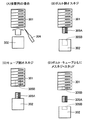
エンジンブロック160を加振させるための他の構成としては、図12に示すように、シリンダヘッド162を加振する方法が挙げられる。この加振方法においては、シリンダヘッド162に設けられたプラグ孔162pに加振のための加振用ボルト141を螺合させて、この加振用ボルト141に加振装置の加振部を連結させる。加振部の連結は、図12に示すように、外部から加振(矢印F1)する方法だけでなく、図13に示すように、加振用ボルト141を内部(燃焼室側)から加振(矢印F2)する方法も考えられる。なお、プラグ孔162pを利用する場合だけでなく、別途専用のボルト固定孔を形成することも可能である。
As another configuration for exciting the
また、エンジンブロック160を加振させるためのさらに他の構成としては、図14に示すように、シリンダブロック161の加振点P1とは反対側の側部にネジ孔161hを形成し、このネジ孔161hを利用して、加振用ボルト141の先端部を加振点P1に当接させて、エンジンブロック160を加振(矢印F3方向)させることも可能である。
Further, as another configuration for exciting the
また、エンジンブロック160を加振させるためのさらに他の構成としては、図15に示すように、シリンダブロック161の対向する両側のそれぞれにネジ孔161hを形成し、このネジ孔161hを利用して、加振用ボルト141をそれぞれのネジ孔161hの螺号させて、加振用ボルト141を加振(矢印F4,F5)する方法も考えられる。
Further, as another configuration for vibrating the
(作用・効果)
以上、本実施の形態におけるエンジンブロックの振動伝達特性解析装置100およびこの装置を用いた振動伝達特性解析方法によれば、シリンダブロック振動測定センサ310とシリンダヘッド振動測定センサ320との2種類の振動測センサを焼室内に配設し、加振装置130によりエンジンブロック160に所定の振動を与えた場合の応答信号を、シリンダブロック振動測定センサ310およびシリンダヘッド振動測定センサ320によりピックアップすることで、シリンダブロック161の振動特性とシリンダヘッド162の振動特性を把握することができる。その結果、エンジンブロック160の振動伝達特性として、ノッキング信号(S:シリンダヘッドの振動特性)とノイズ信号(N:エンジンブロックの振動特性)とによるSN比を得ることができる。
(実施の形態2)
以下、実施の形態2として、本発明に基づいたエンジンブロックの振動伝達特性解析装置に用いられる加振装置の構造について、図を参照しながら説明する。上記実施の形態1において述べたように、エンジンブロックの振動伝達特性解析装置100においては、S/N比を正確に測定するために、シリンダブロック161に対して、その加振方向が垂直となるように正確に加振する必要がある。そこで、一例として、既存のノックセンサ取付ボス163に加振装置130の加振軸140が連結されている。しかし、この加振軸140そのものにおいて、加振方向がずれるような問題が生じる場合には、ノックセンサ取付ボス163に取付けた場合であっても、正確な測定結果を得ることができないことになる。したがって、以下に示す加振軸140においては、そのような問題を生じさせない構造が採用されている。
(Action / Effect)
As described above, according to the vibration transmission
(Embodiment 2)
Hereinafter, as a second embodiment, a structure of a vibration exciter used in a vibration transfer characteristic analyzer for an engine block according to the present invention will be described with reference to the drawings. As described in the first embodiment, in the vibration transfer
以下、加振装置130に採用される加振軸140の具体的構成について、図16を参照して説明する。この加振軸140は、図16に示すように、加振ロッド145とアタッチメント146とから構成されている。アタッチメント146には、加振ロッド145を摺動可能に受入れるため、一端側が開放し、他端側に延びる有底の軸孔146hが設けられ、他端部は、加振装置130に連結されている。また、アタッチメント146の側面には、加振ロッド145を位置決め固定するため、軸孔146hに交差するネジ孔146sと、このネジ孔146sに螺合する固定ネジ146bとが設けられている。本実施の形態においては、加振ロッド145には丸棒が用いられ、軸孔146hには、この丸棒を収容可能な円筒形状の軸孔が形成されているが、特にこの形状に限定されるものではない。
Hereinafter, a specific configuration of the
加振ロッド145の一端は、被加振物であるエンジンブロック160に連結され、加振ロッド145の他端側は、アタッチメント146の軸孔146h内に収容され、その収容距離を調節することで、エンジンブロック160と加振装置130との間隔が調節可能に構成されている。両者の距離の調節が終了した段階で、固定ネジ146bが締め込まれ、アタッチメント146に対して加振ロッド145が固定されることになる。
One end of the
加振ロッド145は軸孔146h内に収容された状態で固定されるが、加振ロッド145の軸心と軸孔146hの軸心とがずれて固定された場合、加振装置130からの加振力およびその加振方向が正確に加振ロッド145に伝達されないことになる。エンジンブロック160に直接連結される加振ロッド145の軸心が、加振方向に対してθずれた場合の、加振力のベクトル方向を、図17に示す。加振方向がずれていない場合には、Y方向には、加振力の分力は発生しない。しかし、θずれることにより、Y方向に加振力の分力FYが発生する。このような分力FYが発生すると、被加振物であるエンジンブロック160に不必要な加振力を加えることになる。これにより、図18に示すように、本来の伝達特性に対して「共振点ピークのズレ」や、「共振周波数のズレ」を発生させる要因となる。その結果、上記エンジンブロックの振動伝達特性解析装置100においては、S/N比を正確に測定することができず、振動伝達特性解析装置100の信頼性を低下させることになる。
The
そこで、このような問題の発生を未然に解消すべく、本実施の形態における加振軸140においては、より好ましい形態として、図19に示すように、加振ロッド145のアタッチメント146の軸孔146h内への収容に際して、軸孔146hへの加振ロッド145の挿入時に生じる加振ロッド145に生じる角度(θ)を保証角度と定め、この角度が一定の角度以下となうように、加振ロッド145とアタッチメント146の軸孔146hとの関係を定めている。
Therefore, in order to eliminate the occurrence of such a problem, as shown in FIG. 19, in the
一例としては、図19に示すように、加振ロッド145を軸孔146h内に最大限収容し、かつ、加振ロッド145を軸孔146hに対して最大限傾斜させた状態での、軸孔146hの内壁面S1と、この内壁面S1に接する加振ロッド145の外壁面の母線S2とによって形成される角度を保証角度(θ)とし、この保証角度が、約0.382°以下となるように設定している。この角度以下となるように、加振ロッド145とアタッチメント146の軸孔146hとの関係を定めることで、加振ロッド145をエンジンブロック160に対して垂直方向に加振させることを可能としている。
As an example, as shown in FIG. 19, the shaft hole in the state in which the
保証角度を約0.382°以下とするための具体的な寸法としては、軸孔146hの開口部から、加振ロッド145の母線S2と軸孔146hの内壁面S1との交点までの距離L1が30mm、軸孔146hの開口部における加振ロッド145の母線S2から内壁面S1までの距離L2が200μmの場合には、tan−1(0.2/30)=0.382°となる。なお、この保証角度は、この数値に限定されるものではなく、測定すべき振動周波数(たとえば、20kHz等)によって、適宜定められるものである。
Specific dimensions for setting the guaranteed angle to about 0.382 ° or less include a distance L1 from the opening of the
(作用・効果)
以上、本実施の形態における加振装置130の加振軸140によれば、加振ロッド145とアタッチメント146との連結機構を採用していることにより、エンジンブロック160への連結作業の容易性、エンジンブロック160への連結位置決めの正確性を保つことが可能となる。また、加振軸140に採用される、軸孔146hへの加振ロッド145の挿入時に生じる保証角度(θ)を一定角度以下となるように、軸孔146hと加振ロッド145との間を規定することにより、加振ロッド145をエンジンブロック160に対して垂直方向に正確に加振させることが可能となる。
(Action / Effect)
As described above, according to the
なお、上記実施の形態においては、上記実施の形態1に示すエンジンブロックの振動伝達特性解析装置に用いられる加振機構について説明したが、これに限定されるものではなく、加振を必要とする装置全般に対して広く適用できるものである。 In the above embodiment, the vibration mechanism used in the engine block vibration transmission characteristic analyzer shown in the first embodiment has been described. However, the vibration mechanism is not limited to this and requires vibration. It can be widely applied to all devices.
したがって、今回開示した上記実施の形態はすべての点で例示であって、限定的な解釈の根拠となるものではない。したがって、本発明の技術的範囲は、上記した実施の形態のみによって解釈されるのではなく、特許請求の範囲の記載に基づいて画定される。また、特許請求の範囲と均等の意味および範囲内でのすべての変更が含まれる。 Accordingly, the above-described embodiment disclosed herein is illustrative in all respects and does not serve as a basis for limited interpretation. Therefore, the technical scope of the present invention is not interpreted only by the above-described embodiments, but is defined based on the description of the claims. Further, all modifications within the meaning and scope equivalent to the scope of the claims are included.
100 振動伝達特性解析装置、110 定盤、120 高精度高さ調節機構、121 ベース、121a ケース、121b,121c 楔部材、121d ハンドル、122 保持治具、123 U字溝、130 加振装置、131 支持ボルト、140 加振軸、141 加振用ボルト、145 加振ロッド、146 アタッチメント、146h 軸孔、146s ネジ孔、146b 固定ネジ、150 防振ゴム、161 シリンダブロック、161A シリンダボア、161h ネジ孔、160 エンジンブロック、162 シリンダヘッド、162e 排気バルブ孔、162i 吸気バルブ孔、162p プラグ孔、163 ノックセンサ取付ボス、164 ピストン、200 コンピュータ、301 特殊ボルト、302 金属キューブ、303 センサ、305A 雄ネジ、305B 雌ネジ、310 シリンダブロック振動検出センサ、320 シリンダヘッド振動検出センサ、A 燃焼室、P1 加振点、S1 内壁面、S2 母線。
DESCRIPTION OF
Claims (5)
前記シリンダボア(161A)内面の燃焼室(A)に相当する領域に配置されるシリンダブロック振動測定器(310)と、
前記燃焼室(A)に面し前記シリンダヘッド(162)の内面に配置されるシリンダヘッド振動測定器(320)と、
前記エンジンブロック(160)の所定位置に連結し前記エンジンブロック(160)に所定の振動を与えるための加振装置(130)と、を備えたことを特徴とするエンジンブロックの振動伝達特性解析装置。 An engine used for analyzing a vibration transmission characteristic of the engine block (160) by exciting an engine block (160) including a cylinder block (161) having a cylinder head (162) and a cylinder bore (161A). An apparatus for analyzing vibration transmission characteristics of a block,
A cylinder block vibration measuring device (310) disposed in a region corresponding to the combustion chamber (A) on the inner surface of the cylinder bore (161A);
A cylinder head vibration measuring device (320) facing the combustion chamber (A) and disposed on the inner surface of the cylinder head (162) ;
A vibration transmission characteristic analysis device for an engine block, comprising: a vibration exciter (130) coupled to a predetermined position of the engine block (160) to apply a predetermined vibration to the engine block (160) .
前記加振装置(130)は、前記ノックセンサ取付ボス(163)を利用して連結されたことを特徴とする、請求項1に記載のエンジンブロックの振動伝達特性解析装置。The vibration transmission characteristic analysis apparatus for an engine block according to claim 1, wherein the vibration exciter (130) is connected using the knock sensor mounting boss (163).
被加振物と前記加振装置(130)とを連結するように設けられる加振軸(140)を有し、前記被加振物を前記加振装置を用いて加振するための加振装置であって、
前記加振軸(140)は、
前記被加振物に連結される加振ロッド(145)と、
前記加振ロッド(145)を摺動可能に受入れるため、一端側が開放し他端側に延びる有底の軸孔(146h)が設けられ、他端側に前記加振装置(130)が連結されるアタッチメント(146)と、
前記アタッチメント(146)に前記加振ロッド(145)を固定するための固定手段(146b)と、
を備える、請求項1から3のいずれかに記載のエンジンブロックの振動伝達特性解析装置。 The vibration exciter (130)
An excitation shaft (140) provided to connect the object to be excited and the excitation device (130), and for exciting the object to be excited using the excitation device A device,
The excitation shaft (140)
An excitation rod (145) connected to the object to be excited ;
In order to slidably receive the excitation rod (145), a bottomed shaft hole (146h) that is open at one end and extends to the other end is provided, and the excitation device (130) is connected to the other end. Attachment (146)
Fixing means (146b) for fixing the excitation rod (145) to the attachment (146);
An engine block vibration transfer characteristic analyzer according to any one of claims 1 to 3, further comprising:
この保証角度が、所定角度以下となるように、前記加振ロッ(145)ドと前記アタッチメント(146)の軸孔(146h)との関係を定めたことを特徴とする、請求項4に記載のエンジンブロックの振動伝達特性解析装置。The relationship between the excitation lock (145) and the shaft hole (146h) of the attachment (146) is defined so that the guaranteed angle is equal to or less than a predetermined angle. For analyzing vibration transmission characteristics of engine blocks.
Priority Applications (1)
| Application Number | Priority Date | Filing Date | Title |
|---|---|---|---|
| JP2004076641A JP4244832B2 (en) | 2004-03-17 | 2004-03-17 | Engine block vibration transfer characteristic analyzer |
Applications Claiming Priority (1)
| Application Number | Priority Date | Filing Date | Title |
|---|---|---|---|
| JP2004076641A JP4244832B2 (en) | 2004-03-17 | 2004-03-17 | Engine block vibration transfer characteristic analyzer |
Publications (2)
| Publication Number | Publication Date |
|---|---|
| JP2005265541A JP2005265541A (en) | 2005-09-29 |
| JP4244832B2 true JP4244832B2 (en) | 2009-03-25 |
Family
ID=35090264
Family Applications (1)
| Application Number | Title | Priority Date | Filing Date |
|---|---|---|---|
| JP2004076641A Expired - Fee Related JP4244832B2 (en) | 2004-03-17 | 2004-03-17 | Engine block vibration transfer characteristic analyzer |
Country Status (1)
| Country | Link |
|---|---|
| JP (1) | JP4244832B2 (en) |
Families Citing this family (1)
| Publication number | Priority date | Publication date | Assignee | Title |
|---|---|---|---|---|
| JP4821555B2 (en) * | 2006-10-16 | 2011-11-24 | いすゞ自動車株式会社 | Simulated combustion shaker |
-
2004
- 2004-03-17 JP JP2004076641A patent/JP4244832B2/en not_active Expired - Fee Related
Also Published As
| Publication number | Publication date |
|---|---|
| JP2005265541A (en) | 2005-09-29 |
Similar Documents
| Publication | Publication Date | Title |
|---|---|---|
| JP2005300524A (en) | Vibration transmission property analyzer for engine block and vibration transmission property analysis method using above analyzer | |
| EP2156032B1 (en) | Method of mounting an accelerometer on an internal combustion engine and increasing signal-to-noise ratio | |
| Ahirrao et al. | Dynamics and vibration measurements in engines | |
| US8516895B2 (en) | In-cylinder pressure sensor diagnostic systems and methods | |
| CN1955750A (en) | Modal checking method and system of vacuum electronic device | |
| EP2184136A1 (en) | Method and equipment of control of detail connection by threaded joint | |
| Davis et al. | Cylinder pressure data quality checks and procedures to maximize data accuracy | |
| JP4244832B2 (en) | Engine block vibration transfer characteristic analyzer | |
| JP2009068964A (en) | Engine assembly balance measuring method, engine assembly production method using it, and engine assembly balance measuring apparatus | |
| JP4821555B2 (en) | Simulated combustion shaker | |
| CN109238452B (en) | Single-sensor pickup device based on impact echo acoustic frequency detection | |
| JP2008070302A (en) | Vibration transmission characteristics analyzer for engine block, and vibration transmission characteristics analysis method | |
| CN117309341A (en) | Cylinder liner fatigue testing device and cylinder liner testing method | |
| Storm et al. | Analysis of cylinder pressure measurement accuracy for internal combustion engine control | |
| JP2003003883A (en) | Method of detecting combustion condition of diesel engine | |
| JP4474327B2 (en) | Engine system design method and engine system designed by the design method | |
| Ravaglioli et al. | Torsional analysis of different powertrain configurations for torque and combustion phase evaluation | |
| Cavina et al. | Application of Acoustic and Vibration-Based Knock Detection Techniques to a High Speed Engine | |
| Schweighardt et al. | Modal Analysis of the Tubular Space Frame of a Formula Student Race Car | |
| JP6409688B2 (en) | Inspection method and manufacturing method of dynamic damper | |
| JP2008026062A (en) | Vibration transmission characteristic analyzer for engine block | |
| Andersson et al. | Detection of combustion properties in a diesel engine using block mounted accelerometers | |
| CN109975001B (en) | Modal testing device and method for crankshaft torsional vibration damper | |
| Gao et al. | Vibration Analysis of an Engine Cylinder Block | |
| JP6191029B2 (en) | In-cylinder combustion monitor sensor |
Legal Events
| Date | Code | Title | Description |
|---|---|---|---|
| A621 | Written request for application examination |
Free format text: JAPANESE INTERMEDIATE CODE: A621 Effective date: 20061222 |
|
| A977 | Report on retrieval |
Free format text: JAPANESE INTERMEDIATE CODE: A971007 Effective date: 20080703 |
|
| A131 | Notification of reasons for refusal |
Free format text: JAPANESE INTERMEDIATE CODE: A131 Effective date: 20080729 |
|
| A521 | Written amendment |
Free format text: JAPANESE INTERMEDIATE CODE: A523 Effective date: 20080925 |
|
| TRDD | Decision of grant or rejection written | ||
| A01 | Written decision to grant a patent or to grant a registration (utility model) |
Free format text: JAPANESE INTERMEDIATE CODE: A01 Effective date: 20081216 |
|
| A01 | Written decision to grant a patent or to grant a registration (utility model) |
Free format text: JAPANESE INTERMEDIATE CODE: A01 |
|
| A61 | First payment of annual fees (during grant procedure) |
Free format text: JAPANESE INTERMEDIATE CODE: A61 Effective date: 20081229 |
|
| R151 | Written notification of patent or utility model registration |
Ref document number: 4244832 Country of ref document: JP Free format text: JAPANESE INTERMEDIATE CODE: R151 |
|
| FPAY | Renewal fee payment (event date is renewal date of database) |
Free format text: PAYMENT UNTIL: 20120116 Year of fee payment: 3 |
|
| FPAY | Renewal fee payment (event date is renewal date of database) |
Free format text: PAYMENT UNTIL: 20130116 Year of fee payment: 4 |
|
| FPAY | Renewal fee payment (event date is renewal date of database) |
Free format text: PAYMENT UNTIL: 20130116 Year of fee payment: 4 |
|
| LAPS | Cancellation because of no payment of annual fees |