JP4242525B2 - Video / audio partial playback method and receiver in digital broadcasting - Google Patents
Video / audio partial playback method and receiver in digital broadcasting Download PDFInfo
- Publication number
- JP4242525B2 JP4242525B2 JP26913499A JP26913499A JP4242525B2 JP 4242525 B2 JP4242525 B2 JP 4242525B2 JP 26913499 A JP26913499 A JP 26913499A JP 26913499 A JP26913499 A JP 26913499A JP 4242525 B2 JP4242525 B2 JP 4242525B2
- Authority
- JP
- Japan
- Prior art keywords
- stc
- time
- standard time
- video
- itt
- Prior art date
- Legal status (The legal status is an assumption and is not a legal conclusion. Google has not performed a legal analysis and makes no representation as to the accuracy of the status listed.)
- Expired - Fee Related
Links
Images


Description
【0001】
【発明の属する技術分野】
本発明は、放送で送られてくる番組を一旦蓄積してから再生する受信装置において、番組の時間的な部分(シーン)を指定して再生する部分再生方法に関し、特に、指定された時間軸上の部分を正確に再生できるようにしたものである。
【0002】
【従来の技術】
デジタル放送の時代を迎え、放送で送られてくる番組を蓄積して、必要に応じて再生する受信装置、即ちホームサーバの研究開発が鋭意進められている。ホームサーバは、蓄積された番組の先頭から最後までを順に再生するだけでなく、番組のシーンを目次から選んで視聴したり、複数のシーンの再生順序を定義するシナリオに従って映像音声を視聴する、いわゆるノンリニア視聴を実現できる。
【0003】
ところで、我が国のデジタル放送では、国際標準規格であるMPEG−2 Systemsに基づいて、映像や音声が一旦PES(Packetized Elementary Stream)パケットに分割された後、TS(Transport Stream)パケットに多重化されて伝送される。この映像と音声とは、受信側で同期して再生する必要があり、そのため、映像、音声のそれぞれのPESパケットには、復号再生処理の基準となる時間STC(System Time Clock)(「同期基準時」と呼ぶことにする)を示すタイムスタンプが格納されている。
【0004】
実際の映像音声のデータに対してタイムスタンプが格納される場所は、PESヘッダの PTS(Presentation Time Stamp)/DTS(Decode Time Stamp)と呼ばれるフィールドである。図12は、PESヘッダ内のPTS/DTSの場所を表している。
【0005】
STCは、27MHz、42bitの時間軸であり、番組の管理に用いられる時、分、秒の形式の標準時の時間軸とは直接関係が無い。受信装置は、STCを発生するカウンタを具備しており、映像、音声の PTSの値がSTCの値に一致した時点で、その映像、音声をユーザに提示するように受信装置が制御され、それにより映像、音声の同期が実現される。
【0006】
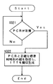
また、同期基準時であるSTCを、受信装置内と放送局とで同期させるために、PCR(Program Clock Reference)と呼ばれる情報がTSパケットのヘッダに格納されて伝送される。図10はTSパケットのデータ構造を示し、図11は、TSパケット内のPCRを含むアダプテーションフィールドのデータ構造を示している。このPCRは、現在のSTCの値を伝えるものであり、例えば1秒間に約10回の頻度で放送局から定期的に受信装置に伝送される。
【0007】
受信装置内では、定期的に伝送されてくるPCRに一致するようにPLL(PhaseLocked Loop)回路でカウンタの出力をリアルタイムに校正しながらSTCを生成出力する。
【0008】
図9は、このPLL回路のブロック図である。
【0009】
さて、受信装置に蓄積された番組に対するノンリニア視聴は、番組インデックスを用いて実現することができる。
【0010】
番組インデックスは、日本のデジタル放送の標準規格であるARIB STD−B10第1.2版において規定された、放送番組の選択や検索を補助する情報を提供する放送メタデータである。この番組インデックスはERT(Event Relation Table)とLIT(Localevent Information Table)というデータ構造であり、MPEG−2 Systemsで規定されるセクション形式の情報(以後、セクション情報と呼ぶ)として繰り返し放送される。
【0011】
番組インデックスは、放送で送られる映像音声を含む番組に対し、番組の時間的な一部分であるシーンを定義し(LIT)、シーン同士の関係を定義する(ERT)ことができる。シーンは、番組中におけるシーンの開始時間(start time)と持続時間(duration)とにより定義される。この番組管理のための時間は、時、分、秒の形式の標準時などが用いられる。
【0012】
しかし、デジタル放送における映像・音声は、国際標準規格であるMPEG−2 VideoやMPEG−1 Audioなどの圧縮された形式で伝送されるため、放送により伝送される映像音声の伝送形式と、再生結果の映像音声との間には不定長の遅延が生じる。このため、放送により伝送される映像音声の伝送形式上で、例えばフレーム精度(静止画フレーム間隔の精度、日本の場合約1/30秒)の時間精度でシーンの場所を決定することは容易ではない。従って、番組インデックスのLITによるシーン定義はミリ秒精度で記述できるものの、受信装置のシーンの再生においては秒程度の精度保証しかすることができない場合も想定できる。
【0013】
そこで、番組インデックスでは、シーンの再生を高い時間精度で行なうためにITT(Index Transmision Table:番組インデックス送出情報テーブル)という、セクション情報を定義している。
【0014】
このITTは、その中に、標準時による時間軸とSTCによる時間軸とを関連付ける情報を含んでおり、例えば、番組の開始時刻に該当するSTCの値がITTにより伝送される。STCの値は27,000,000分の1秒毎に1ずつ増加するので、このITTの情報を基に、番組に含まれる任意の時刻を、2つの時間軸の間で相互に換算することが可能となる。
【0015】
図13は、ITTのデータ構造を表した図である。図13の番組インデックス送出情報セクションのdescriptor(矢印)として、図14に示すSTC参照記述子が格納され、このSTC参照記述子において、秒及びミリ秒とSTCとの対応関係(矢印)が記述される。
【0016】
図15は、ITTの情報を用いて番組のシーンの再生を精密に行う例を説明している。番組インデックスには、番組の先頭が標準時により20:00'00"00(午後8時ちょうど)と定義され、また、あるシーンが、番組先頭を基準にした相対時刻で17'15"00〜17'31"00と定義されている。ITTにより、番組の先頭の20:00'00"00に対応するSTCの値(STC0)が与えられると、シーンの開始時刻をTs(=17'15"00)、シーンの終了時刻をTe(=17'31"00)とした場合、シーン開始のSTC(=STCs)は、
STCs=STC0+Ts×27×106
によって求めることができ、また、シーン終了のSTC(=STCe)は、
STCe=STC0+Te×27×106
によって求めることができる。
【0017】
このように、番組インデックスにおいて標準時で記述されているシーンの開始・終了時刻は、ITTの情報を用いることによって、STCの時間軸の値に換算することが可能になり、伝送形式のデータ上での正確な再生場所を特定することができる。
【0018】
受信装置は、換算した値STCs及びSTCeとPESパケットのPTSとを比較し、PTSがSTCsに一致する映像・音声から再生を開始し、PTSがSTCeに一致するところで再生を停止する。こうして、ITTによる精密時刻指定の方式を適用することにより、受信装置では、例えばフレーム精度でシーンの再生を行なうことが可能になる。ただし、PTSが十分な頻度で出現しない場合には別途PTSの補間の処理が必要になる場合もある。
【0019】
図7は、従来の受信装置(ホームサーバ)のブロック図を示している。この装置は、アンテナから成る受信手段000と、受信信号を復調する復調器001と、受信信号からAVストリーム、PCR、及びセクション情報を取り出すTSプロセッサ002と、PCRを基にSTCを生成するPLL003と、AVストリームが蓄積される、ハードディスクから成る蓄積手段006と、圧縮符号化されているAVデータを伸長復号化するデコーダ004と、映像・音声を提示(表示と発音)する提示手段005と、装置全体の動作を制御するCPU007と、セクション情報などを記憶するメモリ008とを備えている。
【0020】
この受信装置では、復調器001で復調された受信信号がLSIから成るTSプロセッサ002に入力し、TSプロセッサ002は、受信信号からAVストリーム、PCR及びセクション情報を取り出す。セクション情報には、番組インデックスやITTなどが含まれる。
【0021】
PCRが入力するPLL003は、図9の構成を備えており、PCRによって校正したSTCを出力する。TSプロセッサ002で分離されたAVストリームは、蓄積手段006に蓄積される。また、リアルタイム視聴の際は、AVストリームがデコーダ004に入力し、デコーダ004は、PESのPTSがSTCに一致する映像・音声データを復号化し、それにより映像・音声が同期して提示手段005から表示される。また、TSプロセッサ002で取り出された番組インデックスやITTの情報は蓄積手段006に蓄積される。
【0022】
図8には、この受信装置でノンリニア視聴する場合の動作を示している。図8(a)は、録画時の動作手順を示しており、
ステップ1:ユーザがEPG(電子番組表)から蓄積したい番組を指定すると、CPU007の制御の下に、
ステップ2:番組のオンエア開始を待って、
ステップ3:その番組のAVストリームが受信され、蓄積手段006への格納が開始される。
ステップ4:セクション情報に新しいITTがあれば取得してメモリ008に記録し、
ステップ5:AVストリームの受信と蓄積手段006への格納とを継続し、
ステップ6:番組のオンエアが終了するまで、それが繰り返される。
【0023】
図8(b)は、受信装置で番組の特定のシーンを視聴する場合の動作について示している。
【0024】
ステップ11:ユーザが、番組インデックスに基づくシーン一覧表示から、視聴したいシーンを指定すると、
ステップ12:CPU007は、メモリ008からITTの情報を読み出して、指定されたシーンの開始時刻をITTによりSTCの時間軸に変換し、
ステップ13:また、指定されたシーンの終了時刻をITTによりSTCの時間軸に変換する。
【0025】
ステップ14:蓄積手段006に蓄積されたAVストリームから、シーン開始時刻のSTCに対応する場所を検索し、
ステップ15:検索した場所からのAVストリームの再生をデコーダ004に指示し、
ステップ16:デコーダ004は、AVデータの再生処理を行い、
ステップ17:終了時刻まで再生を続ける。
【0026】
このように、ITTを用いることにより、高い精度でシーンを再生することが可能になる。
【0027】
【発明が解決しようとする課題】
しかし、従来のシーン再生方法では、ITTの情報が存在しない場合に、シーンを高精度に再生することができなくなる。ITTが存在しない状況としては、以下の様な場合が想定できる。
・ITTを送出しない番組を蓄積の対象とした場合。
・番組は開始しているものの、まだ、放送局からITTが送られてきていない場合。
・ザッピング視聴(チャンネルを頻繁に切り換える視聴)や降雨による電波の減衰などのためにITTの受信に失敗した場合。
【0028】
ITTが存在しない状態でシーンを再生するには、番組インデックスに示されている標準時を基準にシーンを特定しなければならないが、伝送遅延などが存在するため、その標準時にそのシーンが受信装置に受信されていたかどうかは不確かであり、また、AVストリームの受信から蓄積までの時間は受信装置の性能によってまちまちである。そのため、標準時を単純に用いるだけではシーンを高精度に特定することは不可能である。その結果、再生したシーンの冒頭や末尾に前後のシーンの映像や音声が混入したり、指定したシーンの映像や音声の一部が欠けたりして、視聴者に違和感や不快感を与えることになる。
【0029】
本発明は、こうした従来の問題点を解決するものであり、ITTが存在していない状況においても、ITTが存在する場合に比較的近い時間精度でシーンの再生を実現することができる映像音声の部分再生方法と、その方法を実施する受信装置とを提供することを目的としている。
【0030】
【課題を解決するための手段】
本発明は、デジタル放送で受信したTSトランスポートストリームに含まれる映像音声の指定された部分を再生する受信装置での映像音声の部分再生方法において、受信装置の実時間時計が計時する実時間を標準時として取得するステップと、前記TSトランスポートストリームにより定期的に送られてくるPCRから復号再生処理の基準となる時間であるSTCを取得・生成するステップと、同じ瞬間の前記標準時と前記STCとを取得するステップと、前記ステップで取得した同一瞬間の前記標準時と前記STCとの組を用いて、番組開始の標準時をSTCに換算した疑似ITTを生成するステップと、前記映像音声の指定された部分をSTCに基づいて再生するステップと、を備えることを特徴とする。
【0031】
また、デジタル放送で受信したTSトランスポートストリームに含まれる映像音声の指定された部分を再生する受信装置において、標準時を計時する実時間時計と、前記TSトランスポートストリームにより定期的に送られてくるPCRにより表されるSTCと一致するように校正しながら復号再生処理の基準となる時間である前記STCを生成するPLLと、同じ瞬間の前記標準時と前記STCとを取得し、この同一瞬間の前記標準時と前記STCとの組を用いて、番組開始の標準時をSTCに換算した疑似ITTを生成する疑似ITT生成手段と、前記映像音声の指定された部分をSTCに基づいて再生する再生手段と、
を備えることを特徴とする。
【0032】
そのため、PLLが出力するSTCの値、または、伝送されてくるPCRのSTCの値と、標準時を刻む実時間時計の値とを比較することで、ITTに格納される情報に相当する値を受信装置内で疑似的に生成することができ、この値をITTの情報の代わりに用いることによって、高い精度でシーンの再生を実現することができる。
【0033】
【発明の実施の形態】
(第1の実施形態)
第1の実施形態における受信装置は、図1に示すように、アンテナから成る受信手段000と、受信信号をデジタル信号に変換する復調器001と、受信信号からAVストリーム、PCR、及びセクション情報を取り出すTSプロセッサ002と、PCRを基にSTCを生成するPLL003と、AVストリームが蓄積される蓄積手段006と、圧縮符号化されているAVデータを伸長復号化するデコーダ004と、映像・音声を表示する提示手段005と、装置全体の動作を制御するCPU007と、セクション情報を記憶するメモリ008と、標準時を計時する実時間時計402と、疑似ITTを生成する疑似ITT生成手段401とを備えている。
【0034】
この装置の実時間時計402は、秒単位の分解能で出力が可能である。また、疑似ITT生成手段401には、PLL003から出力されるSTCの値と、実時間時計402から出力される標準時とが入力し、疑似ITT生成手段401は、同じ瞬間に入力する標準時とSTCの値との組からITTのデータを疑似的に生成する。
【0035】
生成された疑似ITTのデータはメモリ008に蓄積され、AVストリームからシーンを特定して再生する場合に、受信するITTの代替として利用される。
【0036】
図2(a)は、この装置において、番組を蓄積する場合の動作について示している。
【0037】
ステップ1:ユーザがEPG(電子番組表)から蓄積したい番組を指定すると、CPU007の制御の下に、
ステップ2:番組のオンエア開始を待って、
ステップ3:その番組のAVストリームが受信され、蓄積手段006への格納が開始される。
ステップ301:疑似ITT生成手段401は、STCと標準時時刻との組を取得してITTを模擬生成し、生成した疑似ITTをメモリ008に記録する。
【0038】
ステップ5:AVストリームの受信と蓄積手段006への格納とが継続され、
ステップ6:番組のオンエア終了まで、ステップ005が繰り返される。
【0039】
ステップ301における疑似ITTの生成は、図2(b)に示すように、
ステップ311:実時間時計402の計時する標準時が次の値に変化したとき、
ステップ312:PLL003から出力されたSTCを取得し、その標準時時刻とSTCとの組からITTを疑似生成する。
【0040】
図3は、疑似的にITTを生成する具体例を図示している。PLL003は、図9の構成を備えており、1秒間に約10回程度の頻度で入力するPCRによって校正しながら、27,000,000分の1秒毎に1ずつ増加するSTCを生成し出力する。秒単位で標準時を計時する実時間時計102の時刻が、20:32'48"から20:32'49"に変化したとき、その時点t1でPLL003から出力されたSTCの値(STC_t1)を取り込み、標準時20:32'49"とSTC_t1との関係からITTを疑似生成する。
【0041】
このとき、実時間時計102より取り込んだ標準時時刻(Tt1)が番組の開始時刻(T0:この番組開始の標準時時刻は電子番組表の情報から把握することができる。)に一致するときは、取り込んだSTCの値(STC_t1)を番組開始時刻T0に対応するSTCの値(STC0)としてメモリ008に記録する。
【0042】
また、実時間時計102より取り込んだ標準時時刻(Tt1)が番組開始時刻T0と異なるときは、STC0を次式により求め、疑似ITTの情報としてメモリ008に記録する。ただし、標準時時刻Tt1、T0は秒を単位として記述されているものとする。
【0043】
STC0=(STC_t1)−(Tt1−T0)×27×106
このように、同一瞬時の標準時とSTCとの組から疑似ITTを生成して保持することにより、ITTが存在しない場合でも、映像音声ストリームの中の再生する部分をPTSによって特定することが可能になり、フレーム精度に近い精度でシーンを特定して再生することができる。
【0044】
(第2の実施形態)
第2の実施形態では、PCRと標準時時刻とを取り込んで疑似ITTを生成する場合について説明する。
【0045】
この受信装置は、図4に示すように、1/100秒の分解能で出力が可能な実時間時計102と、TSプロセッサ002から出力されるPCRと実時間時計102から出力される標準時とを基に疑似ITTを生成する疑似ITT生成手段101とを具備している。その他の構成は第1の実施形態と変わりがない。
【0046】
この装置において、番組を蓄積する場合の動作は、図2(a)の手順と変わりがない。ただ、STCと標準時時刻との組を取得してITTを疑似生成するステップ301の具体的動作は、図5のようになる。
【0047】
ステップ321:TSプロセッサ002から新たなPCRが出力されるのを待ち、PCRが出力されると、
ステップ322:その時点の実時間時計102における時刻を取得し、その標準時時刻と、PCRで表されたSTCの値との組からITTを疑似生成する。
【0048】
図6は、疑似的にITTを生成する具体例を図示している。TSプロセッサ002からPCR#5が出力されると、その時点t2の実時間時計102の時刻20:32'49"72を取り込み、PCR#5で表されたSTCの値と時刻20:32'49"72とから疑似ITTを生成する。
【0049】
このとき、実時間時計402より取り込んだ標準時時刻をTt2、取り込んだPCRが表しているSTCの値を(STC_t2)とすると、番組開始時刻T0に対応するSTCの値(STC0)は、
STC0=(STC_t2)−(Tt2−T0)×27×106
により求めることができる。
【0050】
このように、ITTが存在しない場合でも、PCRが到着した瞬間の標準時を計測することによって疑似ITTを生成し保持することができ、第1の実施形態と同様、映像音声ストリームの中の再生する部分をPTSによって特定することが可能になる。
【0051】
【発明の効果】
以上の説明から明らかなように、本発明によれば、番組インデックスにより高い時間精度でシーンの再生を実現するための情報であるITTが受信装置に存在しない場合でも、ITTが存在している場合と比較的近い精度でシーンの再生を実現することができる。
【図面の簡単な説明】
【図1】第1の実施形態における受信装置の構成を示すブロック図、
【図2】第1の実施形態における受信装置の映像音声蓄積時の動作(a)と、疑似ITT生成の動作(b)を示すフロー図、
【図3】第1の実施形態における実時間とSTCとの組の取得方法を示す図、
【図4】第2の実施形態における受信装置の構成を示すブロック図、
【図5】第2の実施形態における疑似ITT生成の動作を示すフロー図、
【図6】第2の実施形態における実時間とSTCとの組の取得方法を示す図、
【図7】従来の受信装置の構成を示すブロック図、
【図8】従来の受信装置による番組蓄積動作(a)と、シーン再生動作(b)を示すフロー図、
【図9】PLL回路のブロック図、
【図10】TSパケットのデータ構造を示す図、
【図11】TSパケットのPCRが格納されるアダプテーションフィールドのデータ構造を示す図、
【図12】PTS/DTSの格納場所を示すPESヘッダのデータ構造を示す図、
【図13】ITTのデータ構造を示す図、
【図14】STC参照記述子のデータ構造を示す図、
【図15】ITTによる精密時刻指定の一例を示す図である。
【符号の説明】
000 受信手段
001 復調器
002 TSプロセッサ
003 PLL
004 デコーダ
005 提示手段
006 蓄積手段
007 CPU
008 メモリ
101、401 疑似ITT生成手段
102、402 実時間時計[0001]
BACKGROUND OF THE INVENTION
The present invention relates to a partial reproduction method for designating and reproducing a temporal portion (scene) of a program in a receiving apparatus that once accumulates and reproduces a program sent by broadcasting, and in particular, a designated time axis. The upper part can be reproduced accurately.
[0002]
[Prior art]
In the era of digital broadcasting, research and development of a receiving apparatus, that is, a home server, that accumulates programs transmitted by broadcasting and reproduces them as necessary has been advanced. The home server not only plays the stored program from the beginning to the end in order, but also selects and views the program scenes from the table of contents, and watches the video and audio according to a scenario that defines the playback order of multiple scenes. So-called non-linear viewing can be realized.
[0003]
By the way, in Japanese digital broadcasting, video and audio are once divided into PES (Packetized Elementary Stream) packets based on the international standard MPEG-2 Systems, and then multiplexed into TS (Transport Stream) packets. Is transmitted. This video and audio must be played back synchronously on the receiving side. Therefore, each PES packet of video and audio has a time STC (System Time Clock) (“synchronization reference” as a reference for decoding and playback processing). A time stamp indicating “time” is stored.
[0004]
The place where the time stamp is stored for the actual video / audio data is a field called PTS (Presentation Time Stamp) / DTS (Decode Time Stamp) in the PES header. FIG. 12 shows the location of the PTS / DTS in the PES header.
[0005]
The STC is a time axis of 27 MHz and 42 bits, and is not directly related to the time axis of the standard time in the hour, minute, and second format used for program management. The receiving device includes a counter that generates an STC. When the video and audio PTS values match the STC value, the receiving device is controlled to present the video and audio to the user. Thus, synchronization of video and audio is realized.
[0006]
Also, in order to synchronize STC, which is the synchronization reference time, between the receiving apparatus and the broadcasting station, information called PCR (Program Clock Reference) is stored in the header of the TS packet and transmitted. FIG. 10 shows the data structure of the TS packet, and FIG. 11 shows the data structure of the adaptation field including the PCR in the TS packet. This PCR conveys the current STC value, and is periodically transmitted from the broadcast station to the receiving apparatus at a frequency of about 10 times per second, for example.
[0007]
In the receiving apparatus, an STC is generated and output while the counter output is calibrated in real time by a PLL (Phase Locked Loop) circuit so as to match the PCR transmitted periodically.
[0008]
FIG. 9 is a block diagram of this PLL circuit.
[0009]
Now, non-linear viewing of programs stored in the receiving apparatus can be realized using a program index.
[0010]
The program index is broadcast metadata that provides information for assisting selection and search of a broadcast program defined in ARIB STD-B10 Version 1.2, which is a standard for digital broadcasting in Japan. This program index has a data structure of ERT (Event Relation Table) and LIT (Local Event Information Table), and is repeatedly broadcast as section format information (hereinafter referred to as section information) defined in MPEG-2 Systems.
[0011]
The program index can define a scene that is a temporal part of a program (LIT) and a relationship between scenes (ERT) for a program including video and audio transmitted by broadcasting. A scene is defined by the start time (start time) and duration (duration) of the scene in the program. As the time for program management, standard time in the form of hour, minute, second is used.
[0012]
However, since video / audio in digital broadcasting is transmitted in a compressed format such as MPEG-2 Video or MPEG-1 Audio, which are international standards, the transmission format of video / audio transmitted by broadcasting and the reproduction result An indefinite length of delay occurs between the video and audio. For this reason, it is not easy to determine the location of a scene with time accuracy of, for example, frame accuracy (accuracy of still image frame interval, approximately 1/30 second in Japan) on the transmission format of video and audio transmitted by broadcasting. Absent. Therefore, although the scene definition by the LIT of the program index can be described with millisecond accuracy, it can be assumed that accuracy of only about seconds can be assured when reproducing the scene of the receiving apparatus.
[0013]
Therefore, in the program index, section information called ITT (Index Transmision Table) is defined in order to perform scene reproduction with high time accuracy.
[0014]
The ITT includes information for associating the time axis based on the standard time and the time axis based on the STC. For example, the value of the STC corresponding to the start time of the program is transmitted by the ITT. Since the STC value increases by 1 every 27,000,000th of a second, any time included in the program can be converted between two time axes based on this ITT information. Is possible.
[0015]
FIG. 13 shows the data structure of ITT. The STC reference descriptor shown in FIG. 14 is stored as the descriptor (arrow) in the program index transmission information section of FIG. 13, and the correspondence (arrow) between the second and millisecond and the STC is described in this STC reference descriptor. The
[0016]
FIG. 15 illustrates an example of precisely reproducing a program scene using ITT information. In the program index, the beginning of the program is defined as 20: 00'00 "00 (exactly 8:00 pm) by standard time, and a certain scene is 17'15" 00-17 in relative time with respect to the beginning of the program. It is defined as '31 "00. When the STC value (STC 0 ) corresponding to the top 20: 00'00" 00 of the program is given by ITT, the scene start time is set to Ts (= 17'15 “00), when the scene end time is Te (= 17'31” 00), the STC at the start of the scene (= STCs) is
STCs = STC 0 + Ts × 27 × 10 6
The STC at the end of the scene (= STCe) is
STCe = STC 0 + Te × 27 × 10 6
Can be obtained.
[0017]
As described above, the scene start / end times described in the standard time in the program index can be converted into STC time-axis values by using ITT information. The exact playback location can be specified.
[0018]
The receiving device compares the converted values STCs and STCe with the PTS of the PES packet, starts playback from the video / audio whose PTS matches STCs, and stops playback when the PTS matches STCe. Thus, by applying the precise time designation method using ITT, the receiving apparatus can reproduce the scene with, for example, frame accuracy. However, if PTS does not appear with sufficient frequency, PTS interpolation processing may be required separately.
[0019]
FIG. 7 shows a block diagram of a conventional receiving apparatus (home server). This apparatus includes a receiving unit 000 including an antenna, a
[0020]
In this receiving apparatus, the received signal demodulated by the
[0021]
The
[0022]
FIG. 8 shows an operation in the case of nonlinear viewing with this receiving apparatus. FIG. 8A shows an operation procedure during recording.
Step 1: When the user designates a program to be stored from the EPG (electronic program guide), under the control of the
Step 2: Wait for the program to start on air,
Step 3: The AV stream of the program is received, and storage in the storage means 006 is started.
Step 4: If there is a new ITT in the section information, obtain it and record it in the
Step 5: Continue receiving the AV stream and storing it in the storage means 006,
Step 6: It is repeated until the program is on air.
[0023]
FIG. 8B shows an operation when a specific scene of a program is viewed on the receiving apparatus.
[0024]
Step 11: When the user specifies a scene to view from the scene list display based on the program index,
Step 12: The
Step 13: Also, the end time of the designated scene is converted to the STC time axis by ITT.
[0025]
Step 14: Search the location corresponding to the STC at the scene start time from the AV stream stored in the storage means 006,
Step 15: Instruct the
Step 16: The
Step 17: Continue playback until the end time.
[0026]
As described above, by using ITT, a scene can be reproduced with high accuracy.
[0027]
[Problems to be solved by the invention]
However, the conventional scene reproduction method cannot reproduce the scene with high accuracy when there is no ITT information. As a situation where ITT does not exist, the following cases can be assumed.
・ When programs that do not send ITT are stored.
・ The program has started, but ITT has not yet been sent from the broadcasting station.
・ When ITT reception fails due to zapping viewing (watching frequently switching channels) or radio wave attenuation due to rain.
[0028]
In order to play a scene in the absence of ITT, the scene must be specified based on the standard time indicated in the program index. However, since there is a transmission delay, the scene is transmitted to the receiving device at the standard time. It is uncertain whether it has been received, and the time from reception to storage of the AV stream varies depending on the performance of the receiving apparatus. Therefore, it is impossible to specify a scene with high accuracy by simply using the standard time. As a result, the video and audio of the preceding and following scenes may be mixed at the beginning and end of the reproduced scene, or part of the video and audio of the specified scene may be lost, giving the viewer a sense of discomfort and discomfort. Become.
[0029]
The present invention solves such a conventional problem, and even in a situation where the ITT does not exist, a video / audio that can realize scene reproduction with a time accuracy relatively close to that when the ITT exists is provided. An object of the present invention is to provide a partial reproduction method and a receiving apparatus that implements the method.
[0030]
[Means for Solving the Problems]
The present invention relates to a video / audio partial playback method in a receiver for reproducing a specified portion of video / audio included in a TS transport stream received by digital broadcasting, and the real time clocked by the real-time clock of the receiver is used. A step of acquiring as standard time, a step of acquiring and generating STC, which is a reference time for decoding and reproducing processing, from PCR periodically sent by the TS transport stream, and the standard time and STC at the same moment acquiring, using the same set and moment the standard time and the STC obtained in step, and generating a pseudo ITT obtained by converting the standard time of program start to STC, which is designated the audiovisual And replaying the part based on STC .
[0031]
Also, in a receiving apparatus that reproduces a designated portion of video and audio included in a TS transport stream received by digital broadcasting, a real-time clock that measures standard time and the TS transport stream are periodically sent. It gets a PLL that generates the STC is a time serving as a reference of decoding and reproduction process while calibrated to match the STC represented by PCR, the standard time of the same moment as the said STC, said the same moment using a set of the standard time and the STC, the pseudo ITT generating means for generating a pseudo ITT obtained by converting the standard time of program start to STC, and reproducing means for reproducing based on a specified portion of the video and audio to STC,
It is characterized by providing.
[0032]
Therefore, a value corresponding to the information stored in the ITT is received by comparing the STC value output by the PLL or the STC value of the transmitted PCR with the value of the real-time clock that ticks the standard time. It can be generated in a pseudo manner in the apparatus, and by using this value instead of ITT information, it is possible to realize scene reproduction with high accuracy.
[0033]
DETAILED DESCRIPTION OF THE INVENTION
(First embodiment)
As shown in FIG. 1, the receiving apparatus in the first embodiment includes a receiving unit 000 including an antenna, a
[0034]
The real-
[0035]
The generated pseudo ITT data is stored in the
[0036]
FIG. 2 (a) shows the operation when a program is stored in this apparatus.
[0037]
Step 1: When the user designates a program to be stored from the EPG (electronic program guide), under the control of the
Step 2: Wait for the program to start on air,
Step 3: The AV stream of the program is received, and storage in the storage means 006 is started.
Step 301: The pseudo ITT generating means 401 acquires a set of STC and standard time, generates ITT by simulation, and records the generated pseudo ITT in the
[0038]
Step 5: Reception of the AV stream and storage in the storage means 006 are continued,
Step 6: Step 005 is repeated until the program ends on air.
[0039]
The pseudo ITT generation in
Step 311: When the standard time measured by the
Step 312: The STC output from the PLL003 is acquired, and an ITT is pseudo-generated from the set of the standard time and the STC.
[0040]
FIG. 3 illustrates a specific example of generating ITT in a pseudo manner. The
[0041]
At this time, when the standard time (Tt1) fetched from the real-
[0042]
When the standard time (Tt1) taken from the
[0043]
STC 0 = (STC_t1) − (Tt1−T 0 ) × 27 × 10 6
In this way, by generating and holding a pseudo ITT from a set of standard time and STC at the same instant, even if no ITT exists, it is possible to specify a portion to be reproduced in the video / audio stream by PTS. Thus, the scene can be identified and reproduced with an accuracy close to the frame accuracy.
[0044]
(Second Embodiment)
In the second embodiment, a case where pseudo ITT is generated by taking in PCR and standard time will be described.
[0045]
As shown in FIG. 4, this receiving apparatus is based on a
[0046]
In this apparatus, the operation for storing a program is not different from the procedure in FIG. However, the specific operation of
[0047]
Step 321: Wait for a new PCR to be output from the
Step 322: The time in the real-
[0048]
FIG. 6 shows a specific example of generating ITT in a pseudo manner. When the
[0049]
At this time, if the standard time acquired from the
STC 0 = (STC_t2) − (Tt2−T 0 ) × 27 × 10 6
It can ask for.
[0050]
As described above, even when there is no ITT, the pseudo ITT can be generated and held by measuring the standard time at the moment when the PCR arrives, and is reproduced in the video / audio stream as in the first embodiment. The part can be specified by PTS.
[0051]
【The invention's effect】
As is clear from the above description, according to the present invention, even when ITT, which is information for realizing scene reproduction with high time accuracy by the program index, does not exist in the receiving apparatus, it exists. It is possible to realize scene playback with relatively close accuracy.
[Brief description of the drawings]
FIG. 1 is a block diagram illustrating a configuration of a receiving device according to a first embodiment;
FIG. 2 is a flowchart showing an operation (a) at the time of video / audio accumulation and an operation (b) of pseudo ITT generation in the receiving apparatus according to the first embodiment;
FIG. 3 is a diagram showing a method for acquiring a set of real time and STC in the first embodiment;
FIG. 4 is a block diagram showing a configuration of a receiving device in the second embodiment;
FIG. 5 is a flowchart showing an operation of generating pseudo ITT in the second embodiment;
FIG. 6 is a diagram showing a method for acquiring a set of real time and STC in the second embodiment;
FIG. 7 is a block diagram showing a configuration of a conventional receiving device;
FIG. 8 is a flowchart showing a program storage operation (a) and a scene reproduction operation (b) by a conventional receiving device;
FIG. 9 is a block diagram of a PLL circuit;
FIG. 10 is a diagram showing a data structure of a TS packet;
FIG. 11 is a diagram showing a data structure of an adaptation field in which a PCR of a TS packet is stored;
FIG. 12 is a diagram showing a data structure of a PES header indicating a storage location of PTS / DTS;
FIG. 13 is a diagram showing a data structure of ITT;
FIG. 14 is a diagram showing a data structure of an STC reference descriptor;
FIG. 15 is a diagram showing an example of precise time designation by ITT.
[Explanation of symbols]
000 means of receiving
001 demodulator
002 TS processor
003 PLL
004 decoder
005 Presentation means
006 Accumulation means
007 CPU
008 memory
101, 401 Pseudo ITT generation means
102, 402 Real time clock
Claims (6)
受信装置の実時間時計が計時する実時間を標準時として取得するステップと、
前記TSトランスポートストリームにより定期的に送られてくるPCR( Program Clock Reference )から復号再生処理の基準となる時間であるSTC( System Time Clock )を取得・生成するステップと、
同じ瞬間の前記標準時と前記STCとを取得するステップと、
前記ステップで取得した同一瞬間の前記標準時と前記STCとの組を用いて、番組開始の標準時をSTCに換算した疑似ITT( Index Transmission Table )を生成するステップと、
前記映像音声の指定された部分をSTCに基づいて再生するステップと、
を備えることを特徴とする映像音声の部分再生方法。In a video / audio partial playback method in a receiving apparatus for playing back a specified portion of video / audio included in a TS transport stream received by digital broadcasting,
Obtaining the real time measured by the real time clock of the receiving device as standard time;
Obtaining and generating an STC ( System Time Clock ) which is a reference time for decoding and reproducing processing from a PCR ( Program Clock Reference ) periodically sent by the TS transport stream ;
Obtaining the standard time and the STC at the same moment;
Generating a using the set of same instantaneous of the standard time and the STC obtained in step, the pseudo obtained by converting the standard time of program start the STC ITT (Index Transmission Table),
Replaying a designated portion of the video and audio based on STC ;
A method of partially reproducing video and audio, comprising:
標準時を計時する実時間時計と、A real time clock that measures standard time,
前記TSトランスポートストリームにより定期的に送られてくるPCRにより表されるSTCと一致するように校正しながら復号再生処理の基準となる時間である前記STCを生成するPLLと、A PLL that generates the STC, which is a reference time for decoding and reproduction processing while calibrating to match the STC represented by the PCR periodically sent by the TS transport stream;
同じ瞬間の前記標準時と前記STCとを取得し、この同一瞬間の前記標準時と前記STCとの組を用いて、番組開始の標準時をSTCに換算した疑似ITTを生成する疑似ITT生成手段と、Pseudo ITT generating means for acquiring the standard time and the STC at the same moment, and using the set of the standard time and the STC at the same moment, generating a pseudo ITT in which the standard time of the program start is converted into an STC;
前記映像音声の指定された部分をSTCに基づいて再生する再生手段と、Playback means for playing back a designated portion of the video and audio based on STC;
を備えることを特徴とする受信装置。A receiving apparatus comprising:
Priority Applications (1)
| Application Number | Priority Date | Filing Date | Title |
|---|---|---|---|
| JP26913499A JP4242525B2 (en) | 1999-09-22 | 1999-09-22 | Video / audio partial playback method and receiver in digital broadcasting |
Applications Claiming Priority (1)
| Application Number | Priority Date | Filing Date | Title |
|---|---|---|---|
| JP26913499A JP4242525B2 (en) | 1999-09-22 | 1999-09-22 | Video / audio partial playback method and receiver in digital broadcasting |
Publications (2)
| Publication Number | Publication Date |
|---|---|
| JP2001094945A JP2001094945A (en) | 2001-04-06 |
| JP4242525B2 true JP4242525B2 (en) | 2009-03-25 |
Family
ID=17468176
Family Applications (1)
| Application Number | Title | Priority Date | Filing Date |
|---|---|---|---|
| JP26913499A Expired - Fee Related JP4242525B2 (en) | 1999-09-22 | 1999-09-22 | Video / audio partial playback method and receiver in digital broadcasting |
Country Status (1)
| Country | Link |
|---|---|
| JP (1) | JP4242525B2 (en) |
Cited By (1)
| Publication number | Priority date | Publication date | Assignee | Title |
|---|---|---|---|---|
| US20130193344A1 (en) * | 2010-11-24 | 2013-08-01 | Khs Gmbh | Device for sterilizing closures for containers |
Families Citing this family (1)
| Publication number | Priority date | Publication date | Assignee | Title |
|---|---|---|---|---|
| US6900549B2 (en) * | 2001-01-17 | 2005-05-31 | Micron Technology, Inc. | Semiconductor assembly without adhesive fillets |
-
1999
- 1999-09-22 JP JP26913499A patent/JP4242525B2/en not_active Expired - Fee Related
Cited By (3)
| Publication number | Priority date | Publication date | Assignee | Title |
|---|---|---|---|---|
| US20130193344A1 (en) * | 2010-11-24 | 2013-08-01 | Khs Gmbh | Device for sterilizing closures for containers |
| US8884249B2 (en) | 2010-11-24 | 2014-11-11 | Khs Gmbh | Device for sterilizing closures for containers |
| DE102010052207B4 (en) | 2010-11-24 | 2017-08-31 | Khs Gmbh | Device for sterilizing closures for containers |
Also Published As
| Publication number | Publication date |
|---|---|
| JP2001094945A (en) | 2001-04-06 |
Similar Documents
| Publication | Publication Date | Title |
|---|---|---|
| US7428696B2 (en) | System and method for time synchronization between multimedia content and segment metadata | |
| US8204366B2 (en) | Method, apparatus and program for recording and playing back content data, method, apparatus and program for playing back content data, and method, apparatus and program for recording content data | |
| JP5903924B2 (en) | Receiving apparatus and subtitle processing method | |
| US8290353B2 (en) | Data processing device and method | |
| JP4740468B2 (en) | Method and apparatus for recording or reproducing transport stream data packets on a storage medium | |
| US7865064B2 (en) | Recording/output apparatus and recording/output method | |
| JP2007274607A (en) | Digital signal processor and data stream processing method | |
| JPH10334615A (en) | Reference clock reproducing apparatus and recording apparatus | |
| JP2004194215A (en) | Contents receiver and contents receiving method | |
| JP4242525B2 (en) | Video / audio partial playback method and receiver in digital broadcasting | |
| JP4197078B2 (en) | Video / audio partial reproduction method and receiver in storage type digital broadcasting | |
| JP2004040579A (en) | Digital broadcast reception device and synchronous reproduction method for digital broadcast | |
| JP4366038B2 (en) | Television broadcast processing apparatus and control method for television broadcast processing apparatus | |
| JP3592186B2 (en) | Data recording / reproducing device | |
| JP2001086431A (en) | Recording and reproducing device | |
| US7400566B2 (en) | Method of sequentially recording programs using calculated reception ending times | |
| US20040190855A1 (en) | Method for transmitting movie segment information | |
| JP6953238B2 (en) | Receiver, receiving method and program | |
| JP6836971B2 (en) | Receiver, receiver method and program | |
| JP2002281498A (en) | Reception reproducing device | |
| KR100539731B1 (en) | Transport stream storage device and method | |
| WO2003094518A1 (en) | Method of data synchronisation | |
| JP2002369139A (en) | Digital broadcast recording method, digital broadcast reproducing method, digital broadcast recorder and digital broadcast reproducer | |
| KR20060068354A (en) | Method for displaying caption information of pvr system |
Legal Events
| Date | Code | Title | Description |
|---|---|---|---|
| A621 | Written request for application examination |
Free format text: JAPANESE INTERMEDIATE CODE: A621 Effective date: 20060705 |
|
| A131 | Notification of reasons for refusal |
Free format text: JAPANESE INTERMEDIATE CODE: A131 Effective date: 20080826 |
|
| A521 | Written amendment |
Free format text: JAPANESE INTERMEDIATE CODE: A523 Effective date: 20081021 |
|
| TRDD | Decision of grant or rejection written | ||
| A01 | Written decision to grant a patent or to grant a registration (utility model) |
Free format text: JAPANESE INTERMEDIATE CODE: A01 Effective date: 20081202 |
|
| A01 | Written decision to grant a patent or to grant a registration (utility model) |
Free format text: JAPANESE INTERMEDIATE CODE: A01 |
|
| A61 | First payment of annual fees (during grant procedure) |
Free format text: JAPANESE INTERMEDIATE CODE: A61 Effective date: 20081225 |
|
| FPAY | Renewal fee payment (event date is renewal date of database) |
Free format text: PAYMENT UNTIL: 20120109 Year of fee payment: 3 |
|
| R150 | Certificate of patent or registration of utility model |
Ref document number: 4242525 Country of ref document: JP Free format text: JAPANESE INTERMEDIATE CODE: R150 Free format text: JAPANESE INTERMEDIATE CODE: R150 |
|
| FPAY | Renewal fee payment (event date is renewal date of database) |
Free format text: PAYMENT UNTIL: 20130109 Year of fee payment: 4 |
|
| FPAY | Renewal fee payment (event date is renewal date of database) |
Free format text: PAYMENT UNTIL: 20130109 Year of fee payment: 4 |
|
| LAPS | Cancellation because of no payment of annual fees |