JP4242452B2 - Video compression method and apparatus - Google Patents
Video compression method and apparatus Download PDFInfo
- Publication number
- JP4242452B2 JP4242452B2 JP51443497A JP51443497A JP4242452B2 JP 4242452 B2 JP4242452 B2 JP 4242452B2 JP 51443497 A JP51443497 A JP 51443497A JP 51443497 A JP51443497 A JP 51443497A JP 4242452 B2 JP4242452 B2 JP 4242452B2
- Authority
- JP
- Japan
- Prior art keywords
- pixel
- pixels
- edge
- value
- outside
- Prior art date
- Legal status (The legal status is an assumption and is not a legal conclusion. Google has not performed a legal analysis and makes no representation as to the accuracy of the status listed.)
- Expired - Lifetime
Links
Images


Classifications
-
- H—ELECTRICITY
- H04—ELECTRIC COMMUNICATION TECHNIQUE
- H04N—PICTORIAL COMMUNICATION, e.g. TELEVISION
- H04N19/00—Methods or arrangements for coding, decoding, compressing or decompressing digital video signals
-
- G—PHYSICS
- G06—COMPUTING; CALCULATING OR COUNTING
- G06F—ELECTRIC DIGITAL DATA PROCESSING
- G06F17/00—Digital computing or data processing equipment or methods, specially adapted for specific functions
- G06F17/10—Complex mathematical operations
- G06F17/15—Correlation function computation including computation of convolution operations
- G06F17/153—Multidimensional correlation or convolution
-
- G—PHYSICS
- G06—COMPUTING; CALCULATING OR COUNTING
- G06T—IMAGE DATA PROCESSING OR GENERATION, IN GENERAL
- G06T7/00—Image analysis
- G06T7/20—Analysis of motion
- G06T7/223—Analysis of motion using block-matching
-
- G—PHYSICS
- G06—COMPUTING; CALCULATING OR COUNTING
- G06T—IMAGE DATA PROCESSING OR GENERATION, IN GENERAL
- G06T9/00—Image coding
- G06T9/20—Contour coding, e.g. using detection of edges
-
- G—PHYSICS
- G06—COMPUTING; CALCULATING OR COUNTING
- G06V—IMAGE OR VIDEO RECOGNITION OR UNDERSTANDING
- G06V10/00—Arrangements for image or video recognition or understanding
- G06V10/70—Arrangements for image or video recognition or understanding using pattern recognition or machine learning
- G06V10/74—Image or video pattern matching; Proximity measures in feature spaces
- G06V10/75—Organisation of the matching processes, e.g. simultaneous or sequential comparisons of image or video features; Coarse-fine approaches, e.g. multi-scale approaches; using context analysis; Selection of dictionaries
- G06V10/751—Comparing pixel values or logical combinations thereof, or feature values having positional relevance, e.g. template matching
- G06V10/7515—Shifting the patterns to accommodate for positional errors
-
- H—ELECTRICITY
- H04—ELECTRIC COMMUNICATION TECHNIQUE
- H04N—PICTORIAL COMMUNICATION, e.g. TELEVISION
- H04N19/00—Methods or arrangements for coding, decoding, compressing or decompressing digital video signals
- H04N19/10—Methods or arrangements for coding, decoding, compressing or decompressing digital video signals using adaptive coding
- H04N19/169—Methods or arrangements for coding, decoding, compressing or decompressing digital video signals using adaptive coding characterised by the coding unit, i.e. the structural portion or semantic portion of the video signal being the object or the subject of the adaptive coding
- H04N19/186—Methods or arrangements for coding, decoding, compressing or decompressing digital video signals using adaptive coding characterised by the coding unit, i.e. the structural portion or semantic portion of the video signal being the object or the subject of the adaptive coding the unit being a colour or a chrominance component
-
- H—ELECTRICITY
- H04—ELECTRIC COMMUNICATION TECHNIQUE
- H04N—PICTORIAL COMMUNICATION, e.g. TELEVISION
- H04N19/00—Methods or arrangements for coding, decoding, compressing or decompressing digital video signals
- H04N19/20—Methods or arrangements for coding, decoding, compressing or decompressing digital video signals using video object coding
- H04N19/23—Methods or arrangements for coding, decoding, compressing or decompressing digital video signals using video object coding with coding of regions that are present throughout a whole video segment, e.g. sprites, background or mosaic
-
- H—ELECTRICITY
- H04—ELECTRIC COMMUNICATION TECHNIQUE
- H04N—PICTORIAL COMMUNICATION, e.g. TELEVISION
- H04N19/00—Methods or arrangements for coding, decoding, compressing or decompressing digital video signals
- H04N19/50—Methods or arrangements for coding, decoding, compressing or decompressing digital video signals using predictive coding
- H04N19/503—Methods or arrangements for coding, decoding, compressing or decompressing digital video signals using predictive coding involving temporal prediction
- H04N19/51—Motion estimation or motion compensation
- H04N19/513—Processing of motion vectors
- H04N19/517—Processing of motion vectors by encoding
-
- H—ELECTRICITY
- H04—ELECTRIC COMMUNICATION TECHNIQUE
- H04N—PICTORIAL COMMUNICATION, e.g. TELEVISION
- H04N19/00—Methods or arrangements for coding, decoding, compressing or decompressing digital video signals
- H04N19/50—Methods or arrangements for coding, decoding, compressing or decompressing digital video signals using predictive coding
- H04N19/503—Methods or arrangements for coding, decoding, compressing or decompressing digital video signals using predictive coding involving temporal prediction
- H04N19/51—Motion estimation or motion compensation
- H04N19/537—Motion estimation other than block-based
- H04N19/54—Motion estimation other than block-based using feature points or meshes
-
- H—ELECTRICITY
- H04—ELECTRIC COMMUNICATION TECHNIQUE
- H04N—PICTORIAL COMMUNICATION, e.g. TELEVISION
- H04N19/00—Methods or arrangements for coding, decoding, compressing or decompressing digital video signals
- H04N19/50—Methods or arrangements for coding, decoding, compressing or decompressing digital video signals using predictive coding
- H04N19/503—Methods or arrangements for coding, decoding, compressing or decompressing digital video signals using predictive coding involving temporal prediction
- H04N19/51—Motion estimation or motion compensation
- H04N19/537—Motion estimation other than block-based
- H04N19/543—Motion estimation other than block-based using regions
-
- H—ELECTRICITY
- H04—ELECTRIC COMMUNICATION TECHNIQUE
- H04N—PICTORIAL COMMUNICATION, e.g. TELEVISION
- H04N19/00—Methods or arrangements for coding, decoding, compressing or decompressing digital video signals
- H04N19/50—Methods or arrangements for coding, decoding, compressing or decompressing digital video signals using predictive coding
- H04N19/503—Methods or arrangements for coding, decoding, compressing or decompressing digital video signals using predictive coding involving temporal prediction
- H04N19/51—Motion estimation or motion compensation
- H04N19/563—Motion estimation with padding, i.e. with filling of non-object values in an arbitrarily shaped picture block or region for estimation purposes
-
- H—ELECTRICITY
- H04—ELECTRIC COMMUNICATION TECHNIQUE
- H04N—PICTORIAL COMMUNICATION, e.g. TELEVISION
- H04N19/00—Methods or arrangements for coding, decoding, compressing or decompressing digital video signals
- H04N19/60—Methods or arrangements for coding, decoding, compressing or decompressing digital video signals using transform coding
- H04N19/61—Methods or arrangements for coding, decoding, compressing or decompressing digital video signals using transform coding in combination with predictive coding
-
- H—ELECTRICITY
- H04—ELECTRIC COMMUNICATION TECHNIQUE
- H04N—PICTORIAL COMMUNICATION, e.g. TELEVISION
- H04N19/00—Methods or arrangements for coding, decoding, compressing or decompressing digital video signals
- H04N19/60—Methods or arrangements for coding, decoding, compressing or decompressing digital video signals using transform coding
- H04N19/63—Methods or arrangements for coding, decoding, compressing or decompressing digital video signals using transform coding using sub-band based transform, e.g. wavelets
-
- H—ELECTRICITY
- H04—ELECTRIC COMMUNICATION TECHNIQUE
- H04N—PICTORIAL COMMUNICATION, e.g. TELEVISION
- H04N19/00—Methods or arrangements for coding, decoding, compressing or decompressing digital video signals
- H04N19/60—Methods or arrangements for coding, decoding, compressing or decompressing digital video signals using transform coding
- H04N19/649—Methods or arrangements for coding, decoding, compressing or decompressing digital video signals using transform coding the transform being applied to non rectangular image segments
-
- G—PHYSICS
- G06—COMPUTING; CALCULATING OR COUNTING
- G06T—IMAGE DATA PROCESSING OR GENERATION, IN GENERAL
- G06T2207/00—Indexing scheme for image analysis or image enhancement
- G06T2207/10—Image acquisition modality
- G06T2207/10016—Video; Image sequence
-
- H—ELECTRICITY
- H04—ELECTRIC COMMUNICATION TECHNIQUE
- H04N—PICTORIAL COMMUNICATION, e.g. TELEVISION
- H04N19/00—Methods or arrangements for coding, decoding, compressing or decompressing digital video signals
- H04N19/20—Methods or arrangements for coding, decoding, compressing or decompressing digital video signals using video object coding
Abstract
Description
技術分野
本発明は、ディジタル・ビデオ信号を圧縮する方法に関わる。特に、精度を増すための誤差・フィードバックを備えたオブジェクトベースのディジタル・ビデオ符号化方法に関わる。
背景技術
アナログ・ビデオ信号によるフルモーションのビデオ表示は、テレビジョンという形式で長く一般に利用されている。最近の、コンピュータの処理機能や、コンピュータ入手性の増大に伴って、ディジタル・ビデオ信号によるフルモーションのビデオ表示がさらに広く一般に利用されるようになっている。ディジタル・ビデオ装置は、従来のアナログ・ビデオ装置に比べて、フルモーションのビデオ画面を生成し、修正し、伝送し、保存し、再生することにおいて目立った改善を加えている。
ディジタル・ビデオディスプレーは、多数の画像フレームからなり、このフレームは、30〜75Hzの間の周波数で連続的に表示され、即ちレンダリングされる。各画像フレームは、その特定の装置のディスプレー解像度による、ある配列の画素から形成される静止画像である。例を挙げるならば、VHS装置は、320x480画素のディスプレー解像度を持ち、NTSC装置は、720x486画素の解像度を持ち、現在開発中のハイ・ディフィニッション・テレビ(high-definition television, HDTV)装置は、1360x1024画素の解像度を持つ。
ビデオ配列に含まれる生のディジタル情報の量は莫大である。この莫大量のビデオ情報の保存・伝送は、従来のパソコン装置では不可能である。320x480画素解像度を持つ比較的低解像度のVHS画像方式におけるディジタル形式に関しては、持続2時間の映画1巻は、100ギガバイトのディジタル・ビデオ信号に相当する。比較として、従来のコンパクト・ディスクは、約0.6ギガバイトの容量を持ち、磁気ハード・ディスクは、1-2ギガバイトの容量を持ち、また、現在開発中の光学的コンパクト・ディスクは、最大8ギガバイトまでの容量を持つ。
このような莫大量のディジタル・ビデオ信号を保存・伝送する際に認められる限界を処理するために、各種のビデオ圧縮規格ないし方法が導入されている。その中にはMPEG-1、MPEG-2、および、H.26Xがある。これら従来のビデオ圧縮法は、時間的ないしフレーム間相関と呼ばれる、連続する画像フレーム間の類似性を利用して、フレーム間圧縮を行なう。この圧縮においては、画像フレームの画素表現値が、動き表現値に変換される。さらに、従来のビデオ圧縮法は、空間ないしフレーム内相関と呼ばれる画像フレーム内部の類似性を利用し、フレーム内圧縮を実行する。この圧縮においては、ある画像フレーム内の動き表現値がさらに圧縮される。フレーム内圧縮は、従来の静止画像圧縮方法、例えば、離散コサイン変換(DCT)符号化法に基づく。
特定の導入方法は異なるものの、MPEG-1、MPEG-2、および、H.26Xのビデオ圧縮基準はいくつかの点で類似する。下記のMPEG-2ビデオ圧縮基準に関する記載は、一般に他の二者にも当てはまる。
MPEG-2は、ビデオ画像における方形ブロック、すなわち、画素配列に基づいてフレーム間圧縮とフレーム内圧縮とを提供する。一つのビデオ画像は、16x16画素のサイズを持つ変換ブロックに分割される。ある画像フレームNにおける各変換ブロックTNについて、直前の画像フレームN-1の画像か、又は直後の画像フレームN+1(すなわち両方向性)の画像にも亘って探索を行ない、それぞれにおいてもっとも類似性の高い変換ブロックTN+1、または、TN+1を特定する。
尚、直後の画像フレームの探索に関して、変換ブロックTNおよびTN+1の画素値は、例えその変換ブロックが、それぞれの画像フレームにおいて異なる位置にある場合でも、同一であるのが理想的である。このような状況においては、変換ブロックTN+1における画素情報は、変換ブロックTNの画素情報に対して冗長となる。圧縮は、変換ブロックTN+1の画素情報の代わりに、変換ブロックTN 及びTN+1間の位置的な線形移動を用いることによって実行する。この単純化した例においては、変換ブロックTN+1における256の画素値で関連付けられたビデオ情報に対して、ただ一つの線形移動ベクトル(ΔX、ΔY)が指定される。
しばしばあることであるが、対応する変換ブロックTNおよびTN+1におけるビデオ情報(すなわち、画素値)は同一ではない。両者の差は変換ブロック誤差Eと呼ばれるが、無視できない場合がしばしばある。この誤差は、離散コサイン変換(DCT)符号化法のような従来の圧縮方法によって圧縮されるのではあるが、この変換ブロック誤差Eは厄介なものであり、ビデオ信号の圧縮の程度(比)及び精度を制限する。
ブロックによるビデオ圧縮法においては、いくつかの理由で、大きな変換ブロック誤差Eを生ずる。ブロックによる動き推定は、ただ連続する画像フレーム間の線形移動の動きを表すにすぎない。対応する変換ブロックTN 及びTN+1 間の表現可能な唯一の変化は、それら変換ブロックの相対的位置の変化だけである。このような表現法の欠点は、フルモーションのビデオ配列が、線形移動以外の複雑な動き、例えば、回転、拡大、および、斜行をしばしば含むことである。このような複雑な動きを単純な線形移動の近似で表現することはかなりの誤差を生むことになる。
ビデオ表示の別の態様として、このビデオ表示が、典型的には、互いに相対的に変化、即ち動く複数の画像特徴または画像オブジェクト(以下単にオブジェクトと呼称する)を含むことがある。オブジェクトは、あるビデオ表示内における個別の人物、事物、または、情景とすることができる。映画における情景に関しては、例えば、その情景の中の人物(すなわち、俳優)や事物(すなわち、点景)の各々が、個別のオブジェクトとなり得る。
あるビデオ配列におけるオブジェクト間の相対的な動きが、従来のビデオ圧縮方法における、無視できない別の変換ブロック誤差要因となる。変換ブロックが規則的な形・大きさを持つために、その多くは、種々のオブジェクトの部分を包含する。連続する画像フレーム中におけるオブジェクト間の相対的な動きが、対応する変換ブロック間に極端に低い相関を生じさせることがある(すなわち、変換誤差Eが高くなる)。同様に、連続する画像フレームにおけるオブジェクトの部分の出現(例えば、人物が振り向く)も高い変換誤差Eを招く。
従来のビデオ圧縮法は、変換誤差Eの大きさによって、その本来的な性質によって制限されているようである。ディジタル・ビデオ表示能力に対する要求が高まるにつれて、ディジタル・ビデオ圧縮の改良法が望まれている。
発明の大要
本発明は、多数の画像フレームから成るビデオ配列における表示の動きを表わすディジタル化ビデオ信号を圧縮するビデオ圧縮符号化方法を含む。この符号化方法は、オブジェクトベースのビデオ圧縮を利用し、それによって、フレーム内の動き、および、フレーム間の画像特徴の精度、および、融通性を改善するものである。ビデオ情報は、従来のビデオ圧縮法に見られるような固定の規則的な画素配列に対してではなく、任意の形を持つオブジェクトに対して圧縮される。これによって、誤差成分を低下させ、それによって、圧縮効率、および、精度を改善するようにする。別の利点は、本発明のオブジェクトベースのビデオ圧縮法が、圧縮したビデオ情報を処理するインタラクティブビデオ編集能力をもたらすことである。
一つの好ましい実施態様においては、本発明の方法は、第1ビデオ画像フレームにおける任意の形をした画像特徴を特定し、その画像特徴の内部に、複数の異なる特徴点を定義することである。第1ビデオ画像フレームにおける画像特徴の特徴点は、直後の第2ビデオ画像フレームにおける画像特徴の対応する特徴点と相関する。これによって、第2のビデオ画像フレームにおける画像特徴の推定を実行する。第2のビデオ画像フレームにおける推定した画像特徴と、実際の画像特徴との差を求め、これを圧縮形式に符号化する。
本発明の符号化方法は、従来のブロックベースのビデオ圧縮法の欠点を克服するものである。この符号化方法はできれば多次元変換法を用いることが好ましい。すなわち、それによって連続する画像フレームにおける対応するオブジェクト間のマッピングを表わすためである。変換の多次元とは、一般的な形の座標の数を指す。多次元変換は、線形移動、回転、拡大、および、斜行のいずれかを、または、それらのすべてを含む複雑な動きを表わすことができる。そのため、連続する画像フレーム間のオブジェクトの複雑な動きを、比較的変換誤差を低く抑えて、表現することができる。
従来のブロックベースのビデオ圧縮法のもう一つの誤差要因は、一つの変換ブロック内部に含まれる複数のオブジェクト間の動きにある。本発明のオブジェクトベースのビデオ圧縮または符号化においては、変換ブロック内部における複数のオブジェクト間の相対的な動きを実質的に取り除く。そのため、オブジェクト間の動きによって生ずる変換誤差も実質的に減少する。本発明の符号化方法による変換誤差きわめて低いために、本方法では、従来の符号化方法、例えば、MPEG-2で得られるものよりも、最大300%に達する大きな圧縮率を得ることができる。
本発明の好ましい実施態様の前記した利点及び他の利点は、下記の詳細な説明によりさらに明瞭になるであろう。添付図面を参照して説明する。
実施例の説明
第1図を参照すると、本発明の好ましい実施態様における動作環境は、汎用ないし特殊型いずれかのコンピュータ装置20であって、少なくとも1個の高速演算処理装置(Central processing unit, CPU)22を、メモリ装置24、入力装置26、および、出力装置28と結合状態において含むものである。これらの要素は、バス構造30によって相互に結合される。
図示のCPU22は、普及型デザインのもので、計算を実行するためのALU32、データの一次的メモリのためのレジスター集合34、装置20の動作を制御するための制御装置36を含む。CPU22は、以下の各種アーキテクチャーのいずれかを持つプロセッサーであってもよい。すなわち、ディジタル社のアルファ、MIPSテクノロジー社、NEC、ジーメンスおよびその他のMIPS、インテル社および、サイリックス、AMD、および、ネクスジェンを含むその他のx86、および、IBMおよびモトローラ社のパワーPcである。
メモリ装置24は、メイン・メモリ38、および、二次メモリ40を含む。図示のメイン・メモリ38は、16メガバイトの半導体RAMメモリの形態を取る。二次メモリ40は、ROM、オプティカル・ディスクまたは磁気ディスク、フラッシュ・メモリ、または、テープのような長期メモリの形態を取る。当業者であれば、メモリ装置24は、他にも、たくさんの別様の要素を含むことができることを了解するであろう。
入力装置、および、出力装置26、28もよく知られたものである。入力装置26は、キーボード、マウス、物理的トランスデューサー(例えば、マイクロフォン)等を含んでいてよい。出力装置28は、ディスプレー、プリンター、トランスデューサー(例えば、スピーカー)等を含んでいてよい。ネットワーク・インターフェイスまたはモデムのようないくつかの装置も、入力、および・または、出力装置として使用することができる。
当業者であれば熟知のように、コンピュータ装置20はさらにオペレーティング・システム、および、少なくとも1個のアプリケーション・プログラムを含む。オペレーティング・システムはコンピュータ装置の動作とリソースの割り当てを制御する、一組のソフトウェアである。アプリケーション・プログラムは、オペレーティング・システムを通じて利用可能になるコンピュータのリソースを利用しながら、ユーザーの望むタスクを実行する一組のソフトウェアである。両方とも図示のメモリ装置24中に滞在する。
コンピュータ・プログラミングの分野における当業者の慣用に従って、以下に本発明を、別様に断らないかぎり、コンピュータ装置20によって実行される動作に関する記号的表記法に基づいて説明する。上記動作は、時に、コンピュータ実行性と呼ばれることがある。記号的に表記される動作は、CPU22による、データ・ビットを表わす電気信号の操作、および、メモリ装置24におけるメモリ位置におけるデータ・ビットの維持、その他の信号処理を含む。データ・ビットが維持されるメモリ位置は、そのデータ・ビットに対する特定の電気的、磁気的、ないし、光学的性質を持つ物理的位置である。
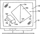
第2Aおよび2B図は、ビデオ・ディスプレー装置52(例えば、テレビ、または、コンピュータのモニタ)のディスプレー画面50の模式図であって、対応するビデオ信号によって電子的に表わされるビデオ画像配列の内の、2個の連続する画像フレーム54a、および、54bを示す。ビデオ信号は、アナログ・ビデオ形式、例えば、NTSC、PAL、および、SECAMを含むビデオ信号形式、および、コンピュータ・ディスプレーで通常用いられる、画素式、または、ディジタル化ビデオ信号形式、例えば、VGA、CGA、および、EGAのビデオ信号形式など、各種ビデオ信号形式の内のいずれで表わされたものであってもよい。できれば、画像フレームに対応するビデオ信号は、ディジタル化信号形式のものであることが好ましい。すなわち、当業者であれば熟知のように、もともとそのようなものとして生成されたものか、アナログ・ビデオ信号形式から変換されたものかのいずれかであることが好ましい。
画像フレーム54aおよび54bは、それぞれ、背景60上に位置する、直方形の固相画像特徴56と、ピラミッド型の画像特徴58とを含む。画像フレーム54aと54bにおける画像特徴56と58は、種々の部分が隠れて示されているように異なる外見を持つ。下記の説明のために、ある画像フレームの中のある画像特徴の特定の形をオブジェクト、または、マスクと言うことにする。従って、直方体固相特徴56は、それぞれの画像フレーム54aと54bにおいて、直方体固相オブジェクト56aおよび56bとして示され、ピラミッド型画像特徴58は、それぞれの画像フレーム54aと54bにおいて、ピラミッド型オブジェクト58aおよび58bとして示される。
ピラミッド型画像特徴58は、画像フレーム54aと54bとにおいて、同じ位置と方向で示されるので、ビデオ配列の中で示された場合「外見的に」不動に見えるものである。直方形固形体56は、フレーム54aと54bにおいて、ピラミッド58に対して、相対的に異なる方向、および、位置に示されるので、ビデオ配列の中で示された場合「外見的に」動き、回転しているように見えるものである。画像特徴58と60のこれらの見かけの動きは、図示的なもので、誇張されている。ビデオ配列の画像フレームは通常、30〜60Hzの範囲にある頻度で表示される。ビデオの動きに対するヒトの感覚は、通常、2個以上のフレームを必要とする。画像フレーム54aと54bとはしたがって、本発明を例示するために、従来からのビデオ配列の模式図を表わす。さらに、本発明は決して単純なビデオ画像、画像特徴、または、配列のみに限定されないこと、逆に、任意の複雑さを持つビデオ画像やビデオ配列に適用可能であることが了解されるであろう。
ビデオ圧縮符号化工程概論
第3A図は、ビデオ圧縮符号化工程64の全体機能ブロック図であり、この工程は、複数の画像フレームを持つビデオ配列において、表示の動きを表わすディジタル化ビデオ信号を圧縮するためのものである。ビデオ情報(すなわち、ビデオ配列や信号)の圧縮は、例えば、インタラクティブないしディジタル・テレビや、マルティメディア・コンピュータ・アプリケーションを含む各種用途におけるディジタル・ビデオ情報の経済的なメモリや転送を可能にする。簡単のために、符号化工程64の機能ブロックに割り当てた参照数字は、その機能ブロックによって生成される結果に関しても互換的に用いることとする。
従来のビデオ圧縮法は、時間的相関、または、フレーム間相関と呼ばれる、連続する画像フレーム間の類似性を利用し、それによって、画像フレームの画素ベースの表現値を、動き表現値に変換するフレーム間圧縮を実行する。さらに、従来のビデオ圧縮法は、空間的相関、または、フレーム内相関と呼ばれる、画像フレーム内部の類似性を利用し、それによって、ある画像フレーム内の動きの表示をさらに圧縮するフレーム内圧縮を実行する。
このような従来のビデオ圧縮法においては、この中には、MPEG-1、MPEG-2、および、H.26Xが含まれるが、時間的・空間的相関は、固定した、規則的な(例えば、方形)画素配列の単純な線形移動に対して決定される。しかしながら、ビデオ情報は通常、画素の正方形配列を線形移動することによっては正確に表わすことのできない任意のビデオの動きを含む。そのため、従来のビデオ圧縮法は通常、無視できない誤差成分を含むこととなり、これが、圧縮比と精度に制限を与える。
逆に、符号化工程64は、オブジェクトベースのビデオ圧縮を利用し、それによって、フレーム間の動き、および、フレーム内画像特徴を符号化する際の精度と融通性とを改善する。符号化工程64は、固定の規則的な画素配列ではなく、任意の形態を持つオブジェクトに対してビデオ情報を圧縮する。これによって、誤差成分は減少するから、圧縮効率と精度は改善される。もうひとつの利点として、オブジェクトベースのビデオ圧縮は、圧縮ビデオ情報を処理する際に有効な、インタラクティブビデオ編集能力をもたらす。
第3A図を参照すると、機能ブロック66は、あるビデオ配列の画像フレームにおけるユーザー定義によるオブジェクトを、同じ画像フレーム内の他のオブジェクトからセグメント化することを示す。オブジェクトは、任意の形態を持っていてよいが、できれば、ディスプレー画像において、個別の画像特徴を表わしていることが好ましい。セグメント化とは、その画像フレームにおける、オブジェクトに対応する画素を特定することを含む。ユーザー定義によるオブジェクトは、ビデオ配列の中の画像フレームのそれぞれにおいて定義される。例えば、第2A、2B図において、直方体オブジェクト56aと56b、および、ピラミッド型オブジェクト58aと58bとは別々にセグメント化される。
セグメントされたオブジェクトは、そのオブジェクトの、2値又は多値ビット(例えば、8ビット)「アルファー・チャンネル」マスクで表わされる。オブジェクトマスクは、あるオブジェクトの、大きさ、形、位置を個別の画素として表わすものである。簡単のために、以下の説明では、2値マスクを取扱うこととする。2値マスクにおいては、オブジェクトの各画素は、通常の24ビット(3個の色成分値のそれぞれに対して8ビットずつ)ではなく、ただ一つの2値ビットで表わされる。多値ビット(例えば8ビット)マスクも従来使用されている。
機能ブロック68は、各オブジェクトの「特徴点」が、ユーザーによって定義されることを示す。特徴点はできれば、オブジェクトの際立った特徴又は態様であることが好ましい。例えば、隅角70a〜70c、および、隅角72a〜72cを、それぞれ直方体56とピラミッド58の特徴点としてユーザーが定義することができる。各画像フレームにおける、各オブジェクトマスクと、その特徴点に対応する画素は、メモリ装置24に含まれるオブジェクトデータベースに保存される。
機能ブロック74は、連続する画像フレームにおける特徴点の位置の変化を特定し、連続する画像フレーム間の特徴点に対して軌跡が求められることを示す。軌跡とは、特徴点の移動の方向及び程度を表わす。機能ブロック76は、直前フレームN-1と現在フレームNとの間におけるオブジェクトの特徴点の軌跡も、オブジェクトデータベースから取り出されることを示す。
機能ブロック78は、直前フレームN-1と現在フレームNの間において、オブジェクトに対して、粗動き変換を求めることを示す。粗動き変換は、フレームN-1とN間における特徴点軌跡に基づいて実行される。粗動き変換は、直前フレームN1と現在フレームNの間におけるオブジェクトの変化の近似を提供する。
機能ブロック80は、現在フレームNにおけるオブジェクトのマスクが、メモリ装置24のオブジェクトデータベースから取り出されることを示す。
機能ブロック90は、量子化マスターオブジェクト(即ち、「スプライト」)が、画像フレーム配列における画像特徴に対応するオブジェクト(即ち、マスク)66と、特徴点軌跡74から形成されることを示す。このマスターオブジェクトは、できれば、複数フレームに表われることになる、オブジェクトの態様又は特徴のすべてを含んでいることが好ましい。例えば、第2A、2B図に関して言えば、フレーム54bの直方体56は、フレーム54aに示されていない側面78bを含む。同様に、直方体56は、フレーム54aにおいて、フレーム54bには示されていない側面78aを含む。直方体56のマスターオブジェクトは、両側面78aと78bとを含む。
粗動き変換78は、フレームN-1とN間におけるオブジェクトの変化を完全に表わさないことがよくある。例えば、直前フレームN-1におけるオブジェクト、例えば、直方体54aは、現在フレームNにおいてオブジェクトのすべての特徴を含んでいないかもしれない。例えば、直方体54bの側面78bのように。
したがって、変換の精度を上げるために、直前フレームN-1と現在フレームNにおけるオブジェクトのマスクの交点を、当業者には既知の論理AND機能を用いて求める。現在フレームNにおけるオブジェクトのマスクを、得られた交点から差し引き、直前フレームN-1のオブジェクトに含まれない、現在フレームNのオブジェクトの部分又は特徴(例えば、前述の直方体54bの側面78b)を特定する。オブジェクトの新たに特定された部分を、マスターオブジェクト90に取り込み、それによって、マスターオブジェクトが、フレームN-1とNにおいて、オブジェクトの完全な表現値を含めることができるようにする。
機能ブロック96は、直前フレームN-1におけるオブジェクト98の量子化形態(例えば、画像フレーム54aにおける直方体56a)が、密な動き変換によって変換され、それによって、現在フレームNにおけるオブジェクト102の予測形(例えば、画像フレーム54bにおける直方体56b)を与えることを示す。この変換は、オブジェクトベースのフレーム間圧縮を与える。
密な動き変換は、できれば、フレームN-1の量子化した直前フレームのオブジェクト98と現在フレームNのオブジェクトとの間のアフィン変換を求め、かつ、そのアフィン変換を、量子化した直前フレームのオブジェクト98に適用することから成ることが好ましい。好ましいアフィン変換は、アフィン変換係数104によって表わされ、かつ、線形移動、回転、拡大、および、斜行を記述することができる。アフィン変換は、密な動き推定から求められるが、できれば、直前量子化オブジェクト98と、現在フレームNのオブジェクトとの間において、画素単位のマッピングを含むことが好ましい。
予測した現在オブジェクト102は、密な動き変換96によって修正された量子化した直前フレームのオブジェクト98によって表わされるが、これは、比較的複雑な動きを表わすことができるだけでなく、マスターオブジェクト90から得られるどのような新しい画像局面をも表わすことができる。このようなオブジェクトベースの表現は、比較的精度が高い。というのは、オブジェクトに関連付けられる知覚的・空間的な連続性が、異なる画像フレームにおける異なるオブジェクト間に通常見られる関係変化から生ずる誤差を除去するからである。さらに、オブジェクトベースの表現の場合、ユーザーは、異なるオブジェクトを、異なる解像度レベルで表わすことが可能であるから、それによって、様々の複雑さを持つ、複数のオブジェクトを表わす際に関わる効率と精度を最適化することができる。
機能ブロック106は、画像フレームNに関して、予測した現在オブジェクト102を、現在フレームNのもともとのオブジェクト108から差し引き、それによって、予測オブジェクト102における推定誤差110を求めることを示す。推定誤差110は、量子化した直前フレームのオブジェクト98に対する、画像フレームNにおける現在オブジェクト108の圧縮表現である。もっと具体的に言うと、現在オブジェクト108は、推定誤差110と量子化した直前フレームのオブジェクト98とから復号化、すなわち、再構成することができる。
機能ブロック112は、推定誤差110が、従来の「損失性」(ロス−損失を伴う)静止画像圧縮法、例えば、格子によるサブバンド圧縮や、その他のウェーブレット圧縮法、または、符号化法によって、または、離散コサイン変換(DCT)符号化法によって圧縮、すなわち、符号化されることを示す。これら圧縮法については、前者は、バイジャナタン(Vaidyanathan)著「マルチレート装置、および、フィルタ・バンク(Multirate Systems and Filter Banks)」(PTR Prentice-Hall, Inc., Englewood Cliffs,ニュージャージー州、アメリカ、1993)に、後者は、ペンベーカーら(Pennebaker et al.)著「JPEG−静止画像圧縮基準」(Van Nostrand Reinhold,ニューヨーク、1993)に記載の通りである。
当業者には既知のように、「損失性」圧縮法は、データ圧縮を増そうとすると、データ歪を生ずる。データ歪とは、圧縮前の元データと、圧縮し、展開した後に得られるデータとの間の変異を指す。下記の例示のために、機能ブロック102の圧縮、すなわち、符号化は、ウェーブレット符号化法であると想定する。
機能ブロック114は、機能ブロック112によって得られるウェーブレット符号化の推定誤差が、従来の「ロスレス」静止画像圧縮法によってさらに圧縮、即ち「符号化」され、それによって圧縮データ116を形成することを示す。好ましい通例の「ロスレス」静止画像圧縮法としては、ペンベーカーら(Pennebaker et al.)著「JPEG−静止画像圧縮基準」に記載のエントロピー符号化法がよい。当業者には既知のように、「ロスレス」圧縮法はデータ歪を誘発しない。
誤差フィードバック・ループ118は、フレームNのオブジェクトについて機能ブロック112で得られたウェーブレット符号化推定誤差を利用して、直後フレームN+1に対する直前量子化オブジェクトを得る。フィードバック・ループの第1手順として、機能ブロック120は、機能ブロック112で得られたウェーブレット符号化推定誤差が逆ウェーブレット符号化、即ちウェーブレット復号化され、それによって画像フレームNのオブジェクトにたいする量子化誤差122を形成することを示す。
「損失性」静止画像圧縮法によって、推定誤差110を連続的に符号化し、復号化することの効果は、量子化誤差122から、一般に視認者には知覚されないビデオ情報を取り除くことにある。このため、そのような高い周波数成分を取り除くことによって、画像品質をほとんど損なわずに、最大約200%の画像圧縮率を得ることができる。
機能ブロック124は、画像フレームNに対して、量子化誤差122と予測オブジェクト102の双方が加算され、それによって、画像フレームNに対する量子化オブジェクト126を形成することを示す。タイミング調整遅延128の後、量子化オブジェクト126は、量子化した直前フレームのオブジェクト98となり、画像フレームN+1の対応するオブジェクトを処理する基礎として用いられる。
符号化工程64は、連続する画像フレームにおける対応するオブジェクトの時間的相関を用いて、改善されたフレーム間圧縮を獲得し、さらに、オブジェクト内の空間的相関を用いて、高精度の、効率的なフレーム内圧縮を獲得する。フレーム間圧縮に関して言えば、動き推定と補償を実行し、それによって、あるフレームにおいて定義されたオブジェクトを、直後のフレームにおいて推定する。直後フレームにおけるオブジェクトの動きベースの推定は、従来のブロックベースのオブジェクト表現よりもはるかに少ない情報しか必要としない。フレーム内圧縮に関して言えば、各オブジェクトに対する推定誤差信号を圧縮して、それによって、あるフレーム内の、そのオブジェクトの空間的相関を利用することができ、また、異なるオブジェクトを、異なる解像度で表わすことができる。フィードバック・ループ118によって、連続するフレームにおけるオブジェクトを、完全に展開されたオブジェクトから予測することができるから、そのため推定誤差の累積を防止することができる。
符号化工程64は、出力として、複数画像フレームのビデオ配列における表示の動きを表わす量子化ビデオ信号の圧縮表現、即ち符号化表現を提供する。この圧縮表現、即ち符号化表現は、オブジェクトマスク66、特徴点68、アフィン変換係数104、および、圧縮誤差データ116を含む。この符号化表現は、ビデオ情報の使用される特定の用途に従って、保存されてもよいし、転送されてもよい。
第3B図は、マスターオブジェクト90を符号化、即ち圧縮するためのマスターオブジェクト符号化工程130の機能ブロック図である。機能ブロック132は、マスターオブジェクト90が、従来の「損失性」静止画像圧縮法、例えば、格子によるサブバンド圧縮法ないし他のウェーブレット圧縮法、または、離散コサイン変換(DCT)符号化法によって圧縮、または、符号化されることを示す。できれば、機能ブロック132は、ウェーブレット符号化法を採用することが好ましい。
機能ブロック134は、機能ブロック132によって得られたウェーブレット符号化のマスターオブジェクトがさらに従来の「ロスレス」静止画像圧縮法によって圧縮、即ち符号化され、圧縮マスターオブジェクトデータ136を形成することを示す。好ましい通例のロスレス静止画像圧縮法はエントロピー符号化法である。
符号化工程130は、出力として、圧縮マスターオブジェクト136を提供する。符号化工程64によって与えられる圧縮表現、即ち符号化表現と共に、圧縮マスターオブジェクト136は、保存ないし転送後に展開、即ち復号化し、複数画像フレームのビデオ配列を生成させてもよい。
符号化工程64を、ある画像フレーム内部における単一オブジェクトに対応するビデオ情報を符号化することに関連して説明する。第2A図、2B図に示したように、また、上述のように、符号化工程64は、ある画像フレームにおける個々のオブジェクトごとに(例えば、第2A図、2B図のオブジェクト56と58)別々に実行される。さらに、多くのビデオ画像は、その上に任意の数の画像特徴又はオブジェクトをレンダリングする背景を含む。できれば、背景は、すべてのユーザー指定によるオブジェクトを処理した後、本発明によるオブジェクトとして処理されることが好ましい。
画像フレーム内のオブジェクトの処理のためには、それらオブジェクトが個別に特定されることが必要である。できれば、符号化工程64は、ある画像フレームについて、最前面のオブジェクト(単数または複数)から始まって、順々に進行していき最後尾のオブジェクト(例えば、背景)に至るオブジェクトに適用することが好ましい。符号化オブジェクトのビデオ画像への構成は、できれば、最後尾のオブジェクト(例えば、背景)から始まって、順々に最前面のオブジェクト(例えば、第2A、2B図の直方体56)に向かって進行することが好ましい。符号化オブジェクトのレイヤ化は、ある画像フレームのオブジェクトと関連する個別のレイヤ化データとして通信してもよいし、別法として、レイヤ化又は圧縮化シーケンスに対応する、あるシーケンスの中の符号化オブジェクトを転送、または、獲得することによって通信してもよい。
オブジェクトセグメントと追跡
一つの好ましい実施態様においては、機能ブロック66において参照される画像フレーム内の画像のオブジェクトをセグメント化することによって、ユーザーはインタラクティブなセグメント化を得ることができる。本発明のオブジェクトのセグメントは、オブジェクトをセグメント化するに当たって高精度を可能にし、比較的速く、かつ、セグメントされるオブジェクトを定義するにあたって、ユーザーに最適の柔軟性を提供する。
第4図は、オブジェクトのセグメント工程140の機能ブロック図であり、この工程によって、あるビデオ配列のある画像フレームの選ばれたオブジェクトをセグメント化する。工程140によるオブジェクトのセグメントは、高精度で速く、ユーザーにとって定義の簡単な、オブジェクトの感覚的グループ化を実現させる。
第5A図は、画像フレーム54aと直方体オブジェクト56aを示すビデオ・ディスプレー装置52のディスプレー画面50の模式図である。ディスプレー画面50へのレンダリング時、直方体オブジェクト56aはオブジェクト辺縁(perimeter)142(図では、はっきりと分かるようにオブジェクト56aから離して描かれる)を含む。このものは、オブジェクト内部144の境界となる。オブジェクト内部144とは、ディスプレー画面50におけるオブジェクト56aの輪郭を指し、一般に、内部表面、または、図示のように、画像特徴の外表面に一致する。下記の説明は、特に、直方体オブジェクト56aに関してなされるものであるが、ある画像フレームにおいてセグメントされる各オブジェクトに同様に適用可能である。
機能ブロック146は、ユーザーが、オブジェクト内部144内に、オブジェクト辺縁142の内部輪郭148を形成することを示す。ユーザーはできれば内部輪郭148を、マウスや、追跡ボールのような通例のポインター、または、カーソル制御装置で形成することが好ましい。内部輪郭148は、オブジェクト辺縁142から指定の距離150以内に形成される。指定距離150は、ユーザーによって選ばれるが、その大きさは十分大きく、ユーザーは、内部輪郭148を、辺縁142の指定距離150以内に、比較的速やかに形成することができる。指定距離150は、例えば、約4〜10画素に相当する。
機能ブロック146は、ビデオ配列の中のキー・フレームに関連して実行される。例えば、従来の活動映画の場面に関して言えば、キー・フレームとは、ある場面の複数のフレームのうちの第1フレームである可能性が多い。この機能にユーザーを参加させることによって、オブジェクトセグメント工程140は半ば自動化されるが、それでいて、オブジェクトのセグメントされる精度と柔軟性は目立って増す。キー・フレームを除いては、その後の画像フレームにおけるオブジェクトは、以下にさらに詳細に述べるように自動的にセグメント化される。
機能ブロック152は、内部輪郭148が自動的に拡大され、外部輪郭156を形成することを示す。外部輪郭156の形成は、外部輪郭156が、内部輪郭148からユーザー定義数の画素だけ増えるように、輪郭148の比較的簡単な画像拡大として実行される。できれば、内部輪郭148と外部輪郭156との間の距離はおよそ距離150の2倍となることが好ましい。
機能ブロック158は、内部輪郭148と外部輪郭156の間の画素が、それらがオブジェクト内部144の中にあるかどうかに関する、あらかじめ定義された属性に従って分類され、それによって、第3A図に関連して記載された型のオブジェクト辺縁142と、対応マスク80を自動的に特定することを示す。できれば、画像属性は、画素・カラーと位置を含むことが好ましく、かつ、いずれの属性も、それだけで、または、他の属性と併せて使用できるものであることが好ましい。
この好ましい実施態様では、内部輪郭148と外部輪郭156における画素の各々が、(r、g、b、x、y)の形の5次元ベクトルで表わされる「クラスター中心」を定義する。用語r、g、およびbは、画素の各々に関連する赤、緑、および、青のカラー成分に対応し、用語x、および、yは、画素の位置に対応する。内部輪郭148の中の画素に対応するm個のクラスター中心ベクトルは、{I0,I1,...,Im-1}で表わされ、外部輪郭156の中のn個のクラスター中心ベクトルは、{O0,O1,...,On-1}で表わされる。
クラスター中心ベクトルIiとOjの間の画素は、5次元ベクトル空間において、各画素のもっとも近いベクトルを特定することによって分類される。各画素について、それぞれのクラスター中心ベクトルIiおよびOjの各々にたいする絶対距離diおよびdjは、下記の式によって計算される。

機能ブロック162は、ユーザーが、先頭フレームまたはキー・フレームの各オブジェクトにおいて、少なくとも2個の、できればそれよりたくさんの(例えば4から6個の)特徴点を選択することを示す。できれば、特徴点は、オブジェクトの比較的際立った局面であることが好ましい。例えば、直方体画像特徴56に関連して言えば、隅角70a〜70cを特徴点として選ぶことも可能である。
機能ブロック164は、各選ばれた特徴点(例えば、隅角70a〜70c)を取り囲む複数の画素から成るブロック166が定義され、後続画像フレーム(例えば、直後画像フレーム)の対応するブロックにマッチングされることを示す。画素ブロック166は、ユーザー定義によるものではあるが、できれば、画像内部144内の画素だけを含む32x32画素配列を含むものであることが好ましい。機能ブロック158で決められることであるが、(例えば、隅角70bと70c)画素ブロック166の内、オブジェクト内部144の外にはみ出す画素168(斜線で示す)は除外される。画素ブロック166は、従来のブロックマッチング工程、または、下記にさらに詳細に述べるポリゴンマッチング工程によって特定される最小絶対誤差によって、直後画像フレームの対応する画素ブロックにマッチングされる。機能ブロック170は、あるオブジェクトの粗動き変換が、2個の連続する画像フレームにおける対応する特徴点から求められることを示す。機能ブロック172は、現在画像フレームのマスク80が粗動き変換によって変換され、それによって、直後画像フレームのマスク80に対する推定の得られることを示す。後続画像フレームの中に特定されない、現在フレーム中の特徴点はいかなるものも無視される。
機能ブロック174は、直後画像フレームにおけるマスク80に関して得られた推定がフレーム1個分遅らせられ、かつ、その直後サイクルに対して輪郭176として機能することを示す。同様に、機能ブロック178は、対応する特徴点もフレーム1個分遅らせられ、同じ直後のフレームに対して初期特徴点180として利用されることを示す。
ポリゴン・マッチング
ポリゴン・マッチング200の機能ブロック図であり、この方法は、連続する画像フレームにおける、各対応画素のペアについて動きベクトルを求めるものである。このような密な動きベクトル計算は、第3A図の密な動き変換96を求める基礎となる。
ポリゴン・マッチング工程200は、従来のブロック・マッチング工程同様、連続する画像フレーム間の広範な動きを求めることができる。しかも、従来のブロックマッチング工程と違って、ポリゴンマッチング工程200は、オブジェクト辺縁近傍、または、直上に位置する画素に対する高精度を維持するから、その生成する誤差は目立って少ない。ポリゴン法200の好ましい実施態様においては、計算効率が向上する。
ポリゴンブロック法200を、第7A、および、7B図を参照しながら説明する。この図は、2個の連続する画像フレーム202a、202bを示すディスプレー画面504の模式図であり、それら画像フレームにおいて、画像特徴204が、それぞれ、オブジェクト204a、および、204bとしてレンダリングされる。
機能ブロック206は、画像フレーム202aと202bにおけるオブジェクト204aと204bとが特定され、例えば、オブジェクトセグメント法140によってセグメントされることを示す。
機能ブロック208は、オブジェクト204bに対して適用される画素ブロック210b(例えば、15x15画素)と、オブジェクト204aの周囲の探索領域212に対する次元数が求められることを示す。画素ブロック210bは、それに対して、オブジェクト204aにおける対応画素ブロック210aが特定される、そのような、オブジェクト204bの周囲の領域を定義する。探索領域212は、対応画素ブロック210aが求められる領域を定める。できれば、画素ブロック210bと探索領域212とは、直角の規則的な画素配列であって、ユーザーによって定義される大きさを持つものであることが好ましい。
機能ブロック214は、オブジェクト204b内の初期画素216が特定され、現在画素と指定されたことを示す。初期画素216は、各種の基準の内のいずれで定義されてもよい。そのような基準としては、例えば、垂直最大延長位置の画素、および、水平最小延長を持つ画素などがある。図示の座標軸220に従って配置された、ディスプレー画面50上の画素に関して言えば、初期画素216は、最大y座標値と、最小x座標値を持つ、オブジェクト214bの画素として表わしてもよい。
機能ブロック222は、画素ブロック210bが、現在画素を中心とし、その周辺に広がっていることを示す。
機能ブロック224は、画素ブロック210bが、オブジェクト204bに含まれない画素(例えば、第7B図の斜線で示した画素226)を含むかどうか関する調査を表わす。この調査は、機能ブロック206によって特定されたオブジェクトを参照して実行される。現在画素に位置づけられる画素ブロック210b内の画素がオブジェクト204b外にはみ出した場合は必ず、機能ブロック224は、機能ブロック228に進み、その他の場合は機能ブロック232に進む。
機能ブロック228は、画素ブロック210bのうち、オブジェクト204bの外にはみだす画素(例えば、画素226)は、画素ブロック210bによって定義される領域から除外し、それによって、画素ブロック210bが、オブジェクト204b内部の画素だけを含むようにする。その結果、画素ブロック210bは、もともと定義された正方形、ないし、長方形領域よりもさらに複雑なポリゴンとなる。
機能ブロック232は、オブジェクト204aの中のある画素が、オブジェクト204bにおける現在画素と対応すると特定されたことを示す。オブジェクト204aにおけるその画素を、直前対応画素と言う。できれば、直前対応画素は、探索領域212の各画素の周囲に画素ブロック210aを形成し、かつ、画素ブロック210aと、オブジェクト204bにおける現在画素の周囲の画素ブロック210bの間の相関を求めることによって特定することが好ましい。画素ブロック210aと210bの間の各相関は、例えば、絶対誤差によって求めてもよい。直前対応画素は、探索領域212の中に、画素ブロック210bにたいする絶対誤差が最小となる画素ブロック210aを特定することによって特定される。画素ブロック210bに対する画素ブロック210aの合計絶対誤差は、次のようにして求めることができる。
上に規定したように、絶対誤差Eの総計は、m x nの画素次元を持つ画素配列を持つ画素ブロックを含む。ポリゴンを持つ画素ブロック210bは、ポリゴン画素ブロック210bの外にはみ出すすべての画素のカラー成分に対してゼロ値を定義することによって、比較的簡単に取り込むことができる。
機能ブロック234は、オブジェクト204b内の各画素と、オブジェクト204a内の対応直前画素間の動きベクトルMVが求められることを示す。動きベクトルは、オブジェクト204bの画素の位置と、オブジェクト204aの対応直前画素の位置の間の差と定義される。
MV=(xi-xk’,yj-yl’)
ここに項xiとyiは、それぞれ、画素ブロック210bにおける画素の、x-座標位置、および、y-座標位置に一致し、項xk’とxl’は、それぞれ、画素ブロック210aの対応直前画素のx-座標位置、y-座標位置に一致する。
機能ブロック236は、オブジェクト204bが、何らかの残存画素を含むかどうかに関する調査を表わす。オブジェクト204bが残存画素を含む場合は必ず、機能ブロック236は、機能ブロック238に進み、そうでなければ終了のブロック240に進む。
機能ブロック238は、オブジェクト204bの次の画素が、あらかじめ指定された方式、または、配列によって特定されることを示す。初期画素は、機能ブロック214に関連して前述のように選ばれたが、後続画素は、ある列において(すなわち、共通のy-座標軸の)、まずすぐ次の画素を特定することによって定義し、かつ、もしもオブジェクト204が列の中に他に画素を含んでいなければ、1段下の列の、第1、すなわち、最左画素(すなわち、最小x-座標値を持つ)に進んでもよい。このようにして特定された画素は、現在画素に指定され、機能ブロック238は、機能ブロック222に戻る。
ポリゴンブロック法200は、対応画素が、仮に、オブジェクトの辺縁上に、または、辺縁近傍に位置していても、対応画素を正確に特定する。従来のブロック・マッチング工程に見られたかなりの誤差の原因は、画素ブロック210bの内、オブジェクト204bの外にはみ出した画素を除外ないし無視することによって除去される。従来のブロック・マッチング工程は、均一なブロック形には厳密に適用されるが、セグメントオブジェクトに対しては厳密には適用されない。均一ブロック形態は、オブジェクトの辺縁近傍の画素に対しては重大な誤差を引き起こす。なぜなら、オブジェクトの外にはみ出す画素は、オブジェクトが動くにつれ、または、その背景が変化するにつれ、かなりの変化を受けるからである。従来のブロック・マッチング工程においてはそのようにはみ出し画素の変動が含まれるのであるから、オブジェクト辺縁近傍の画素は、厳密には、直前画像フレームの対応画素と相関されない。
オブジェクト204bの各画素に関しては、オブジェクト204aの対応直前画素が特定される。これは、直前オブジェクト204aの画素の各々について、画素ブロック210bと、画素ブロック210aとを比較することによって実行される。直前対応画素とは、オブジェクト204aにおいて、画素ブロック210bともっとも高い相関を持つ画素ブロック210Aを持つ画素である。従来のやり方で処理するならば、この解決には、各直前対応画素を特定するために実質的な計算が要求される。具体例を挙げるならば、m x n画素の次元を持つ探索領域212よりもはるかに小さいn x n画素の次元を持つ画素ブロックについて、直前オブジェクト204aにおける各直前対応画素を特定するために、約n2 x m2個の計算が必要である。
画素ブロック相関工程
第8図は、修正画素ブロック相関工程260の機能ブロック図であり、できれば、これを、機能ブロック232に関連して記載したものの代わりとして用いることが好ましい。修正相関工程260は、画素ブロック210bと210aを相関する際に内在的に認められる冗長度を利用し、それによって、必要計算数を際立って減少させる。
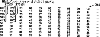
相関工程を、第9A〜9G、および、10A〜10Gを参照しながら説明する。これらの図は、連続する画像フレーム202aと202bに対応する任意の画素群を模式的に表わす。特に、第9A図は、5x5画素の次元を持つ画素ブロックの模式図であり、この図において、各文字は、個別の画素に相当する。画素ブロック262の画素は、個別の行264を含む、画素の直角規則配列として配置される。第9B図は、q x qの次元を持ち、直前画像フレーム202aの探索領域212に対応する画素配列266を表わす。第9B図の各々の数字は個別の画素を表わす。従来の直角規則画素ブロック262と関連して説明するけれども、相関工程260は、ポリゴン・マッチング工程200に関連して説明した型のポリゴン画素ブロックにも同様に適用できる。
機能ブロック268は、初期画素ブロック(例えば、画素ブロック262)が、中央画素Mに関して定義され、探索領域212(例えば、画素配列266)を亘って走査されることを示す。この走査は、一般に、従来のブロック・マッチング工程に見られるように、ラスター・パターン(一部第7A図に示す)の形で実行される。第9C〜9Gは、画素ブロック262と画素配列266の間のブロック・マッチング工程におけるおよそq2個の手順の内の5個を模式的に図示する。
画素ブロック262の、画素配列266にたいする横断走査は、従来のやり方で行なわれるけれども、両者の間の相関に関する計算は、本発明にしたがって、別様のやり方で実行される。特に、相関(例えば、絶対誤差)は、各走査位置において、画素ブロック262の各行264に対して求められ、される。各走査位置において、画素ブロック262の各行264について求められ、保存された相関は、行相関270と呼ばれる。そのうちのいくつかを、相関された画素に関連させることによって、第9C〜9G図に記号で示す。具体的に示すと、第9C図は、行相関270(1)を示すが、これは、画素配列266に揃えられた、画素ブロック262の単一行264に対して求められたものである。同様に、第9D図は、行相関270(2)と270(3)とを示し、これらは、画素配列266に揃えられた画素ブロックの2個の行264に対して求められたものである。第9E〜9G図は、画素配列266にたいする、上記に続く3個の連続走査位置における、画素ブロック262との、同様の行相関を示す。
画素配列266上を、初期画素ブロック262を走査することによって、行相関のメモリ配列、または、データベースが得られる。画素ブロック262が、r数の行264を持ち、かつ、画素配列266がq x q個の画素を持つ場合、行相関データベースは、約rq2個の行相関を含む。この行相関の数はほんの近似値である。なぜなら画素ブロック262は、できれば最初に画素配列266の上を、画素Mが画素配列266の画素の内の第1列に揃うように、走査されることが好ましいからである。
第9C図に示されるものから始まる残余の手順は、画素配列266の上を画素ブロック262が完全に2回に亘って走査した後に行われる(すなわち、画素配列266の第1列、第2列に画素Mが揃った後)。
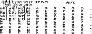
機能ブロック274は、次の画素ブロック(第10A図)が、例えば、画像フレーム202bにおいて、画素Mと同じ列の中心画素Nに関して定義されることを示す。画素ブロック276は、画素ブロック262に含まれない画素行278と、画素ブロック262に含まれる画素行280とを含む。画素ブロック276は、画素ブロック262に含まれる行282(第9A図)を含まない。次の画素ブロック276におけるこのような増加させる定義のやり方は、実質的に、従来のブロック・マッチング工程に用いられるものと同じである。
機能ブロック284は、画素ブロック276が、機能ブロック268に関連して前述したようなやり方で画素配列266の上を亘って走査されることを示す。第9C〜9G図と同様に、第10B〜10G図も、画素ブロック276が、画素配列266の上を走査される様を示す。
機能ブロック286は、行278について、各走査位置において、行相関が求められ、保存されることを示す。従って、行相関288(1)〜288(5)は、それぞれ、第10B〜10Fに示す行278の走査位置に関連して求められる。
機能ブロック290は、画素ブロック276の行280の各々について、メモリ行計算値が、以前に計算された各走査位置に関して取り出され、機能ブロック268に保存されることを示す。例えば、第9C図の行相関270(1)は、第10C図の270’(1)と同じである。同様に、第10D〜10F図の行相関270’(2),270’(3),270’(5)〜270’(8)および270’(15)〜270’(18)は、第9D、9E、および、9Gの対応する行相関と同じである。従って、画素ブロック276について、ただ行相関288のみが各走査位置について計算される。この結果、画素ブロック276に必要な計算の数は、ほぼ80%減少される。
機能ブロック292は、後続画素ブロック294(第11A図)が、画素Mに関して次に続く列の中心画素Rに関して定義されることを示す。画素ブロック294は、第9A図の画素ブロック262の行264と類似ではあるが、はっきりと異なる画素から成る行296を含む。特に、行296は、行264には含まれない画素A’〜E’を含む。後続画素ブロック294のこのような増加させる定義のやり方は、実質的に従来のブロック・マッチング工程に用いられるものと同じである。
機能ブロック298は、画素ブロック294が、機能ブロック268、および、276に関連して前述したやり方で、画素配列266(第9B図)の上を亘って走査される。第11B〜11F図は、画素ブロック294を、画素配列266上を走査する様を表わす。
機能ブロック300は、行296の各々について、行相関が求められ、保存されることを示す。したがって、行相関302(1)〜302(18)は、第11B〜11Fに示した行296の走査位置に関連して求められる。
行相関302(1)〜302(18)の各々は、画素ブロック262(第9A図)に関して実行された行相関に関連して、短縮したやり方に基づいて計算してもよい。
例えば、第11D図の行相関302(1)〜302(18)は、第9E図の副行相関304(4)〜304(8)と同じ副行相関304’(4)〜304’(8)を含む。したがって、行相関302(4)〜302(8)は、それぞれの行相関270(4)〜270(8)から、画素01A、02B、03C、04D、および、05Eに対する後者の相関値を差し引き、それによって、それぞれ、副行相関304(4)〜304(8)を形成してもよい。行相関302(4)〜302(8)は画素のペア56A’、57B’、58C’、59D’、および、50E’に対する相関値を、それぞれの副行相関値304(4)〜304(8)に加えて得てもよい。
それぞれの形相間270(4)〜270(8)から、行相関302(4)〜302(8)を求めるには、画素ブロック294には含まれない、画素ブロック262の画素A〜E列に対応する、個々の画素相関値を差し引き、かつ、画素ブロック294には含まれるが、画素ブロック262には含まれない画素A’〜E’列に対する画素相関値を足し加える必要がある。この方法は、行相関302(4)〜302(8)の各々に対し、従来のやり方であれば、各行相関を求めるのに5回の加算が必要とされるのに対し、1回の引き算、1回の足し算で代用する。さらに大きな次元の画素ブロックが好まれれば好まれる程、従来の計算法に優るこの方法の利点がますます際立つ。従来の画素マッチング工程は、画素配列266にたいする初期画素ブロック262の各走査位置について、総合ブロック相関のみを特定するだけである。そのため、全画素にたいする全相関値を、各走査位置について個別に計算しなければならない。逆に、相関工程260は、メモリ行相関270を利用し、それによって、必要な計算数を目立って減少させる。相関工程260によってもたらされる速度と、プロセッサーのリソース要求度における改善は、行相関を保存するために必要とされる装置条件を補って余りある。
相関工程260は、第9〜11図を参照しながら記載してきたが、これは、本発明の特徴を例示するためのものであることが了解されるであろう。例示し示したように、本発明は、コンピュータ装置で実行するのに特に相応しい繰り返し、または、周期的性質を含む。この繰り返し、または、周期的性質は、画素ブロックと画素配列に依存するものであるが、当業者であれば、十分に理解し、導入可能なものである。
多次元変換
第12図は、第1と第2の連続する画像フレーム間において多次元変換を生成し、かつ、転送ないし保存のためにマッピングを量子化することから成る、変換法350の機能ブロック図である。この多次元変換は、できれば第3図の機能ブロック96と関連させて使用するのが好ましい。変換法350は、第7A図と第13図に基づいて説明される。これらの図の内の後者は、第7B図と同様、ディスプレー画面50の模式図であって、画像特徴204がオブジェクト204bとしてレンダリングされる画像フレーム202bを示す。
変換法350は、できれば、線形移動、回転、拡大、および、斜行の内のいずれか、または、その全てを含む複雑な動きを表わすことのできる多次元アフィン変換を実行するものであることが好ましい。変換法350は、1次元のみで、かつ、線形移動にしか関わらない従来のビデオ圧縮法、例えば、MPEG-1、MPEG-2、および、H.26Xよりもはるかに優る。この点において、変換の次元性とは、後で詳しく述べるように、変換の一般形における座標の数を指す。複雑な動きを、本発明に従って表現することによって精度は増すけれども、それによる誤差は、従来の表現法によるものよりも少ない。従って、圧縮効率が増す。
機能ブロック352は、オブジェクト204aおよび204bの画素の密な動き推定を求めることを示す。できれば、密な動き推定は、ポリゴン・マッチング工程200で入手することが好ましい。前述したように、密な動き推定は、座標(xi,yj)における、画像フレーム202bのオブジェクト204bの画素と、座標(xi’,yj’)における、画像フレーム202aのオブジェクト204aの画素との間の動きベクトルを含む。
機能ブロック354は、変換ブロック356の配列が、オブジェクト204bを見込むように定義されることを示す。できれば、変換ブロック356は、例えば、32x32画素の次元を持つ、画素の直角規則配列であることが好ましい。
機能ブロック358は、各変換ブロック356に対して一つの多次元アフィン変換が生成されることを示す。できれば、アフィン変換は、1次であって、次のように表わされるものであることが好ましい。すなわち、
xi’=axi+byi+c
yi’=dxi+eyi+f
かつ、動きベクトルがそれに対して比較的高い信頼度を持つすべての画素について求めることが好ましい。このアフィン変換は、xiとyiとが、二つの座標xiとyiに関して定義されるという点で2次元を持つ。
動きベクトルの相対的な信頼度とは、対応する画素間の動きベクトルが、他の画素に対して、一意的に決定される、その精度を指す。例えば、比較的大きな画素配列の中にあり、かつ、均一な色を持つ(例えば、黒)、特定の画素間の動きベクトルは、通常、高精度に求めることはできない。特に、第1画像フレームにおける黒画素について言えば、後続画像フレームの画素配列の中の多数の画素が同一相関を持つ(すなわち、画素ブロック間の絶対値誤差)。
逆に、構成画素が、個別的な特徴に対応する画素配列は、後続の画像フレームにおいて、特定の対応画素に対して比較的高い相関を持つ。
比較的高い相関は、特定の画素に対して、極小絶対誤差計算として表わされることが好ましい。従って、比較的信頼度の高い動きベクトルは、このように一意的に低い誤差値に対して求めることができる。例えば、信頼度の高い動きベクトルとは次のようなものとして定義される。すなわち、その動きベクトルに対する最小絶対値誤差が、その画素に関連する次に大きい誤差値よりも、閾値差分を上回る差分少ないもの、である。別法として、信頼度の高い動きベクトルは、相関係数を求める基礎となる絶対誤差値の2次微分に関して定義することもできる。ある特定の値を上回る2次微分は、特定の対応画素間に比較的高い相関のあることを示す。
このような高信頼度の動きベクトルを含むn個の画素が与えられた時、好ましいアフィン変換方程式は、画像フレーム202aと202bにおけるn個の対応画素に関して求められる。画像フレームは、好ましいアフィン変換方程式の、6個の未知係数a、b、c、d、e、および、fを求めるには、画像フレーム202aと202bに、高信頼度の動きベクトルを含む少なくとも3個の対応画素を含んでいなければならない。好ましい次元に関して言えば、変換ブロック356の各々が210個の画素を含み、その内の相当数が通常比較的高い信頼度の動きベクトルを持っていなければならない。これによって得られるn個の方程式は、以下の直線代数式で表わされる。
上述のように、この好ましい二次元アフィン変換方程式は、連続する画像フレーム202aと202b間において、変換ブロック356の線形移動、回転、拡大、および、斜行を表わすことができる。逆に、従来の圧縮標準として用いられる通例の動き変換法は、下記の形の、簡単な変換方程式を用いる。
xi=xi+g
yi’=yi+h
従来の単純化された変換方程式は、動きを、たった二つの係数gとhで表わす。これは、好ましい多次元変換方程式によって得られる情報量(すなわち係数)の僅か3分の1にすぎない。従来の圧縮法と比べて、変換法350によって得られる情報の優れた圧縮効果を現実のものとするには、変換ブロック356の次元を、できれば、MPEG-1やMPEG-2圧縮法によって採用されている16x16の3倍を越えるものとすることが好ましい。変換ブロック356の好ましい32x32画素次元は、従来の変換法の変換ブロックで採用される画素数の4倍に渡る。変換ブロック356の従来に優る大きな次元数は、アフィン変換係数が変換ブロック356の動きを表わす際の高精度とあいまって、変換法350が、従来の圧縮法に優る大きな圧縮を実行するのを可能にする。
本発明によって生成されるアフィン係数は、通常、非整数の、浮動少数点値であって、十分に圧縮しようとすると必ずその精度に悪影響を与えるものであることが了解されるであろう。従って、アフィン変換係数を保存ないし転送する際に要求される帯域を減らすためには、それら係数を量子化することが好ましい。
機能ブロック362は、機能ブロック358に関連して生成されたアフィン変換係数が量子化され、それによって、それら係数を保存ないし転送する際に必要とされる帯域を減少させることを示す。第14図は、変換ブロック356の断片的に拡大表現したものであって、3個の選ばれた画素364a、364b、および、364cを示す。すなわち、これらの画素から、6個の好ましいアフィン変換係数a〜fが求められる。
画素364a〜364cは、それぞれ、それぞれ(x1、y1)、(x2、y2)、(x3y3)の画素座標として表わされる。機能ブロック352の密な動き推定に基づき、画素364a〜364cは、直前画像フレーム202aにおいて、それぞれの対応画素(x1’,y1’),(x2’,y2’),(x3’,y3’)を持つ。従来のやり方と同様に、画素位置(xi,yi)は、整数で表わされ、アフィン変換方程式の解答となる。そして、それに基づき、好ましいアフィン変換係数が求められる。従って、選ばれた画素364a〜364cは、直前画像フレーム202aの対応画素を計算するのに用いられるが、この画素は、通常、浮動小数点値となる。
これらの浮動小数点値の量子化は、対応する画素間の差(xi−xi’,yi−yi’)を、整数形に変換することによって実行する。アフィン変換係数は、まず、差ベクトルと画素値(xi,yi)から画素値(x’i,y’i)を計算し、次に、画素値(x’i,y’i)に関して機能ブロック358の多次元変換方程式を解くことによって求められる。
第14図に示したように、画素364a〜364cは、できれば、変換ブロック356内部の局所的変動にたいする量子化の感度を最小にするように、変換ブロック356内のあちこちに分布される。できれば、画素364aは変換ブロック356の中心か、中心近傍に、画素364bと364cとは上隅に位置するのが好ましい。また、好ましい実施態様においては、オブジェクト204bの変換ブロック356の各々における選ばれた画素が、同じ位置を持つことが好ましい。それによって量子化工程が効率的に実施できるからである。
機能ブロック362の量子化法のもう一つの態様は、異なるレベルの量子化を用いて、様々の動きの程度を表わすことができる、ということである。その結果、比較的単純な動き(例えば、線形移動)は、複雑な動きに要求されるものよりも少なく選ばれた画素を用いて表わすことができる。前述のアフィン変換方程式に関して言えば、オブジェクト204bからの画素364a(x1,y1)と、オブジェクト204a対応画素(x1’,y1’)で、下記の形の単純化されたアフィン変換方程式を解くのに十分である。
x1’=y1+c
y1’=y1+f
これは、連続する画像フレーム間の線形移動を表わす。画素364aは、その中心位置が、一般に、他の種類の動きとは独立に線形移動を表わすという理由から、特異的に使用される。したがって、ユーザーは、線形移動のような単純な動きは、単純化されたアフィン変換方程式で選択的に表現することができる。単純化されたアフィン変換方程式は、複雑な動きを表現するのに必要とされるデータの3分の1しか要求しないからである。
同様に、オブジェクト204bに関する、一対の選択画素(x1,y1)(例えば、画素364a)と(x2,y2)(すなわち、画素364bと364cのどちらか)、および、オブジェクト204aに関する対応画素(x1’,y1’)および(x2’,y2’)は、下記の形の単純化されたアフィン変換方程式を解くのに十分である。
xi’=axi+c
yi’=eyi+f
これは、連続する画像フレーム間の線形移動および拡大を含む動きを表わすことができる。下記の単純化された形において、
x’=acosθx+sinθy+c
y’=-sinθx+acosθy+f
選択画素の対応ペアは、線形移動、回転、等方拡大を含む動きを表わすことができる。この単純形においては、変数x、yが共通の係数を持つので、この方程式は、2個の対応ペアによって解くことが可能となる。
従って、ユーザーは、線形移動、回転、および、拡大を含む比較的複雑な動きを、部分的に単純化されたアフィン変換方程式によって選択的に表わすことができる。このような方程式は、複雑な動きを表わすのに必要とされるデータの3分の2しか要求しない。オブジェクト204bの、第3の選択画素(x3,y3)を加えると、オブジェクト204aの対応画素(x3’,y3’)と、完全な、好ましいアフィン変換方程式とによって、ユーザーは、さらに、連続する画像フレーム間の斜行をも表わすことができるようになる。
変換法350(第12図)の好ましい実施態様を、例えば、32x32画素の次元数を持つ、一様変換ブロック356使用の場合を例にとって説明する。機能ブロック358に関連して説明した好ましい多次元アフィン変換は、変換ブロック356に関して求められる。変換ブロック356の次元は、本方法によって得られる圧縮比に直接影響することが了解されるであろう。
あるオブジェクトについて、画像フレーム間の変換を表わすためには、比較的大きな次元数を持つ変換ブロック356の場合、より少ない次元数を持つ変換ブロック356の持つ数よりも、数が少なくなる。一様に大きな変換ブロック356を設けると、その結果は、それに相当する大きな誤差が、各変換ブロック当たりに導入されることになる。したがって、一様な大きさの変換ブロック356は、通常、この相矛盾する性能制限のバランスを取るために、中等度の次元数を持つ。
変換ブロックの最適化
第15図は、変換ブロック最適化法370の機能ブロック図である。この方法は、最小誤差閾値を与える変換ブロック次元を自動的に選択するものである。最適化法370は、第16図に基づいて説明する。第16図は、オブジェクト204bを含む画像フレーム202bの一部を示すディスプレー画面50の模式図である。
機能ブロック372は、初期変換ブロック374が、オブジェクト204bに関して定義されることを示す。初期変換ブロック374は、できれば、ユーザーの選択可能な最大次元数のもの、例えば、64x64画素であることが好ましい。初期変換ブロック374は、現在変換ブロックと呼ばれる。
機能ブロック376は、現在の、信号対雑音比(SNR)ピークが、現在の変換ブロックに関して計算されることを示す。この信号対雑音比は、できれば、現在変換ブロック内部の画素のカラー成分値の変動(すなわち、信号)の、推定誤差110(第3図)に関連する画素のカラー成分値の変動にたいする比として計算されるのが好ましい。
機能ブロック378は、現在変換ブロック(例えば変換ブロック374)が、例えば、4個の、相等しいサブブロック380a〜380dに分割され、サブブロック380a〜380dの各々についてアフィン変換が求められ、かつ、そのアフィン変換に関して将来の信号対雑音比が求められることを示す。将来の信号対雑音比は、機能ブロック376に関連して説明した現在の信号対雑音比について行なったものと実質的に同じやり方で求められる。
調査ブロック382は、将来信号対雑音比が、現在信号対雑音比よりも、ユーザーの選択した閾値量を越えて、上回るかどうかに関する調査を表わす。この調査は、現在変換ブロック(例えば、変換ブロック374)をさらに細分割したならば、それによって、アフィン変換の精度を、少なくとも閾値分だけ改善することができるという決定を表わす。将来信号対雑音比が、現在信号対雑音比よりも、閾値以上に上回る場合は必ず、調査ブロック382は、機能ブロック384に進むが、そうでなければ、機能ブロック388に進む。
機能ブロック384は、サブブロック380a〜380dが、連続的に現在変換ブロックを指定され、かつ、各々が、さらに細分割されるべきか否かを調べられることを示す。具体例を挙げると、サブブロック380aが現在変換に指定され、機能ブロック376に従って処理され、さらに、サブブロック386a〜386dに細分割される。機能ブロック388は、次に続く変換ブロック374’が特定され、かつ、初期、ないし、現在変換ブロックに指定されることを示す。
圧縮前外挿法
第17AおよびB図は、圧縮前外挿法400の機能ブロック図であり、これは、任意の形の画像特徴を、あらかじめ定義された形に外挿し、それによって、符号化工程64(第3両図)の機能ブロック112に従って圧縮する手順を容易にするものである。外挿法400によって、機能ブロック112の圧縮が、前述のDCT、格子による圧縮、その他のウェーブレット圧縮のような従来のやり方で実行することが可能となる。
格子による圧縮、その他のウェーブレット圧縮、または、離散コサイン変換(DCT)のような、従来の静止画像圧縮法は、画素の方形配列に基づいて操作される。しかしながら、前述のように、本発明の方法は、任意の形の画像特徴、即ちオブジェクトに適用可能である。そのようなオブジェクト、または、画像特徴を、方形画素配列形に外挿すれば、格子による圧縮、その他のウェーブレット圧縮、または、DCTのような従来の静止画像圧縮法の使用が可能となる。外挿法400は、第18A〜18Dに基づいて説明される。これらの図は、単純なオブジェクト402がレンダリングされるディスプレー画面50を表わすもので、外挿法400の様々の局面を示すものである。
機能ブロック404は、外挿ブロック境界406が、オブジェクト402の周囲に定義されることを示す。外挿ブロック境界406は、できれば、方形であることが好ましい。第18A図を参照しながら説明すると、オブジェクト402の周囲における外挿ブロック境界406の形成は、オブジェクト402の辺縁408の特定に基づいて実行され、その特定は、例えば、オブジェクトセグメント法140(第4図)によって実行される。外挿ブロック境界406は、説明のために、オブジェクト402をその全体に渡って取り囲むように図示される。外挿ブロック境界406は、また別法として、オブジェクト402の一部のみを取り込むことができることが了解されるであろう。オブジェクトセグメント法140に関連して前述したように、オブジェクト402に含まれる画素は、オブジェクト402に含まれない画素のカラー成分値とは異なるカラー成分値を持つ。
機能ブロック410は、外挿ブロック境界406によって囲まれるが、オブジェクト402には含まれない全ての画素412について、そのカラー成分の各々に対してあらかじめ定義された値、例えば、ゼロ値が与えられることを示す。
機能ブロック414は、外挿ブロック境界406内の画素の水平ラインが走査され、それによってゼロの、および、非ゼロのカラー成分値を持つ水平画素セグメントを持つ水平ラインが特定されることを示す。
機能ブロック416は、ゼロのカラー成分値を持つ水平画素セグメントが、その両端において、辺縁408に区画されているかどうかの調査を表わす。領域420は、ゼロのカラー成分値を持ち、かつ、ただ1端で辺縁408で区画される水平画素セグメントを表わす。機能ブロック416は、画素セグメントがゼロのカラー成分値を持ち、両端においてオブジェクト402の辺縁408で区画される領域418に対しては、機能ブロック426に進み、それ以外の場合には機能ブロック422に進む。
機能ブロック422は、領域420の各水平画素セグメントにおける画素には、対応する水平ラインにおける画素424(例示のもののみ図示)とオブジェクト402の辺縁408のカラー成分値が割り当てられることを示す。別法として、領域420の画素に割り当てられるカラー成分値は、画素424のカラー成分値に対して関数的な関係を持つ。
機能ブロック426は、領域418の各水平画素セグメントにおける画素には、対応する水平ラインと辺縁408に存在する画素428aと428bのカラー成分値の平均に相当する、できれば、その平均に等しいものが割り当てられることを示す。
機能ブロック430は、外挿ブロック境界406内の画素の垂直ラインが走査され、それによってゼロの、および、非ゼロのカラー成分値を持つ垂直画素セグメントを持つ垂直ラインが特定されることを示す。
機能ブロック432は、ゼロのカラー成分値を持つ垂直ラインにおける画素セグメントが、その両端において、オブジェクト402の辺縁408に区画されているかどうかの調査を表わす。第18C図に基づいて述べると、領域434は、ゼロのカラー成分値を持ち、かつ、両端で辺縁408で区画される垂直画素セグメントを表わす。領域436は、ゼロのカラー成分値を持ち、かつ、ただ1端で辺縁408によって区画される垂直画素セグメントを表わす。機能ブロック432は、画素セグメントがゼロのカラー成分値を持ち、両端においてオブジェクト402の辺縁408で区画される領域434に対しては、機能ブロック444に進み、それ以外の場合には機能ブロック438に進む。
機能ブロック438は、領域436の各垂直画素セグメントにおける画素には、対応する垂直ラインにおける画素442(例示のもののみ図示)とオブジェクト402の辺縁408のカラー成分値が割り当てられることを示す。別法として、領域436の画素に割り当てられるカラー成分値は、画素442のカラー成分値に対して関数的な関係を持つ。
機能ブロック444は、領域434の各垂直画素セグメントにおける画素には、対応する垂直ラインと辺縁408に存在する画素446aと446bのカラー成分値の平均に相当する、できれば、その平均に等しいものが割り当てられることを示す。
機能ブロック448は、本法によってカラー成分値を割り当てられた水平ならびに垂直画素セグメント中の画素に対して、もしそうでなければその水平、および、垂直画素セグメントにしたがってその画素に割り当てられたはずのカラー成分値と比例する、できれば、その平均である複合カラー成分値が割り当てられることを示す。
そのような複合カラー成分値を割り当てられた画素の例は、領域418と434の中の画素である。
機能ブロック450は、外挿ブロック境界406によって区画はされるが、オブジェクト402の辺縁408とは水平ラインに沿っても、垂直ラインに沿っても交差しない領域452に対して、近傍の画素に割り当てられたカラー成分値に比例する、できれば、その平均値に等しい、複合カラー成分値が割り当てられることを示す。第18D図に基づいて説明すると、領域452の画素454の各々に対しては、それぞれ水平ラインと垂直ラインにおいて画素454と同軸にあって、本法によってあらかじめ非ゼロのカラー成分値を割り当てられている画素456aと456bのそのカラー成分値の、できれば、平均であるカラー成分値が割り当てられる。
オブジェクト外挿工程400の利点は、オブジェクト402に含まれない画素に対して、滑らかに変化するカラー成分値を割り当てることができること、したがって、従来の静止画像圧縮法の圧縮性能と精度を最適化することができることである。逆に、チャンら(Chang et al.)著の表題「Transform Coding of Arbitrary-Shaped Image Segments」、ACM Multimedia,83〜88ページ、1993年6月発行に記載されているような、ゼロ平滑化法や鏡像法のような従来技術では、機能ブロック410で実行したように、ゼロのカラー成分値を持つ画素で充満している外挿オブジェクトに対して圧縮を適用する。オブジェクトとゼロ平滑化領域の間に見られる急激な画像変化は、圧縮の困難な高周波の変化を導入させるか、または、圧縮によって画像アーティファクトを導入させる。オブジェクト外挿法400はそのような欠点を克服するものである。
符号化法別法
第19A図は、符号化法500の機能ブロック図であるが、この方法は、独特のフィルターを持つラプラシアン・ピラミッド符号化器用いる。このフィルターは、高度の圧縮を実現しながらしかも、画像特徴の非直線局面、例えば、辺縁を保存する。従来のラプラシアン・ピラミッド符号化法については、例えば、バートとエイデルソン(Burt and Addleson)著「緊密画像符号としてのラプラシアン・ピラミッド(Laplacian Pyramid as a Compact Image Code)」IEEE Trans. Comm. 31巻7号523〜540ページ、1983年4月号に記載されている。符号化法500は、第3図に示したビデオ圧縮符号化工程64の機能ブロック112に関連して記述した符号化法を実行することもできるし、もちろん、それ以外にも、ウェーブレット符号化法によるDCTの使用が示唆される、または、実際に使用されるところでは必ず実行可能である。実例として、符号化法500を、推定誤差110の符号化(第3図)に関連して説明することにする。
第1デシメーションフィルター502は、推定誤差(第3図)に相当する画素情報を受け取り、この画素を、フィルター基準に従って濾過する。従来のラプラシアン・ピラミッド法では、デシメーションフィルターは、ガウス重みづけ関数のような低域フィルターである。しかしながら、符号化法500に従うならば、デシメーションフィルター502は、できれば、メディアン・フィルター、さらに詳しく言うと、3x3非分離メディアン・フィルターを用いることが好ましい。
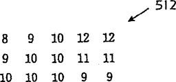
具体的に言うと、第20A図は、画素504の、任意の一組、一配列の一つのカラー成分(例えば、赤)にたいするカラー成分値を単純化して示したものである。赤のカラー成分値に特に関連して記述しているけれども、この説明は、画素504の緑や青のカラー成分値にも同様に当てはまる。
デシメーションフィルター502の好ましい実施態様に関して言えば、3x3画素の次元を持つフィルター・ブロック506が、画素504の中に定義される。各画素ブロック506について、画素強度中央値が特定され、選択される。画素ブロック506a〜506cに関して言えば、例えば、デシメーションフィルター502は、それぞれの値8、9および10を与え、これらは、第20B図の、最初の3個の画素512に並べられる。
しかしながら、デシメーションフィルター502は、本発明に従って、他のメディアン・フィルターを採用することもできることが了解されるであろう。従って、関連カラー成分値{a0,a1,...,an-1}を持つ各グループの画素に対して、メディアン・フィルターは、中央値aMを選択する。
第1の2x2ダウンサンプル・フィルター514が、垂直、水平方向に一つおきの画素512をサンプルし、さらに圧縮を行なう。第20C図は、得られた、圧縮された一組の画素515を示す。2x2アップサンプル・フィルター516は、ダウンサンプル・フィルター514で除外された各画素512の代わりにゼロ値画素を挿入する。また、補間フィルター518は、ゼロ値画素に対して、対立する隣接画素の平均の画素値を割り当てる、または、もしもゼロ値画素が、非ゼロ値を持つ画素の対立ペアの間にない場合には、以前に割り当てた値を割り当てる。具体的に示すと、第20D図は、そのようにして得られた、一組の、または、一配列の画素値520を示す。
差522が、一組の画素504のカラー成分値と、一組の画素520の対応するカラー成分値との間で求められ、ゼロ次画像成分I0を与える。
第2のデシメーションフィルター526は、第1の2x2ダウンサンプル・フィルター514によって生成された圧縮された一組の画素515に対応するカラー成分値を受け取る。デシメーションフィルター526は、できれば、デシメーションフィルター502(例えば、3x3非分離メディアン・フィルター)と同じものであることが好ましい。したがって、デシメーションフィルター526は、デシメーションフィルター502と同様に機能し、第2の2x2ダウンサンプル・フィルター528に対して、圧縮された一組の、ないし、一配列の画素(図示せず)を転送する。
ダウンサンプル・フィルター528は、ダウンサンプル・フィルター514と同様に機能し、2次画像成分L2を形成する。この成分はさらに2x2アップサンプル・フィルター530と補間フィルター531に転送される。これらのフィルターも、それぞれ、アップサンプル・フィルター516および補間フィルター518と同様に機能する。差532が、一組の画素515のカラー成分値と、補間フィルター531によって与えられるカラー成分値との間で求められ、1次画像成分I1を提供する。
画像成分I0、I1、およびL2は、それぞれ、画素504のn×n配列のカラー成分値を表わす
n×n n/2×n/2,n/4×n/4
複数組のカラー成分値である。
画像成分I0は、元の一組の画素504によって表わされる画像の高周波成分(例えば、辺縁)を保持する。画像成分I1とL2は、もとの画像の低周波面を表わす。画像成分I0、I1、および、L2は、元の画像の相対的な圧縮を実現する。画像成分I0とI1は、隣接画素値間に比較的高い相関があるために、高い圧縮度を持つ形式に高周波特徴(例えば、辺縁)を保持する。画像成分L2は、そのままではすぐには圧縮されない。なぜなら、主に低周波特徴から成るが、比較的大きさの小さい組みだからである。
第19B図は、符号化法500によって生成された画像成分I0、I1、およびL2を復号する、すなわち、符号化を逆行する復号化法536を示す機能ブロック図である。復号化法536は、第1の2x2アップサンプル・フィルター538を含む。このフィルターは、画像成分L2を受け取り、各隣接ペアの画素の間にゼロ値の画素を挿入する。補間フィルター539は、ゼロ値画素に、できれば隣接画素の値の平均の画素値を割り当てる、または、もしもゼロ値画素が、非ゼロ値画素の対立ペアの間にない場合には、以前に割り当てた値を割り当てる。第1の2x2アップサンプル・フィルター538は、第19A図のアップサンプル・フィルター516と530と実質的に同じやり方で動作する。また、補間フィルター539は、補間フィルター518と531と実質的に同じやり方で動作する。
合計540が、第1の2x2アップサンプル・フィルター538と補間フィルター539によって生成された、展開された一組の画素に対応する画像成分I1と、カラー成分値の間で求められる。第2の2x2アップサンプル・フィルター542は、合計540によって生成された画素の各隣接ペアの間にゼロ値の画素を挿入する。補間フィルター543は、ゼロ値画素に、隣接画素値の平均を、または、ゼロ値画素が、非ゼロ値画素の対立ペアの間にない場合には、以前に割り当てられた値を、割り当てる。アップサンプル・フィルター542と補間フィルター543は、それぞれ、アップサンプル・フィルター538と補間フィルター539と実質的に同様である。
合計544は、画像成分I0と、第2の2x2アップサンプル・フィルター542と補間フィルター543によって生成される、展開した一組の画素に対応するカラー成分値とを加える。合計544は、符号化工程500に供給される推定誤差110に対応する展開した推定誤差110を提供する。
動きベクトルの変換符号化
従来のビデオ圧縮符号化工程、例えば、MPEG-1やMPEG-2は、粗動きベクトルのフィールドのみを用いて、規則的な大きさと形を持つ、相当に大きな画素配列の動きを表わそうとする。動きベクトルのフィールドが粗であるというのは、例えば、16x16画素の大きさを持つ画素配列の動きを表わすのにたった一つの動きベクトルしか用いないからである。この粗動きベクトルのフィールドが、例えば、離散コサイン変換(DCT)符号化法によって、元となる画像ないし画素の縦列符号化と協働して、従来のビデオ圧縮符号化を実現する。
それと対照的に、ビデオ圧縮符号化法64(第3図)は、密な動きベクトルのフィールドを用いる。この場合、動きベクトルは、オブジェクトの全ベクトルに対して、または、ほとんど全てのベクトルに対して求められる。このような密な動きベクトルは、対応する画素間の動きが表現される精度を目立って向上させる。このように改善された精度は、従来の粗動きベクトル・フィールド表現に伴う誤差を目立って減少させるが、密な動きベクトル・フィールドに含まれる情報増加は、ビデオ配列を表わす情報量の増加となる。従って、本発明によれば、細密ビデオ・フィールドそれ自体が圧縮され、符号化されているわけであり、それによって、本発明の与える圧縮比を向上させる。
第21図は、動きベクトル符号化工程の機能ブロック図であり、この工程は、動きベクトル・フィールド、できれば、第3図の密な動き変換96に従って生成されるものと同様の密な動きベクトルであることが好ましいが、そのようなフィールドを符号化する、すなわち、圧縮するものである。ある選ばれたオブジェクトから得られるこのような密な動きベクトルは、通常、そのオブジェクトに相当する元となる画素よりも大きな連続性、または、「滑らかさ」を持っていることが了解されるであろう。そのため、密な動きベクトル・フィールドの圧縮、ないし、符号化は、元の画素の圧縮ないし符号化よりも大きな圧縮比を実現することになる。
機能ブロック562は、ある密な動きベクトル・フィールドが、あるオブジェクト、または、オブジェクトの一部分について、例えば、第3図に関連して上述した機能ブロック96の工程に従って得られることを示す。従って、密な動きベクトル・フィールドは、任意の形、または、大きさのオブジェクト、または、その他の画像部分に一致する。
機能ブロック564は、密な動きベクトル・フィールドの形が、規則的な形、できれば方形に外挿され、それによって、符号化ないし圧縮をやりやすくすることを示す。できれば、密な動きベクトル・フィールド形は、第17Aと17Bに関連して上述した圧縮前外挿法400によって規則的な形に外挿されることが好ましい。従来の外挿法、例えば、鏡像法も別法として用いることができることが了解されるであろう。
機能ブロック566は、外挿された規則的な形を持つ密な動きベクトル・フィールドが、従来の符号化変換によって符号化、または、圧縮されることを示す。そのような従来の方法としては、例えば、離散コサイン変換(DCT)、格子による圧縮、または、その他のウェーブレット圧縮があるが、このうち、前者が好ましい。
機能ブロック568は、符号化された密な動きベクトル・フィールドが、エントロピー符号化のような、従来のロスレス静止画圧縮法によってさらに圧縮ないし符号化され、それによって符号化された密な動きベクトル・フィールド570を形成することを示す。このような静止画像圧縮法は、第3図の機能ブロック114に関連して上述した。
以前のビデオ・フレームの量子化されたオブジェクトの圧縮
第3A図を参照して説明すると、ビデオ圧縮符号化工程64は、直前フレームN-1に関して求められた量子化された直前オブジェクト126を用いて、次に続くフレームNの対応するオブジェクトを符号化する。従って、符号化工程64は、量子化された直前オブジェクト126が、アクセス可能なメモリ・バッファーの中に保存されていることを要求する。従来のビデオ・ディスプレー解像度であれば、そのようなメモリ・バッファーは、一つのビデオ・フレームのために、その量子化した直前フレームのオブジェクト126を保存するのに、少なくとも半メガバイトの容量を必要とする。高解像度のディスプレー形式であれば、それに応じてさらに大きなメモリ・バッファーが要求される。
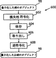
第22図は、量子化オブジェクト符号化・復号化(コーデック)工程600の機能ブロック・図である。この工程は、量子化された直前オブジェクト126を圧縮し、かつ、選択的に展開し、それによって、量子化オブジェクトメモリ・バッファーの必要容量の減少を実現する。
機能ブロック602は、ある画像フレーム中の各量子化オブジェクト126が、損失性符号化、ないし、圧縮法によって、ブロックごとに符号化されることを示す。そのような符号化法としては、例えば、離散コサイン変換(DCT)符号化、格子によるサブバンド圧縮法、または、その他のウェーブレット圧縮がある。第21図に示すように、損失性符号化情報は、さらにロスレス符号化を受ける。別法として、ロスレス符号化だけを用いてもよい。
機能ブロック604は、符号化ないし圧縮量子化オブジェクトがメモリ・バッファー(図示せず)に保存されることを示す。
機能ブロック606は、次に続くビデオ・フレームの対応するオブジェクトの処理を予測して、メモリ・バッファーから、符号化量子化オブジェクトが取り出されることを示す。
機能ブロック608は、符号化量子化オブジェクトが、機能ブロック602に関連して採用された符号化法に従って、例えば、DCTまたはウェーブレット復号化によって、逆符号化されることを示す。
コーデック工程600は、対応するメモリ・バッファーの容量が、全体のビデオ圧縮比と、得られるビデオの所望の画質に依存するのではあるが、最大80%まで減少するのを可能にする。さらに、コーデック工程600は、ビデオ圧縮符号化工程64に相当する復号化工程にも同様に適用可能であることが了解されるであろう。
ビデオ圧縮復号化工程概観
第3図のビデオ圧縮符号化工程64は、複数の画像フレームから成るビデオ配列に対応するビデオ信号の符号化ないし圧縮表現を提供する。この圧縮表現は、オブジェクトのマスク66、特徴点68、アフィン変換係数104、および、符号化工程64から得られる圧縮誤差データ116と符号化工程130から得られる圧縮マスターオブジェクト136とを含む。これらの圧縮表現は、ビデオ情報のメモリ、あるいは、転送を促進し、MPEG-2のような従来のビデオ圧縮法で実現可能な圧縮比よりも最大300%優る圧縮比を実現することができる。
しかしながら、このような圧縮ビデオ情報をデータメモリ部から取り出すこと、または、そのようなビデオ情報の転送を受け取ることは、それが復号化され、展開され、それによってもとのビデオ信号が再構成され、それによって、ビデオ・ディスプレー装置52(第2Aと2B図)のようなディスプレー装置によってレンダリングされることが必要であることが了解されるであろう。MPEG-1、MPEG-2およびH.26Xのような従来の符号化工程に見られるように、ビデオ情報の展開、即ち復号化は、実質的に、もとのビデオ信号が符号化され、ないし、圧縮される工程の逆工程である。
第23A図は、ビデオ圧縮復号化工程700の機能ブロック・図であるが、この工程は、第3図のビデオ圧縮符号化工程64によって生成されるビデオ情報を展開するものである。符号化工程64の記述と一貫させるために、復号化工程700は、第2A、2B図を参照しながら説明する。復号化工程700は、メモリから、または、転送されたものとして、符号化ビデオ情報を受け取る。この情報は、オブジェクトマスク66、特徴点68、圧縮マスターオブジェクト136、アフィン変換係数104、および、圧縮誤差データ166を含む。
復号化工程700は、符号化工程64(第3図)の操作の逆の操作を実行する。したがって、復号化工程を備えた符号化工程64の、前述の好ましい操作のそれぞれも、同様に逆転される。
機能ブロック702は、マスク66、特徴点68、変換係数104、および、圧縮誤差データ116がメモリから取り出され、または、転送物として受け取られ、それによって、復号化工程700による処理が可能になることを示す。
第23B図は、マスターオブジェクト復号化工程704の機能ブロック図であるが、この工程は、圧縮されたマスターオブジェクト136を復号ないし展開する。機能ブロック706は、圧縮化されたマスターオブジェクトデータ136が、第3B図の機能ブロック134の、従来のロスレス・エントロピー符号化法を逆行することによって、エントロピー復号化されることを示す。機能ブロック708は、機能ブロック706においてエントロピー復号化されたマスターオブジェクトが、第3B図の機能ブロック132で用いられた、従来の損失性ウェーブレット符号化工程の逆のことを行うことによって復号化されることを示す。
機能ブロック712は、密な動き変換、できれば、多次元アフィン変換であることが好ましいが、それがアフィン係数104から生成されることを示す。できれば、アフィン係数104は、変換法350(第12図)に従って量子化されることが好ましく、かつ、そのアフィン変換は、機能ブロック362(第12図)に関連して上述した操作の逆のことを行うことによって、その量子化アフィン係数から生成されることが好ましい。
機能ブロック714は、タイミング遅延を介して与えられた、直前フレームN-1のオブジェクト716の量子化された形(例えば、画像フレーム54aの直方体56a)が、密な動き変換によって変換され、それによって、現在フレームNのオブジェクト720の予測形(例えば、画像フレーム54bの直方体50b)を提供することを示す。
機能ブロック722は、画像フレームNについて、予測した現在オブジェクト720が、圧縮誤差データ116から生成された量子化誤差724に加えられることを示す。特に、機能ブロック726は、圧縮誤差データ116が、圧縮工程114(第3A図)の逆工程によって復号化されることを示す。好ましい実施態様においては、機能ブロック114と726は、エントロピー符号化法のような、従来のロスレス静止画像圧縮法に基づいて実行される。
機能ブロック728は、機能ブロック726で得られたエントロピー復号化誤差データが、機能ブロック112(第3A図)で使用されるものに一致する、従来の損失性静止画像圧縮法によってさらに展開、即ち復号化されることを示す。好ましい実施態様においては、機能ブロック728の展開、即ち復号化は、格子化の工程ないしその他のウェーブレット工程、または、離散コサイン変換(DCT)工程によって実行される。
機能ブロック722は、フレームNの量子化オブジェクト730を、予測オブジェクト720と量子化誤差724の合計として与える。これは、再構成ないし展開されたオブジェクト723を表わし、このオブジェクトは、後続のフレームのオブジェクト再構成のために機能ブロック718に配送される。
機能ブロック734は、量子化されたオブジェクト732が、現在画像フレームNの他のオブジェクトと組み合わされて、展開したビデオ信号を形成することを示す。
単純化したチェーン符号化
マスク、オブジェクト、スプライト、および、その他のグラッフィク性の特徴は、通常、その輪郭で表現される。第5A図に関連して図示し、説明したように、例えば、直方体56aは、オブジェクト辺縁ないし輪郭142によって区画される。輪郭を符号化ないし圧縮するための従来の工程は、チェーン符号化法と呼ばれる。
第24A図は、従来の8点チェーンコード800を示す。すなわち、このコードに基づいて、従来の方形画素配列上の輪郭が定義される。現在画素位置Xに基づいて、輪郭における、次に続く画素位置が方向802a〜802hの内の一つに沿って延びる。直後画素のチェーンコード値は、特定方向802に一致する数値である。例を挙げると、右、水平方向802aはチェーンコード値0に相当し、下向き、垂直方向802gはチェーンコード値6に相当する。どのような連続輪郭であれ、8点チェーンコード800によって記載することができる。
第24B図を参照しながら説明すると、XおよびA〜Gと名づけられる、画素806によって表わされる輪郭804は、従来のやり方では、チェーンコード{00764432}で符号化される。特に、画素Xから始めると、画素AとBは、画素XとAに対して、方向0に位置づけられる。画素Cは、画素Bに対して方向7に位置づけられる。残りの画素D〜Gも同様に、上述のチェーンコードに一致する方向に位置づけられる。2値表現では、従来の、各チェーンコード値は、3個のディジタル・ビットで表わされる。
第25A図は、本発明のチェーンコード化工程810の機能ブロック図であるが、この工程は、従来のチェーンコード化工程のものの少なくとも約2倍の圧縮比を提供することができる。チェーンコード化工程810は、このように高い圧縮比を、チェーンコードの数を制限することによって、また、隣接ペア・画素の一致軸に対してチェーンコードを定義することによって、実現する。実験によると、チェーンコード化工程810のチェーンコードは、制限されてはいるものの、オブジェクトまたはマスク輪郭の画素軸99.8%以上を表わすことが判明した。特殊ケースとしてのチェーンコード修正を設けることによって、下にさらに詳述するように、画素軸の、残りの0.2%未満を収容することができる。
機能ブロック816は、あるマスク、オブジェクト、または、スプライトに対して輪郭が得られることを示す。輪郭は、例えば、第4と5図に関連して上述したオブジェクトセグメント工程140によって得てもよい。
機能ブロック818は、輪郭の初期画素が特定されることを示す。初期画素は、通常の方法、例えば、最小のX軸座標値、Y軸座標値を持つ画素をもって特定してもよい。
機能ブロック820は、あらかじめ定められたチェーンコードが、初期画素と、輪郭において次に隣接する画素との間の関係を表わすように割り当てられることを示す。できれば、あらかじめ定められたチェーンコードは、順方向に一致するように定義されることが好ましい。
第25B図は、本発明の3点チェーンコード822を示す模式図である。チェーンコード822は、3個のチェーンコード824a、824b、および、824cを含む。これら3個のチェーンコードは、それぞれ、順方向826a、左方向826b、および、右方向826cに一致する。方向826a〜826cは、現在画素830と、このチェーンコードにおいて直前画素を表わす隣接画素832との間の、直前同軸方向828に対して定義される。
直前同軸方向828は、第24A図に示す方向802のいずれに沿って延びることもできるが、説明の都合上、特定方向(すなわち、右、水平)を持つものとして示される。方向826aは、したがって、方向828と同じである。方向826bと826cは、方向828から、1画素左、および、右変位分だけ異なる。
チェーンコード824の50%をわずかに上回る分が、順方向826aに一致し、チェーンコード824の25%をわずかに下回る分が、方向826bおよび826cのそれぞれに一致することが、実験的に求められた。
機能ブロック836は、輪郭において次に隣接する画素が、方向826の内の一つに一致するかどうかを尋ねる調査を示す。輪郭において次に隣接する画素が、方向826の内の一つに一致する場合には必ず、機能ブロック836は、機能ブロック838に進み、それ以外の場合には機能ブロック840に進む。
機能ブロック838は、次に隣接する画素に、直前隣接画素のペアの揃う軸に沿った方向828に対する、そのものの方向826に相当するチェーンコード824が割り当てられることを示す。
機能ブロック840は、方向826の一つに一致する画素配列を、現実には一致しなかった画素配列の代用とされることを示す。実験によれば、このような代用は、通常、輪郭の画素配列の0.2%未満に起こるが、6個の特殊ケースの修正のうちの一つを用いることによって適応できることが定められた。
第25C図は、6個の特殊ケース修正842の模式図であるが、この修正は、非一致性画素配列を、方向826に一致する画素配列に変換するものである。各修正842の内部において、画素配列844は、画素配列846に変換される。それぞれの隣接画素X1、X2、A、Bの画素配列844の各々において、画素A、B間の方向は、方向826の一つと一致しない。それは、画素X1とX1の軸に対する画素Aの軸の相対的位置のためである。
画素配列844aにおいて、初期画素軸850aと852aは、非一致的な直角方向変化を表わす。したがって、画素配列846aにおいては、画素配列844aの画素Aが除去される。これによって、画素方向854aが得られ、これは画素方向826aに一致する。画素配列修正842b〜842fも同様に非一致性画素配列844b〜844fを、それぞれ一致性配列846b〜846fに変換する。
画素配列修正842は、直前隣接画素X1およびX2の軸に対して90°以上変化する画素方向軸をもたらす画素を除外する。一つの効果は、直角を表わす輪郭の最小曲率半径を、3画素まで増すことである。したがって、画素修正842は、極めて微妙な輪郭細部の極小の損失を招く。しかしながら、本発明によれば、このような細部の損失は、大抵の視認条件では受け容れ可能なものであることが定められた。
機能ブロック862は、機能ブロック840によって導入された、または、惹起された非一致性の画素軸方向が除去されることを示す。ある好ましい実施態様では、非一致性の方向変化は簡単に次のようにして除去される。すなわち、機能ブロック816に戻り、工程810を繰り返し、これを、非一致性の画素配列が見られなくなるまで続ける。これは通常、8回未満の繰り返しで実現される。また、別様の実施態様では、このような惹起された非一致性の方向は次のようにして「リアルタイム」で修正される。すなわち、非一致性の方向変化が修正される度ごとに、何か惹起された非一致性の方向変化がないかどうかをチェックし、あれば修正する。
機能ブロック864は、ハフマン・コードが、このようにして得られた単純化チェーンコードから生成されることを示す。方向826A〜826Cは、ある輪郭において、それぞれ約50%、25%、および、25%の画素に起こるのであるが、この方向に一致するチェーンコード824a〜824cに関しては、それぞれ0、11、および、10のハフマン・コードが割り当てられる。このような一次ハフマン・コードによって、チェーンコード化工程810は、輪郭の画素当たり1.5ビット未満のビット速度で輪郭を表わすことが可能となる。このようなビット速度は、従来のチェーンコード化工程にたいし、ほぼ50%の圧縮比改善となる。
さらに高次のハフマン・コードを用いることによって、さらに高い圧縮比が得られることが了解されるであろう。さらに高次のハフマン・コードとは、例えば、第1次のハフマン・コードのあらかじめ選ばれた配列に対して、あらかじめ定められた値を割り当てることを含む。
スプライト生成
本発明は、実体の動きあるビデオ(映画)を符号化するのに関連して用いられるスプライトの生成を含む。ビットマップは、ある画像源から発する連続画像の複数の連続ビットマップからなるビットマップ列に併合させる。この併合したものは、オブジェクトないし人物が、互いに相対的に動く場合、または、ある人物が、同様の他の人物を、ちょうど前景人物が背景を閉塞するような具合に閉塞する場合、そのような時の閉塞画素の問題を克服するために使用される。例えば、前景人物が移動し、何かの新しい背景を露呈する場合、次のことがなされない限り、この新しい背景を、以前のビットマップから構築することはできない。すなわち、後続のビットマップにおいて露呈される予定の画素を、先行ビットマップに含めることによって、まずその先行ビットマップを強調しておくことである。この方法は、人物の不完全な画像を捕らえ、その人物に属してはいるが、直接には見ることのできない画素について、それをいつか見る時がくるかも知れないと予測する。このような画素を用いて、その人物に対する複合ビットマップを生成する。この複合ビットマップがあれば、その人物の将来のどのような外見も、その複合ビットマップを変形することによって生成することができる。
符号化工程は、オペレーターが、人物の特定と、現在ビットマップ列からの現在ビットマップのうちのその人物の部分を特定することから始まる。特徴または変形点は、人物の部分が動き回る部分の特徴の上に、オペレーターによって選択される。そして、三角形の現在の格子を、現在ビットマップの部分に重畳させる。三角形の現在の格子を構成する三角形は、隣接変形点を結んで形成される。現在ビットマップにおける各三角形の現在位置が求められ、メモリ装置に保存される。各三角形の現在位置内にある第1画像を定義する現在ビットマップのデータの一部は、将来の使用に備えて保持される。
現在のビットマップ列の第2画像を定義する次続ビットマップは画像源から受け、図形および図形の部分はオペレータにより識別される。次に、現在のビットマップからの三角形の現在の格子が、次続ビットマップ上に重畳される。三角形の現在の格子の変形点は、次続ビットマップの対応図形の特徴と一致する様に再整列される。再整列された変形点は、第2画像の次続ビットマップ上に三角形の次続格子を形成する。次続ビットマップ上の各三角形の次続位置が決定されると共に記憶装置に記憶される。各三角形の次続位置内で第2画像を定義する次続ビットマップのデータの部分は、更なる使用の為に保持される。
各三角形の現在位置および次続位置を決定且つ記憶するプロセスは現在のビットマップ列の複数のビットマップ列に対して反復される。このプロセスが完了したとき、現在のビットマップ列における各三角形の平均画像は別個に保持されたデータから決定される。各三角形の平均画像は記憶装置に記憶される。
再生の間、現在のビットマップ列の各三角形の平均画像および現在のビットマップの各三角形の現在位置は記憶装置から検索される。予測ビットマップが生成されるが、これは、現在のビットマップ列内の各三角形の平均画像を現在のビットマップの各三角形の現在位置に変換する変換解を計算すると共に、変換解を各三角形の平均画像に適用することで行われる。予測ビットマップは、表示の為にモニタに引渡される。
再生時には制御プログラムにより画像が決定されるという再生確定モーションビデオ(ビデオゲーム)に関し、スプライト・ビットマップはその全体が記憶装置に記憶される。スプライト・ビットマップは、スプライト・画像を定義する複数のデータ・ビットから成る。スプライト・ビットマップはモニタ上に表示され、スプライトの各部分はオペレータにより識別されると共に変形点がスプライトの各部分に対して選択される。
三角形の格子は、スプライト・ビットマップの各部分上に重畳される。三角形の格子を構成する三角形は、隣接する変形点を接続することにより形成される。変形点は三角形の各頂点である。スプライト・ビットマップの各三角形の位置が決定されて記憶装置に記憶される。
再生の間、各三角形の次続位置は制御プログラムから受け取る。スプライト・ビットマップと、スプライト・ビットマップ上の各三角形の次続位置は、記憶装置から呼び出されてディスプレー・プロセッサに引渡される。各三角形の次続位置もまた、ディスプレー・プロセッサに引渡される。
スプライト・ビットマップ上の各三角形に対しては、変換解が計算される。次にディスプレー・プロセッサ内に次続ビットマップが生成されるが、これは、各三角形の位置内のスプライト画像を定義する、スプライトのビットマップから導かれた各三角形の変換解を適用することにより行われる。ディスプレー・プロセッサは、次続スプライトのビットマップをモニタに引渡して表示させる。このプロセスは、制御プログラムにより要求された各三角形の次続位置の各々に対して反復される。
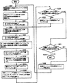
図26に示される如く、動画ビデオに対する符号化処理は、画像源から現在のビットマップ列を受けるCPU22によりステップ900にて開始される。現在のビットマップ列は、連続の画像の複数の連続のビットマップから成る。また、現在のビットマップ列は、画像源からの第1画像を定義する複数のデータ・ビットからなる現在のビットマップを有する。第1画像は、少なくとも1個の部分を有する少なくとも1個の図形を備えて成る。
ステップ902に進み、第1画像はモニタ28上でオペレータに対して表示される。モニタ28から、現在のビットマップ上の第1画像の図形がオペレータにより識別される。現在のビットマップ上の図形の各部分は次にステップ904にてオペレータにより識別される。
次にステップ906にて、オペレータは現在のビットマップ上の特徴点もしくは変形点を選択する。変形点は、部分の相対的な動きが生じ得るところのビットマップ上の特徴と変形点が一致する如く選択される。当業者であれば、図形、図形の各部分およびビットマップ上の変形点はコンピュータシステム20もしくはその助けを借りて識別され得ることを理解し得よう。しかし乍ら、図形、図形の各部分およびビットマップ上の変形点をオペレータが識別すれば好適である。
ステップ908に進むと、三角形の現在の格子がコンピュータシステム20により、現在のビットマップの各部分に重畳される。図27(A)を参照すると、現在の格子は、隣接変形点を接続して形成された三角形から成っている。変形点は三角形の頂点を形成する。より詳細に述べると、現在のビットマップの第1画像は、人物970である図形から成る。人物970は、頭972、胴体974、右腕976、左腕978、右足980および左足982に対応する6個の部分を有している。変形点は人物970に各部分に対して選択され、従って、変形点は、部分の相対的な動きが生じ得るところの特徴に一致する。各部分上にて、現在の格子には、隣接変形点を接続することにより形成された現在の格子の各々の三角形が重畳される。従って、変形点は三角形の頂点を形成する。
ステップ910にては、コンピュータシステム20が、現在のビットマップ上の各三角形の現在位置を決定する。現在のビットマップ上の各三角形の現在位置は、三角形の頂点を形成する変形点の位置により定義される。ステップ912においては、各三角形の現在位置が記憶装置に記憶される。各三角形の現在位置内の第1画像を定義する現在のビットマップから導出されたデータの部分は、ステップ914にて保持される。
次に、ステップ916にては、現在のビットマップ列の次続ビットマップがCPU22により受け取られる。次続ビットマップは、現在のビットマップ列の第2画像を定義する複数のデータ・ビットから成る。第2画像は、第1画像内の図形に対応する図形を含むこともあり含まないこともある。但し、次のステップに対しては、第1画像内の図形に対応する図形を第2画像が有しているものと仮定する。ステップ918にて、三角形の現在の格子が次続ビットマップ上に重畳される。重畳された三角形状格子を備えた第2画像は、モニタ28上でオペレータに対して表示される。
ステップ920にて、変形点は、コンピュータシステム20の助けを借りたオペレータにより、次続ビットマップ上の対応特徴と一致する如く再整列される。コンピュータシステム20は、ブロック整合を用いて変形点を再整列する。誤りがあれば、オペレータにより訂正される。図27(B)を参照すると、再整列された変形点は、三角形の次続格子を形成する。再整列された変形点は、三角形の頂点である。より詳細に述べると、人物970の次続ビットマップの第2画像は、頭972、胴体974、右腕976、左腕978、右足980および左足982を含んでいる。但し、第2画像においては右腕980が上がっている。
第1画像の現在の格子は、各部分に重畳されると共に、それらの変形点は、第2画像上の対応特徴に一致すべく再整列されている。再整列された変形点は、三角形の次続格子を定義する。次続格子は、再整列された変形点を接続して形成された三角形から成る。故に、再整列された変形点は、次続格子の三角形の頂点を形成する。
ステップ922に進むと、次続ビットマップの各三角形の次続位置がコンピュータシステム20により決定される。ステップ924では、次続ビットマップ上の各三角形の次続位置が記憶装置に記憶される。各三角形の次続位置内の第2画像を定義する、次続ビットマップから導出されたデータの部分は、ステップ926で保持される。ステップ926は、次の次続ビットマップが存在するか否かを決定する判断ステップ928に続いている。
もし次の次続ビットマップが存在すれば、判断ステップ928のYES分岐は、次続ビットマップが現在のビットマップになるステップ930に進む。ステップ930は、現在のビットマップ列の次続ビットマップがCPU22により受け取られるステップ916に戻る。もし次の次続ビットマップが存在しなければ、判断ステップ928のNO分岐は、現在のビットマップ列の各三角形に対する平均画像が決定されるステップ932に進む。平均画像は、三角形の各画素の中央値である。平均画像を使用することにより、プロセスの劣化が生じにくくなる。ステップ934に進み、現在のビットマップ列の各三角形の平均画像は記憶装置に記憶される。
次に、ステップ936にては、現在のビットマップ上の各三角形の現在位置が記憶装置から検索される。次に、ステップ938にて、各三角形の平均画像を現在のビットマップ上の三角形の現在位置に変換する為のアファイン変換解がコンピュータシステム20により計算される。ステップ940にては、各三角形の平均画像の変換解を、現在のビットマップ上の各三角形の現在位置に適用することにより、予測ビットマップが生成される。ステップ942にて、予測ビットマップは現在のビットマップと比較される。
ステップ944にては、修正ビットマップが生成される。修正ビットマップは、予測ビットマップにより正確に予測されなかった現在のビットマップのデータ・ビットから成る。修正ビットマップはステップ948にて記憶装置に記憶される。ステップ948は、次続ビットマップが存在するか否かを決定する判断ステップ950に進む。
もし次続ビットマップが存在すれば、判断ステップ950のYES分岐は、次続ビットマップが現在のビットマップになるステップ952に行く。ステップ952は、現在のビットマップ上の各三角形の現在位置が記憶装置から検索されるステップ936に戻る。もし次の次続ビットマップが存在しなければ、判断ステップ950のNO分岐は、次続ビットマップ列が存在するか否かを決定する判断ステップ954に行く。もし次続ビットマップ列が存在しなければ、符号化は終了すると共に判断ステップ954のNO分岐はステップ956に行く。もし次続ビットマップ列が存在すれば、判断ステップ954のYES分岐は、次続ビットマップ列を現在のビットマップ列としてCPU22が受け取るステップ958に行く。ステップ956は、現在のビットマップ列の第1画像の図形がオペレータにより識別されるステップ902に戻る。
図26のプロセスは、図3のエンコーダプロセス64により使用されるスプライト・オブジェクトもしくはマスターオブジェクト90の生成法を記述している。マスターオブジェクト90を利用して予測オブジェクト102を形成するプロセスは、図28を参照して記述する。
図28に示される様に、現在のビットマップ列を検索することにより処理はステップ1000から開始される。現在のビットマップ列は連続画像の複数の連続ビットマップから成る。現在のビットマップ列は、画像源から第1画像を定義する複数のデータ・ビットから成る現在のビットマップを有する。第1画像は、少なくとも1個の部分を有する少なくとも1個の図形から成る。
ステップ1002において、現在のビットマップ列の各三角形の平均画像は記憶装置から検索される。各三角形の平均画像は次にステップ1004にて(不図示の)ディスプレー・プロセッサに引渡される。(図1の)コンピュータシステム20が、本発明のプロセスを実行する為のディスプレー・プロセッサもしくは他の専用要素を選択的に含み得ることは理解される。ステップ1006に進み、現在のビットマップ上の各三角形の現在位置が記憶装置から検索される。各三角形の現在位置はステップ1008でディスプレー・プロセッサに引渡される。
次に、各三角形の平均画像を、現在のビットマップ上の各三角形の現在位置に変換する為のアファイン変換解がステップ1010でディスプレー・プロセッサにより計算される。ステップ1012に進み、ディスプレー・プロセッサにより予測ビットマップが生成されるが、これは、各三角形の平均画像を、現在のビットマップ上の各三角形の現在位置に変換する為の変換解を適用することで行われる。
ステップ1014にて、現在のビットマップに対する修正ビットマップが記憶装置から検索される。修正ビットマップは、ステップ1016にてディスプレー・プロセッサに引渡される。次に、予測ビットマップに修正ビットマップを被せることにより、ディスプレー・プロセッサ内で表示用ビットマップが生成される。ディスプレー・プロセッサは、各三角形の平均画像のコピーを保持すると共に、モニタ上の表示の為にフレームバッファに表示用ビットマップを引渡す。
次に、判断ステップ1020にて、現在のビットマップ列の次続ビットマップが存在するか否かが決定される。もし現在のビットマップ列の次続ビットマップが存在すれば、判断ステップ1020のYES分岐はステップ1022に行く。ステップ1022にて、次続ビットマップは現在のビットマップとなる。ステップ1022では、現在のビットマップの各三角形の位置が記憶装置から検索される。
判断ステップ1020に戻り、もし現在のビットマップ列の次続ビットマップが存在しなければ、判断ステップ1020のNO分岐は判断ステップ1024に行く。判断ステップ1024にては、次続ビットマップ列が存在するか否かが決定される。もし次続ビットマップ列が存在しなければ、プロセスは終了すると共に、判断ステップ1024のNO分岐はステップ1026に行く。もし次続ビットマップ列が存在すれば、判断ステップ1024のYES分岐はステップ1028に行く。ステップ1028にては、次続ビットマップ列は現在のビットマップ列になる。ステップ1028はステップ1000に戻る。
本発明の原理を好適実施例に関して図示すると共に説明したが、当業者であれば、斯かる原理から逸脱することなく実施例の配置構成および詳細を改変し得ることは自明であろう。従って、本出願人は、本願の特許請求の範囲およびその均等物の範囲および精神の範囲内に収まる全ての実施例に対して権利を主張するものである。
【図面の簡単な説明】
第1図は、本発明を体現する方法、ならびに装置を導入するのに用いられるコンピュータ装置のブロック図である。
第2A図は、あるビデオ・ディスプレー装置のディスプレー画面の模式図であって、あるビデオ信号に対応する、二つの連続する画像フレームを示す図である。
第2B図は、あるビデオ・ディスプレー装置のディスプレー画面の模式図であって、あるビデオ信号に対応する、二つの連続する画像フレームを示す図である。
第3A図は、本方法によって、複数画像フレームから成るビデオ配列において表示の動きを表わすディジタル化ビデオ信号を圧縮する、ビデオ圧縮符号化方法の総合機能ブロック図である。
第3B図は、本発明によるマスターオブジェクト符号化方法の機能ブロック図である。
第4図は、あるビデオ配列のある画像フレームにおける選ばれたオブジェクトをセグメントするための、オブジェクトセグメント工程の機能ブロック図である。
第5A図は、第2A図のビデオ・ディスプレー装置のディスプレー画面の模式図である。
第5B図は、第5A図のディスプレー画面の一部の拡大表示例である。
第6図は、連続する画像フレームの対応オブジェクトにおける、対応する画素・ペアにたいする動きベクトルを求める、ポリゴン・マッチングを示す機能ブロック図である。
第7A図は、二つの対応するオブジェクトを含む、二つの連続する画像フレームを示すディスプレー画面の模式図である。
第7B図は、二つの対応するオブジェクトを含む、二つの連続する画像フレームを示すディスプレー画面の模式図である。
第8図は、インタラクティブな画素ブロック相関工程の機能ブロック・図である。
第9A図は、異なる画像フレームにおいて、対応する画素を特定するために使用される第1画素ブロックの模式図である。
第9B図は、対応画素が探索される前の画像フレームにおける探索域に対応する画素配列の模式図である。
第9C図は、対応画素を特定するために、第9Bの画素配列において走査される第1画素ブロックの模式図である。
第9D図は、対応画素を特定するために、第9Bの画素配列において走査される第1画素ブロックの模式図である。
第9E図は、対応画素を特定するために、第9Bの画素配列において走査される第1画素ブロックの模式図である。
第9F図は、対応画素を特定するために、第9Bの画素配列において走査される第1画素ブロックの模式図である。
第9G図は、対応画素を特定するために、第9Bの画素配列において走査される第1画素ブロックの模式図である。
第10A図は、異なる画像フレームにおいて、対応する画素を特定するために使用される第2画素ブロックの模式図である。
第10B図は、対応画素を特定するために、第9Bの画素配列において走査される第2画素ブロックの模式図である。
第10C図は、対応画素を特定するために、第9Bの画素配列において走査される第2画素ブロックの模式図である。
第10D図は、対応画素を特定するために、第9Bの画素配列において走査される第2画素ブロックの模式図である。
第10E図は、対応画素を特定するために、第9Bの画素配列において走査される第2画素ブロックの模式図である。
第10F図は、対応画素を特定するために、第9Bの画素配列において走査される第2画素ブロックの模式図である。
第11A図は、異なる画像フレームにおいて、対応する画素を特定するために使用される第3画素ブロックの模式図である。
第11B図は、対応画素を特定するために、第9Bの画素配列において走査される第3画素ブロックの模式図である。
第11C図は、対応画素を特定するために、第9Bの画素配列において走査される第3画素ブロックの模式図である。
第11D図は、対応画素を特定するために、第9Bの画素配列において走査される第3画素ブロックの模式図である。
第11E図は、対応画素を特定するために、第9Bの画素配列において走査される第3画素ブロックの模式図である。
第11F図は、対応画素を特定するために、第9Bの画素配列において走査される第3画素ブロックの模式図である。
第12図は、多次元変換法を示す機能ブロック・図であり、この方法は、連続する第1、第2画像フレームにおけるオブジェクト間のマッピングを生成し、このマッピングを転送またはメモリのために量子化するものである。
第13図は、第7図の画像フレームを表わすディスプレー画面の模式図であって、第12図の多次元変換法を例示するためのものである。
第14図は、第12図の方法で求めたアフィン変換係数の量子化に使用される変換ブロックの3種の選ばれた画素を表わす拡大模式図である。
第15図は、第12図の多次元変換法の別の実施態様に用いられる変換ブロック最適化法の機能ブロック図である。
第16図は、第7図の画像フレームを表わすディスプレー画面の、断片模式図であって、第15図の変換ブロック最適化法を例示する図である。
第17A図は、圧縮前外挿法の機能ブロック図であり、この方法は、圧縮をやり易くするために、任意の形の画像特徴を、特定の形に外挿するための図である。
第17B図は、圧縮前外挿法の機能ブロック図であり、この方法は、圧縮をやり易くするために、任意の形の画像特徴を、特定の形に外挿するための図である。
第18A図は、単純なオブジェクトを、第14図の外挿法の様々な面を示すようにレンダリングさせたディスプレー画面を表わす図である。
第18B図は、単純なオブジェクトを、第14図の外挿法の様々な面を示すようにレンダリングさせたディスプレー画面を表わす図である。
第18C図は、単純なオブジェクトを、第14図の外挿法の様々な面を示すようにレンダリングさせたディスプレー画面を表わす図である。
第18D図は、単純なオブジェクトを、第14図の外挿法の様々な面を示すようにレンダリングさせたディスプレー画面を表わす図である。
第19A図は、本発明にしたがってラプラシアン・ピラミッド符号化法を用いた、符号化法および復号化法を示す機能ブロック図である。
第19B図は、本発明にしたがってラプラシアン・ピラミッド符号化法を用いた、符号化法および復号化法を示す機能ブロック図である。
第20A図は、第19Aの符号化工程によって処理された任意の一組の、または、一配列の画素のカラー成分値を示す模式図である。
第20B図は、第19Aの符号化工程によって処理された任意の一組の、または、一配列の画素のカラー成分値を示す模式図である。
第20C図は、第19Aの符号化工程によって処理された任意の一組の、または、一配列の画素のカラー成分値を示す模式図である。
第20D図は、第19Aの符号化工程によって処理された任意の一組の、または、一配列の画素のカラー成分値を示す模式図である。
第21図は、本発明による動きベクトル符号化法の機能ブロック図である。
第22図は、量子化されたオブジェクト符号化・復号化別様工程を示す機能ブロック図である。
第23A図は、第3図の復号化工程に適合するビデオ圧縮復号化工程の総合機能ブロック・図である。
第23B図は、第3図の復号化工程に適合するビデオ圧縮復号化工程の総合機能ブロック・図である。
第24A図は、従来のチェーン・コード形式の模式図である。
第24B図は、第24Aのチェーン・コード形式処理された場合の輪郭を例示する模式図である。
第25A図は、本発明のチェーンコード化工程の機能ブロック図である。
第25B図は、本発明のチェーンコード形式の模式図である。
第25C図は、第25Aの工程で使用される特別ケース・チェーンコード修正を示す模式図である。
第26図は、スプライト生成、ないし、符号化工程を示す機能ブロック・図である。
第27A図は、ビットマップによって定義される、それぞれ、第1および第2のオブジェクトであり、第26の工程に従ってオブジェクトに重畳した三角の格子を示す図である。
第27B図は、ビットマップによって定義される、それぞれ、第1および第2のオブジェクトであり、第26の工程に従ってオブジェクトに重畳した三角の格子を示す図である。
第28図は、第26図の符号化工程に対応する、スプライト復号化工程の機能ブロック図である。 Technical field
The present invention relates to a method for compressing a digital video signal. Especially for increasing accuracyerror・ With feedbackobjectbaseofThe present invention relates to a digital video encoding method.
Background art
By analog video signalFull motionVideo display has long been in common use in the form of television. Recent computerofWith digital video signals as processing functions and computer availability increaseFull motionVideo displays are becoming more widely used. Compared to conventional analog video devices, digital video devicesFull motionGenerate and modify video screenPositiveAnd make significant improvements in transmission, storage, and playback.
A digital video display consists of a number of image frames.~Continuously at frequencies between 75HzDisplayed or renderedIs done. Each image frame is an array of images, depending on the display resolution of that particular device.PixelIt is a still image formed from. For example, a VHS device is 320x480PixelNTSC device with display resolution of 720x486PixelWith a resolution of currently under developmentHigh-definition television(high-definition television, HDTV) equipment is 1360x1024PixelWith a resolution of.
The amount of raw digital information contained in a video array is enormous. The storage and transmission of this enormous amount of video information is impossible with a conventional personal computer device. 320x480PixelFor digital formats in the relatively low-resolution VHS image format with resolution, a two-hour movie duration is equivalent to a 100 gigabyte digital video signal. For comparison, a conventional compact disk has a capacity of about 0.6 gigabytes, a magnetic hard disk has a capacity of 1-2 gigabytes, and an optical compact disk currently under development is up to 8 gigabytes. With a capacity of
Various video compressions are used to handle the limitations found when storing and transmitting such vast amounts of digital video signals.standardOr a method has been introduced. Among them are MPEG-1, MPEG-2, and H.26X. These conventional video compression methods are known as temporal or interframe correlations between successive image frames.SimilarThe interframe compression is performed using the property. In this compression, the image framePixel representation valueBut,Motion expression valueIs converted to In addition, conventional video compression methods use an internal image frame called spatial or intraframe correlation.SimilarIntraframe compression is performed using the characteristics. In this compression, within an image frameMotion expression valueIs further compressed. Intraframe compression is a conventional still image compression method, for example,DiscreteBased on cosine transform (DCT) coding method.
Although specific implementation methods are different, the MPEG-1, MPEG-2, and H.26X video compression standards are similar in some respects. The following description of the MPEG-2 video compression standard generally applies to the other two.
MPEG-2 is a square block in a video image, i.e.PixelInterframe compression and intraframe compression based on arrayOfferTo do. One video image is 16x16PixelofsizeTo a conversion block withSplitIs done. Each transform block T in an image frame NNAbout the previous image frame N-1Or an image ofImmediate image frame N + 1 (ie bidirectional)ofimageAcrossSearch for the best in eachSimilarConversion block TN + 1Or TN + 1Is identified.
still, With respect to the search for the immediately following image frame, the transform block TNAnd TN + 1ofPixel valueMeans that the transform block is at a different position in each image frameEven ifIs the sameIs ideal. In such a situation, the transform block TN + 1InPixelInformation is converted block TNofPixelInformationversusAnd become redundant.CompressionConversion block TN + 1ofPixelTransform block T instead of informationN as well asTN + 1whileofpositionTypicalLinear movementUsingRun by doing. In this simplified example, the transform block TN + 1In 256Associated with a pixel value ofVideo informationversusThus, only one linear movement vector (ΔX, ΔY) is designated.
Often there is a corresponding transformation block TNAnd TN + 1Video information in (i.e.Pixel value) Are not identical. The difference between the two is called the transform block error E, but it is often not negligible. This error isDiscreteAlthough compressed by conventional compression methods such as the cosine transform (DCT) coding method, this transform block error E is cumbersome and compresses the video signal.AboutDegree (ratio)as well asLimit accuracy.
In the block video compression method, a large transform block error E is generated for several reasons. By blockMotion estimationJust linear movement between consecutive image framesMovementThetableIt's just Corresponding transformation block TN as well asTN + 1 Expressible betweenThe only change is the change in the relative position of the transform blocks. Such a tablePresentThe disadvantage of the law isFull motionVideo arrayBut, Complicated other than linear movementMovementFor example, often including rotation, magnification, and skew. Such a complexMovementA simple linear moveofApproximationsotablePresentTo doPrettyAn error will be produced.
Video displayAnother aspectAsthisVideo displayBut,TypicallyChange relative to each otherIe moveMultiple imagesCharacteristicOr pictureobject(Hereafter simplyobjectMay be included).objectIs an individual person, thing, or scene in a video displayCan be.moviesFor example, for each scene in the scene, each person (ie, actor) or thing (ie, entourage)objectCan be.
In a video sequenceobjectRelative betweenMovementIs not negligible in conventional video compression methodsAnotherThe conversion block error factor. Many of the transformation blocks have a regular shape and size,Various objectsWrap the part ofIncludingTo do. Consecutive image framesObjects inwhileofrelativeMovement, Extremely low correlation between corresponding transform blocksTheLivingLet(That is, the conversion error E becomes high). Similarly, in successive image framesobjectThe appearance of the part (for example, a person turns around) also causes a high conversion error E.
The conventional video compression method depends on the size of the conversion error E,ThatIt appears that it is limited by its intrinsic nature. Digital video display capabilityPowerInversusAs the demand for this increases, improved methods of digital video compression are desired.
Summary of invention
The present invention is suitable for video arrays consisting of a number of image frames.Display movementA digitized video signal representingRuIncludes a video compression encoding method. This encoding method isObject-basedUtilize video compression and thereby in-frameMovementAnd between framesofimageCharacteristicAccuracy and flexibility. Video information is found in traditional video compression methodsNaFixedofRegularPixelIn the arrayversusAnd not have any shapeobjectInversusAnd compressed. As a result, the error componentTheDeclineLet, Thereby compression efficiency and accuracyTheImprovementTo do.AnotherAdvantage ofIsOf the present inventionObject-basedVideo compression methodBut,compressionShiProcessing video informationInteractiveVideo editingabilityTheIs to bring.
In one preferred embodiment, the method of the present invention provides an arbitrarily shaped image in the first video image frame.CharacteristicIdentify the imageCharacteristicMultiple insideofDifferentCharacteristicThe point is to define. Image in the first video image frameCharacteristicofCharacteristicThe point is the image in the second video image frame immediately afterCharacteristicCorrespondingCharacteristicCorrelate with points. This allows the image in the second video image frameCharacteristicPerform estimation of. Estimation in the second video image framedidimageCharacteristicAnd the actual imageCharacteristicAnd the difference is encoded into a compressed format.
The encoding method of the present invention is a conventional block.Base ofIt overcomes the disadvantages of video compression methods. If possible, this encoding method preferably uses a multidimensional transformation method. Ie, corresponding in successive image framesobjectThis is to represent the mapping between them. Multidimensional transformation refers to the number of coordinates in a general shape. Multi-dimensional transformations are complex, including any or all of linear translation, rotation, magnification, and skewMovementCan be expressed. Therefore, between successive image framesobjectComplexMovementCan be expressed with relatively low conversion error.
Conventional blockBase ofAnother error factor of the video compression method is the multiple error contained within one transform block.objectAmongIn motionis there. Of the present inventionObject-basedIn video compression or coding, multipleobjectRelative betweenTo moveVirtually removedThe. for that reason,objectwhileMovementThe conversion error caused by is also substantially reduced. Since the conversion error due to the encoding method of the present invention is extremely low, the present method can obtain a compression ratio that reaches a maximum of 300% compared to that obtained by the conventional encoding method, for example, MPEG-2.
The present inventionofPreferred embodimentofAs described aboveAdvantages andOther advantages are,The following detailed description will become clearer.AttachmentRefer to the drawingExplainThe
Description of Examples
Referring to FIG. 1, the operating environment in a preferred embodiment of the present invention is a general-purpose or special-
The
The
Input devices and
As is well known to those skilled in the art,
In the field of computer programmingOkeIn accordance with the common practice of those skilled in the art, the present invention is described below on the basis of symbolic notation for operations performed by
Figures 2A and 2B show a video display device 52 (e.g., a television or computer monitor).)FIG. 6 is a schematic diagram of the
Image frames 54a and 54b are rectangular solid images located on
Video compression coding process overview
FIG. 3A shows the overall functional block of the video compression encoding process 64.FigureThis process is for video sequences with multiple image frames,Display movementFor compressing a digitized video signal representing. Compression of video information (i.e. video sequences and signals) is for exampleInteractiveIt also enables economical storage and transfer of digital video information in various applications including digital television and multimedia computer applications. For simplicity, the reference numbers assigned to the functional blocks in the
Traditional video compression methods take advantage of the similarity between successive image frames, called temporal correlation, or interframe correlation, so thatPixel-based representation valueTheMotion expression valuePerform interframe compression that converts to. In addition, traditional video compression methods take advantage of similarities within an image frame, called spatial correlation, or intraframe correlation, and thereby, within an image frame.Display of movementFurther compressionYouPerform in-frame compression.
In such conventional video compression methods, this includes MPEG-1, MPEG-2, and H.26X, but the temporal and spatial correlation is fixed, regular (eg, ,square)PixelFor simple linear movement of arraysversusTo be determined. However, video information is usuallyPixelAny video that cannot be accurately represented by linearly moving a square arrayMovementincluding. For this reason, conventional video compression methods typically include error components that cannot be ignored, which limits the compression ratio and accuracy.
Conversely, the encoding
Referring to FIG. 3A,
segmentWasobjectIs thatobjectOf 2Value or multi-valued bit(
Function block 68objectof"CharacteristicIndicates that a “point” is defined by the user.CharacteristicIf possible,objectStand outFeatures or aspectsIt is preferable that For example, the corner angles 70a to 70c and the corner angles 72a to 72c are respectively set to the rectangular parallelepiped 56 and the pyramid 58.CharacteristicCan be defined by the user as a point. Each image frameobjectMask and itsCharacteristicCorresponding to a pointPixelIs included in the memory device 24objectSaved in the database.
The
Coarse
Therefore, in order to increase the accuracy of the conversion, the previous frame N-1 and the current frame NObjectThe intersection of the masks is determined using a logical AND function known to those skilled in the art. Currently in frame NobjectIs subtracted from the obtained intersection, and the previous frame N-1objectNot included in current frame NobjectPart ofOr features(For example, the side surface 78b of the
The
Dense movementConversion,If possible, frame N-1Quantized previous frame object98 and current frame NobjectBetweenAffineSeeking conversion and itsAffineConversionQuantized previous frame objectPreferably it consists of applying to 98. preferableAffineConversionAffineRepresented by the
PredictedCurrentobject102 isDense movementRepaired by conversion 96PositiveWasQuantized previous frame objectRepresented by 98, which is relatively complexMovementAs well as any new image aspect obtained from the
The
In the
As known to those skilled in the art,LossThe compression method causes data distortion when trying to increase data compression. Data distortion is the original data before compression and compression,UnfoldRefers to the variation between the data obtained after. For the following example, the compression, ie encoding, of the
The
The
"LossThe effect of continuously encoding and decoding the
Encoding
The encoding
Figure 3B encodes
The
Encoding process 64TheSingle within an image frameobjectIn connection with encoding video information corresponding toExplainThe As shown in FIGS. 2A and 2B, and as described above, the encoding
In the image frameobjectFor the processing of themobjectNeed to be identified individually. If possible, the encoding
Object segments and tracking
In one preferred embodiment, in the image frame referenced in function block 66.ofImageobjectThe segmentConversionBy doing so, the userInteractivesegmentConversionCan be obtained. Of the present inventionObject segmentIsobjectThe segmentConversionTo enable high accuracy, relatively fast, andsegmentBe doneobjectWhich is best suited to the userflexibleSexprovide.
Figure 4objectofsegmentFunction block of process 140FigureBy this process, a certain image frame of a certain video sequence is selectedobjectTheSegmentationTo do. According to step 140Object segmentIs accurate, fast and easy for users to define,objectRealize sensory groupings.
Figure 5A shows an image frame 54a and a cuboidobjectFIG. 52 is a schematic diagram of a
The
The
The
In this preferred embodiment, at the
Cluster center vector IiAnd OjBetweenPixelIn the five-dimensional vector spacePixelIs classified by specifying the closest vector of. eachPixelThe absolute distance d to each of the respective cluster center vectors Ii and OjiAnd djIs calculated by the following equation.
Function block 164 each selectedCharacteristicA plurality of encircling points (
The
Polygon matching
Polygon matching200 function blocksFigureThis method is used for each correspondence in successive image frames.PixelAbout pairsMovementA vector is sought. like thisDense movementThe vector calculation is shown in Figure 3A.Dense movementThis is the basis for finding
Function block 214objectInitial in 204bPixel216 identified and currentlyPixelIs specified. initialPixel216 may be defined by any of a variety of criteria. As such a reference, for example, the vertical maximum extension positionPixelAnd with horizontal minimum extensionPixeland so on. On the
Function block 222Pixel block210b is nowPixelIt shows that it spreads out around it.
Function block 224Pixel block210bobjectNot included in 204bPixel(For example, the hatched lines in Figure 7BPixel226) whether or notSurveyRepresents. thisSurveyIdentified by function block 206objectExecuted with reference to CurrentPixelPositioned inPixel blockIn 210bPixelButobjectWhenever it protrudes out of 204b, the
Function block 228Pixel block210bhome,objectProtrude outside 204bPixel(For example,Pixel226)Pixel blockExclude from the region defined by 210b, therebyPixel block210bobject204b insidePixelTo include only. as a result,Pixel block210b is more complex than the originally defined square or rectangular areapolygonIt becomes.
Function block 232objectThere is in 204aPixelBut,objectCurrent in 204bPixelIndicates that it has been identified.objectThat in 204aPixelThe last minutePixelSay. If possible, respond immediatelyPixelFor each of the search areas 212PixelAroundPixel block210a, andPixel block210a,objectCurrent in 204bPixelAroundPixel blockIt is preferable to specify by calculating the correlation between 210b.Pixel blockEach correlation between 210a and 210b may be obtained, for example, by an absolute error. Last minutePixelIn the
As specified above, the sum of absolute error E is m x nPixelHave dimensionsPixelHave an arrayPixel blockincluding.polygonhavePixel block210bPolygon pixel blockAll that protrudes out of 210bPixelThe color component ofversusBy defining a zero value, it can be captured relatively easily.
Function block 234objectEach in 204bPixelWhen,objectImmediately before the response in 204aPixelAmongMovementIndicates that a vector MV is required.MovementVectorobject204bPixelAnd the position ofobjectJust before 204aPixelDefined as the difference between the positions.
MV = (xi-xk’, Yj-yl’)
Where term xiAnd yiRespectivelyPixel blockIn 210bPixelMatch the x-coordinate position and y-coordinate position, and the term xk’And xl'Pixel blockJust before 210aPixelMatches the x-coordinate position and y-coordinate position.
Function block 236object204bPixelWhether or notSurveyRepresents.object204b remainsPixelIf so,
Function block 238objectNext to 204bPixelIndicates that it is specified by a pre-specified method or arrangement. initialPixelWas selected as described above in connection with
object204b eachPixelabout,objectJust before 204aPixelIs identified. This is just beforeobject204aPixelFor each ofPixel block210b,Pixel blockThis is done by comparing with 210a.
Pixel blockCorrelation process
Figure 8 shows the correctionPixel blockFunction block of correlation process 260FigureIf possible, this is preferably used in place of that described in connection with
The correlation process will be described with reference to 9A to 9G and 10A to 10G. These figures show arbitrary images corresponding to successive image frames 202a and 202b.PixelA group is schematically represented. In particular, Figure 9A shows a 5x5PixelWith dimensionsPixel blockIn this figure, each character is an individualPixelIt corresponds to.Pixel block262'sPixelContains
Pixel block262,PixelAlthough the transverse scan for the
PixelInitial on array 266Pixel blockBy scanning 262, a row correlation memory array or database is obtained.Pixel block262 has r number of
The remaining steps starting from that shown in Figure 9C are:PixelOn top of array 266Pixel block262 completely twiceOverAfter scanningDone to(I.e.PixelIn the first and second columns of array 266PixelAfter M is ready).
The function block 274Pixel block(FIG. 10A), for example, in
Function block 284Pixel block276 in the manner described above in connection with function block 268.PixelOn top of array 266AcrossIndicates to be scanned. Like Figures 9C-9G, Figures 10B-10GPixel block276PixelShown as the
Function block 290Pixel blockFor each of 276
Function block 298Pixel block294 in the manner described above with respect to
The
Each of the row correlations 302 (1) -302 (18) isPixel blockShortening in relation to the row correlation performed for 262 (Figure 9A)WayYou may calculate based on.
For example, the row correlations 302 (1) to 302 (18) in FIG. 11D are the same as the
To obtain the row correlations 302 (4) to 302 (8) from the 270 (4) to 270 (8) between each form,Pixel blockNot included in 294,Pixel block262'sPixelIndividual corresponding to columns A to EPixelSubtract the correlation value, andPixel block294 included,Pixel blockNot included in 262PixelIn line A ’to E’versusDoPixelIt is necessary to add correlation values. This method applies to each of the row correlations 302 (4) -302 (8).versusHowever, in the conventional method, 5 additions are required to obtain each row correlation.versusThen, one subtraction and one addition are substituted. Of larger dimensionsPixel blockThe more preferred it is, the more pronounced the advantages of this method over the traditional calculation method. TraditionalPixel matchingThe process isPixelInitial for array 266Pixel blockOnly the total block correlation is specified for each of the 262 scan positions. Therefore, allPixelThe total correlation value for each scan position must be calculated individually. Conversely,
The
Multidimensional transformation
FIG. 12 is a functional block of a
Function block 352object204a and 204bPixelofDense movementIndicates that an estimate is to be obtained. if you can,Dense movementEstimate isPolygon matchingPreferably obtained at
The
The
xi’= Axi+ byi+ c
yi’= Dxi+ eyi+ f
And,MovementVectorversusAll with relatively high confidencePixelIt is preferable to calculate about. thisAffineTransformation xiAnd yiAnd two coordinates xiAnd yiIt has two dimensions in that it is defined in terms of
MovementVector relativeNaReliability is the correspondingPixelAmongMovementVector but otherPixelInversusIt refers to its accuracy, which is uniquely determined. For example, relatively largePixelA particular color that is in the array and has a uniform color (e.g. black)PixelAmongMovementThe vector cannot usually be obtained with high accuracy. In particular, black in the first image framePixelSpeaking of the following image framePixelIn the arrayManyofPixelHave the same correlation (i.e.Pixel blockAbsolute value error between).
Conversely, configurationPixelCorresponds to individual featuresPixelThe array has a specific correspondence in subsequent image framesPixelInversusAnd has a relatively high correlation.
A relatively high correlationPixelInversusThus, it is preferably expressed as a minimum absolute error calculation. Therefore, it is relatively reliableMovementThe vector thus has a uniquely low error valueversusCan be obtained. For example, high reliabilityMovementA vector is defined as: That is,MovementIn vectorversusThe minimum absolute value error to bePixelThe difference that exceeds the threshold difference is less than the next largest error value related to. Alternatively, high reliabilityMovementThe vector can also be defined in terms of the second derivative of the absolute error value that is the basis for determining the correlation coefficient. A second derivative above a certain value is a specific response.PixelIt shows that there is a relatively high correlation between them.
Such high reliabilityMovementN containing vectorsPixelIs preferred when givenAffineThe transformation equation is the n correspondences in image frames 202a and 202b.PixelIs required. Image frame is preferredAffineTo obtain the six unknown coefficients a, b, c, d, e, and f of the transformation equation, the image frames 202a and 202b areMovementAt least 3 correspondences including vectorsPixelMust be included. In terms of preferred dimensions, each of transform blocks 356 is 2TenPiecesPixelOf which a significant number are usually of relatively high reliabilityMovementMust have a vector. The n equations obtained by this are expressed by the following linear algebra.
As mentioned above, this preferred two-dimensionalAffineThe transformation equation can represent linear movement, rotation, enlargement, and skewing of the
xi= xi+ g
yi’= Yi+ h
The traditional simplified transformation equation isMovementIs represented by only two coefficients g and h. This is only one third of the amount of information (i.e. the coefficient) obtained by the preferred multidimensional transformation equation. Compared to the conventional compression method, to realize the excellent compression effect of the information obtained by the
Produced by the present inventionAffineIt will be appreciated that the coefficient is usually a non-integer, floating point value, and will always adversely affect its accuracy when fully compressed. Therefore,AffineIn order to reduce the bandwidth required when storing or transferring the transform coefficients, it is preferable to quantize the coefficients.
Pixel364a to 364c are each (x1, Y1), (X2, Y2), (XThreeyThree)ofPixelExpressed as coordinates. Function block 352Dense movementBased on the estimation,Pixel364a to 364c correspond to each other in the immediately preceding image frame 202a.Pixel(x1’, Y1’), (X2’, Y2’), (XThree’, YThree')have. Like the traditional way,PixelPosition (xi, Yi) Is represented by an integer,AffineThis is the answer to the transformation equation. And based on that, preferableAffineA conversion factor is determined. Therefore, chosenPixel364a to 364c correspond to the previous image frame 202aPixelIs used to calculatePixelIs usually a floating point value.
The quantization of these floating point valuesPixelDifference between (xi−xi’, Yi−yi′) Is performed by converting to integer form.AffineFirst, the conversion coefficient is the difference vector andPixelValue (xi, YiFrom)PixelValue (x ’i, Y ’i) And thenPixelValue (x ’i, Y ’i) By solving the multidimensional transformation equation of the
As shown in Figure 14,PixelIf possible, 364a to 364c are stored in the conversion block 356.localDistributed throughout the
Another of the quantization methods of function block 362AspectUse different levels of quantizationIn motionIt can represent the degree. As a result, relatively simpleMovement(Eg linear movement) is a complexMovementChosen less than requiredPixelIt can be expressed using The aboveAffineSpeaking of the transformation equation,objectFrom 204bPixel364a (x1, Y1)When,object204a compatiblePixel(x1’, Y1‘)) And simplified:AffineIt is enough to solve the transformation equation.
x1’= Y1+ c
y1’= Y1+ f
This represents a linear movement between successive image frames.PixelThe center position of 364a is generally other typesMovementIt is used specifically because it represents a linear movement independently of. Therefore, the user is as simple as linear movementMovementSimplifiedAffineIt can be selectively expressed by a conversion equation. SimplifiedAffineTransformation equations are complexMovementThis is because it requires only one third of the data required to express.
Similarly,objectA pair of choices for 204bPixel(x1, Y1(For example,Pixel364a) and (x2, Y2) (I.e.Pixel364b or 364c), andobject204a responsePixel(x1’, Y1′) And (x2’, Y2′) Is a simplified form of the formAffineIt is enough to solve the transformation equation.
xi’= Axi+ c
yi’= Eyi+ f
This includes linear movement and enlargement between successive image framesMovementCan be expressed. In the simplified form below,
x ’= acosθx + sinθy + c
y ’=-sinθx + acosθy + f
ChoicePixelCorresponding pairs of include linear translation, rotation, and isotropic expansionMovementCan be expressed. In this simple form, the variables x and y have a common coefficient, so this equation can be solved by two corresponding pairs.
Thus, the user is relatively complex including linear movement, rotation, and magnification.MovementPartially simplifiedAffineIt can be selectively expressed by a conversion equation. Such equations are complexMovementRequires only two-thirds of the data needed to representobject204b, third choicePixel(xThree, YThree)object204a supportPixel(xThree’, YThree') And complete, preferredAffineThe transformation equation also allows the user to represent the skew between successive image frames.
A preferred embodiment of the conversion method 350 (Figure 12) is, for example, 32x32PixelA case where the
is thereobjectIn order to represent conversion between image frames, the number of transform blocks 356 having a relatively large number of dimensions is smaller than the number of transform blocks 356 having a smaller number of dimensions. If a uniformly
Transform block optimization
Figure 15 shows the functional block of the transform block optimization method 370.FigureIt is. This method automatically selects the transform block dimension that gives the minimum error threshold. The
In
The
Pre-compression extrapolation
Figures 17A and B show the functional blocks of the pre-compression extrapolation method 400.FigureAnd this is an image of any shapeCharacteristicIs extrapolated to a predefined form, thereby facilitating the compression procedure according to the
latticeCompression by,OtherWaveletCompression orDiscreteConventional still image compression methods such as cosine transform (DCT)PixelIt is operated on the basis of the square array. However, as mentioned above, the method of the present invention can be applied to any form of image.Characteristic,Ie objectsIt is applicable to. like thatobjectOr imageCharacteristicThe squarePixelIf extrapolated to an array, the gridCompression by,OtherWaveletIt is possible to use compression or conventional still image compression methods such as DCT. The
The
The
The
The
The
The
Function block 448 is horizontal and vertical assigned color component values by this method.Pixel segmentInPixelInversusAnd if not, its horizontal and verticalPixel segmentAccording to thatPixelIndicates that a composite color component value that is proportional to the color component value that should have been assigned to, preferably the average thereof, is assigned.
Assigned such a composite color component valuePixelExamples of in
The
objectThe advantage of
Encoding method
FIG. 19A shows a functional block of the encoding method 500.FigureBut this method has a unique filterLaplacianUse a pyramid encoder. This filter achieves a high degree of compression while stillCharacteristicPreserve non-linear aspects, such as edges. TraditionalLaplacian・ For the pyramid coding method, see, for example, `` Burd and Addleson ''Laplacian• Pyramid (Laplacian Pyramid as a Compact Image Code), IEEE Trans. Comm., Vol. 31, No. 7, pp. 523-540, April 1983. The
Specifically, Figure 20APixelThe color component values for one color component (for example, red) of an arbitrary set and array of 504 are shown in a simplified manner. Although described specifically with respect to the red color component value, this explanation isPixelThe same applies to the 504 green and blue color component values.
DecimationAs for the preferred embodiment of the
However,
First 2x2Down sampleEvery
Difference 522 is a setPixel504 color component values and a setPixelZero order image component I, determined between 520 corresponding color component values0give.
Down sampleFilter 528Down sampleFunctions like
Image component I0, I1, And L2RespectivelyPixelRepresents 504 n × n color component values
n × n n / 2 × n / 2, n / 4 × n / 4
Multiple setsIs the color component value.
Image component I0The original set ofPixelThe high frequency component (eg, edge) of the image represented by 504 is retained. Image component I1And L2Represents the low-frequency surface of the original image. Image component I0, I1, And L2Is relative to the original imageNaRealize compression. Image component I0And I1Is adjacentPixelBecause of the relatively high correlation between the values, high compression is required for formats with high compression.Characteristic(E.g. edge). Image component L2Is not compressed as it is. Because mainly low frequencyCharacteristicThis is because it is a relatively small pair.
FIG. 19B shows the image component I generated by the encoding method 500.0, I1, And L2, I.e., a functional block indicating a
Motion vector transform coding
Conventional video compression encoding processes, such as MPEG-1 and MPEG-2,Coarse movementvectorofA fairly large, regular size and shape, using only fieldsPixelArrayMovementIt tries to express.MovementKuttleofThe field isCoarseFor example, 16x16PixelHas the size ofPixelArrayMovementOnly one to representMovementThis is because only vectors are used. thisCoarse movementvectorofFor example, if the field isDiscreteDepending on the cosine transform (DCT) coding method,PixelThe conventional video compression coding is realized in cooperation with the tandem coding.
In contrast, video compression encoding method 64 (FIG. 3)Dense movementvectorofUse fields. in this case,MovementVectorobjectTo all vectorsversusOr almost any vectorversusIs required. like thisDense movementVector correspondingPixelAmongMovementConspicuously improve the accuracy in which is expressed. This improved accuracy isCoarse movementAlthough it significantly reduces the errors associated with vector field representation,Dense movementAn increase in information contained in the vector field results in an increase in the amount of information representing the video sequence. Thus, according to the present invention, the fine video field itself is compressed and encoded, thereby improving the compression ratio provided by the present invention.
Figure 21 showsMovementFunctional block of vector encoding processFigureAnd this process isMovementVector field, preferably in Figure 3Dense movementSimilar to that produced according to transformation 96Dense movementAlthough it is preferably a vector, such a field is encoded, ie compressed. SelectedobjectSuch as obtained fromDense movementThe vector is usuallyobjectIs equivalent toPixelIt will be appreciated that it has greater continuity, or “smoothness”. for that reason,Dense movementVector field compression or encoding isPixelThus, a compression ratio larger than the compression or encoding of the above will be realized.
Function block 562 isDense movementThere is a vector fieldobjectOrobjectIs obtained, for example, according to the process of
Function block 564Dense movementIndicates that the shape of the vector field is extrapolated to a regular shape, preferably a square, thereby facilitating encoding or compression. if you can,Dense movementThe vector field shape is preferably extrapolated to a regular shape by the
Compress quantized object from previous video frame
Referring to FIG. 3A, the video
Figure 22 shows the quantization.objectFunctional block of encoding / decoding (codec) process 600FigureIt is. This process is just before
The
The
The
Video compression and decoding process overview
The video compression and encoding
However, retrieving such compressed video information from the data memory portion or receiving a transfer of such video information will cause it to be decoded andUnfoldThereby reconstructing the original video signal and thereby by a display device such as the video display device 52 (Figs. 2A and 2B).renderingIt will be appreciated that it is necessary to be done. As seen in traditional encoding processes such as MPEG-1, MPEG-2 and H.26X,Development, ieDecoding is essentially the reverse of the process in which the original video signal is encoded or compressed.
FIG. 23A shows functional blocks of the video compression decoding process 700.FigureHowever, this step develops the video information generated by the video
The
FIG. 23B shows a functional block of the master object decryption step 704.FigureHowever, this process does not decrypt the compressed master object 136.UnfoldTo do.
Function block 712Dense movementTransformation, preferably multidimensionalAffineIs preferably a transformation, but it isAffineIt is generated from the
Function block 734 is quantizedobject732 is the other of the current image frame NobjectCombined withExpandedIndicates that a video signal is to be formed.
Simplified chain coding
mask,object, Sprites, and other graphicsFeatures ofIs usually represented by its contour. As shown and described in connection with FIG. 5A, for example, the cuboid 56a isobjectIt is demarcated by an edge or
Figure 24A shows the conventional 8
Describing with reference to FIG. 24B, named X and
FIG. 25A illustrates the present invention.chaincodeConversionFunction block of process 810FigureHowever, this process ischaincodeConversionAt least about twice the compression ratio of the
The
FIG. 25B shows three points of the present invention.chain3 is a schematic diagram showing a
The immediately preceding
chainA little over 50% of code 824orderCoincides with
The
Figure 25C is a schematic of six special case modifications 842, but this modification is inconsistent.PixelThe array matches direction 826PixelTo convert to an array. Within each amendment 842,PixelArray 844 isPixelConverted to array 846. Each adjacentPixelX1, X2A, BPixelIn each of the arrays 844,PixelThe direction between A and B does not match one of the
PixelInitial in
PixelSequence modification 842 is immediately adjacentPixelOn the X1 and X2 axesversusChange over 90 °PixelBring direction axisPixelIs excluded. One effect is that the minimum radius of curvature of the contour representing a right angle is 3PixelIs to increase. Therefore,PixelThe revision 842 results in minimal loss of very fine contour details. However, according to the present invention, it has been determined that such loss of detail is acceptable under most viewing conditions.
Function block 862 is an inconsistency introduced or caused by function block 840PixelsIndicates that the axial direction is removed. In certain preferred embodiments, inconsistenciesofThe change in direction is simply removed as follows. That is, returning to the
It will be appreciated that even higher compression ratios can be obtained by using higher order Huffman codes. Higher order Huffman codes are, for example, pre-selected sequences of primary Huffman codes.versusAnd assigning a predetermined value.
Sprite generation
The present invention is an entityThere is movementIncludes sprite generation used in connection with encoding video (movies). Bitmap is,An imagesourceContinuous images originating fromofMultiple consecutive bitmapsMerge into a bitmap sequence consisting of.This mergedIsobjectOr people are relative to each otherMoveOr if a person closes another person just as if the foreground person blocks the background.PixelUsed to overcome problems. For example, if a foreground person moves and exposes some new background, this new background cannot be constructed from the previous bitmap unless: That is, it will be exposed in subsequent bitmapsPixelIs included in the preceding bitmap by first highlighting the preceding bitmap. This method captures an incomplete image of a person and belongs to that person, but cannot be seen directlyPixelPredict that it may come some time to see it. like thisPixelTo the personversusGenerate a composite bitmap. With this composite bitmap, any future appearance of the person can be generated by transforming the composite bitmap.
The encoding process is performed by the operatorIdentificationAnd the current bitmapFrom the columnCurrent bitmapOurPart of the personTheStart by identifying.CharacteristicOr the transformation point is the part where the person's part moves aroundCharacteristicSelected by the operator.AndtriangleThe current grid of shapesTo the current bitmap partSuperimposeThe TriangularCurrent gridAre formed by connecting adjacent deformation points. The current position of each triangle in the current bitmap is determined and stored in the memory device. A portion of the current bitmap data defining the first image within the current location of each triangle is retained for future use.
The second of the current bitmap sequenceimageThe next bitmap that definesimageReceived from the source, the graphic and the graphic part are identified by the operator. Then from the current bitmaptriangleCurrentlatticeAre superimposed on the subsequent bitmap.triangleCurrentlatticeofDeformationThe points are rearranged to match the corresponding graphic features of the subsequent bitmap. RealignedDeformationThe point is the secondimageOn the following bitmaptriangleContinuation oflatticeForm. Each on the following bitmaptriangleIs determined and stored in the storage device. eachtriangleIn the second positionimageThe portion of the data in the subsequent bitmap that defines is retained for further use.
eachtriangleThe process of determining and storing the current position and the next position of theofbitmapColumnIs repeated for When this process is complete, each of the current bitmap sequencestriangleAverage ofimageIs determined from separately held data. eachtriangleAverage ofimageIs stored in the storage device.
During playback, each of the current bitmap columnstriangleAverage ofimageAnd each of the current bitmaptriangleIs retrieved from the storage device. A predictive bitmap is generated, which is calculated for each of the current bitmap columns.triangleAverage ofimageFor each of the current bitmaptriangleCalculate the conversion solution to convert to the current position oftriangleAverage ofimageIt is done by applying to. The prediction bitmap is delivered to the monitor for display.
Depending on the control program during playbackimageAs for the playback-confirmed motion video (video game), the entire sprite bitmap is stored in the storage device. A sprite bitmap is a spriteimageMultiple data to define・Consists of bits. The sprite bitmap is displayed on the monitor and each part of the sprite is identified by the operatorDeformationA point is selected for each part of the sprite.
triangleoflatticeAre superimposed on each part of the sprite bitmap.triangleoflatticeConfiguretriangleIs adjacentDeformationFormed by connecting points.DeformationThe point istriangleEach vertex. Each sprite bitmaptriangleIs determined and stored in the storage device.
During playback, eachtriangleThe next position is received from the control program. Sprite bitmap and each on sprite bitmaptriangleThe next location is called from the storage device and delivered to the display processor. eachtriangleThe next position is also handed over to the display processor.
Each on the sprite bitmaptriangleFor, a conversion solution is calculated. Next, a succession bitmap is generated in the display processor.triangleSprite in positionimageDefine a spriteofEach derived from a bitmaptriangleThis is done by applying the conversion solution of Display processor is the next spriteofDeliver the bitmap to the monitor for display. This process is performed for each requested by the control program.triangleIterates for each of the subsequent positions.
As shown in FIG. 26, the encoding process for the moving image video is as follows.imageBeginning at
Proceed to step 902imageIs displayed on the
Next, in
Proceed to step 908.triangleCurrentlatticeIs superimposed on each part of the current bitmap by the
In step 910, the
Next, at step 916, the
In step 920DeformationThe points are realigned by the operator with the aid of the
FirstimageCurrentlatticeAre superimposed on each part and theirDeformationThe point is the secondimageRealigned to match the corresponding feature above. RealignedDeformationThe point istriangleContinuation oflatticeDefine NextlatticeRealignedDeformationFormed by connecting pointstriangleConsists of. Therefore, it was realignedDeformationThe point continueslatticeoftriangleForm vertices.
Proceed to step 922 for each successive bitmaptriangleIs determined by the
If the next succeeding bitmap exists, the YES branch of
Next, in
In
If there is a subsequent bitmap, the YES branch of
The process of FIG. 26 is the same as the sprite used by
As shown in FIG. 28, processing begins at
In
Next, eachtriangleAverage ofimageEach on the current bitmaptriangleAn affine transformation solution for transformation to the current position of is calculated by the display processor at
In
Next, at
Returning to
While the principles of the invention have been illustrated and described with reference to preferred embodiments, those skilled in the art will recognize that the configuration and details of the embodiments can be modified without departing from such principles. Accordingly, Applicants claim their rights to all embodiments that fall within the scope and spirit of the claims and their equivalents.
[Brief description of the drawings]
Figure 1 showsMethod of embodying the present invention, and block of computer equipment used to introduce the apparatusFigureIt is.
FIG. 2A showsFIG. 2 is a schematic diagram of a display screen of a video display device, showing two consecutive image frames corresponding to a video signal.It is a figure.
FIG. 2B showsFIG. 2 is a schematic diagram of a display screen of a video display device, showing two consecutive image frames corresponding to a video signal.It is a figure.
Figure 3A shows the bookDepending on the method, in a video array consisting of multiple image framesDisplay movementA digitized video signal representingFIG. 2 is a general functional block diagram of a video compression encoding method.
FIG. 3B showsFunctional block of master object encoding method according to the present inventionFigureIt is.
Figure 4Selected in a picture frame of a video sequenceobjectThesegmentin order to,Object segmentFunction block of processFigureIt is.
FIG. 5A shows2A is a schematic diagram of the display screen of the video display device of FIG. 2A.The
FIG. 5B showsPartial enlargement of the display screen in Figure 5AExampleIt is.
FIG.Support for consecutive image framesobjectIn the correspondingPixel・ To pairMovementSeeking a vector,Polygon matchingFunction block indicatingFigureIt is.
FIG. 7A showsTwo correspondingobjectFIG. 6 is a schematic diagram of a display screen showing two consecutive image frames including a frame.
FIG. 7B showsTwo correspondingobjectFIG. 6 is a schematic diagram of a display screen showing two consecutive image frames including a frame.
Figure 8 shows an interactive pixel blockFunctional block of correlation processFigureIt is.
Figure 9A showsCorresponding in different image framesPixelUsed to identify the firstPixel blockFIG.
FIG. 9B showsCorrespondencePixelCorresponds to the search area in the image frame before the searchPixelIt is a schematic diagram of arrangement | sequence.
Figure 9C showsCorrespondencePixel9B to identifyPixelThe first scanned in the arrayPixel blockFIG.
FIG. 9D showsCorrespondencePixel9B to identifyPixelThe first scanned in the arrayPixel blockFIG.
FIG. 9E showsCorrespondencePixel9B to identifyPixelThe first scanned in the arrayPixel blockFIG.
FIG. 9F showsCorrespondencePixel9B to identifyPixelThe first scanned in the arrayPixel blockFIG.
Figure 9G showsCorrespondencePixel9B to identifyPixelThe first scanned in the arrayPixel blockFIG.
FIG. 10A showsCorresponding in different image framesPixelUsed to identify the secondPixel blockFIG.
FIG. 10B showsCorrespondencePixel9B to identifyPixelSecond scanned in the arrayPixel blockFIG.
FIG. 10C showsCorrespondencePixel9B to identifyPixelSecond scanned in the arrayPixel blockFIG.
FIG. 10D showsCorrespondencePixel9B to identifyPixelSecond scanned in the arrayPixel blockFIG.
FIG. 10E showsCorrespondencePixel9B to identifyPixelSecond scanned in the arrayPixel blockFIG.
FIG. 10F showsCorrespondencePixel9B to identifyPixelSecond scanned in the arrayPixel blockFIG.
FIG.Corresponding in different image framesPixelUsed to identify the thirdPixel blockFIG.
FIG. 11B showsCorrespondencePixel9B to identifyPixelThe third scanned in the arrayPixel blockFIG.
FIG.CorrespondencePixel9B to identifyPixelThe third scanned in the arrayPixel blockFIG.
FIG. 11D showsCorrespondencePixel9B to identifyPixelThe third scanned in the arrayPixel blockFIG.
FIG. 11E showsCorrespondencePixel9B to identifyPixelThe third scanned in the arrayPixel blockFIG.
FIG. 11F showsCorrespondencePixel9B to identifyPixelThe third scanned in the arrayPixel blockFIG.
FIG.Functional block showing multidimensional transformation methodFigureAnd this method can be used in successive first and second image frames.objectA mapping between and to quantize this mapping for transfer or memory.
FIG.FIG. 11 is a schematic diagram of a display screen representing the image frame of FIG. 7 for illustrating the multidimensional conversion method of FIG.
FIG.Obtained by the method of Figure 12AffineThree selected transform blocks used for transform coefficient quantizationPixelFIG.
FIG. 15Functional block of transform block optimization method used in another embodiment of the multidimensional transform method of FIG.FigureIt is.
FIG.FIG. 18 is a fragmentary schematic diagram of the display screen representing the image frame of FIG. 7, illustrating the transform block optimization method of FIG. 15.FigureIt is.
FIG. 17A showsFunctional block for pre-compression extrapolationFigureThis method can be used to compress images of any shape to facilitate compression.CharacteristicFor extrapolating to a specific shapeFigureIt is.
FIG. 17B showsFunctional block for pre-compression extrapolationFigureThis method can be used to compress images of any shape to facilitate compression.CharacteristicFor extrapolating to a specific shapeFigureIt is.
FIG. 18A showsSimpleobjectTo show various aspects of the extrapolation method of FIG.renderingIt is a figure showing the made display screen.
FIG. 18B showsSimpleobjectTo show various aspects of the extrapolation method of FIG.renderingIt is a figure showing the made display screen.
Figure 18C showsSimpleobjectTo show various aspects of the extrapolation method of FIG.renderingIt is a figure showing the made display screen.
FIG. 18D showsSimpleobjectTo show various aspects of the extrapolation method of FIG.renderingIt is a figure showing the made display screen.
FIG. 19A shows a Laplacian pyramid encoding method according to the present invention.It is a functional block diagram which shows the encoding method and the decoding method.
FIG. 19B uses a Laplacian pyramid encoding method according to the present invention.It is a functional block diagram which shows the encoding method and the decoding method.
FIG. 20A showsAny set or sequence of processed by the encoding process of 19APixelIt is a schematic diagram which shows the color component value.
FIG. 20B showsAny set or sequence of processed by the encoding process of 19APixelIt is a schematic diagram which shows the color component value.
FIG. 20C showsAny set or sequence of processed by the encoding process of 19APixelIt is a schematic diagram which shows the color component value.
FIG. 20D showsAny set or sequence of processed by the encoding process of 19APixelIt is a schematic diagram which shows the color component value.
FIG.According to the inventionMovementIt is a functional block diagram of a vector encoding method.
FIG.QuantizedobjectIt is a functional block diagram which shows an encoding / decoding different process.
FIG. 23A showsComprehensive functional block of video compression decoding process that conforms to the decoding process of FIG.FigureIt is.
FIG. 23B showsComprehensive functional block of video compression decoding process that conforms to the decoding process of FIG.FigureIt is.
FIG. 24A showsTraditionalchain·It is a schematic diagram of a code format.
Figure 24B shows24th Achain·It is a schematic diagram which illustrates the outline at the time of a code | cord | chord format process.
FIG. 25A showsOf the present inventionchainFunctional block of coding processFigureIt is.
FIG. 25B showsOf the present inventionchainIt is a schematic diagram of a code format.
FIG. 25C showsSpecial case used in the 25A processchainIt is a schematic diagram which shows code correction.
FIG.Function blocks that indicate sprite generation or encoding processFigureIt is.
FIG. 27A showsDefined by the bitmap, respectively, first and secondobjectAnd according to the 26th stepSuperimposed on an objectIt is a figure which shows a triangular lattice.
FIG. 27B showsDefined by the bitmap, respectively, first and secondobjectAnd according to the 26th stepSuperimposed on an objectIt is a figure which shows a triangular lattice.
FIG.Functional block of sprite decoding process corresponding to the encoding process of FIG.FigureIt is.
Claims (20)
ビデオ画像オブジェクトの辺縁の外側に位置する少なくとも1つの画素の値を規定し、前記辺縁の外側に位置する画素は、前記画像オブジェクトの存するブロックの境界内に位置するものであり、
ブロック境界内の画素のラインを走査するステップであって、画像オブジェクトの辺縁の外側で少なくとも1つの画素を識別し、これらの識別された各画素は2つの端部の画素を有するセグメントの一部であり、2つの端部の画素のうちの少なくとも1つの画素は辺縁画素の値を有する、ステップと、
各識別された画素に対し、
識別された画素を含むセグメントの両端の画素が辺縁画素の値を有する場合は、識別された画素に辺縁画素の値の平均値を割当て、
識別された画素を含むセグメントの端部の画素の1つのみが辺縁画素の値を有する場合は、識別された画素に辺縁画素の値を割当てるステップと、
を含むことを特徴とする外挿方法。 The image pixel value of the video image object be extrapolated outside the interpolation method,
Defining a value of at least one pixel located outside the edge of the video image object , wherein the pixel located outside the edge is located within the boundary of the block in which the image object resides ;
Comprising the steps of scanning a line of pixels in the block boundary, and identifying at least one pixel outside the edge of the image object, a segment of these identified pixels was the having the pixel of the two ends one a part, having at least one pixel value of peripheral pixels of the pixel of the two ends, the steps,
For each identified pixel
If both ends of the pixels of the segment including the identified pixel has a value of edge pixels, assigned the average of the values of the edge pixels in the identified pixels,
If only one pixel of the ends of the segment containing the identified pixel has a value of edge pixels, and assigning the value of the edge pixel identified pixels,
Extrapolation method, wherein the early days including the.
ブロック境界内の水平ラインを走査するステップと、
水平ライン内の各識別画素の決定に続き、ブロック境界内で垂直ラインの走査を行うステップとを含むことを特徴とする、請求項3記載の外挿方法。 The scanning step includes
A step of scanning the horizontal lines within the block boundary,
4. The extrapolation method according to claim 3, further comprising the step of scanning the vertical line within the block boundary following the determination of each identification pixel within the horizontal line.
ブロック境界内において、1つ以上の画素の水平セグメントにおける複数の水平ラインを走査するステップであって、各水平セグメントは画像オブジェクトの辺縁外の1つ以上の画素を有し、かつ各水平セグメントは2つの端部の画素を有し、少なくとも1つの端部の画素は辺縁画素の値を有する、ステップと、
1つ以上の水平セグメントにおけるオブジェクトの辺縁外の各画素に対し、
水平セグメントの両端の画素が辺縁画素の値を有する場合には、辺縁外の画素に、前記両端の画素の辺縁画素値の平均値を割当てるステップと、
その他の場合には、辺縁外の画素に、辺縁画素の値を割当てるステップとを有し、かつ
ブロック境界内において、1つ以上の画素の垂直セグメントにおける複数の垂直ラインを走査するステップであって、各垂直セグメントはオブジェクトの辺縁外の1つ以上の画素を有し、かつ各垂直セグメントは2つの端部の画素を有し、少なくとも1つの端部の画素が辺縁画素の値を有する、ステップと、
1つ以上の垂直セグメントにおけるオブジェクトの辺縁外の各画素に対し、
垂直セグメントの両端の画素がオブジェクト辺縁画素の値を有する場合には、辺縁外の画素に、両端の画素の辺縁画素値の平均値を割当てるステップと、
その他の場合には、辺縁外の画素に、辺縁画素の値を割当てるステップとを含むことを特徴とする、コンピュータによるビデオ外挿方法。A method of extrapolating at least one pixel value outside the edge of a video image object to define a pixel value of the video image object by a computer, the method comprising: at least one outside the edge of the video image object In a video extrapolation method by a computer, one pixel is inside the block boundary around the object ,
Scanning a plurality of horizontal lines in a horizontal segment of one or more pixels within a block boundary, each horizontal segment having one or more pixels outside the edge of the image object , and each horizontal segment has pixels of the two ends, the pixel of at least one end having a value of edge pixel, the steps,
For each pixel outside the object's edge in one or more horizontal segments,
When the both ends of the pixels in the horizontal segment has a value of edge pixels, the pixels outside the edge, and assigning the average value of the edge pixel values of pixels of said end,
Otherwise, the edge outside of the pixels and a step of assigning a value of edge pixels, and
Within a block boundary, scanning a plurality of vertical lines in a vertical segment of one or more pixels , each vertical segment having one or more pixels outside the edge of the object , and each vertical segment a pixel of the two ends, having pixels of at least one end the value of the edge pixel, the steps,
For each pixel outside the edge of the object in one or more vertical segments,
When the both ends of the pixels in the vertical segment has a value of an object edge pixels, the pixels outside the edge, and assigning the average value of the edge pixel values of the pixels at both ends,
In other cases, a computer video extrapolation method comprising: assigning a value of a border pixel to a pixel outside the border .
ビデオ画像オブジェクトの辺縁の外側に位置する少なくとも1つの画素の値を規定し、前記辺縁の外側に位置する画素は、前記画像オブジェクトの存するブロックの境界内に位置するものであり、Defining a value of at least one pixel located outside the edge of the video image object, wherein the pixel located outside the edge is located within the boundary of the block in which the image object resides;
ブロック境界内の画素のラインを走査する手段であって、画像オブジェクトの辺縁の外側で少なくとも1つの画素を識別し、これらの識別された各画素は2つの端部の画素を有するセグメントの一部であり、2つの端部の画素のうちの少なくとも1つの画素は辺縁画素の値を有する、手段と、Means for scanning a line of pixels within a block boundary, wherein at least one pixel is identified outside the edge of the image object, and each of these identified pixels is a segment of a segment having two end pixels. And at least one of the two end pixels has a value of the edge pixel;
各識別された画素に対し、For each identified pixel
識別された画素を含むセグメントの両端の画素が辺縁画素の値を有する場合は、識別された画素に辺縁画素の値の平均値を割当て、If the pixels at both ends of the segment containing the identified pixel have a marginal pixel value, assign the average value of the marginal pixel value to the identified pixel;
識別された画素を含むセグメントの端部の画素の1つのみが辺縁画素の値を有する場合は、識別された画素に辺縁画素の値を割当てる手段と、Means for assigning the value of the edge pixel to the identified pixel if only one of the pixels at the end of the segment containing the identified pixel has the value of the edge pixel;
を有することを特徴とする外挿装置。An extrapolation device comprising:
ブロック境界内の水平ラインを走査する手段と、Means for scanning a horizontal line within a block boundary;
水平ライン内の各識別画素の決定に続き、ブロック境界内で垂直ラインの走査を行う手段とを有することを特徴とする、請求項13記載の外挿装置。14. The extrapolation apparatus according to claim 13, further comprising means for scanning a vertical line within a block boundary following determination of each identification pixel within a horizontal line.
ブロック境界内において、1つ以上の画素の水平セグメントにおける複数の水平ラインを走査する手段であって、各水平セグメントは画像オブジェクトの辺縁外の1つ以上の画素を有し、かつ各水平セグメントは2つの端部の画素を有し、少なくとも1つの端部の画素は辺縁画素の値を有する、手段と、Means for scanning a plurality of horizontal lines in a horizontal segment of one or more pixels within a block boundary, each horizontal segment having one or more pixels outside the edge of the image object, and each horizontal segment Means having two edge pixels, at least one edge pixel having a value of a marginal pixel;
1つ以上の水平セグメントにおけるオブジェクトの辺縁外の各画素に対し、For each pixel outside the object's edge in one or more horizontal segments,
水平セグメントの両端の画素が辺縁画素の値を有する場合には、辺縁外の画素に、前記両端の画素の辺縁画素値の平均値を割当てる手段と、Means for assigning an average value of the edge pixel values of the pixels at both ends to the pixels outside the edge when the pixels at both ends of the horizontal segment have values of the edge pixels;
その他の場合には、辺縁外の画素に、辺縁画素の値を割当てる手段とを有し、かつIn other cases, means for assigning the value of the edge pixel to the pixels outside the edge, and
ブロック境界内において、1つ以上の画素の垂直セグメントにおける複数の垂直ラインを走査する手段であって、各垂直セグメントはオブジェクトの辺縁外の1つ以上の画素を有し、かつ各垂直セグメントは2つの端部の画素を有し、少なくとも1つの端部の画素が辺縁画素の値を有する、手段と、Means for scanning a plurality of vertical lines in a vertical segment of one or more pixels within a block boundary, each vertical segment having one or more pixels outside the edge of the object, and each vertical segment Means having two end pixels, wherein at least one end pixel has a value of a marginal pixel;
1つ以上の垂直セグメントにおけるオブジェクトの辺縁外の各画素に対し、For each pixel outside the edge of the object in one or more vertical segments,
垂直セグメントの両端の画素がオブジェクト辺縁画素の値を有する場合には、辺縁外の画素に、両端の画素の辺縁画素値の平均値を割当てる手段と、Means for assigning an average value of the edge pixel values of the pixels at both ends to the pixels outside the edge when the pixels at both ends of the vertical segment have the value of the object edge pixel;
その他の場合には、辺縁外の画素に、辺縁画素の値を割当てる手段とを有することを特徴とする、コンピュータ装置。In other cases, the computer apparatus includes means for assigning a value of the edge pixel to a pixel outside the edge.
Applications Claiming Priority (3)
| Application Number | Priority Date | Filing Date | Title |
|---|---|---|---|
| US503195P | 1995-10-05 | 1995-10-05 | |
| US60/005,031 | 1995-10-05 | ||
| PCT/US1996/015892 WO1997013372A2 (en) | 1995-10-05 | 1996-10-04 | Feature-based video compression method |
Related Child Applications (2)
| Application Number | Title | Priority Date | Filing Date |
|---|---|---|---|
| JP2007204764A Division JP2008011551A (en) | 1995-10-05 | 2007-08-06 | Transformation block optimization method |
| JP2007204772A Division JP2008011552A (en) | 1995-10-05 | 2007-08-06 | Object-based video compression process |
Publications (2)
| Publication Number | Publication Date |
|---|---|
| JPH11512911A JPH11512911A (en) | 1999-11-02 |
| JP4242452B2 true JP4242452B2 (en) | 2009-03-25 |
Family
ID=21713781
Family Applications (3)
| Application Number | Title | Priority Date | Filing Date |
|---|---|---|---|
| JP51443497A Expired - Lifetime JP4242452B2 (en) | 1995-10-05 | 1996-10-04 | Video compression method and apparatus |
| JP2007204772A Pending JP2008011552A (en) | 1995-10-05 | 2007-08-06 | Object-based video compression process |
| JP2007204764A Pending JP2008011551A (en) | 1995-10-05 | 2007-08-06 | Transformation block optimization method |
Family Applications After (2)
| Application Number | Title | Priority Date | Filing Date |
|---|---|---|---|
| JP2007204772A Pending JP2008011552A (en) | 1995-10-05 | 2007-08-06 | Object-based video compression process |
| JP2007204764A Pending JP2008011551A (en) | 1995-10-05 | 2007-08-06 | Transformation block optimization method |
Country Status (10)
| Country | Link |
|---|---|
| US (9) | US5825929A (en) |
| EP (4) | EP1589765B1 (en) |
| JP (3) | JP4242452B2 (en) |
| AT (3) | ATE223134T1 (en) |
| AU (1) | AU7388996A (en) |
| CA (4) | CA2432741C (en) |
| DE (4) | DE69637977D1 (en) |
| ES (1) | ES2334507T3 (en) |
| PT (1) | PT1589766E (en) |
| WO (1) | WO1997013372A2 (en) |
Families Citing this family (382)
| Publication number | Priority date | Publication date | Assignee | Title |
|---|---|---|---|---|
| US8396328B2 (en) | 2001-05-04 | 2013-03-12 | Legend3D, Inc. | Minimal artifact image sequence depth enhancement system and method |
| US7907793B1 (en) | 2001-05-04 | 2011-03-15 | Legend Films Inc. | Image sequence depth enhancement system and method |
| US6400996B1 (en) | 1999-02-01 | 2002-06-04 | Steven M. Hoffberg | Adaptive pattern recognition based control system and method |
| US10361802B1 (en) | 1999-02-01 | 2019-07-23 | Blanding Hovenweep, Llc | Adaptive pattern recognition based control system and method |
| US8352400B2 (en) | 1991-12-23 | 2013-01-08 | Hoffberg Steven M | Adaptive pattern recognition based controller apparatus and method and human-factored interface therefore |
| US6850252B1 (en) | 1999-10-05 | 2005-02-01 | Steven M. Hoffberg | Intelligent electronic appliance system and method |
| US6418424B1 (en) | 1991-12-23 | 2002-07-09 | Steven M. Hoffberg | Ergonomic man-machine interface incorporating adaptive pattern recognition based control system |
| US6313863B1 (en) * | 1994-07-29 | 2001-11-06 | Canon Kabushiki Kaisha | Image communication apparatus and system |
| JP2870415B2 (en) * | 1994-08-22 | 1999-03-17 | 日本電気株式会社 | Area division method and apparatus |
| JP3405864B2 (en) * | 1995-09-12 | 2003-05-12 | 富士通株式会社 | Arithmetic unit, correlation arithmetic unit, moving image compression unit, deviation detection method and deviation detection device |
| US6037988A (en) * | 1996-03-22 | 2000-03-14 | Microsoft Corp | Method for generating sprites for object-based coding sytems using masks and rounding average |
| US6215910B1 (en) * | 1996-03-28 | 2001-04-10 | Microsoft Corporation | Table-based compression with embedded coding |
| US6571016B1 (en) * | 1997-05-05 | 2003-05-27 | Microsoft Corporation | Intra compression of pixel blocks using predicted mean |
| FR2752474B1 (en) * | 1996-08-14 | 1998-12-31 | Iona Donescu | PROCESS FOR TRANSFORMING THE IMAGE SIGNAL ON ARBITRARY MEDIA |
| US6037983A (en) * | 1996-11-08 | 2000-03-14 | Hughes Electronics Corporation | High quality reduced latency transmission of video objects |
| US5861920A (en) * | 1996-11-08 | 1999-01-19 | Hughes Electronics Corporation | Hierarchical low latency video compression |
| DE19648963C1 (en) * | 1996-11-26 | 1998-04-30 | Siemens Ag | Method for image coding a digitized image, method for image decoding a digitized image and arrangement for carrying out the method |
| WO1998034407A1 (en) * | 1997-01-30 | 1998-08-06 | Matsushita Electric Industrial Co., Ltd. | Digital image replenishment method, image processing device and data recording medium |
| US6016163A (en) * | 1997-03-12 | 2000-01-18 | Scientific-Atlanta, Inc. | Methods and apparatus for comparing blocks of pixels |
| JPH11112791A (en) * | 1997-04-10 | 1999-04-23 | Ricoh Co Ltd | Image forming device |
| US6339616B1 (en) * | 1997-05-30 | 2002-01-15 | Alaris, Inc. | Method and apparatus for compression and decompression of still and motion video data based on adaptive pixel-by-pixel processing and adaptive variable length coding |
| EP1138152B8 (en) * | 1997-05-30 | 2007-02-14 | MediaTek Inc. | Method and apparatus for performing hierarchical motion estimation using nonlinear pyramid |
| EP0892559A1 (en) * | 1997-07-18 | 1999-01-20 | Texas Instruments Inc. | Padding of object border blocks for motion estimation and transform coding in an object-oriented video coder |
| JP3042459B2 (en) * | 1997-08-25 | 2000-05-15 | 日本電気株式会社 | Video display device |
| JP2001518763A (en) * | 1997-09-29 | 2001-10-16 | シーメンス アクチエンゲゼルシヤフト | Method and apparatus for storage of at least one digital image |
| JP3966392B2 (en) * | 1997-09-30 | 2007-08-29 | シャープ株式会社 | Image composition communication device |
| US6529635B1 (en) * | 1997-12-15 | 2003-03-04 | Intel Corporation | Shape-based image compression/decompression using pattern matching |
| US6823016B1 (en) * | 1998-02-20 | 2004-11-23 | Intel Corporation | Method and system for data management in a video decoder |
| US6621932B2 (en) * | 1998-03-06 | 2003-09-16 | Matsushita Electric Industrial Co., Ltd. | Video image decoding and composing method and video image decoding and composing apparatus |
| US6175654B1 (en) * | 1998-03-26 | 2001-01-16 | Intel Corporation | Method and apparatus for encoding data in an interframe video encoder |
| US6400831B2 (en) | 1998-04-02 | 2002-06-04 | Microsoft Corporation | Semantic video object segmentation and tracking |
| US6370487B1 (en) | 1998-04-23 | 2002-04-09 | Micron Technology, Inc. | Remote semiconductor microscopy |
| US6055000A (en) * | 1998-05-28 | 2000-04-25 | Snk Corporation | Storage memory for images |
| US6233358B1 (en) * | 1998-07-13 | 2001-05-15 | Intel Corporation | Image compression using directional predictive coding of the wavelet coefficients |
| AR020608A1 (en) | 1998-07-17 | 2002-05-22 | United Video Properties Inc | A METHOD AND A PROVISION TO SUPPLY A USER REMOTE ACCESS TO AN INTERACTIVE PROGRAMMING GUIDE BY A REMOTE ACCESS LINK |
| US6459822B1 (en) * | 1998-08-26 | 2002-10-01 | The United States Of America As Represented By The Administrator Of The National Aeronautics And Space Administration | Video image stabilization and registration |
| AUPP568698A0 (en) * | 1998-09-03 | 1998-10-01 | Canon Kabushiki Kaisha | Region-based image compositing |
| US6711278B1 (en) | 1998-09-10 | 2004-03-23 | Microsoft Corporation | Tracking semantic objects in vector image sequences |
| US6198833B1 (en) * | 1998-09-16 | 2001-03-06 | Hotv, Inc. | Enhanced interactive video with object tracking and hyperlinking |
| US6263109B1 (en) * | 1998-09-25 | 2001-07-17 | Hewlett-Packard Company | Context-based ordering and coding of transform coefficient bit-planes for embedded bitstreams |
| US6295371B1 (en) * | 1998-10-22 | 2001-09-25 | Xerox Corporation | Method and apparatus for image processing employing image segmentation using tokenization |
| US6983018B1 (en) | 1998-11-30 | 2006-01-03 | Microsoft Corporation | Efficient motion vector coding for video compression |
| US6563953B2 (en) | 1998-11-30 | 2003-05-13 | Microsoft Corporation | Predictive image compression using a single variable length code for both the luminance and chrominance blocks for each macroblock |
| US6373981B1 (en) | 1998-12-21 | 2002-04-16 | Xerox Corporation | Method and apparatus for segmenting data to create mixed raster content planes |
| US6324305B1 (en) | 1998-12-22 | 2001-11-27 | Xerox Corporation | Method and apparatus for segmenting a composite image into mixed raster content planes |
| US6400844B1 (en) | 1998-12-02 | 2002-06-04 | Xerox Corporation | Method and apparatus for segmenting data to create mixed raster content planes |
| US6480632B2 (en) * | 1998-12-03 | 2002-11-12 | Intel Corporation | Method and apparatus to interpolate video frames |
| DE19860038C1 (en) * | 1998-12-23 | 2000-06-29 | Siemens Ag | Motion compensation for series of two-dimensional images |
| US6222883B1 (en) * | 1999-01-28 | 2001-04-24 | International Business Machines Corporation | Video encoding motion estimation employing partitioned and reassembled search window |
| US6747642B1 (en) | 1999-01-29 | 2004-06-08 | Nintendo Co., Ltd. | Method and apparatus for providing non-photorealistic cartoon outlining within a 3D videographics system |
| US7966078B2 (en) | 1999-02-01 | 2011-06-21 | Steven Hoffberg | Network media appliance system and method |
| JP2000251086A (en) * | 1999-02-26 | 2000-09-14 | Sony Corp | Device and method for generating curve and program providing medium |
| US6499060B1 (en) | 1999-03-12 | 2002-12-24 | Microsoft Corporation | Media coding for loss recovery with remotely predicted data units |
| GB2348064A (en) * | 1999-03-16 | 2000-09-20 | Mitsubishi Electric Inf Tech | Motion vector field encoding |
| US7082162B2 (en) * | 1999-04-17 | 2006-07-25 | Pts Corporation | Segment-based encoding system including segment-specific metadata |
| US7050503B2 (en) * | 1999-04-17 | 2006-05-23 | Pts Corporation | Segment-based encoding system using residue coding by basis function coefficients |
| US7085319B2 (en) * | 1999-04-17 | 2006-08-01 | Pts Corporation | Segment-based encoding system using segment hierarchies |
| KR20020047031A (en) * | 1999-04-17 | 2002-06-21 | 펄센트 코포레이션 | Method and apparatus for efficient video processing |
| US6600786B1 (en) | 1999-04-17 | 2003-07-29 | Pulsent Corporation | Method and apparatus for efficient video processing |
| JP2000341689A (en) * | 1999-05-27 | 2000-12-08 | Sony Corp | Wavelet inverse converting device and its method and wavelet decoding device and its method |
| US6618508B1 (en) * | 1999-07-09 | 2003-09-09 | Ati International Srl | Motion compensation device |
| US6976223B1 (en) * | 1999-10-04 | 2005-12-13 | Xerox Corporation | Method and system to establish dedicated interfaces for the manipulation of segmented images |
| US6717577B1 (en) | 1999-10-28 | 2004-04-06 | Nintendo Co., Ltd. | Vertex cache for 3D computer graphics |
| US6618048B1 (en) | 1999-10-28 | 2003-09-09 | Nintendo Co., Ltd. | 3D graphics rendering system for performing Z value clamping in near-Z range to maximize scene resolution of visually important Z components |
| US7016540B1 (en) * | 1999-11-24 | 2006-03-21 | Nec Corporation | Method and system for segmentation, classification, and summarization of video images |
| GB9928022D0 (en) | 1999-11-26 | 2000-01-26 | British Telecomm | Video coding and decording |
| US6738424B1 (en) | 1999-12-27 | 2004-05-18 | Objectvideo, Inc. | Scene model generation from video for use in video processing |
| US20010029523A1 (en) * | 2000-01-21 | 2001-10-11 | Mcternan Brennan J. | System and method for accounting for variations in client capabilities in the distribution of a media presentation |
| JP2001266159A (en) * | 2000-03-17 | 2001-09-28 | Toshiba Corp | Method and device for generating object domain information, and method and device for generating approximate polygon |
| US7082166B2 (en) * | 2000-04-17 | 2006-07-25 | Pts Corporation | Decoder for decoding segment-based encoding of video data using segmentation performed at a decoder |
| US6888894B2 (en) * | 2000-04-17 | 2005-05-03 | Pts Corporation | Segmenting encoding system with image segmentation performed at a decoder and encoding scheme for generating encoded data relying on decoder segmentation |
| US6856700B1 (en) | 2000-05-24 | 2005-02-15 | Microsoft Corporation | Palettized image compression |
| US7084877B1 (en) | 2000-06-06 | 2006-08-01 | General Instrument Corporation | Global motion estimation for sprite generation |
| AU2001268416A1 (en) * | 2000-06-15 | 2001-12-24 | Auckland Uniservices Limited | Basis functions of three-dimensional models for compression, transformation and streaming |
| US6643410B1 (en) * | 2000-06-29 | 2003-11-04 | Eastman Kodak Company | Method of determining the extent of blocking artifacts in a digital image |
| DE60039689D1 (en) * | 2000-07-10 | 2008-09-11 | St Microelectronics Srl | Method of compressing digital images |
| US6795068B1 (en) * | 2000-07-21 | 2004-09-21 | Sony Computer Entertainment Inc. | Prop input device and method for mapping an object from a two-dimensional camera image to a three-dimensional space for controlling action in a game program |
| US6718066B1 (en) | 2000-08-14 | 2004-04-06 | The Hong Kong University Of Science And Technology | Method and apparatus for coding an image object of arbitrary shape |
| US6811489B1 (en) | 2000-08-23 | 2004-11-02 | Nintendo Co., Ltd. | Controller interface for a graphics system |
| US6707458B1 (en) | 2000-08-23 | 2004-03-16 | Nintendo Co., Ltd. | Method and apparatus for texture tiling in a graphics system |
| US7538772B1 (en) * | 2000-08-23 | 2009-05-26 | Nintendo Co., Ltd. | Graphics processing system with enhanced memory controller |
| US6980218B1 (en) * | 2000-08-23 | 2005-12-27 | Nintendo Co., Ltd. | Method and apparatus for efficient generation of texture coordinate displacements for implementing emboss-style bump mapping in a graphics rendering system |
| US6937245B1 (en) * | 2000-08-23 | 2005-08-30 | Nintendo Co., Ltd. | Graphics system with embedded frame buffer having reconfigurable pixel formats |
| US7196710B1 (en) * | 2000-08-23 | 2007-03-27 | Nintendo Co., Ltd. | Method and apparatus for buffering graphics data in a graphics system |
| US6700586B1 (en) | 2000-08-23 | 2004-03-02 | Nintendo Co., Ltd. | Low cost graphics with stitching processing hardware support for skeletal animation |
| US6636214B1 (en) | 2000-08-23 | 2003-10-21 | Nintendo Co., Ltd. | Method and apparatus for dynamically reconfiguring the order of hidden surface processing based on rendering mode |
| US7576748B2 (en) * | 2000-11-28 | 2009-08-18 | Nintendo Co. Ltd. | Graphics system with embedded frame butter having reconfigurable pixel formats |
| US7071914B1 (en) | 2000-09-01 | 2006-07-04 | Sony Computer Entertainment Inc. | User input device and method for interaction with graphic images |
| US6842483B1 (en) | 2000-09-11 | 2005-01-11 | The Hong Kong University Of Science And Technology | Device, method and digital video encoder for block-matching motion estimation |
| US6959113B2 (en) * | 2000-09-29 | 2005-10-25 | Pentax Corporation | Arbitrary-shape image-processing device and arbitrary-shape image-reproducing device |
| JP2002116729A (en) * | 2000-10-04 | 2002-04-19 | Internatl Business Mach Corp <Ibm> | Data processing method, picture display method, picture processing device, picture display device, picture display system, and picture processing system |
| US20020041339A1 (en) * | 2000-10-10 | 2002-04-11 | Klaus Diepold | Graphical representation of motion in still video images |
| US7203648B1 (en) | 2000-11-03 | 2007-04-10 | At&T Corp. | Method for sending multi-media messages with customized audio |
| US6963839B1 (en) | 2000-11-03 | 2005-11-08 | At&T Corp. | System and method of controlling sound in a multi-media communication application |
| US6976082B1 (en) | 2000-11-03 | 2005-12-13 | At&T Corp. | System and method for receiving multi-media messages |
| US20080040227A1 (en) | 2000-11-03 | 2008-02-14 | At&T Corp. | System and method of marketing using a multi-media communication system |
| US7091976B1 (en) | 2000-11-03 | 2006-08-15 | At&T Corp. | System and method of customizing animated entities for use in a multi-media communication application |
| US6990452B1 (en) | 2000-11-03 | 2006-01-24 | At&T Corp. | Method for sending multi-media messages using emoticons |
| AUPR212600A0 (en) * | 2000-12-18 | 2001-01-25 | Canon Kabushiki Kaisha | Efficient video coding |
| AU773926B2 (en) * | 2000-12-18 | 2004-06-10 | Canon Kabushiki Kaisha | Efficient video coding |
| US20020165839A1 (en) * | 2001-03-14 | 2002-11-07 | Taylor Kevin M. | Segmentation and construction of segmentation classifiers |
| US7020672B2 (en) * | 2001-03-30 | 2006-03-28 | Koninklijke Philips Electronics, N.V. | Reduced complexity IDCT decoding with graceful degradation |
| US6909746B2 (en) * | 2001-03-30 | 2005-06-21 | Koninklijke Philips Electronics N.V. | Fast robust data compression method and system |
| US6943827B2 (en) * | 2001-04-16 | 2005-09-13 | Kddi Corporation | Apparatus for monitoring quality of picture in transmission |
| US6901173B2 (en) * | 2001-04-25 | 2005-05-31 | Lockheed Martin Corporation | Scene-based non-uniformity correction for detector arrays |
| US6973218B2 (en) * | 2001-04-25 | 2005-12-06 | Lockheed Martin Corporation | Dynamic range compression |
| US7103235B2 (en) * | 2001-04-25 | 2006-09-05 | Lockheed Martin Corporation | Extended range image processing for electro-optical systems |
| US8897596B1 (en) | 2001-05-04 | 2014-11-25 | Legend3D, Inc. | System and method for rapid image sequence depth enhancement with translucent elements |
| US9286941B2 (en) | 2001-05-04 | 2016-03-15 | Legend3D, Inc. | Image sequence enhancement and motion picture project management system |
| MXPA03010039A (en) | 2001-05-04 | 2004-12-06 | Legend Films Llc | Image sequence enhancement system and method. |
| US9031383B2 (en) | 2001-05-04 | 2015-05-12 | Legend3D, Inc. | Motion picture project management system |
| WO2002090286A1 (en) | 2001-05-04 | 2002-11-14 | Alpb - Aditivos E Ligantes Para Betões, Lda. | Lignosulfonate-based plasticizer admixtures |
| US8401336B2 (en) | 2001-05-04 | 2013-03-19 | Legend3D, Inc. | System and method for rapid image sequence depth enhancement with augmented computer-generated elements |
| US6757648B2 (en) * | 2001-06-28 | 2004-06-29 | Microsoft Corporation | Techniques for quantization of spectral data in transcoding |
| JP2003078817A (en) * | 2001-08-30 | 2003-03-14 | Matsushita Electric Ind Co Ltd | Method and device for synthesizing image |
| US6882685B2 (en) | 2001-09-18 | 2005-04-19 | Microsoft Corporation | Block transform and quantization for image and video coding |
| US7646816B2 (en) * | 2001-09-19 | 2010-01-12 | Microsoft Corporation | Generalized reference decoder for image or video processing |
| US7671861B1 (en) * | 2001-11-02 | 2010-03-02 | At&T Intellectual Property Ii, L.P. | Apparatus and method of customizing animated entities for use in a multi-media communication application |
| US6655214B2 (en) | 2001-11-12 | 2003-12-02 | U-E Systems, Inc. | Ultrasonic sensor having enhanced dynamic range |
| US7460993B2 (en) * | 2001-12-14 | 2008-12-02 | Microsoft Corporation | Adaptive window-size selection in transform coding |
| CA2509626A1 (en) * | 2001-12-14 | 2003-06-26 | Sgdl Systemes Inc. | Method and apparatus for generating m-degree forms in a n-dimension space |
| WO2003053066A1 (en) | 2001-12-17 | 2003-06-26 | Microsoft Corporation | Skip macroblock coding |
| CN101448162B (en) | 2001-12-17 | 2013-01-02 | 微软公司 | Method for processing video image |
| AU2002235321B2 (en) * | 2002-01-16 | 2006-03-16 | Vedanti Systems Limited | Optimized data transmission system and method |
| US7149247B2 (en) * | 2002-01-22 | 2006-12-12 | Microsoft Corporation | Methods and systems for encoding and decoding video data to enable random access and splicing |
| WO2003063500A1 (en) * | 2002-01-22 | 2003-07-31 | Microsoft Corporation | Methods and systems for encoding and decoding video data to enable random access and splicing |
| US7003035B2 (en) | 2002-01-25 | 2006-02-21 | Microsoft Corporation | Video coding methods and apparatuses |
| US7602848B2 (en) * | 2002-03-26 | 2009-10-13 | General Instrument Corporation | Methods and apparatus for efficient global motion compensation encoding and associated decoding |
| US7620109B2 (en) * | 2002-04-10 | 2009-11-17 | Microsoft Corporation | Sub-pixel interpolation in motion estimation and compensation |
| US7305034B2 (en) | 2002-04-10 | 2007-12-04 | Microsoft Corporation | Rounding control for multi-stage interpolation |
| US7116831B2 (en) * | 2002-04-10 | 2006-10-03 | Microsoft Corporation | Chrominance motion vector rounding |
| US7110459B2 (en) * | 2002-04-10 | 2006-09-19 | Microsoft Corporation | Approximate bicubic filter |
| US7248740B2 (en) * | 2002-04-19 | 2007-07-24 | Microsoft Corporation | Methods and systems for preventing start code emulation at locations that include non-byte aligned and/or bit-shifted positions |
| US7242713B2 (en) * | 2002-05-02 | 2007-07-10 | Microsoft Corporation | 2-D transforms for image and video coding |
| US7277486B2 (en) | 2002-05-03 | 2007-10-02 | Microsoft Corporation | Parameterization for fading compensation |
| US7463684B2 (en) * | 2002-05-03 | 2008-12-09 | Microsoft Corporation | Fading estimation/compensation |
| US7609767B2 (en) * | 2002-05-03 | 2009-10-27 | Microsoft Corporation | Signaling for fading compensation |
| US20040001546A1 (en) | 2002-06-03 | 2004-01-01 | Alexandros Tourapis | Spatiotemporal prediction for bidirectionally predictive (B) pictures and motion vector prediction for multi-picture reference motion compensation |
| US7224731B2 (en) * | 2002-06-28 | 2007-05-29 | Microsoft Corporation | Motion estimation/compensation for screen capture video |
| US7016547B1 (en) | 2002-06-28 | 2006-03-21 | Microsoft Corporation | Adaptive entropy encoding/decoding for screen capture content |
| US7085420B2 (en) * | 2002-06-28 | 2006-08-01 | Microsoft Corporation | Text detection in continuous tone image segments |
| US7280700B2 (en) | 2002-07-05 | 2007-10-09 | Microsoft Corporation | Optimization techniques for data compression |
| US7154952B2 (en) | 2002-07-19 | 2006-12-26 | Microsoft Corporation | Timestamp-independent motion vector prediction for predictive (P) and bidirectionally predictive (B) pictures |
| US7072512B2 (en) * | 2002-07-23 | 2006-07-04 | Microsoft Corporation | Segmentation of digital video and images into continuous tone and palettized regions |
| US7421129B2 (en) * | 2002-09-04 | 2008-09-02 | Microsoft Corporation | Image compression and synthesis for video effects |
| US7433824B2 (en) | 2002-09-04 | 2008-10-07 | Microsoft Corporation | Entropy coding by adapting coding between level and run-length/level modes |
| US7379496B2 (en) * | 2002-09-04 | 2008-05-27 | Microsoft Corporation | Multi-resolution video coding and decoding |
| ES2297083T3 (en) | 2002-09-04 | 2008-05-01 | Microsoft Corporation | ENTROPIC CODIFICATION BY ADAPTATION OF THE CODIFICATION BETWEEN MODES BY LENGTH OF EXECUTION AND BY LEVEL. |
| US20060179693A1 (en) * | 2002-11-08 | 2006-08-17 | Jan Babic | Device providing simultaneous visibility of images within the area of 360 around itself |
| US6831868B2 (en) * | 2002-12-05 | 2004-12-14 | Intel Corporation | Byte aligned redundancy for memory array |
| US7050078B2 (en) | 2002-12-19 | 2006-05-23 | Accenture Global Services Gmbh | Arbitrary object tracking augmented reality applications |
| US7039247B2 (en) * | 2003-01-31 | 2006-05-02 | Sony Corporation | Graphic codec for network transmission |
| TR200503147T1 (en) * | 2003-02-13 | 2006-05-22 | Tellap Inc. | Load bag. |
| JP4194029B2 (en) * | 2003-02-26 | 2008-12-10 | Kddi株式会社 | Automatic image degradation detection device |
| US6923264B2 (en) * | 2003-03-05 | 2005-08-02 | Halliburton Energy Services, Inc. | Methods of fracturing subterranean zones, fracturing fluids and breaker activators therefor |
| CN101264001B (en) * | 2003-04-25 | 2010-11-10 | 奥林巴斯株式会社 | Image display apparatus |
| JP3810381B2 (en) | 2003-04-25 | 2006-08-16 | オリンパス株式会社 | Image display device, image display method, and image display program |
| JP4098662B2 (en) * | 2003-04-30 | 2008-06-11 | 任天堂株式会社 | Coloring image generating apparatus, program and method |
| US7408986B2 (en) * | 2003-06-13 | 2008-08-05 | Microsoft Corporation | Increasing motion smoothness using frame interpolation with motion analysis |
| US7558320B2 (en) * | 2003-06-13 | 2009-07-07 | Microsoft Corporation | Quality control in frame interpolation with motion analysis |
| US7380028B2 (en) * | 2003-06-13 | 2008-05-27 | Microsoft Corporation | Robust delivery of video data |
| US7471726B2 (en) * | 2003-07-15 | 2008-12-30 | Microsoft Corporation | Spatial-domain lapped transform in digital media compression |
| US7426308B2 (en) | 2003-07-18 | 2008-09-16 | Microsoft Corporation | Intraframe and interframe interlace coding and decoding |
| US7499495B2 (en) | 2003-07-18 | 2009-03-03 | Microsoft Corporation | Extended range motion vectors |
| US8218624B2 (en) | 2003-07-18 | 2012-07-10 | Microsoft Corporation | Fractional quantization step sizes for high bit rates |
| US7580584B2 (en) | 2003-07-18 | 2009-08-25 | Microsoft Corporation | Adaptive multiple quantization |
| US7830963B2 (en) * | 2003-07-18 | 2010-11-09 | Microsoft Corporation | Decoding jointly coded transform type and subblock pattern information |
| US20050013498A1 (en) | 2003-07-18 | 2005-01-20 | Microsoft Corporation | Coding of motion vector information |
| US7738554B2 (en) | 2003-07-18 | 2010-06-15 | Microsoft Corporation | DC coefficient signaling at small quantization step sizes |
| US7602851B2 (en) | 2003-07-18 | 2009-10-13 | Microsoft Corporation | Intelligent differential quantization of video coding |
| US20050013494A1 (en) * | 2003-07-18 | 2005-01-20 | Microsoft Corporation | In-loop deblocking filter |
| US10554985B2 (en) | 2003-07-18 | 2020-02-04 | Microsoft Technology Licensing, Llc | DC coefficient signaling at small quantization step sizes |
| US7502415B2 (en) * | 2003-07-18 | 2009-03-10 | Microsoft Corporation | Range reduction |
| US7724827B2 (en) | 2003-09-07 | 2010-05-25 | Microsoft Corporation | Multi-layer run level encoding and decoding |
| US7577198B2 (en) * | 2003-09-07 | 2009-08-18 | Microsoft Corporation | Number of reference fields for an interlaced forward-predicted field |
| US7369709B2 (en) * | 2003-09-07 | 2008-05-06 | Microsoft Corporation | Conditional lapped transform |
| US8625680B2 (en) * | 2003-09-07 | 2014-01-07 | Microsoft Corporation | Bitstream-controlled post-processing filtering |
| US7623574B2 (en) * | 2003-09-07 | 2009-11-24 | Microsoft Corporation | Selecting between dominant and non-dominant motion vector predictor polarities |
| US8213779B2 (en) * | 2003-09-07 | 2012-07-03 | Microsoft Corporation | Trick mode elementary stream and receiver system |
| US8345754B2 (en) * | 2003-09-07 | 2013-01-01 | Microsoft Corporation | Signaling buffer fullness |
| US7782954B2 (en) * | 2003-09-07 | 2010-08-24 | Microsoft Corporation | Scan patterns for progressive video content |
| US8582659B2 (en) | 2003-09-07 | 2013-11-12 | Microsoft Corporation | Determining a decoding time stamp from buffer fullness |
| US7822123B2 (en) * | 2004-10-06 | 2010-10-26 | Microsoft Corporation | Efficient repeat padding for hybrid video sequence with arbitrary video resolution |
| US7092576B2 (en) * | 2003-09-07 | 2006-08-15 | Microsoft Corporation | Bitplane coding for macroblock field/frame coding type information |
| US7839930B2 (en) * | 2003-11-13 | 2010-11-23 | Microsoft Corporation | Signaling valid entry points in a video stream |
| US7688894B2 (en) * | 2003-09-07 | 2010-03-30 | Microsoft Corporation | Scan patterns for interlaced video content |
| US8085844B2 (en) * | 2003-09-07 | 2011-12-27 | Microsoft Corporation | Signaling reference frame distances |
| US7599438B2 (en) | 2003-09-07 | 2009-10-06 | Microsoft Corporation | Motion vector block pattern coding and decoding |
| US7961786B2 (en) * | 2003-09-07 | 2011-06-14 | Microsoft Corporation | Signaling field type information |
| US7577200B2 (en) | 2003-09-07 | 2009-08-18 | Microsoft Corporation | Extended range variable length coding/decoding of differential motion vector information |
| US7606308B2 (en) * | 2003-09-07 | 2009-10-20 | Microsoft Corporation | Signaling macroblock mode information for macroblocks of interlaced forward-predicted fields |
| US7924921B2 (en) * | 2003-09-07 | 2011-04-12 | Microsoft Corporation | Signaling coding and display options in entry point headers |
| US7567617B2 (en) | 2003-09-07 | 2009-07-28 | Microsoft Corporation | Predicting motion vectors for fields of forward-predicted interlaced video frames |
| US8009739B2 (en) * | 2003-09-07 | 2011-08-30 | Microsoft Corporation | Intensity estimation/compensation for interlaced forward-predicted fields |
| US8014450B2 (en) | 2003-09-07 | 2011-09-06 | Microsoft Corporation | Flexible range reduction |
| US8064520B2 (en) | 2003-09-07 | 2011-11-22 | Microsoft Corporation | Advanced bi-directional predictive coding of interlaced video |
| US7620106B2 (en) | 2003-09-07 | 2009-11-17 | Microsoft Corporation | Joint coding and decoding of a reference field selection and differential motion vector information |
| US8107531B2 (en) * | 2003-09-07 | 2012-01-31 | Microsoft Corporation | Signaling and repeat padding for skip frames |
| US7852919B2 (en) | 2003-09-07 | 2010-12-14 | Microsoft Corporation | Field start code for entry point frames with predicted first field |
| US7162093B2 (en) * | 2003-09-07 | 2007-01-09 | Microsoft Corporation | Slice-layer in video codec |
| US7317839B2 (en) * | 2003-09-07 | 2008-01-08 | Microsoft Corporation | Chroma motion vector derivation for interlaced forward-predicted fields |
| US7609762B2 (en) | 2003-09-07 | 2009-10-27 | Microsoft Corporation | Signaling for entry point frames with predicted first field |
| US7616692B2 (en) * | 2003-09-07 | 2009-11-10 | Microsoft Corporation | Hybrid motion vector prediction for interlaced forward-predicted fields |
| US7266255B1 (en) * | 2003-09-26 | 2007-09-04 | Sun Microsystems, Inc. | Distributed multi-sample convolution |
| DE602004031443D1 (en) * | 2003-10-02 | 2011-03-31 | Given Imaging Ltd | SYSTEM AND METHOD FOR THE PRESENTATION OF DATA FLOWS |
| US8133115B2 (en) | 2003-10-22 | 2012-03-13 | Sony Computer Entertainment America Llc | System and method for recording and displaying a graphical path in a video game |
| US7295700B2 (en) * | 2003-10-24 | 2007-11-13 | Adobe Systems Incorporated | Object extraction based on color and visual texture |
| TWI273778B (en) * | 2003-11-10 | 2007-02-11 | Sunplus Technology Co Ltd | Method to merge the system data in image memory system |
| US7454068B2 (en) * | 2003-11-12 | 2008-11-18 | International Business Machines Corporation | System and method for providing black white image compression |
| US20050120340A1 (en) * | 2003-12-01 | 2005-06-02 | Skazinski Joseph G. | Apparatus, system, and method for automated generation of embedded systems software |
| US7760968B2 (en) * | 2004-01-16 | 2010-07-20 | Nvidia Corporation | Video image processing with processing time allocation |
| US7653265B2 (en) * | 2004-01-16 | 2010-01-26 | Nvidia Corporation | Video image processing with utility processing stage |
| US9292904B2 (en) | 2004-01-16 | 2016-03-22 | Nvidia Corporation | Video image processing with parallel processing |
| US7308159B2 (en) * | 2004-01-16 | 2007-12-11 | Enuclia Semiconductor, Inc. | Image processing system and method with dynamically controlled pixel processing |
| US7515758B2 (en) * | 2004-02-03 | 2009-04-07 | International Business Machines Corporation | Black white image compression having print density control |
| US7447331B2 (en) * | 2004-02-24 | 2008-11-04 | International Business Machines Corporation | System and method for generating a viewable video index for low bandwidth applications |
| US7751482B1 (en) * | 2004-02-27 | 2010-07-06 | Vbrick Systems, Inc. | Phase correlation based motion estimation in hybrid video compression |
| US8000392B1 (en) | 2004-02-27 | 2011-08-16 | Vbrick Systems, Inc. | Phase correlation based motion estimation in hybrid video compression |
| US7649539B2 (en) * | 2004-03-10 | 2010-01-19 | Microsoft Corporation | Image formats for video capture, processing and display |
| US20050232497A1 (en) * | 2004-04-15 | 2005-10-20 | Microsoft Corporation | High-fidelity transcoding |
| US7487193B2 (en) * | 2004-05-14 | 2009-02-03 | Microsoft Corporation | Fast video codec transform implementations |
| US7801383B2 (en) | 2004-05-15 | 2010-09-21 | Microsoft Corporation | Embedded scalar quantizers with arbitrary dead-zone ratios |
| US8340177B2 (en) * | 2004-07-12 | 2012-12-25 | Microsoft Corporation | Embedded base layer codec for 3D sub-band coding |
| US8442108B2 (en) * | 2004-07-12 | 2013-05-14 | Microsoft Corporation | Adaptive updates in motion-compensated temporal filtering |
| US8374238B2 (en) * | 2004-07-13 | 2013-02-12 | Microsoft Corporation | Spatial scalability in 3D sub-band decoding of SDMCTF-encoded video |
| US9578345B2 (en) | 2005-03-31 | 2017-02-21 | Euclid Discoveries, Llc | Model-based video encoding and decoding |
| US8902971B2 (en) | 2004-07-30 | 2014-12-02 | Euclid Discoveries, Llc | Video compression repository and model reuse |
| US9743078B2 (en) | 2004-07-30 | 2017-08-22 | Euclid Discoveries, Llc | Standards-compliant model-based video encoding and decoding |
| US9532069B2 (en) | 2004-07-30 | 2016-12-27 | Euclid Discoveries, Llc | Video compression repository and model reuse |
| US20060028562A1 (en) * | 2004-08-09 | 2006-02-09 | Martin Schmitz | Fast area-selected filtering for pixel-noise and analog artifacts reduction |
| US7483572B2 (en) * | 2004-08-25 | 2009-01-27 | Mitsubishi Electric Research Laboratories, Inc. | Recovering a non-linear warping function from images |
| US20060071933A1 (en) | 2004-10-06 | 2006-04-06 | Sony Computer Entertainment Inc. | Application binary interface for multi-pass shaders |
| US9071847B2 (en) * | 2004-10-06 | 2015-06-30 | Microsoft Technology Licensing, Llc | Variable coding resolution in video codec |
| US7839933B2 (en) * | 2004-10-06 | 2010-11-23 | Microsoft Corporation | Adaptive vertical macroblock alignment for mixed frame video sequences |
| US8243820B2 (en) * | 2004-10-06 | 2012-08-14 | Microsoft Corporation | Decoding variable coded resolution video with native range/resolution post-processing operation |
| US7421139B2 (en) * | 2004-10-07 | 2008-09-02 | Infoprint Solutions Company, Llc | Reducing errors in performance sensitive transformations |
| US20060104356A1 (en) * | 2004-11-15 | 2006-05-18 | Microsoft Corporation | Timing for decoder buffer examination |
| US7428342B2 (en) * | 2004-12-17 | 2008-09-23 | Microsoft Corporation | Reversible overlap operator for efficient lossless data compression |
| US7471850B2 (en) * | 2004-12-17 | 2008-12-30 | Microsoft Corporation | Reversible transform for lossy and lossless 2-D data compression |
| US7305139B2 (en) * | 2004-12-17 | 2007-12-04 | Microsoft Corporation | Reversible 2-dimensional pre-/post-filtering for lapped biorthogonal transform |
| US20060146932A1 (en) * | 2004-12-30 | 2006-07-06 | Krit Panusopone | Method and apparatus for providing motion estimation with weight prediction |
| US8634413B2 (en) | 2004-12-30 | 2014-01-21 | Microsoft Corporation | Use of frame caching to improve packet loss recovery |
| US20060152627A1 (en) * | 2005-01-13 | 2006-07-13 | Ruggiero Carl J | Video processing system and method with dynamic tag architecture |
| US7869666B2 (en) * | 2005-01-13 | 2011-01-11 | Nvidia Corporation | Video processing system and method with dynamic tag architecture |
| US7738740B2 (en) * | 2005-01-13 | 2010-06-15 | Nvidia Corporation | Video processing system and method with dynamic tag architecture |
| US7853044B2 (en) * | 2005-01-13 | 2010-12-14 | Nvidia Corporation | Video processing system and method with dynamic tag architecture |
| US20060215036A1 (en) * | 2005-03-25 | 2006-09-28 | Multivision Intelligent Surveillance (Hk) Ltd. | Method and apparatus for video stabilization |
| US20060222073A1 (en) * | 2005-03-29 | 2006-10-05 | Guillaume Mercier | Authoring running marks in compressed data |
| US7511738B1 (en) * | 2005-03-31 | 2009-03-31 | Lockheed Martin Corporation | Massively-parallel three-axis stabilization of focal plane data |
| US7830552B2 (en) * | 2005-04-15 | 2010-11-09 | International Business Machines Corporation | Black white image scaling having print density control and polarity detection |
| US8422546B2 (en) | 2005-05-25 | 2013-04-16 | Microsoft Corporation | Adaptive video encoding using a perceptual model |
| US20060271855A1 (en) * | 2005-05-27 | 2006-11-30 | Microsoft Corporation | Operating system shell management of video files |
| US7636126B2 (en) | 2005-06-22 | 2009-12-22 | Sony Computer Entertainment Inc. | Delay matching in audio/video systems |
| US7693709B2 (en) | 2005-07-15 | 2010-04-06 | Microsoft Corporation | Reordering coefficients for waveform coding or decoding |
| US7546240B2 (en) * | 2005-07-15 | 2009-06-09 | Microsoft Corporation | Coding with improved time resolution for selected segments via adaptive block transformation of a group of samples from a subband decomposition |
| US7684981B2 (en) | 2005-07-15 | 2010-03-23 | Microsoft Corporation | Prediction of spectral coefficients in waveform coding and decoding |
| US7599840B2 (en) | 2005-07-15 | 2009-10-06 | Microsoft Corporation | Selectively using multiple entropy models in adaptive coding and decoding |
| US7639873B2 (en) * | 2005-07-28 | 2009-12-29 | Microsoft Corporation | Robust shot detection in a video |
| US9077960B2 (en) | 2005-08-12 | 2015-07-07 | Microsoft Corporation | Non-zero coefficient block pattern coding |
| US8599925B2 (en) | 2005-08-12 | 2013-12-03 | Microsoft Corporation | Efficient coding and decoding of transform blocks |
| US8036274B2 (en) * | 2005-08-12 | 2011-10-11 | Microsoft Corporation | SIMD lapped transform-based digital media encoding/decoding |
| US7565018B2 (en) | 2005-08-12 | 2009-07-21 | Microsoft Corporation | Adaptive coding and decoding of wide-range coefficients |
| US7933337B2 (en) | 2005-08-12 | 2011-04-26 | Microsoft Corporation | Prediction of transform coefficients for image compression |
| US20070060798A1 (en) * | 2005-09-15 | 2007-03-15 | Hagai Krupnik | System and method for presentation of data streams |
| US7689052B2 (en) * | 2005-10-07 | 2010-03-30 | Microsoft Corporation | Multimedia signal processing using fixed-point approximations of linear transforms |
| US20070124766A1 (en) * | 2005-11-30 | 2007-05-31 | Broadcom Corporation | Video synthesizer |
| US7646922B2 (en) * | 2005-12-30 | 2010-01-12 | Honeywell International Inc. | Object classification in video images |
| US7956930B2 (en) | 2006-01-06 | 2011-06-07 | Microsoft Corporation | Resampling and picture resizing operations for multi-resolution video coding and decoding |
| US7965774B2 (en) * | 2006-01-06 | 2011-06-21 | International Business Machines Corporation | Method for visual signal extrapolation or interpolation |
| US8265145B1 (en) | 2006-01-13 | 2012-09-11 | Vbrick Systems, Inc. | Management and selection of reference frames for long term prediction in motion estimation |
| JP2007257078A (en) * | 2006-03-20 | 2007-10-04 | Fujitsu Ltd | Image retrieving device |
| US8503536B2 (en) | 2006-04-07 | 2013-08-06 | Microsoft Corporation | Quantization adjustments for DC shift artifacts |
| US7974340B2 (en) | 2006-04-07 | 2011-07-05 | Microsoft Corporation | Adaptive B-picture quantization control |
| US7995649B2 (en) | 2006-04-07 | 2011-08-09 | Microsoft Corporation | Quantization adjustment based on texture level |
| US8059721B2 (en) | 2006-04-07 | 2011-11-15 | Microsoft Corporation | Estimating sample-domain distortion in the transform domain with rounding compensation |
| US8130828B2 (en) | 2006-04-07 | 2012-03-06 | Microsoft Corporation | Adjusting quantization to preserve non-zero AC coefficients |
| US7965859B2 (en) | 2006-05-04 | 2011-06-21 | Sony Computer Entertainment Inc. | Lighting control of a user environment via a display device |
| US7880746B2 (en) | 2006-05-04 | 2011-02-01 | Sony Computer Entertainment Inc. | Bandwidth management through lighting control of a user environment via a display device |
| US8880571B2 (en) * | 2006-05-05 | 2014-11-04 | Microsoft Corporation | High dynamic range data format conversions for digital media |
| US8711925B2 (en) | 2006-05-05 | 2014-04-29 | Microsoft Corporation | Flexible quantization |
| US20080084932A1 (en) * | 2006-10-06 | 2008-04-10 | Microsoft Corporation | Controlling loop filtering for interlaced video frames |
| US8078004B2 (en) * | 2006-11-09 | 2011-12-13 | University Of Delaware | Geometric registration of images by similarity transformation using two reference points |
| UA93118C2 (en) * | 2006-11-14 | 2011-01-10 | Квелкомм Инкорпорейтед | Systems and methods for channel switching |
| US8947452B1 (en) * | 2006-12-07 | 2015-02-03 | Disney Enterprises, Inc. | Mechanism for displaying visual clues to stacking order during a drag and drop operation |
| US8494053B2 (en) * | 2007-01-03 | 2013-07-23 | International Business Machines Corporation | Method and apparatus of temporal filtering for side information interpolation and extrapolation in Wyner-Ziv video compression systems |
| US20080212895A1 (en) * | 2007-01-09 | 2008-09-04 | Lockheed Martin Corporation | Image data processing techniques for highly undersampled images |
| CN101939991A (en) * | 2007-01-23 | 2011-01-05 | 欧几里得发现有限责任公司 | Computer method and apparatus for processing image data |
| CN101622874A (en) | 2007-01-23 | 2010-01-06 | 欧几里得发现有限责任公司 | Object archival systems and methods |
| JP2010517427A (en) * | 2007-01-23 | 2010-05-20 | ユークリッド・ディスカバリーズ・エルエルシー | System and method for providing personalized video services |
| US8238424B2 (en) | 2007-02-09 | 2012-08-07 | Microsoft Corporation | Complexity-based adaptive preprocessing for multiple-pass video compression |
| US8054886B2 (en) | 2007-02-21 | 2011-11-08 | Microsoft Corporation | Signaling and use of chroma sample positioning information |
| US8184710B2 (en) | 2007-02-21 | 2012-05-22 | Microsoft Corporation | Adaptive truncation of transform coefficient data in a transform-based digital media codec |
| US8942289B2 (en) * | 2007-02-21 | 2015-01-27 | Microsoft Corporation | Computational complexity and precision control in transform-based digital media codec |
| US8107571B2 (en) * | 2007-03-20 | 2012-01-31 | Microsoft Corporation | Parameterized filters and signaling techniques |
| US8498335B2 (en) | 2007-03-26 | 2013-07-30 | Microsoft Corporation | Adaptive deadzone size adjustment in quantization |
| US8243797B2 (en) | 2007-03-30 | 2012-08-14 | Microsoft Corporation | Regions of interest for quality adjustments |
| KR100884066B1 (en) * | 2007-03-30 | 2009-02-19 | 한국전자통신연구원 | System and method for comparing image based on singular value decomposition |
| US8442337B2 (en) | 2007-04-18 | 2013-05-14 | Microsoft Corporation | Encoding adjustments for animation content |
| US8331438B2 (en) | 2007-06-05 | 2012-12-11 | Microsoft Corporation | Adaptive selection of picture-level quantization parameters for predicted video pictures |
| US8798148B2 (en) * | 2007-06-15 | 2014-08-05 | Physical Optics Corporation | Apparatus and method employing pre-ATR-based real-time compression and video frame segmentation |
| US7774205B2 (en) | 2007-06-15 | 2010-08-10 | Microsoft Corporation | Coding of sparse digital media spectral data |
| US7761290B2 (en) | 2007-06-15 | 2010-07-20 | Microsoft Corporation | Flexible frequency and time partitioning in perceptual transform coding of audio |
| US8254455B2 (en) | 2007-06-30 | 2012-08-28 | Microsoft Corporation | Computing collocated macroblock information for direct mode macroblocks |
| DE102007033316A1 (en) | 2007-07-16 | 2009-01-22 | Atvisican Ag | Method for vectorizing video images, involves determining video image in sequential frame contours of image structures on basis of volatile changes of brightness or chromaticity in base analysis by neighboring pixels |
| US20090046938A1 (en) * | 2007-08-15 | 2009-02-19 | Lockheed Martin Corporation | Character contour correction |
| AU2007214319A1 (en) * | 2007-08-30 | 2009-03-19 | Canon Kabushiki Kaisha | Improvements for Spatial Wyner Ziv Coding |
| JP4882956B2 (en) * | 2007-10-22 | 2012-02-22 | ソニー株式会社 | Image processing apparatus and image processing method |
| US8457958B2 (en) | 2007-11-09 | 2013-06-04 | Microsoft Corporation | Audio transcoder using encoder-generated side information to transcode to target bit-rate |
| WO2009096721A2 (en) * | 2008-01-29 | 2009-08-06 | Electronics And Telecommunications Research Institute | Method and apparatus for encoding and decoding video signal using motion compensation based on affine transformation |
| KR101003105B1 (en) * | 2008-01-29 | 2010-12-21 | 한국전자통신연구원 | Method for encoding and decoding video signal using motion compensation based on affine transform and apparatus thereof |
| US8953673B2 (en) * | 2008-02-29 | 2015-02-10 | Microsoft Corporation | Scalable video coding and decoding with sample bit depth and chroma high-pass residual layers |
| US8711948B2 (en) | 2008-03-21 | 2014-04-29 | Microsoft Corporation | Motion-compensated prediction of inter-layer residuals |
| US8189933B2 (en) | 2008-03-31 | 2012-05-29 | Microsoft Corporation | Classifying and controlling encoding quality for textured, dark smooth and smooth video content |
| US8164862B2 (en) * | 2008-04-02 | 2012-04-24 | Headway Technologies, Inc. | Seed layer for TMR or CPP-GMR sensor |
| US8179974B2 (en) | 2008-05-02 | 2012-05-15 | Microsoft Corporation | Multi-level representation of reordered transform coefficients |
| US8369638B2 (en) | 2008-05-27 | 2013-02-05 | Microsoft Corporation | Reducing DC leakage in HD photo transform |
| US8447591B2 (en) * | 2008-05-30 | 2013-05-21 | Microsoft Corporation | Factorization of overlapping tranforms into two block transforms |
| US7925774B2 (en) | 2008-05-30 | 2011-04-12 | Microsoft Corporation | Media streaming using an index file |
| US8897359B2 (en) | 2008-06-03 | 2014-11-25 | Microsoft Corporation | Adaptive quantization for enhancement layer video coding |
| US9538937B2 (en) | 2008-06-18 | 2017-01-10 | Covidien Lp | System and method of evaluating a subject with an ingestible capsule |
| US20130022114A1 (en) * | 2008-06-23 | 2013-01-24 | Mediatek Inc. | Method and related apparatuses for decoding multimedia data |
| US8878870B1 (en) * | 2008-08-01 | 2014-11-04 | Marvell International Ltd. | Graphic processing techniques and configurations |
| US8406307B2 (en) | 2008-08-22 | 2013-03-26 | Microsoft Corporation | Entropy coding/decoding of hierarchically organized data |
| US9571856B2 (en) | 2008-08-25 | 2017-02-14 | Microsoft Technology Licensing, Llc | Conversion operations in scalable video encoding and decoding |
| US8213503B2 (en) | 2008-09-05 | 2012-07-03 | Microsoft Corporation | Skip modes for inter-layer residual video coding and decoding |
| CN102172026B (en) * | 2008-10-07 | 2015-09-09 | 欧几里得发现有限责任公司 | The video compression of feature based |
| US8275209B2 (en) * | 2008-10-10 | 2012-09-25 | Microsoft Corporation | Reduced DC gain mismatch and DC leakage in overlap transform processing |
| JP2010114576A (en) * | 2008-11-05 | 2010-05-20 | Seiko Epson Corp | Image processing apparatus |
| US8094931B2 (en) * | 2008-12-09 | 2012-01-10 | Himax Technologies Limited | Method of color components compression |
| US8311115B2 (en) | 2009-01-29 | 2012-11-13 | Microsoft Corporation | Video encoding using previously calculated motion information |
| US8396114B2 (en) | 2009-01-29 | 2013-03-12 | Microsoft Corporation | Multiple bit rate video encoding using variable bit rate and dynamic resolution for adaptive video streaming |
| US8189666B2 (en) | 2009-02-02 | 2012-05-29 | Microsoft Corporation | Local picture identifier and computation of co-located information |
| US8270473B2 (en) * | 2009-06-12 | 2012-09-18 | Microsoft Corporation | Motion based dynamic resolution multiple bit rate video encoding |
| JP5316882B2 (en) * | 2009-11-12 | 2013-10-16 | 清水建設株式会社 | Beam vibration reduction mechanism |
| US10786736B2 (en) | 2010-05-11 | 2020-09-29 | Sony Interactive Entertainment LLC | Placement of user information in a game space |
| US8705616B2 (en) | 2010-06-11 | 2014-04-22 | Microsoft Corporation | Parallel multiple bitrate video encoding to reduce latency and dependences between groups of pictures |
| US8417045B2 (en) * | 2010-07-29 | 2013-04-09 | Infoprint Solutions Company Llc | Mechanism for processing order-16 discrete cosine transforms |
| US8787443B2 (en) | 2010-10-05 | 2014-07-22 | Microsoft Corporation | Content adaptive deblocking during video encoding and decoding |
| US8730232B2 (en) | 2011-02-01 | 2014-05-20 | Legend3D, Inc. | Director-style based 2D to 3D movie conversion system and method |
| US9113130B2 (en) | 2012-02-06 | 2015-08-18 | Legend3D, Inc. | Multi-stage production pipeline system |
| US9282321B2 (en) | 2011-02-17 | 2016-03-08 | Legend3D, Inc. | 3D model multi-reviewer system |
| US9241147B2 (en) | 2013-05-01 | 2016-01-19 | Legend3D, Inc. | External depth map transformation method for conversion of two-dimensional images to stereoscopic images |
| US9288476B2 (en) | 2011-02-17 | 2016-03-15 | Legend3D, Inc. | System and method for real-time depth modification of stereo images of a virtual reality environment |
| US9407904B2 (en) | 2013-05-01 | 2016-08-02 | Legend3D, Inc. | Method for creating 3D virtual reality from 2D images |
| US9042458B2 (en) | 2011-04-01 | 2015-05-26 | Microsoft Technology Licensing, Llc | Multi-threaded implementations of deblock filtering |
| US8873816B1 (en) | 2011-04-06 | 2014-10-28 | Given Imaging Ltd. | Method and system for identification of red colored pathologies in vivo |
| US9342817B2 (en) | 2011-07-07 | 2016-05-17 | Sony Interactive Entertainment LLC | Auto-creating groups for sharing photos |
| US9591318B2 (en) | 2011-09-16 | 2017-03-07 | Microsoft Technology Licensing, Llc | Multi-layer encoding and decoding |
| US11089343B2 (en) | 2012-01-11 | 2021-08-10 | Microsoft Technology Licensing, Llc | Capability advertisement, configuration and control for video coding and decoding |
| US9545192B2 (en) | 2012-05-04 | 2017-01-17 | Given Imaging Ltd. | System and method for automatic navigation of a capsule based on image stream captured in-vivo |
| CN104350742B (en) | 2012-06-29 | 2018-07-06 | 基文影像公司 | For showing the system and method for image stream |
| US20140009563A1 (en) * | 2012-07-03 | 2014-01-09 | Google Inc. | Non-video codecs with video conferencing |
| US9495390B2 (en) | 2012-08-21 | 2016-11-15 | Emc Corporation | Format identification for fragmented image data |
| US9007365B2 (en) | 2012-11-27 | 2015-04-14 | Legend3D, Inc. | Line depth augmentation system and method for conversion of 2D images to 3D images |
| US9547937B2 (en) | 2012-11-30 | 2017-01-17 | Legend3D, Inc. | Three-dimensional annotation system and method |
| US9349072B2 (en) | 2013-03-11 | 2016-05-24 | Microsoft Technology Licensing, Llc | Local feature based image compression |
| US9007404B2 (en) | 2013-03-15 | 2015-04-14 | Legend3D, Inc. | Tilt-based look around effect image enhancement method |
| US9438878B2 (en) | 2013-05-01 | 2016-09-06 | Legend3D, Inc. | Method of converting 2D video to 3D video using 3D object models |
| US9324145B1 (en) | 2013-08-08 | 2016-04-26 | Given Imaging Ltd. | System and method for detection of transitions in an image stream of the gastrointestinal tract |
| US9942560B2 (en) | 2014-01-08 | 2018-04-10 | Microsoft Technology Licensing, Llc | Encoding screen capture data |
| US9774881B2 (en) | 2014-01-08 | 2017-09-26 | Microsoft Technology Licensing, Llc | Representing motion vectors in an encoded bitstream |
| US9749642B2 (en) | 2014-01-08 | 2017-08-29 | Microsoft Technology Licensing, Llc | Selection of motion vector precision |
| IN2014CH00165A (en) | 2014-01-15 | 2015-07-17 | Infosys Ltd | |
| US10091507B2 (en) | 2014-03-10 | 2018-10-02 | Euclid Discoveries, Llc | Perceptual optimization for model-based video encoding |
| CA2942336A1 (en) | 2014-03-10 | 2015-09-17 | Euclid Discoveries, Llc | Continuous block tracking for temporal prediction in video encoding |
| US10097851B2 (en) | 2014-03-10 | 2018-10-09 | Euclid Discoveries, Llc | Perceptual optimization for model-based video encoding |
| US9594940B1 (en) | 2014-08-11 | 2017-03-14 | Synaptics Incorporated | Fingerprint template compression |
| CN104363451B (en) | 2014-10-27 | 2019-01-25 | 华为技术有限公司 | Image prediction method and relevant apparatus |
| US10708571B2 (en) * | 2015-06-29 | 2020-07-07 | Microsoft Technology Licensing, Llc | Video frame processing |
| US9955191B2 (en) | 2015-07-01 | 2018-04-24 | At&T Intellectual Property I, L.P. | Method and apparatus for managing bandwidth in providing communication services |
| US9609307B1 (en) | 2015-09-17 | 2017-03-28 | Legend3D, Inc. | Method of converting 2D video to 3D video using machine learning |
| RU2015139563A (en) * | 2015-09-17 | 2017-03-22 | Общество С Ограниченной Ответственностью "Яндекс" | METHOD AND DEVICE FOR STORING AND COMPRESSING DATA ON SPATIAL OBJECTS |
| US10462490B2 (en) * | 2015-11-06 | 2019-10-29 | Raytheon Company | Efficient video data representation and content based video retrieval framework |
| US10271069B2 (en) | 2016-08-31 | 2019-04-23 | Microsoft Technology Licensing, Llc | Selective use of start code emulation prevention |
| US10482594B2 (en) * | 2016-09-23 | 2019-11-19 | Apple Inc. | Multi-perspective imaging system and method |
| US11412260B2 (en) * | 2018-10-29 | 2022-08-09 | Google Llc | Geometric transforms for image compression |
| US20210127125A1 (en) * | 2019-10-23 | 2021-04-29 | Facebook Technologies, Llc | Reducing size and power consumption for frame buffers using lossy compression |
| US10970855B1 (en) | 2020-03-05 | 2021-04-06 | International Business Machines Corporation | Memory-efficient video tracking in real-time using direction vectors |
| US11055810B1 (en) * | 2020-03-30 | 2021-07-06 | Adobe Inc. | Optimizing graphics geometry using similarity-based clustering |
| US20210152530A1 (en) * | 2020-12-22 | 2021-05-20 | Praveen Prasad Nair | Tiered access to regions of interest in video frames |
| CN112990105B (en) * | 2021-04-19 | 2021-09-21 | 北京优幕科技有限责任公司 | Method and device for evaluating user, electronic equipment and storage medium |
| EP4254337A1 (en) | 2023-01-17 | 2023-10-04 | University of Maribor | A procedure for encoding and decoding of binary images using chain codes |
Family Cites Families (87)
| Publication number | Priority date | Publication date | Assignee | Title |
|---|---|---|---|---|
| US3873972A (en) * | 1971-11-01 | 1975-03-25 | Theodore H Levine | Analytic character recognition system |
| US3873971A (en) * | 1973-10-31 | 1975-03-25 | Motorola Inc | Random error correcting system |
| US4307377A (en) * | 1979-11-09 | 1981-12-22 | Bell Telephone Laboratories, Incorporated | Vector coding of computer graphics material |
| GB8311813D0 (en) * | 1983-04-29 | 1983-06-02 | West G A W | Coding and storing raster scan images |
| DE3515159A1 (en) * | 1984-04-27 | 1985-10-31 | Canon K.K., Tokio/Tokyo | IMAGE PROCESSING DEVICE |
| US4751742A (en) * | 1985-05-07 | 1988-06-14 | Avelex | Priority coding of transform coefficients |
| US4754492A (en) * | 1985-06-03 | 1988-06-28 | Picturetel Corporation | Method and system for adapting a digitized signal processing system for block processing with minimal blocking artifacts |
| US4727422A (en) * | 1985-06-03 | 1988-02-23 | Picturetel Corporation | Method and apparatus for efficiently communicating image sequence having improved motion compensation |
| JPH0766446B2 (en) * | 1985-11-27 | 1995-07-19 | 株式会社日立製作所 | Method of extracting moving object image |
| JP2540809B2 (en) * | 1986-07-30 | 1996-10-09 | ソニー株式会社 | High efficiency encoder |
| US4745633A (en) * | 1986-08-18 | 1988-05-17 | Peter Waksman | Optical image encoding and comparing using scan autocorrelation |
| US4905295A (en) * | 1986-11-13 | 1990-02-27 | Ricoh Company, Ltd. | Code sequence matching method and apparatus |
| US4783383A (en) * | 1986-12-02 | 1988-11-08 | Sanyo Electric Co., Ltd. | Sealed type battery provided with safety valve means and method of manufacturing same |
| US4961231A (en) * | 1987-01-20 | 1990-10-02 | Ricoh Company, Ltd. | Pattern recognition method |
| US5070465A (en) * | 1987-02-25 | 1991-12-03 | Sony Corporation | Video image transforming method and apparatus |
| US4838685A (en) * | 1987-04-03 | 1989-06-13 | Massachusetts Institute Of Technology | Methods and apparatus for motion estimation in motion picture processing |
| US4729020A (en) * | 1987-06-01 | 1988-03-01 | Delta Information Systems | System for formatting digital signals to be transmitted |
| US5136659A (en) * | 1987-06-30 | 1992-08-04 | Kokusai Denshin Denwa Kabushiki Kaisha | Intelligent coding system for picture signal |
| US5031225A (en) * | 1987-12-09 | 1991-07-09 | Ricoh Company, Ltd. | Character recognition method for recognizing character in an arbitrary rotation position |
| US4912549A (en) * | 1988-09-07 | 1990-03-27 | Rca Licensing Corporation | Video signal synchronization system as for an extended definition widescreen television signal processing system |
| US5034986A (en) * | 1989-03-01 | 1991-07-23 | Siemens Aktiengesellschaft | Method for detecting and tracking moving objects in a digital image sequence having a stationary background |
| GB8909498D0 (en) * | 1989-04-26 | 1989-06-14 | British Telecomm | Motion estimator |
| US5073955A (en) * | 1989-06-16 | 1991-12-17 | Siemens Aktiengesellschaft | Method for recognizing previously localized characters present in digital gray tone images, particularly for recognizing characters struck into metal surfaces |
| US5175808A (en) * | 1989-09-12 | 1992-12-29 | Pixar | Method and apparatus for non-affine image warping |
| JP2953712B2 (en) * | 1989-09-27 | 1999-09-27 | 株式会社東芝 | Moving object detection device |
| GB9001468D0 (en) * | 1990-01-23 | 1990-03-21 | Sarnoff David Res Center | Computing multiple motions within an image region |
| JP2569219B2 (en) * | 1990-01-31 | 1997-01-08 | 富士通株式会社 | Video prediction method |
| US5148497A (en) * | 1990-02-14 | 1992-09-15 | Massachusetts Institute Of Technology | Fractal-based image compression and interpolation |
| JPH082107B2 (en) * | 1990-03-02 | 1996-01-10 | 国際電信電話株式会社 | Method and apparatus for moving picture hybrid coding |
| US5103306A (en) * | 1990-03-28 | 1992-04-07 | Transitions Research Corporation | Digital image compression employing a resolution gradient |
| US4999705A (en) * | 1990-05-03 | 1991-03-12 | At&T Bell Laboratories | Three dimensional motion compensated video coding |
| US5155594A (en) * | 1990-05-11 | 1992-10-13 | Picturetel Corporation | Hierarchical encoding method and apparatus employing background references for efficiently communicating image sequences |
| US5086477A (en) * | 1990-08-07 | 1992-02-04 | Northwest Technology Corp. | Automated system for extracting design and layout information from an integrated circuit |
| US5020121A (en) * | 1990-08-16 | 1991-05-28 | Hewlett-Packard Company | Neighborhood block prediction bit compression |
| JP3037383B2 (en) * | 1990-09-03 | 2000-04-24 | キヤノン株式会社 | Image processing system and method |
| GB9019538D0 (en) * | 1990-09-07 | 1990-10-24 | Philips Electronic Associated | Tracking a moving object |
| EP0497586A3 (en) * | 1991-01-31 | 1994-05-18 | Sony Corp | Motion detection circuit |
| JPH04334188A (en) * | 1991-05-08 | 1992-11-20 | Nec Corp | Coding system for moving picture signal |
| JP2866222B2 (en) * | 1991-06-12 | 1999-03-08 | 三菱電機株式会社 | Motion compensation prediction method |
| KR930001678A (en) * | 1991-06-13 | 1993-01-16 | 강진구 | Noise Detection Algorithm in Video Signal |
| JP2873338B2 (en) * | 1991-09-17 | 1999-03-24 | 富士通株式会社 | Moving object recognition device |
| JP2856229B2 (en) * | 1991-09-18 | 1999-02-10 | 財団法人ニューメディア開発協会 | Image clipping point detection method |
| US5259040A (en) * | 1991-10-04 | 1993-11-02 | David Sarnoff Research Center, Inc. | Method for determining sensor motion and scene structure and image processing system therefor |
| DE4138517A1 (en) * | 1991-11-23 | 1993-05-27 | Univ Hannover | Object oriented coding of image signals for describing moving objects - identifies objects within vision field that have parameters encoded and used in synthesising process |
| US5430811A (en) * | 1991-12-25 | 1995-07-04 | Matsushita Electric Industrial Co., Ltd. | Method for interpolating missing pixels and an apparatus employing the method |
| JP2790562B2 (en) * | 1992-01-06 | 1998-08-27 | 富士写真フイルム株式会社 | Image processing method |
| JP3068304B2 (en) * | 1992-01-21 | 2000-07-24 | 日本電気株式会社 | Video coding and decoding systems |
| EP0560610B1 (en) * | 1992-03-13 | 1998-12-09 | Canon Kabushiki Kaisha | Movement vector detecting apparatus |
| GB2266023B (en) * | 1992-03-31 | 1995-09-06 | Sony Broadcast & Communication | Motion dependent video signal processing |
| US5283646A (en) * | 1992-04-09 | 1994-02-01 | Picturetel Corporation | Quantizer control method and apparatus |
| US5706417A (en) * | 1992-05-27 | 1998-01-06 | Massachusetts Institute Of Technology | Layered representation for image coding |
| GB9215102D0 (en) * | 1992-07-16 | 1992-08-26 | Philips Electronics Uk Ltd | Tracking moving objects |
| JPH06113287A (en) * | 1992-09-30 | 1994-04-22 | Matsushita Electric Ind Co Ltd | Picture coder and picture decoder |
| TW250555B (en) * | 1992-09-30 | 1995-07-01 | Hudson Kk | |
| US5424783A (en) * | 1993-02-10 | 1995-06-13 | Wong; Yiu-Fai | Clustering filter method for noise filtering, scale-space filtering and image processing |
| US5592228A (en) * | 1993-03-04 | 1997-01-07 | Kabushiki Kaisha Toshiba | Video encoder using global motion estimation and polygonal patch motion estimation |
| JP3679426B2 (en) * | 1993-03-15 | 2005-08-03 | マサチューセッツ・インスティチュート・オブ・テクノロジー | A system that encodes image data into multiple layers, each representing a coherent region of motion, and motion parameters associated with the layers. |
| US5500933A (en) * | 1993-04-28 | 1996-03-19 | Canon Information Systems, Inc. | Display system which displays motion video objects combined with other visual objects |
| US5329311A (en) * | 1993-05-11 | 1994-07-12 | The University Of British Columbia | System for determining noise content of a video signal in the disclosure |
| EP0625853B1 (en) * | 1993-05-21 | 1999-03-03 | Nippon Telegraph And Telephone Corporation | Moving image encoder and decoder |
| DE69329332T2 (en) * | 1993-05-26 | 2001-02-22 | St Microelectronics Srl | TV picture decoding architecture for executing a 40 ms process algorithm in HDTV |
| US5517327A (en) * | 1993-06-30 | 1996-05-14 | Minolta Camera Kabushiki Kaisha | Data processor for image data using orthogonal transformation |
| FI94306C (en) * | 1993-07-15 | 1995-08-10 | Nokia Technology Gmbh | Method for determining motion vectors of small TV image segments |
| US5477272A (en) * | 1993-07-22 | 1995-12-19 | Gte Laboratories Incorporated | Variable-block size multi-resolution motion estimation scheme for pyramid coding |
| JP2576771B2 (en) * | 1993-09-28 | 1997-01-29 | 日本電気株式会社 | Motion compensation prediction device |
| US5594504A (en) * | 1994-07-06 | 1997-01-14 | Lucent Technologies Inc. | Predictive video coding using a motion vector updating routine |
| KR100287211B1 (en) * | 1994-08-30 | 2001-04-16 | 윤종용 | Bidirectional motion estimation method and system |
| US5574572A (en) * | 1994-09-07 | 1996-11-12 | Harris Corporation | Video scaling method and device |
| EP0709809B1 (en) * | 1994-10-28 | 2002-01-23 | Oki Electric Industry Company, Limited | Image encoding and decoding method and apparatus using edge synthesis and inverse wavelet transform |
| CA2181388A1 (en) * | 1994-11-17 | 1996-05-30 | Blair Alfred Graham | Multi-layer particles for rotational molding |
| EP0720383B1 (en) * | 1994-12-30 | 2000-09-13 | Daewoo Electronics Co., Ltd | Method and apparatus for detecting motion vectors in a frame decimating video encoder |
| EP0721287A1 (en) * | 1995-01-09 | 1996-07-10 | Daewoo Electronics Co., Ltd | Method and apparatus for encoding a video signal |
| KR0171146B1 (en) * | 1995-03-18 | 1999-03-20 | 배순훈 | Feature point based motion vectors detecting apparatus |
| KR0171143B1 (en) * | 1995-03-20 | 1999-03-20 | 배순훈 | Apparatus for composing triangle in the hexagonal grid |
| KR0171118B1 (en) * | 1995-03-20 | 1999-03-20 | 배순훈 | Apparatus for encoding video signal |
| KR0181027B1 (en) * | 1995-03-20 | 1999-05-01 | 배순훈 | An image processing system using pixel-by-pixel motion estimation |
| KR0171147B1 (en) * | 1995-03-20 | 1999-03-20 | 배순훈 | Apparatus for selecting feature point by means of gradient |
| JP3612360B2 (en) * | 1995-04-10 | 2005-01-19 | 株式会社大宇エレクトロニクス | Motion estimation method using moving object segmentation method |
| US5621660A (en) * | 1995-04-18 | 1997-04-15 | Sun Microsystems, Inc. | Software-based encoder for a software-implemented end-to-end scalable video delivery system |
| KR0171154B1 (en) * | 1995-04-29 | 1999-03-20 | 배순훈 | Method and apparatus for encoding video signals using feature point based motion prediction |
| KR0181063B1 (en) * | 1995-04-29 | 1999-05-01 | 배순훈 | Method and apparatus for forming grid in motion compensation technique using feature point |
| US5654771A (en) * | 1995-05-23 | 1997-08-05 | The University Of Rochester | Video compression system using a dense motion vector field and a triangular patch mesh overlay model |
| WO1997004662A1 (en) * | 1995-07-26 | 1997-02-13 | Wm. Wrigley Jr. Company | Use of encapsulated aspartic acid sweeteners in coating syrups for coated pellet chewing gums |
| US5668608A (en) * | 1995-07-26 | 1997-09-16 | Daewoo Electronics Co., Ltd. | Motion vector estimation method and apparatus for use in an image signal encoding system |
| KR0178229B1 (en) * | 1995-08-08 | 1999-05-01 | 배순훈 | Image processing system using a pixel-by-pixel motion estimation based on feature points |
| US5692063A (en) * | 1996-01-19 | 1997-11-25 | Microsoft Corporation | Method and system for unrestricted motion estimation for video |
| US5778098A (en) * | 1996-03-22 | 1998-07-07 | Microsoft Corporation | Sprite coding |
-
1996
- 1996-06-04 US US08/659,309 patent/US5825929A/en not_active Expired - Lifetime
- 1996-06-04 US US08/657,271 patent/US5995670A/en not_active Expired - Lifetime
- 1996-06-04 US US08/657,282 patent/US5959673A/en not_active Expired - Lifetime
- 1996-06-04 US US08/658,093 patent/US5784175A/en not_active Expired - Lifetime
- 1996-06-04 US US08/658,094 patent/US5970173A/en not_active Expired - Lifetime
- 1996-06-04 US US08/657,274 patent/US5796855A/en not_active Expired - Lifetime
- 1996-06-04 US US08/657,272 patent/US5933535A/en not_active Expired - Lifetime
- 1996-06-04 US US08/657,275 patent/US6026182A/en not_active Expired - Lifetime
- 1996-06-04 US US08/657,273 patent/US5949919A/en not_active Expired - Lifetime
- 1996-10-04 JP JP51443497A patent/JP4242452B2/en not_active Expired - Lifetime
- 1996-10-04 CA CA002432741A patent/CA2432741C/en not_active Expired - Lifetime
- 1996-10-04 AT AT96936177T patent/ATE223134T1/en not_active IP Right Cessation
- 1996-10-04 EP EP05013279A patent/EP1589765B1/en not_active Expired - Lifetime
- 1996-10-04 DE DE69637977T patent/DE69637977D1/en not_active Expired - Lifetime
- 1996-10-04 CA CA002233704A patent/CA2233704C/en not_active Expired - Lifetime
- 1996-10-04 AT AT05013280T patent/ATE440449T1/en not_active IP Right Cessation
- 1996-10-04 DE DE69623330T patent/DE69623330T2/en not_active Expired - Lifetime
- 1996-10-04 DE DE69634962T patent/DE69634962T2/en not_active Expired - Lifetime
- 1996-10-04 EP EP05013280A patent/EP1589766B1/en not_active Expired - Lifetime
- 1996-10-04 AU AU73889/96A patent/AU7388996A/en not_active Abandoned
- 1996-10-04 WO PCT/US1996/015892 patent/WO1997013372A2/en active IP Right Grant
- 1996-10-04 AT AT01110599T patent/ATE300153T1/en not_active IP Right Cessation
- 1996-10-04 ES ES05013280T patent/ES2334507T3/en not_active Expired - Lifetime
- 1996-10-04 CA CA002432735A patent/CA2432735C/en not_active Expired - Lifetime
- 1996-10-04 PT PT05013280T patent/PT1589766E/en unknown
- 1996-10-04 CA CA002432740A patent/CA2432740C/en not_active Expired - Lifetime
- 1996-10-04 EP EP01110599A patent/EP1122956B1/en not_active Expired - Lifetime
- 1996-10-04 EP EP96936177A patent/EP0873653B1/en not_active Expired - Lifetime
- 1996-10-04 DE DE69638007T patent/DE69638007D1/en not_active Expired - Lifetime
-
2007
- 2007-08-06 JP JP2007204772A patent/JP2008011552A/en active Pending
- 2007-08-06 JP JP2007204764A patent/JP2008011551A/en active Pending
Also Published As
Similar Documents
| Publication | Publication Date | Title |
|---|---|---|
| JP4242452B2 (en) | Video compression method and apparatus | |
| JP4377455B2 (en) | Sprite encoding | |
| JP4572010B2 (en) | Methods for sprite generation for object-based coding systems using masks and rounded averages | |
| US5799113A (en) | Method for expanding contracted video images | |
| US5692063A (en) | Method and system for unrestricted motion estimation for video | |
| US5982438A (en) | Overlapped motion compensation for object coding | |
| US5787203A (en) | Method and system for filtering compressed video images | |
| US5946419A (en) | Separate shape and texture coding of transparency data for video coding applications | |
| US6075875A (en) | Segmentation of image features using hierarchical analysis of multi-valued image data and weighted averaging of segmentation results | |
| WO1997013372A9 (en) | Feature-based video compression method |
Legal Events
| Date | Code | Title | Description |
|---|---|---|---|
| A131 | Notification of reasons for refusal |
Free format text: JAPANESE INTERMEDIATE CODE: A131 Effective date: 20070206 |
|
| A601 | Written request for extension of time |
Free format text: JAPANESE INTERMEDIATE CODE: A601 Effective date: 20070507 |
|
| A602 | Written permission of extension of time |
Free format text: JAPANESE INTERMEDIATE CODE: A602 Effective date: 20070618 |
|
| A601 | Written request for extension of time |
Free format text: JAPANESE INTERMEDIATE CODE: A601 Effective date: 20070606 |
|
| A602 | Written permission of extension of time |
Free format text: JAPANESE INTERMEDIATE CODE: A602 Effective date: 20070723 |
|
| A521 | Request for written amendment filed |
Free format text: JAPANESE INTERMEDIATE CODE: A523 Effective date: 20070806 |
|
| RD02 | Notification of acceptance of power of attorney |
Free format text: JAPANESE INTERMEDIATE CODE: A7422 Effective date: 20070806 |
|
| A72 | Notification of change in name of applicant |
Free format text: JAPANESE INTERMEDIATE CODE: A721 Effective date: 20071016 |
|
| A131 | Notification of reasons for refusal |
Free format text: JAPANESE INTERMEDIATE CODE: A131 Effective date: 20080610 |
|
| A601 | Written request for extension of time |
Free format text: JAPANESE INTERMEDIATE CODE: A601 Effective date: 20080909 |
|
| A602 | Written permission of extension of time |
Free format text: JAPANESE INTERMEDIATE CODE: A602 Effective date: 20081020 |
|
| A521 | Request for written amendment filed |
Free format text: JAPANESE INTERMEDIATE CODE: A523 Effective date: 20081009 |
|
| TRDD | Decision of grant or rejection written | ||
| A01 | Written decision to grant a patent or to grant a registration (utility model) |
Free format text: JAPANESE INTERMEDIATE CODE: A01 Effective date: 20081125 |
|
| A01 | Written decision to grant a patent or to grant a registration (utility model) |
Free format text: JAPANESE INTERMEDIATE CODE: A01 |
|
| A61 | First payment of annual fees (during grant procedure) |
Free format text: JAPANESE INTERMEDIATE CODE: A61 Effective date: 20081225 |
|
| FPAY | Renewal fee payment (event date is renewal date of database) |
Free format text: PAYMENT UNTIL: 20120109 Year of fee payment: 3 |
|
| R150 | Certificate of patent or registration of utility model |
Free format text: JAPANESE INTERMEDIATE CODE: R150 |
|
| FPAY | Renewal fee payment (event date is renewal date of database) |
Free format text: PAYMENT UNTIL: 20130109 Year of fee payment: 4 |
|
| R250 | Receipt of annual fees |
Free format text: JAPANESE INTERMEDIATE CODE: R250 |
|
| R250 | Receipt of annual fees |
Free format text: JAPANESE INTERMEDIATE CODE: R250 |
|
| S111 | Request for change of ownership or part of ownership |
Free format text: JAPANESE INTERMEDIATE CODE: R313113 |
|
| R350 | Written notification of registration of transfer |
Free format text: JAPANESE INTERMEDIATE CODE: R350 |
|
| R250 | Receipt of annual fees |
Free format text: JAPANESE INTERMEDIATE CODE: R250 |
|
| EXPY | Cancellation because of completion of term |