JP4242012B2 - Vibration compaction machine - Google Patents
Vibration compaction machine Download PDFInfo
- Publication number
- JP4242012B2 JP4242012B2 JP19903999A JP19903999A JP4242012B2 JP 4242012 B2 JP4242012 B2 JP 4242012B2 JP 19903999 A JP19903999 A JP 19903999A JP 19903999 A JP19903999 A JP 19903999A JP 4242012 B2 JP4242012 B2 JP 4242012B2
- Authority
- JP
- Japan
- Prior art keywords
- shaft
- spline
- cylindrical
- vibration
- cylindrical shaft
- Prior art date
- Legal status (The legal status is an assumption and is not a legal conclusion. Google has not performed a legal analysis and makes no representation as to the accuracy of the status listed.)
- Expired - Fee Related
Links
Images


Landscapes
- Road Paving Machines (AREA)
Description
【0001】
【発明の属する技術分野】
本発明は、道路工事や土木工事等において、地盤の締固めに使用される振動式の締固め機に関するものである。
【0002】
【従来の技術】
通常、振動締固め機は、各々偏心錘を有する一対の平行なる起振軸を備えており、起振軸を互いに逆向きに同期回転させ、その回転により発生する起振力の方向を鉛直方向より傾斜させることにより、跳躍の際機体を前進或いは後進させる構造となっており、作業者がハンドル等に設けられたレバーを前進側或いは後進側に回動操作することにより、偏心錘の相互の位相が180度にわたって変換されるようになっている。
【0003】
この偏心錘の位相変換手段の一例が特公平5−17323号公報に開示されている。これは、長孔を穿設した円筒状の起振軸(従動軸)の外側に、内壁に螺旋溝を形成したギアボスを取り付けるとともに、従動軸の内側にはピンを有したロッドを挿通させてこのピンを前記長孔及び螺旋溝に係合させる構造としたものであり、ロッドを軸方向に移動させて(ピンが螺旋溝を押圧しながら移動する)従動軸を回動させることにより、他方の起振軸(駆動軸)の偏心錘に対する位相を変える構成としたものである。
【0004】
【発明が解決しようとする課題】
しかし、前記位相変換手段によれば、ロッドと従動軸はピンの係合のみによって互いに連結される構造、すなわち点接触にて互いに連結される構造となることから、高速回転による負荷や位相変換時にかかる負荷がこの点接触の係合部に集中することになり、長期使用の結果、ピンや長孔、螺旋孔が摩耗してガタが発生し、正確な位相変換が行えなくなったり、高速回転時に異音を発する、或いはピンが破損する等の惧れがあった。特に、起振軸を支える起振機ケースは分解が非常に困難なものであり、この起振機ケースの内部にこうした摩耗や破損が生じやすい部材構成を適用させるというのは問題であった。
【0005】
本発明は、このような問題点を解決するために創作されたものであり、安定した位相変換機能を維持できる振動締固め機を提供することを目的としている。
【0006】
【課題を解決するための手段】
本発明は、前記の目的を達成するために以下の手段を用いた。
各々偏心錘を有する一対の起振軸を備え、前記偏心錘の相互の位相を変えることにより機体を前進又は後進させる振動締固め機において、一方の起振軸を、偏心錘が固設され、軸方向に関し移動不能に軸支される円筒軸と、リード角を有するスプラインにより前記円筒軸と螺合して前記円筒軸内に収装され、ギアを介して他方の起振軸と同期回転可能に、且つ軸方向に関し移動可能に軸支される芯軸と、から構成し、前記芯軸を軸方向に移動させて、前記円筒軸及び前記円筒軸に固設された偏心錘を前記芯軸に対し相対的に回動させることにより、偏心錘の相互の位相を変える構成とし、前記円筒軸側のスプラインにおいて、歯溝の幅寸法を歯厚寸法よりも大きくした。
【0007】
また、前記スプラインのリード角を15度〜45度の範囲とした。
【0009】
【発明の実施の形態】
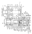
以下、図面に基づきながら本発明について説明する。図1は本発明に係る振動締固め機の側面図、図2は起振機の平断面図、図3は要部の斜視図(一部破断)、図4はリード角を有するスプラインの詳細説明図である。また、図5は位相変換機構の作用説明図であり、(a−1)は前進時における位相変換機構を示す平面説明図、(a−2)は(a−1)におけるA矢視図、(b−1)は後進時における位相変換機構を示す平面説明図、(b−2)は(b−1)におけるA矢視図である。
【0010】
図1において、振動締固め機(プレートコンパクタ)1は、起振機2,輾圧板3,原動機4を備え、後方部には操向用のハンドル5が取り付けられている。原動機4の出力軸に軸着されたプーリ6と起振機2の駆動軸12(図2)に軸着されたプーリ7との間にはベルト8が巻回されており、原動機4を始動させ、ベルト8を介して起振機2内の起振軸(駆動軸12,従動軸13)を回転させることにより輾圧板3に振動を与え、地盤を締め固める。なお、原動機4側に輾圧板3側の振動が直接伝達されないように、両者の間には防振ゴム51,51が取り付けられている。
【0011】
図2に示すように、起振機2は、ケース9とケース9の左右側部にそれぞれ取り付けられるカバー10,11を筐体とし、内部には起振軸である駆動軸12及び従動軸13が左右方向に沿って互いに平行となるように配設されている。駆動軸12は軸受14,14を介してケース9に回転自在に軸支されており、ケース9内においてその軸胴部には中空半月状の偏心錘16が固設されている。駆動軸12の一端側はカバー10から外部に突出し、その突出部には前記したようにプーリ7が軸着されている。一方、従動軸13は軸受15,15を介してケース9に回転自在に軸支されており、ケース9内においてその軸胴部には中空半月状の偏心錘17が固設されている。駆動軸12及び従動軸13は、カバー10内において、それぞれキー18,スプライン(リード角なし)19により軸着した駆動ギア20,従動ギア21が噛合することにより、互いに逆方向に同期回転するようになっている。従動ギア21はケース9及びカバー10に設けた軸受50,50により軸支されており、スプライン19は、従動軸13を構成する芯軸24がこの従動ギア21内を貫通して軸方向に移動可能とするためのものである。
【0012】
次に、前記偏心錘16,17の相互の位相を変える位相変換機構22について説明する。位相変換機構22は、一方の起振軸(従動軸13)を、偏心錘17が固設され、軸方向に関し移動不能に軸支される円筒軸23と、リード角を有するスプライン25により円筒軸23と螺合して円筒軸23内に収装され、ギア(駆動ギア20,従動ギア21)を介して他方の起振軸(駆動軸12)と同期回転可能に、且つ軸方向に関し移動可能に軸支される芯軸24と、から構成したものであり、芯軸24を軸方向に移動させることにより、円筒軸23及び偏心錘17を芯軸24に対し相対的に回動させる機構である。
【0013】
円筒軸23は、その中央の大径に形成された軸胴部23aの両端部において、軸受15,15の内輪15a,15aに挟まれて、軸方向に関し移動不能に軸支されており、軸胴部23aがケース9内に位置し、その外壁に偏心錘17が固設されている。また、軸胴部23aの内壁側においては、スプラインが螺旋状に形成されていて、リード角を有したスプラインとなっている(以降、円筒軸23側に形成されるスプラインをスプライン穴26、芯軸24側に形成されるスプラインをスプライン軸27といい、前記したスプライン25とは両者全体を指すものとする)。ここで、リード角とは、スプラインの歯のつる巻き線と、その上の1点を通る芯軸24(又は円筒軸23)に直角な平面とがなす角度をいい、図4に符号θにて示す。
【0014】
芯軸24は、スプライン軸27がスプライン穴26と螺合することにより円筒軸23内に同軸状に収装される。また、芯軸24の一端側には、前記したように従動ギア21を軸着するためのスプライン19が形成されている。したがって、仮に駆動ギア20,従動ギア21が無回転状態の場合を例にとると、芯軸24を軸方向に移動させた場合、スプライン19の存在により芯軸24は無回転のまま軸方向に移動し、一方、円筒軸23は、軸方向への移動が不能となっていることから、リード角を有したスプライン25の作用により回動することとなる。つまり、偏心錘17の位相が偏心錘16に対して変化することになる。勿論、原動機4が始動して駆動ギア20,従動ギア21が回転している場合であっても同様であり、芯軸24の軸方向の移動に対し、円筒軸23は芯軸24に対して相対的に回動することになる。
【0015】
このように、芯軸24の直線運動をスプライン25によって円筒軸23の回転運動に変換する構成とすれば、強度的に優れた位相変換機構を実現できる。すなわち、芯軸24と円筒軸23は互いにスプライン25の連続した歯面によって係合しあうことになり、換言すると面接触にて互いに連結されることとなり、したがって、高速回転による負荷や位相変換時にかかる負荷が分散され、歯の摩耗が生じにくくなる。よって、ガタの発生も小さくなり、長期使用の場合であっても安定した位相変換機能を維持することができ、また、ガタに起因する異音の発生も防止されることとなる。このように、本発明は、分解が非常に困難な起振機ケース(ケース9)の内部において、信頼性の高い、摩耗率、破損率に優れたリード角付きスプライン機構を構成させたものであり、修理面において非常に有効である。
【0016】
本例では、芯軸24の移動量(リード)に対する円筒軸23の回動角度を大きくする目的で、スプライン25を多条(本例では6条)スプラインとしてある。さらに同様の目的からスプライン25のリード角θ(図4)は15度〜45度の範囲にすることが望ましく、本例ではリード角θを25度としてある。このように、スプライン25を多条とし、またはリード角θを15度〜45度の範囲に設定することで、芯軸24の小さなストロークで円筒軸23を180度にわたって回動させることが可能となるため、機構部品の小型化、筐体の小型化を図ることができ、コンパクトな起振機とすることができる。
【0017】
また、スプライン穴26は、ブローチ盤研削により円筒軸23の内壁に直接加工することも可能であるが、スプライン穴を螺旋状に歯切りする加工は非常に手間のかかるものであり、正確な歯形状がでにくく、さらに加工中、切削屑が歯に食い込んで歯形がくずれてしまう等の問題がある。そこで、本例では、スプライン穴26を形成した円筒部材28を別途介在させた構成としてある。この円筒部材28は小型であることからロストワックス(精密鋳造)による成型が可能となり、したがって、そのスプライン穴26の歯形の精度も高いものとなっている。また、本例では、図4に示すように、円筒軸23(円筒部材28)側のスプライン、すなわちスプライン穴26において、基準ピッチp上における歯溝の幅寸法L1を歯厚寸法L2よりも大きくしてある。これにより、ロストワックスの型側においては、逆に山部の幅寸法が谷部の幅寸法よりも大きくなるため、肉厚な山部を確保することができる。したがって、型を回転させて抜く際には型の変形が小さくなり、また山部の型くずれを低減させることができる。なお、円筒部材28を円筒軸23内に固定させる場合、溶接では熱により両部材が変形してしまい、またボルト締結ではスプライン25における荷重作用によりボルトが緩んでしまう惧れがある。そこで、本例では、カッパーブレージング法により円筒部材28の外壁に固着させる態様としてある。
【0018】
次いで、前記芯軸24を軸方向に移動させるための芯軸移動機構30について説明する。前記円筒軸23は、その一端側がカバー11よりも外側に若干突出しており、その突出部を覆うように、円筒部31aを有する第1ボス部材31がその軸芯を芯軸24と同軸とし、フランジ部31bにてカバー11にボルト32(4ヵ所)で締結固定されている。円筒部31aには、相対向する筒壁部(本例では、筒壁部の上端及び下端)に一対の長孔31cが軸方向に沿って穿設されている。第1ボス部材31の円筒部31aの外側には、第2ボス部材33が回動可能に軸装されており、その円筒部33aには相対向する筒壁部において螺旋状に一対の長孔(以下、螺旋孔という)33bが穿設されている。符号61はスナップリングを示す。
【0019】
第2ボス部材33の円筒部33aの外側にはキャップ34が取り付けられており、第2ボス部材33とキャップ34はフランジ部33cにてボルト52(4ヵ所)により締結固定されている。キャップ34の外壁の一部は、カバー11から環状に立ち上がり成型されたガイド部11aの内壁にOリング35を介して回動可能に挿嵌している。キャップ34には、リング状を呈したアーム部材36がボルト37(4ヵ所)により締結固定されている。なお、アーム部材36は、一対のリング状の鋼板36a,36aの間に防振ゴム36bを介在させ、これらを接着して一体成型したものである。この防振ゴム36bの介在により、起振機2の振動はハンドル5に減衰されて伝わることになるため、ハンドル5を把持する作業者の疲労が軽減されることとなる。アーム部材36の鋼板36aの一部位は径方向側に突出してアーム部36cを形成しており、このアーム部36cに、レバー29の回動操作に連動するリンク機構38(図1参照、詳述せず)が接続している。
【0020】
符号39は、その一端側が、第1ボス部材31の円筒部31aの内側に摺動可能に挿嵌される摺動軸であり、他端側は円筒軸23内に挿通している。摺動軸39には、ピン40が摺動軸39の軸線と直交するように嵌め込まれている。また、このピン40の両端は摺動軸39の周面から共に突出しており、各突出部は第1ボス部材31の長孔31cを貫通して、第2ボス部材33の螺旋孔33b内に係合している。
【0021】
円筒軸23の内部において、摺動軸39の末端は小径となっており、この小径部には、軸受41を介して円筒状のベアリングケース42が取り付けられる。軸受41はボルト43,ワッシャ44,スプリングワッシャ45により摺動軸39に固定される。符号46は軸受41をベアリングケース42に固定するためのスナップリングを示す。ベアリングケース42は円筒軸23の内部において、軸方向に摺動可能且つ回動可能な部材である。そして、芯軸24の先端がこのベアリングケース42内に挿通しており、ピン47によりベアリングケース42に固定されている。なお、芯軸24の先端面には前記ボルト43用の逃げ穴48が穿設されている。
【0022】
以上の構成からなるプレートコンパクタ1の作用について説明する。原動機4からの回転力がベルト8を介して駆動軸12に伝えられると、駆動ギア20及び従動ギア21の介在により、芯軸24は駆動軸12と逆向きに同期回転し、スプライン25により芯軸24に螺合した円筒軸23とピン47により芯軸24に固定されたベアリングケース42も芯軸24と一体となって回転する(摺動軸39は軸受41の介在により回転しない)。図2はレバー29(図1)がニュートラル位置にある状態を示し、偏心錘16,17は上下方向のみの振動力を発生している。
【0023】
この状態からレバー29を前進側に回動操作すると、リンク機構38によりアーム部材36が図1における時計回りに所定角度回動し、前記ボルト52,37によって締結された第2ボス部材33とキャップ34も一体となって回動する。このとき、第2ボス部材33の螺旋孔33bに係合しているピン40は、この螺旋孔33bの内面の押力を受けることになるが、第1ボス部材31の長孔31cによって回動は阻止されるので、軸方向のベクトルだけが作用し、摺動軸39は図2における右側へと移動する(図5(a−1)の状態)。
【0024】
そして、軸受41,ベアリングケース42及びピン47を介して摺動軸39と連結した芯軸24も回転しながら同方向へ移動することになり、一方、円筒軸23は軸方向の移動が規制されていることから、スプライン25の作用により回動することになり、図5(a−2)に示すように偏心錘17の位相が偏心錘16の位相に対して90度変わることになる。
【0025】
また、後進させるときは、レバー29を後進側に回動操作すれば、リンク機構38によりアーム部材36が図1における反時計回りに所定角度回動し、第2ボス部材33の螺旋孔33bに係合しているピン40は、前進時とは逆向きに螺旋孔33bの内面からの押力を受けることになり、摺動軸39は図2における左側へと移動する(図5(b−1)の状態)。そして、芯軸24も回転を続けながら同方向へ移動することになり、一方、円筒軸23はスプライン25の作用により前進時とは逆向きに回動することになり、図5(b−2)に示すように偏心錘16に対する偏心錘17の位相は前進時とは逆位相となる。
【0026】
以上、本発明に係る振動締固め機についてその好適な実施形態を説明したが、構成部材の形状やそれらの配置構造などについては、図面に記載したものに限られることなく、本発明の主旨を逸脱しない範囲で設計変更が可能である。また、芯軸を移動させるための芯軸移動機構も上述した機構に限られることなく、本発明は実施可能となるものである。
【0027】
【発明の効果】
本発明に係る振動締固め機によれば、以下のような効果を奏する。
(1)芯軸の直線運動をリード角を有するスプラインによって円筒軸の回転運動に変換する構成とすれば、効率が良く、強度的に優れた位相変換機構を実現でき、安定した位相変換機能を維持することができる。
円筒軸側のスプラインにおいて、歯溝の幅寸法を歯厚寸法よりも大きくなるように構成すれば、スプラインをロストワックスにより成型する際、型の損傷を低減させることができる。
(2)スプラインのリード角を15度〜45度の範囲に設定することで、芯軸の小さなストロークで円筒軸を180度にわたって回動させることが可能となるため、機構部品の小型化、筐体の小型化を図ることができ、コンパクトな起振機とすることができる。
【図面の簡単な説明】
【図1】本発明に係る振動締固め機の側面図である。
【図2】起振機の平断面図である。
【図3】要部の斜視図(一部破断)である。
【図4】リード角を有するスプラインの詳細説明図である。
【図5】位相変換機構の作用説明図であり、(a−1)は前進時における位相変換機構を示す平面説明図、(a−2)は(a−1)におけるA矢視図、(b−1)は後進時における位相変換機構を示す平面説明図、(b−2)は(b−1)におけるA矢視図である。
【符号の説明】
1 プレートコンパクタ(振動締固め機)
2 起振機
3 輾圧板
4 原動機
9 ケース
12 駆動軸(起振軸)
13 従動軸(起振軸)
16,17 偏心錘
20 駆動ギア
21 従動ギア
22 位相変換機構
23 円筒軸
24 芯軸
25 スプライン
26 スプライン穴
27 スプライン軸
28 円筒部材
30 芯軸移動機構[0001]
BACKGROUND OF THE INVENTION
The present invention relates to a vibration type compacting machine used for compacting the ground in road construction and civil engineering work.
[0002]
[Prior art]
Usually, a vibration compactor includes a pair of parallel excitation shafts each having an eccentric weight, and the excitation shafts are synchronously rotated in opposite directions, and the direction of the excitation force generated by the rotation is vertical. By tilting it further, it is structured to move the aircraft forward or backward when jumping, and when the operator rotates the lever provided on the handle etc. to the forward side or the reverse side, The phase is converted over 180 degrees.
[0003]
An example of the phase conversion means of this eccentric weight is disclosed in Japanese Patent Publication No. 5-17323. This is because a gear boss having a spiral groove formed on the inner wall is attached to the outside of a cylindrical excitation shaft (driven shaft) having a long hole, and a rod having a pin is inserted inside the driven shaft. The pin is structured to engage with the elongated hole and the spiral groove, and the rod is moved in the axial direction (the pin moves while pressing the spiral groove) to rotate the driven shaft, The phase with respect to the eccentric weight of the excitation shaft (drive shaft) is changed.
[0004]
[Problems to be solved by the invention]
However, according to the phase conversion means, the rod and the driven shaft are connected to each other only by the engagement of the pins, that is, the structure is connected to each other by point contact. This load concentrates on this point contact engaging part, and as a result of long-term use, pins, long holes, and spiral holes wear and play, and accurate phase conversion cannot be performed, or at high speed rotation There was a possibility of making an abnormal noise or damaging the pin. In particular, the exciter case that supports the exciter shaft is extremely difficult to disassemble, and it has been a problem to apply such a member configuration that easily causes wear and damage to the inside of the exciter case.
[0005]
The present invention was created to solve such problems, and an object of the present invention is to provide a vibration compactor that can maintain a stable phase conversion function.
[0006]
[Means for Solving the Problems]
The present invention uses the following means in order to achieve the above object.
In a vibration compacting machine that includes a pair of excitation shafts each having an eccentric weight and moves the machine forward or backward by changing the mutual phase of the eccentric weights, one of the excitation shafts is provided with an eccentric weight, A cylindrical shaft that is supported so as not to move in the axial direction, and a spline having a lead angle, which is screwed into the cylindrical shaft and accommodated in the cylindrical shaft, and can be rotated synchronously with the other excitation shaft via a gear. And an axial weight fixed to the cylindrical shaft by moving the core shaft in the axial direction, and an eccentric weight fixed to the cylindrical shaft. By rotating relative to each other, the mutual phases of the eccentric weights are changed, and in the spline on the cylindrical shaft side, the width dimension of the tooth gap is made larger than the tooth thickness dimension .
[0007]
In addition, the lead angle of the spline was in the range of 15 degrees to 45 degrees.
[0009]
DETAILED DESCRIPTION OF THE INVENTION
The present invention will be described below with reference to the drawings. 1 is a side view of a vibration compactor according to the present invention, FIG. 2 is a plan sectional view of a vibration generator, FIG. 3 is a perspective view (partially broken) of an essential part, and FIG. 4 is a detail of a spline having a lead angle. It is explanatory drawing. FIG. 5 is an explanatory diagram of the operation of the phase conversion mechanism, (a-1) is an explanatory plan view showing the phase conversion mechanism at the time of forward movement, (a-2) is a view taken in the direction of arrow A in (a-1), (B-1) is a plane explanatory view showing a phase conversion mechanism during reverse travel, and (b-2) is a view taken in the direction of arrow A in (b-1).
[0010]
In FIG. 1, a vibration compactor (plate compactor) 1 includes an
[0011]
As shown in FIG. 2, the
[0012]
Next, the
[0013]
The
[0014]
The
[0015]
Thus, if it is set as the structure which converts the linear motion of the
[0016]
In this example, for the purpose of increasing the rotation angle of the
[0017]
The
[0018]
Next, the core shaft moving mechanism 30 for moving the
[0019]
A
[0020]
[0021]
Inside the
[0022]
The operation of the
[0023]
When the
[0024]
The
[0025]
When the
[0026]
The preferred embodiments of the vibration compactor according to the present invention have been described above. However, the shape of the constituent members and the arrangement structure thereof are not limited to those described in the drawings, and the gist of the present invention. Design changes can be made without departing from the scope. The core shaft moving mechanism for moving the core shaft is not limited to the above-described mechanism, and the present invention can be implemented.
[0027]
【The invention's effect】
The vibration compacting machine according to the present invention has the following effects.
(1) If the linear motion of the core shaft is converted into the rotational motion of the cylindrical shaft by a spline having a lead angle, an efficient and excellent phase conversion mechanism can be realized, and a stable phase conversion function can be realized. Can be maintained.
If the width of the tooth gap is configured to be larger than the tooth thickness in the spline on the cylindrical shaft side, damage to the mold can be reduced when the spline is molded with lost wax.
(2) By setting the lead angle of the spline within a range of 15 to 45 degrees, it becomes possible to rotate the cylindrical shaft over 180 degrees with a small stroke of the core shaft. The size of the body can be reduced, and a compact vibrator can be obtained.
[Brief description of the drawings]
FIG. 1 is a side view of a vibration compactor according to the present invention.
FIG. 2 is a plan sectional view of a vibrator.
FIG. 3 is a perspective view (partially broken) of a main part.
FIG. 4 is a detailed explanatory diagram of a spline having a lead angle.
FIGS. 5A and 5B are explanatory diagrams of the operation of the phase conversion mechanism, in which FIG. 5A is an explanatory plan view showing the phase conversion mechanism during forward movement, and FIG. b-1) is an explanatory plan view showing the phase conversion mechanism during reverse travel, and (b-2) is a view taken in the direction of arrow A in (b-1).
[Explanation of symbols]
1 Plate compactor (vibration compaction machine)
2 Exciter 3
13 Driven shaft (vibration shaft)
16, 17
Claims (2)
一方の起振軸を、偏心錘が固設され、軸方向に関し移動不能に軸支される円筒軸と、リード角を有するスプラインにより前記円筒軸と螺合して前記円筒軸内に収装され、ギアを介して他方の起振軸と同期回転可能に、且つ軸方向に関し移動可能に軸支される芯軸と、から構成し、
前記芯軸を軸方向に移動させて、前記円筒軸及び前記円筒軸に固設された偏心錘を前記芯軸に対し相対的に回動させることにより、偏心錘の相互の位相を変える構成とし、
前記円筒軸側のスプラインにおいて、歯溝の幅寸法を歯厚寸法よりも大きくしたことを特徴とする振動締固め機。In a vibration compacting machine comprising a pair of excitation shafts each having an eccentric weight and moving the machine forward or backward by changing the mutual phase of the eccentric weights,
One vibration shaft is fitted in the cylindrical shaft by being screwed to the cylindrical shaft by a spline having a lead angle and a cylindrical shaft that is fixedly mounted with an eccentric weight and is not movable in the axial direction. A core shaft that is pivotally supported so as to be able to rotate synchronously with the other excitation shaft via a gear and to be movable in the axial direction,
By moving the core shaft in the axial direction and rotating the cylindrical shaft and the eccentric weight fixed to the cylindrical shaft relative to the core shaft, the mutual phases of the eccentric weights are changed. ,
In the spline on the cylindrical shaft side, the vibration compaction machine is characterized in that the width dimension of the tooth gap is made larger than the tooth thickness dimension .
Priority Applications (1)
| Application Number | Priority Date | Filing Date | Title |
|---|---|---|---|
| JP19903999A JP4242012B2 (en) | 1999-07-13 | 1999-07-13 | Vibration compaction machine |
Applications Claiming Priority (1)
| Application Number | Priority Date | Filing Date | Title |
|---|---|---|---|
| JP19903999A JP4242012B2 (en) | 1999-07-13 | 1999-07-13 | Vibration compaction machine |
Publications (2)
| Publication Number | Publication Date |
|---|---|
| JP2001026905A JP2001026905A (en) | 2001-01-30 |
| JP4242012B2 true JP4242012B2 (en) | 2009-03-18 |
Family
ID=16401111
Family Applications (1)
| Application Number | Title | Priority Date | Filing Date |
|---|---|---|---|
| JP19903999A Expired - Fee Related JP4242012B2 (en) | 1999-07-13 | 1999-07-13 | Vibration compaction machine |
Country Status (1)
| Country | Link |
|---|---|
| JP (1) | JP4242012B2 (en) |
Families Citing this family (1)
| Publication number | Priority date | Publication date | Assignee | Title |
|---|---|---|---|---|
| DE102020110952A1 (en) * | 2020-04-22 | 2021-10-28 | Hamm Ag | Imbalance arrangement for a compactor roller of a soil compactor |
-
1999
- 1999-07-13 JP JP19903999A patent/JP4242012B2/en not_active Expired - Fee Related
Also Published As
| Publication number | Publication date |
|---|---|
| JP2001026905A (en) | 2001-01-30 |
Similar Documents
| Publication | Publication Date | Title |
|---|---|---|
| KR100366693B1 (en) | Gear transmission | |
| JP3331216B2 (en) | Improved cutting tool | |
| EP1225117B1 (en) | An electric power steering system | |
| KR102636416B1 (en) | Steering apparatus | |
| WO2008128804A1 (en) | Motor-driven machine tool | |
| JP2022131351A (en) | power transmission unit | |
| JP7686464B2 (en) | Construction Machinery | |
| JP4242012B2 (en) | Vibration compaction machine | |
| WO2019146298A1 (en) | Compactor | |
| JP3510208B2 (en) | Crank transmission | |
| CN101096984B (en) | Brake band holder | |
| US5010717A (en) | Oscillating-type mowing apparatus | |
| JP7670554B2 (en) | Drive transmission device | |
| JP5214357B2 (en) | Reciprocating work tool | |
| JP2966382B2 (en) | Hand-held working device with drive motor | |
| JP7185472B2 (en) | Electric tool | |
| JP3734679B2 (en) | Reciprocating cutting tool | |
| JP2001200912A (en) | Worm gear device | |
| JPH089209Y2 (en) | Plate compactor exciter structure | |
| JP4743666B2 (en) | Electric tool | |
| KR101931282B1 (en) | The saw device | |
| JP2002079416A (en) | Portable electric cutting machine | |
| JPH0513142Y2 (en) | ||
| JP3734680B2 (en) | Reciprocating cutting tool | |
| JPH01180799A (en) | Press machine equipped with stroke adjusting device |
Legal Events
| Date | Code | Title | Description |
|---|---|---|---|
| A621 | Written request for application examination |
Free format text: JAPANESE INTERMEDIATE CODE: A621 Effective date: 20060613 |
|
| A977 | Report on retrieval |
Free format text: JAPANESE INTERMEDIATE CODE: A971007 Effective date: 20080514 |
|
| A131 | Notification of reasons for refusal |
Free format text: JAPANESE INTERMEDIATE CODE: A131 Effective date: 20080520 |
|
| A521 | Written amendment |
Free format text: JAPANESE INTERMEDIATE CODE: A523 Effective date: 20080703 |
|
| TRDD | Decision of grant or rejection written | ||
| A01 | Written decision to grant a patent or to grant a registration (utility model) |
Free format text: JAPANESE INTERMEDIATE CODE: A01 Effective date: 20081216 |
|
| A01 | Written decision to grant a patent or to grant a registration (utility model) |
Free format text: JAPANESE INTERMEDIATE CODE: A01 |
|
| A61 | First payment of annual fees (during grant procedure) |
Free format text: JAPANESE INTERMEDIATE CODE: A61 Effective date: 20081224 |
|
| FPAY | Renewal fee payment (event date is renewal date of database) |
Free format text: PAYMENT UNTIL: 20120109 Year of fee payment: 3 |
|
| R150 | Certificate of patent or registration of utility model |
Ref document number: 4242012 Country of ref document: JP Free format text: JAPANESE INTERMEDIATE CODE: R150 Free format text: JAPANESE INTERMEDIATE CODE: R150 |
|
| FPAY | Renewal fee payment (event date is renewal date of database) |
Free format text: PAYMENT UNTIL: 20150109 Year of fee payment: 6 |
|
| R250 | Receipt of annual fees |
Free format text: JAPANESE INTERMEDIATE CODE: R250 |
|
| R250 | Receipt of annual fees |
Free format text: JAPANESE INTERMEDIATE CODE: R250 |
|
| R250 | Receipt of annual fees |
Free format text: JAPANESE INTERMEDIATE CODE: R250 |
|
| LAPS | Cancellation because of no payment of annual fees |