JP4240325B2 - Control device - Google Patents
Control device Download PDFInfo
- Publication number
- JP4240325B2 JP4240325B2 JP2006077638A JP2006077638A JP4240325B2 JP 4240325 B2 JP4240325 B2 JP 4240325B2 JP 2006077638 A JP2006077638 A JP 2006077638A JP 2006077638 A JP2006077638 A JP 2006077638A JP 4240325 B2 JP4240325 B2 JP 4240325B2
- Authority
- JP
- Japan
- Prior art keywords
- value
- air
- fuel ratio
- control
- output
- Prior art date
- Legal status (The legal status is an assumption and is not a legal conclusion. Google has not performed a legal analysis and makes no representation as to the accuracy of the status listed.)
- Expired - Fee Related
Links
Images


Description
本発明は、制御対象への制御入力をΔΣ変調アルゴリズムなどに基づいて算出することにより、制御対象の出力を目標値に収束させるように制御する制御装置に関する。 The present invention relates to a control apparatus that controls a control input to be converged to a target value by calculating a control input to the control target based on a ΔΣ modulation algorithm or the like.
従来、この種の制御装置として、例えば特許文献1に記載されたものが知られている。この制御装置は、制御対象の出力を検出し、その検出結果をアナログ量の検出信号として出力する検出手段と、上位装置から入力されるアナログ量の目標値と検出信号との偏差を演算する偏差演算手段と、演算された偏差を1ビットデジタル信号に変換する変換手段と、変換手段からの1ビットデジタル信号を補償し、操作信号として出力する補償手段とを備えている(同公報の図6参照)。
Conventionally, as this type of control device, for example, one described in
この制御装置では、偏差演算手段により、検出信号と目標値との偏差(アナログ量)が演算され、この演算偏差は、変換手段でのΔΣ変調によって1ビットデジタル信号に変換され、さらに補償手段により補償された後、操作信号として制御対象に入力される。以上の構成により、制御対象の出力と目標値との偏差を打
ち消すように、偏差と逆位相の操作量が生成され、制御対象に入力される。その結果、制御対象の出力が目標値に収束するようにフィードバック制御される。
In this control device, the deviation (analog amount) between the detection signal and the target value is calculated by the deviation calculating means, and this calculated deviation is converted into a 1-bit digital signal by ΔΣ modulation by the converting means, and further by the compensating means. After being compensated, it is input to the control object as an operation signal. With the above configuration, an operation amount having a phase opposite to the deviation is generated and input to the control target so as to cancel the deviation between the output of the control target and the target value. As a result, feedback control is performed so that the output of the controlled object converges to the target value.
上記従来の制御装置によれば、制御対象の動特性が比較的大きな位相遅れやむだ時間などを有している場合、それに起因して、制御対象への入力信号の入力後、入力信号を反映する出力信号が制御対象から出力されるまでに時間がかかり、制御対象の入出力間での制御タイミングのずれを生じる。その結果、制御系が不安定になってしまうおそれがある。例えば、内燃機関の燃料噴射量を入力として、内燃機関の排気ガスの空燃比を制御する場合、燃料噴射が実際に行われてから、排気ガスの空燃比の状態が実際に変化するまでに時間を要するため、空燃比制御の安定性および制御性が低下し、触媒で浄化された排気ガスの特性が不安定な状態になってしまうことがある。 According to the above conventional control device, when the dynamic characteristic of the control target has a relatively large phase delay or dead time, the input signal is reflected after the input signal is input to the control target. It takes time until the output signal to be output from the control target, and a control timing shift occurs between the input and output of the control target. As a result, the control system may become unstable. For example, when the air-fuel ratio of the exhaust gas of the internal combustion engine is controlled using the fuel injection amount of the internal combustion engine as an input, it takes time from the actual fuel injection to the actual change of the air-fuel ratio of the exhaust gas. Therefore, the stability and controllability of the air-fuel ratio control is lowered, and the characteristics of the exhaust gas purified by the catalyst may become unstable.
本発明は、上記課題を解決するためになされたもので、制御対象が位相遅れやむだ時間などが比較的大きい動特性を示す場合でも、制御対象の入出力間での制御タイミングのずれを解消することができ、それにより、制御の安定性および制御性を向上させることができる制御装置を提供することを目的とする。 The present invention has been made to solve the above problem, and even when the controlled object exhibits a relatively large dynamic characteristic such as a phase delay or a dead time, the control timing deviation between the input and output of the controlled object is eliminated. It is an object of the present invention to provide a control device that can improve control stability and controllability.
この目的を達成するために、請求項1に係る制御装置1は、予測アルゴリズム(式(6),(7))に基づき、制御対象の出力(酸素濃度センサ15の出力Vout)と所定の目標値Vopとの偏差である出力偏差VO2の予測値PREVO2を算出する予測値算出手段(ECU2、状態予測器22、ステップ33)と、算出された出力偏差の予測値PREVO2に補正係数(ゲインKRDSM,G d )を乗算する乗算手段(ECU2、ステップ195)と、補正係数を、出力偏差の予測値が所定値(値0)以上のときに、所定値未満のときよりも小さい値に設定する補正係数設定手段(ECU2、ステップ192〜194)と、Δ変調アルゴリズム、ΔΣ変調アルゴリズムおよびΣΔ変調アルゴリズムのうちのいずれか1つの変調アルゴリズムに基づき、補正係数(ゲインKRDSM,G d )が乗算された出力偏差の予測値PREVO2に応じて、制御対象の出力を所定の目標値Vopに収束するように制御するための、制御対象への制御入力(目標空燃比KCMD)を算出する制御入力算出手段(ECU2、ADSMコントローラ20、ステップ38)と、を備えることを特徴とする。
In order to achieve this object, the
この制御装置によれば、予測アルゴリズムに基づき、制御対象の出力と所定の目標値との偏差である出力偏差の予測値が算出され、Δ変調アルゴリズム、ΔΣ変調アルゴリズムおよびΣΔ変調アルゴリズムのうちのいずれか1つの変調アルゴリズムに基づき、補正係数を乗算した出力偏差の予測値に応じて、制御入力が算出されるので、このような予測値を、例えば制御対象の位相遅れやむだ時間などの動特性を反映させた値として算出することにより、制御対象の入出力間での制御タイミングのずれを解消することが可能になる。さらに、制御対象の出力を所定の目標値に収束するように制御するための制御入力が、補正係数を乗算した出力偏差の予測値に応じて算出されるとともに、この補正係数が、出力偏差の予測値が所定値以上のときに、所定値未満のときよりも小さい値に設定されるので、出力偏差の予測値の所定値に対する大小関係に応じて、制御対象の出力を目標値に収束させる収束速度を変更することができる。その結果、制御の安定性の確保および制御性の向上が可能になる(なお、本明細書における、「予測値の算出」および「制御入力の算出」などの「算出」は、プログラムにより演算することに限らず、ハードウエアによりそれらを表す電気信号を生成することを含む)。 According to this control device, based on the prediction algorithm, the predicted value of the output deviation, which is the deviation between the output of the controlled object and the predetermined target value, is calculated, and any one of the Δ modulation algorithm, the ΔΣ modulation algorithm, and the ΣΔ modulation algorithm Since the control input is calculated according to the predicted value of the output deviation multiplied by the correction coefficient based on the one modulation algorithm, such a predicted value is used as a dynamic characteristic such as a phase delay or a dead time of the control target. By calculating as a value reflecting the above, it is possible to eliminate a shift in control timing between the input and output of the control target. Further, a control input for controlling the output to be controlled to converge to a predetermined target value is calculated according to the predicted value of the output deviation multiplied by the correction coefficient, and this correction coefficient is calculated based on the output deviation. When the predicted value is equal to or greater than the predetermined value, the value is set to be smaller than when the predicted value is less than the predetermined value. Therefore, the output of the control target is converged to the target value according to the magnitude relationship of the predicted value of the output deviation with respect to the predetermined value. The convergence speed can be changed. As a result, control stability can be ensured and controllability can be improved (in this specification, “calculation” such as “calculation of predicted value” and “calculation of control input” is calculated by a program. Including, but not limited to, generating electrical signals representing them by hardware).
請求項2に係る発明は、請求項1に記載の制御装置1において、予測値算出手段は、予測アルゴリズムに基づき、算出された制御入力(目標空燃比KCMD)と制御対象に入力された制御入力を反映する値(LAFセンサ14の出力KACT)との少なくとも一方、および制御対象の出力(酸素濃度センサ15の出力Vout)に応じて、出力偏差の予測値PREVO2を算出することを特徴とする。
According to a second aspect of the present invention, in the
この制御装置によれば、出力偏差の予測値を、制御入力の状態を反映させながら算出することができ、その分、出力偏差の予測値の算出精度(予測精度)を高めることができる。その結果、制御の安定性を確保でき、制御性を向上させることができる。 According to this control device, the predicted value of the output deviation can be calculated while reflecting the state of the control input, and the calculation accuracy (prediction accuracy) of the predicted value of the output deviation can be increased accordingly. As a result, control stability can be ensured and controllability can be improved.
請求項3に係る発明は、請求項1または2に記載の制御装置1において、予測アルゴリズムは、制御入力と制御対象に入力された制御入力を反映する値との一方を表す値(空燃比偏差DKCMD、LAF出力偏差DKACT)と、出力偏差VO2とを変数とする制御対象モデル(式(1))に基づくアルゴリズムであることを特徴とする。
According to a third aspect of the present invention, in the
この制御装置によれば、制御入力または制御入力を反映する値との一方を表す値と、出力偏差とを変数とする制御対象モデルに基づいて、予測値が算出されるので、この制御対象モデルを、制御対象の位相遅れやむだ時間などの動特性を反映させたものとして定義することにより、出力偏差の予測値を、制御対象の位相遅れやむだ時間などの動特性を反映させた値として算出することができる。また、一般に、制御対象モデルでは、制御対象の入出力と所定値との偏差を、入出力を表す変数として定義した場合の方が、入出力の絶対値を変数として定義した場合よりも、モデルパラメータをより正確に同定または定義できることで、制御対象モデルの動特性を制御対象の実際の動特性に適合させることができるという事実が知られている。したがって、この制御装置によれば、制御対象モデルが、制御対象の出力と所定の目標値との偏差である出力偏差を変数としているので、制御対象の出力の絶対値を変数とする場合と比べて、制御対象の実際の動特性に対する制御対象モデルの動特性の適合性を向上させることができ、それにより、出力偏差の予測値の算出精度をさらに高めることができる。その結果、制御の安定性を確保することができ、制御性を向上させることができる。 According to this control apparatus, since the predicted value is calculated based on the control target model using the value representing one of the control input or the value reflecting the control input and the output deviation as a variable, the control target model Is defined as a value that reflects the dynamic characteristics such as the phase delay and dead time of the controlled object, so that the predicted output deviation is a value that reflects the dynamic characteristics such as the phase delay and dead time of the controlled object. Can be calculated. In general, in the control target model, the deviation between the input / output of the control target and the specified value is defined as a variable that represents the input / output rather than the absolute value of the input / output defined as a variable. It is known that the parameters can be more accurately identified or defined so that the dynamic characteristics of the controlled object model can be adapted to the actual dynamic characteristics of the controlled object. Therefore, according to this control apparatus, since the control target model uses the output deviation, which is the deviation between the output of the control target and the predetermined target value, as a variable, compared with the case where the absolute value of the output of the control target is a variable. Thus, it is possible to improve the adaptability of the dynamic characteristic of the controlled object model to the actual dynamic characteristic of the controlled object, thereby further increasing the calculation accuracy of the predicted value of the output deviation. As a result, control stability can be ensured and controllability can be improved.
請求項4に係る発明は、請求項3に記載の制御装置1において、制御入力と制御対象に入力された制御入力を反映する値との一方を表す値は、制御入力(目標空燃比KCMD)と所定の基準値FLAFBASEとの偏差(空燃比偏差DKCMD)、および制御対象に入力された制御入力を反映する値(LAFセンサ14の出力KACT)と所定の基準値FLAFBASEとの偏差(LAF出力偏差DKACT)の一方であることを特徴とする。
According to a fourth aspect of the present invention, in the
前述したように、制御対象モデルでは、制御対象の入出力と所定値との偏差を、入出力を表す変数として定義した場合の方が、入出力の絶対値を変数として定義した場合よりも、制御対象モデルの動特性を制御対象の実際の動特性に適合させることができる。したがって、この制御装置によれば、制御対象モデルが、算出された制御入力と所定の基準値との偏差、または制御対象に入力された制御入力を反映する値と所定の基準値との偏差を変数としているので、制御入力または制御入力を反映する値の絶対値を変数とする場合と比べて、制御対象の実際の動特性に対する制御対象モデルの動特性の適合性を向上させることができ、それにより、予測値の算出精度をより一層、高めることができる。 As described above, in the control target model, the deviation between the input / output of the control target and the predetermined value is defined as a variable representing the input / output, rather than the absolute value of the input / output defined as a variable. The dynamic characteristics of the controlled object model can be adapted to the actual dynamic characteristics of the controlled object. Therefore, according to this control apparatus, the controlled object model calculates the deviation between the calculated control input and the predetermined reference value, or the difference between the value reflecting the control input input to the controlled object and the predetermined reference value. Since it is a variable, compared with the case where the absolute value of the control input or the value that reflects the control input is a variable, the suitability of the controlled model's dynamic characteristics to the actual dynamic characteristics of the controlled object can be improved, Thereby, the calculation accuracy of the predicted value can be further increased.
請求項5に係る発明は、請求項1ないし4のいずれかに記載の制御装置1において、制御入力算出手段は、1つの変調アルゴリズムに基づき、補正係数(ゲインKRDSM,G d )が乗算された出力偏差の予測値PREVO2に応じて中間値(DSM信号値DSMSGNS)を算出するとともに、算出された中間値に所定のゲイン(KDSM)を乗算した値に基づき、制御入力(目標空燃比KCMD、適応目標空燃比KCMDSLD)を算出することを特徴とする。
According to a fifth aspect of the present invention, in the
一般に、ΔΣ変調アルゴリズム、ΣΔ変調アルゴリズムおよびΔ変調アルゴリズムの各々は、制御対象のゲインが値1であるとして制御入力を決定するものであるので、制御対象の実際のゲインが値1と異なる場合には、制御入力が適切な値に算出されなくなることで、制御性が低下することがある。例えば、制御対象の実際のゲインが値1よりも大きい場合には、制御入力が必要以上に大きい値として算出されるため、オーバーゲインの状態になってしまうおそれがある。これに対して、この制御装置によれば、制御入力が、1つの変調アルゴリズムに基づいて算出された中間値に所定のゲインを乗算した値に基づいて、算出されるので、この所定のゲインを適切に設定することにより、良好な制御性を確保することができる。
In general, each of the ΔΣ modulation algorithm, the ΣΔ modulation algorithm, and the Δ modulation algorithm determines the control input on the assumption that the gain to be controlled is 1, so that the actual gain to be controlled is different from the
請求項6に係る発明は、請求項5に記載の制御装置1において、制御対象のゲイン特性を表すゲインパラメータ(排気ガスボリュームAB_SV)を検出するゲインパラメータ検出手段(ECU2、吸気管内絶対圧センサ11、クランク角センサ13、ステップ80)と、検出されたゲインパラメータに応じて、所定のゲインの値(KDSM)を設定するゲイン設定手段(ECU2、ステップ200)と、をさらに備えることを特徴とする。
According to a sixth aspect of the present invention, in the
この制御装置によれば、制御入力の算出に用いる所定のゲインが、制御対象のゲイン特性に応じて設定されるので、制御入力を制御対象のゲイン特性に応じた適切なエネルギを有する値として算出でき、それにより、オーバーゲイン状態の発生などを回避でき、良好な制御性を確保できる。 According to this control device, since the predetermined gain used for calculating the control input is set according to the gain characteristic of the control target, the control input is calculated as a value having appropriate energy according to the gain characteristic of the control target. Thus, the occurrence of an overgain state or the like can be avoided, and good controllability can be ensured.
請求項7に係る発明は、請求項1ないし6のいずれかに記載の制御装置1において、制御入力算出手段は、1つの変調アルゴリズムに基づき、補正係数(ゲインKRDSM,G d )が乗算された出力偏差の予測値PREVO2に応じて第2の中間値(ΔΣ変調制御量DKCMDDSM)を算出するとともに(ステップ201)、算出された第2の中間値に所定値(基準値FLAFBASE)を加算することにより、制御入力(適応目標空燃比KCMDSLD)を算出する(ステップ211)ことを特徴とする。
According to a seventh aspect of the present invention, in the
一般に、Δ変調アルゴリズム、ΔΣ変調アルゴリズムおよびΣΔ変調アルゴリズムはいずれも、値0を中心とした正負反転型の制御入力しか算出できない。これに対して、この制御装置によれば、制御入力算出手段により、制御入力の算出が、1つの変調アルゴリズムに基づいて算出された第2の中間値に所定値を加算することにより行われるので、制御入力を、値0を中心として正負反転する値だけでなく、所定値を中心として所定幅の増減を繰り返す値として算出することができ、制御の自由度を高めることができる。
In general, any of the Δ modulation algorithm, the ΔΣ modulation algorithm, and the ΣΔ modulation algorithm can only calculate a positive / negative inversion type control input centered on a value of 0. On the other hand, according to this control apparatus, the control input calculation unit calculates the control input by adding a predetermined value to the second intermediate value calculated based on one modulation algorithm. The control input can be calculated not only as a value that reverses positive and negative around the
請求項8に係る発明は、請求項1ないし7のいずれかに記載の制御装置1において、予測値算出手段は、制御入力(目標空燃比KCMD)が制御対象に入力されてから制御対象の出力(酸素濃度センサ15の出力Vout)に反映されるまでの予測時間dtを、制御対象の動特性(排気ガスボリュームAB_SV)に応じて算出するとともに(ステップ81)、算出された予測時間dtに応じて、出力偏差の予測値PREVO2を算出する(ステップ33)ことを特徴とする。
According to an eighth aspect of the present invention, in the
この制御装置によれば、制御入力が制御対象に入力されてから制御対象の出力に反映されるまでの予測時間が、制御対象の動特性に応じて算出されるとともに、算出された予測時間に応じて、出力偏差の予測値が算出されるので、このように算出された出力偏差の予測値を用いて制御入力を算出することにより、制御対象の応答遅れやむだ時間などに起因する、制御対象の入出力間での制御タイミングのずれを、より確実に解消することができ、制御性をより一層、向上させることができる。 According to this control device, the predicted time from when the control input is input to the controlled object until it is reflected in the output of the controlled object is calculated according to the dynamic characteristics of the controlled object, and the calculated predicted time is Accordingly, the predicted value of the output deviation is calculated accordingly, and by calculating the control input using the predicted value of the output deviation calculated in this way, the control caused by the response delay or dead time of the controlled object A shift in control timing between the input and output of the target can be eliminated more reliably, and the controllability can be further improved.
請求項9に係る発明は、請求項2に記載の制御装置1において、制御対象の出力は、内燃機関3の排気通路(排気管7)の触媒(第1触媒装置8a)よりも下流側に配置され、触媒を通過した後の排気ガスの空燃比を検出する下流側空燃比センサ(酸素濃度センサ15)の出力Voutであり、制御対象への制御入力は、内燃機関3に供給される混合気の目標空燃比KCMDであり、制御対象に入力された制御入力を反映する値は、排気通路の触媒(第1触媒装置8a)よりも上流側に配置され、触媒を通過する前の排気ガスの空燃比を検出する上流側空燃比センサ(LAFセンサ14)の出力KACTであり、予測値算出手段は、予測アルゴリズム(式(7))に基づき、内燃機関に供給された混合気の目標空燃比KCMDおよび上流側空燃比センサの出力KACTの少なくとも一方と、下流側空燃比センサの出力Voutとに応じて、出力偏差VO2の予測値PREVO2を算出し、制御入力算出手段は、1つの変調アルゴリズムに基づき、補正係数(ゲインKRDSM,G d )が乗算された出力偏差の予測値に応じて、下流側空燃比センサの出力Voutを所定の目標値Vopに収束させるための、内燃機関に供給すべき混合気の目標空燃比KCMDを算出する空燃比算出手段(ECU2、ステップ38)で構成されていることを特徴とする。
According to a ninth aspect of the present invention, in the
この制御装置によれば、下流側空燃比センサの出力と所定の目標値との偏差である出力偏差の予測値が、内燃機関に供給された混合気の目標空燃比および/または上流側空燃比センサの出力と、下流側空燃比センサの出力とに応じて算出され、下流側空燃比センサの出力を所定の目標値に収束させるための混合気の目標空燃比が、補正係数が乗算された出力偏差の予測値に応じて、1つの変調アルゴリズムに基づき、算出される。制御入力すなわち混合気の目標空燃比が以上のように算出されるので、所定の目標値を適切に設定することにより、排気ガスの空燃比を、触媒による排気ガスの浄化状態が良好な状態になるように制御することができ、その結果、触媒で浄化された排気ガスの特性(以下「触媒後排気ガス特性」という)を向上させることができる。また、予測値が、触媒よりも上に設けた上流側空燃比センサの出力に応じて算出されるので、触媒に実際に供給される排気ガスの空燃比の状態を予測値により適切に反映させることができ、その分、予測値の算出精度を向上させることができる。さらに、出力偏差の予測値に乗算される補正係数が、出力偏差の予測値が所定値以上のときに、所定値未満のときよりも小さい値に設定されるので、出力偏差の予測値の所定値に対する大小関係に応じて、下流側空燃比センサの出力を所定の目標値に収束させる収束速度を変更することができる。したがって、例えばこの所定値を値0に設定した場合、出力偏差の予測値が値0以上のとき、すなわち下流側空燃比センサの出力が目標値よりも大きいことで、目標空燃比をリーン側に変更すべきときには、リッチ側に変更するときよりも収束速度が小さく設定されることにより、リーンバイアスによるNOx排出量の抑制効果を得ることができる。一方、目標空燃比をリッチ側に変更すべきときには、リーン側に変更するときよりも収束速度が大きい値に設定されることにより、触媒のNOx浄化率を十分に回復させることができる。
According to this control device, the predicted value of the output deviation, which is the deviation between the output of the downstream air-fuel ratio sensor and the predetermined target value , is the target air-fuel ratio and / or upstream air-fuel ratio of the air-fuel mixture supplied to the internal combustion engine. the output of the sensor is calculated in accordance with the output of the downstream air-fuel ratio sensor, the target air-fuel ratio of the mixture for converging the output of the downstream air-fuel ratio sensor to a predetermined target value, the correction coefficient is multiplied It is calculated based on one modulation algorithm according to the predicted value of the output deviation. Since the control input, that is, the target air-fuel ratio of the air-fuel mixture is calculated as described above, by appropriately setting a predetermined target value, the exhaust gas air-fuel ratio can be changed to a state in which the exhaust gas purification state by the catalyst is good. As a result, the characteristics of the exhaust gas purified by the catalyst (hereinafter referred to as “post-catalyst exhaust gas characteristics”) can be improved. Further, since the predicted value is calculated according to the output of the upstream air-fuel ratio sensor provided above the catalyst, the state of the air-fuel ratio of the exhaust gas actually supplied to the catalyst is appropriately reflected by the predicted value. Therefore, the calculation accuracy of the predicted value can be improved accordingly. Further, since the correction coefficient to be multiplied by the predicted value of output deviation is set to a smaller value when the predicted value of output deviation is greater than or equal to a predetermined value, it is set to a predetermined value of the predicted value of output deviation. The convergence speed for converging the output of the downstream air-fuel ratio sensor to a predetermined target value can be changed according to the magnitude relationship with respect to the value. Therefore, for example, when this predetermined value is set to the
請求項10に係る発明は、請求項9に記載の制御装置1において、内燃機関の運転状態(エンジン回転数NE、吸気管内絶対圧PBA)を検出する運転状態検出手段(ECU2、吸気管内絶対圧センサ11、クランク角センサ13)をさらに備え、予測値算出手段は、検出された内燃機関の運転状態に応じて、目標空燃比の混合気が内燃機関に供給されてから下流側空燃比センサの出力に反映されるまでの予測時間dtを算出するとともに、算出された予測時間dtにさらに応じて、出力偏差VO2の予測値PREVO2を算出することを特徴とする。
According to a tenth aspect of the present invention, in the
この種の空燃比を制御する制御装置では、内燃機関および触媒を含めた制御対象の動特性(例えば応答遅れやむだ時間)は、内燃機関の運転状態、例えば排気ガスボリュームに応じて変化する。これに対して、この制御装置によれば、目標空燃比の混合気が内燃機関に供給されてから下流側空燃比センサの出力に反映されるまでの予測時間が、運転状態に応じて算出されるとともに、この算出された予測時間にさらに応じて、出力偏差の予測値が算出されるので、このように算出された予測値を用いて制御入力を算出することにより、制御対象の動特性に起因する、制御対象の入出力間での制御タイミングのずれを、より確実に解消することができ、触媒後排気ガス特性をより一層、向上させることができる。 In this type of control device that controls the air-fuel ratio, the dynamic characteristics (for example, response delay and dead time) of the controlled objects including the internal combustion engine and the catalyst vary according to the operating state of the internal combustion engine, for example, the exhaust gas volume. On the other hand, according to this control device, the predicted time from when the air-fuel mixture having the target air-fuel ratio is supplied to the internal combustion engine until it is reflected in the output of the downstream air-fuel ratio sensor is calculated according to the operating state. In addition, since the predicted value of the output deviation is calculated further in accordance with the calculated predicted time, the control input is calculated using the predicted value calculated in this way, so that the dynamic characteristics of the controlled object can be obtained. The resulting shift in the control timing between the input and output of the control target can be eliminated more reliably, and the post-catalyst exhaust gas characteristics can be further improved.
請求項11に係る発明は、請求項9に記載の制御装置1において、内燃機関の運転状態を検出する運転状態検出手段をさらに備え、空燃比算出手段は、1つの変調アルゴリズムに基づき、補正係数(ゲインKRDSM,G d )が乗算された出力偏差の予測値PREVO2に応じて、内燃機関に供給すべき混合気の目標空燃比の中間値(DSM信号値DSMSGNS)を算出する中間値算出手段(ECU2、ステップ195〜199)と、検出された内燃機関の運転状態に応じて、ゲイン(KDSM)を設定するゲイン設定手段(ECU2、ステップ200)と、算出された中間値に設定されたゲインを乗算した値に基づいて、内燃機関に供給すべき混合気の目標空燃比KCMD(適応目標空燃比KCMDSLD)を算出する目標空燃比算出手段(ECU2、ステップ211)と、を備えることを特徴とする。
The invention according to
この種の空燃比を制御する制御装置では、内燃機関および触媒を含めた制御対象の空燃比に対するゲイン特性は、内燃機関の運転状態、例えば排気ガスボリュームに応じて変化する。この場合、1つの変調アルゴリズムは、前述したように、制御対象のゲインが値1であるとして制御入力を決定するものであるので、制御対象のゲイン特性が上記のように変化すると、制御入力としての混合気の目標空燃比が適切な値から大きく離れた振動的なものとなり、触媒よりも下流側の下流側空燃比センサの出力も振動的なものとなる。その結果、触媒後排気ガス特性が悪化してしまう。これに対して、この制御装置によれば、混合気の目標空燃比が、1つの変調アルゴリズムに基づいて算出された中間値にゲインを乗算した値に基づいて、算出されるとともに、このゲインが運転状態に応じて設定されるので、混合気の目標空燃比を、運転状態の変化に伴う、制御対象のゲイン特性の変化を適切に反映した値として算出でき、それにより、触媒後排気ガス特性をさらに向上させることができる。 In this type of control device that controls the air-fuel ratio, the gain characteristic with respect to the air-fuel ratio of the control target including the internal combustion engine and the catalyst changes according to the operating state of the internal combustion engine, for example, the exhaust gas volume. In this case, as described above, since one modulation algorithm determines the control input on the assumption that the gain to be controlled is a value of 1, if the gain characteristic of the control target changes as described above, The target air-fuel ratio of the air-fuel mixture becomes oscillating greatly away from an appropriate value, and the output of the downstream air-fuel ratio sensor downstream of the catalyst is also oscillating. As a result, the post-catalyst exhaust gas characteristics are deteriorated. In contrast, according to this control device, the target air-fuel ratio of the air-fuel mixture is calculated based on a value obtained by multiplying the intermediate value calculated based on one modulation algorithm by the gain, and the gain is calculated. Since it is set according to the operating state, the target air-fuel ratio of the air-fuel mixture can be calculated as a value that appropriately reflects the change in the gain characteristic of the controlled object that accompanies the change in the operating state. Can be further improved.
請求項12に係る発明は、請求項2に記載の制御装置1において、制御対象の出力は、内燃機関の排気通路の触媒(第2触媒装置8b)よりも下流側に配置され、触媒を通過した後の排気ガスの空燃比を検出する空燃比センサ(酸素濃度センサ15)の出力Voutであり、制御対象への制御入力は、内燃機関に供給される混合気の目標空燃比KCMDであり、予測値算出手段は、予測アルゴリズム(式(6))に基づき、内燃機関に供給された混合気の目標空燃比および空燃比センサの出力に応じて、出力偏差の予測値PREVO2を算出し、制御入力算出手段は、1つの変調アルゴリズムに基づき、補正係数(ゲインKRDSM,G d )が乗算された出力偏差の予測値PREVO2に応じて、空燃比センサの出力Voutを所定の目標値Vopに収束させるための、内燃機関に供給すべき混合気の目標空燃比を算出する空燃比算出手段(ECU2)で構成されていることを特徴とする。
According to a twelfth aspect of the present invention, in the
この制御装置によれば、空燃比センサの出力と所定の目標値との偏差である出力偏差の予測値が、内燃機関に供給された混合気の目標空燃比および空燃比センサの出力に応じて算出されるとともに、補正係数が乗算された出力偏差の予測値に応じて、空燃比センサの出力を所定の目標値に収束させるための混合気の目標空燃比が、1つの変調アルゴリズムに基づき、算出される。制御入力すなわち混合気の空燃比が以上のように算出されるので、所定の目標値を適切に設定することにより、排気ガスの空燃比を、触媒による排気ガスの浄化状態が良好な状態になるように制御することができ、その結果、触媒後排気ガス特性を向上させることができる。また、単一の空燃比センサを用いるだけでよいので、このような制御装置を比較的、安価に実現することができる。 According to this control device, the predicted value of the output deviation, which is the deviation between the output of the air-fuel ratio sensor and the predetermined target value , depends on the target air-fuel ratio of the air-fuel mixture supplied to the internal combustion engine and the output of the air-fuel ratio sensor. The target air-fuel ratio of the air-fuel mixture for converging the output of the air-fuel ratio sensor to a predetermined target value in accordance with the predicted value of the output deviation multiplied by the correction coefficient is calculated based on one modulation algorithm. Calculated. Since the control input, that is, the air-fuel ratio of the air-fuel mixture is calculated as described above, by appropriately setting a predetermined target value, the exhaust gas air-fuel ratio is brought into a good state of purification of the exhaust gas by the catalyst. As a result, the post-catalyst exhaust gas characteristics can be improved. Further, since only a single air-fuel ratio sensor needs to be used, such a control device can be realized relatively inexpensively.
請求項13に係る発明は、請求項12に記載の制御装置1において、内燃機関の運転状態(エンジン回転数NE、吸気管内絶対圧PBA)を検出する運転状態検出手段(ECU2、吸気管内絶対圧センサ11、クランク角センサ13)をさらに備え、予測値算出手段は、検出された内燃機関の運転状態に応じて、目標空燃比の混合気が内燃機関に供給されてから空燃比センサの出力に反映されるまでの予測時間dtを算出するとともに、算出された予測時間dtにさらに応じて、出力偏差の予測値PREVO2を算出することを特徴とする。
According to a thirteenth aspect of the present invention, in the
この制御装置によれば、請求項10に係る発明と同様の作用効果を得ることができる。 According to this control device, the same effect as that attained by the 10th aspect can be attained.
請求項14に係る発明は、請求項12に記載の制御装置1において、内燃機関の運転状態を検出する運転状態検出手段をさらに備え、空燃比算出手段は、1つの変調アルゴリズムに基づき、補正係数(ゲインKRDSM,G d )が乗算された出力偏差の予測値に応じて、内燃機関に供給すべき混合気の目標空燃比の中間値(DSM信号値DSMSGNS)を算出する中間値算出手段(ECU2)と、検出された内燃機関の運転状態に応じて、ゲイン(KDSM)を設定するゲイン設定手段(ECU2)と、算出された中間値に設定されたゲインを乗算した値に基づいて、内燃機関に供給すべき混合気の目標空燃比KCMD(適応目標空燃比KCMDSLD)を算出する目標空燃比算出手段(ECU2)と、を備えることを特徴とする。
The invention according to
この制御装置によれば、請求項11に係る発明と同様の作用効果を得ることができる。 According to this control apparatus, the same effect as that attained by the 11th aspect can be attained.
この制御装置によれば、制御対象の出力を表す値の予測値が、制御対象モデルを適用した予測アルゴリズムに基づき、算出されるとともに、制御入力が、1つの変調アルゴリズムに基づき、算出された予測値に応じて算出される。この場合、前述したように、同定手段により同定されたモデルパラメータを用いることによって、制御対象モデルの動特性を実際の制御対象の動特性に適合させることができるので、そのような制御対象モデルを適用した予測アルゴリズムに基づき算出することによって、予測値を制御対象の実際の動特性を反映させた値として算出することができる。その結果、制御入力と制御対象の出力との間の制御タイミングのずれをさらに適切に補正することができ、制御の安定性および制御性をより一層、向上させることができる。 According to this control device, the predicted value of the value representing the output of the control target is calculated based on the prediction algorithm to which the control target model is applied, and the control input is calculated based on one modulation algorithm. Calculated according to the value. In this case, as described above, by using the model parameter identified by the identification unit, the dynamic characteristic of the controlled object model can be adapted to the actual dynamic characteristic of the controlled object. By calculating based on the applied prediction algorithm, the predicted value can be calculated as a value reflecting the actual dynamic characteristic of the controlled object. As a result, the control timing shift between the control input and the output of the control target can be corrected more appropriately, and the control stability and controllability can be further improved.
請求項29に係る発明は、請求項28に記載の制御装置1において、制御入力算出手段は、制御入力が制御対象に入力されてから制御対象の出力に反映されるまでの予測時間dtを、制御対象の動特性(排気ガスボリュームAB_SV)に応じて算出するとともに(ステップ81)、予測アルゴリズムに基づき、算出された予測時間dtに応じて予測値PREVO2を算出する(ステップ33)ことを特徴とする。
According to a twenty-ninth aspect of the present invention, in the
この制御装置によれば、請求項9に係る発明と同様の作用効果を得ることができる。 According to this control device, the same effect as that attained by the 9th aspect can be attained.
請求項30に係る発明は、請求項18ないし29のいずれかに記載の制御装置1において、制御入力算出手段は、制御対象モデルおよび1つの変調アルゴリズムに基づき、中間値(DSM信号値DSMSGNS)を算出するとともに、算出された中間値に所定のゲイン(KDSM)を乗算した値に基づき、制御入力(目標空燃比KCMD)を算出することを特徴とする。
The invention according to
この制御装置によれば、請求項6に係る発明と同様の作用効果を得ることができる。 According to this control apparatus, it is possible to obtain the same effect as that of the sixth aspect of the invention.
請求項31に係る発明は、請求項30に記載の制御装置1において、制御対象のゲイン特性を表すゲインパラメータ(排気ガスボリュームAB_SV)を検出するゲインパラメータ検出手段(ECU2、吸気管内絶対圧センサ11、クランク角センサ13、ステップ80)と、検出されたゲインパラメータに応じて、所定のゲインの値(KDSM)を設定するゲイン設定手段(ECU2、ステップ200)と、をさらに備えることを特徴とする。
According to a thirty-first aspect of the present invention, in the
この制御装置によれば、請求項7に係る発明と同様の作用効果を得ることができる。 According to this control device, it is possible to obtain the same effect as that of the seventh aspect of the invention.
請求項32に係る発明は、請求項18ないし31のいずれかに記載の制御装置1において、制御入力算出手段は、1つの変調アルゴリズムに基づき、予測値に応じて第2の中間値(ΔΣ変調制御量DKCMDDSM)を算出するとともに(ステップ201)、算出された第2の中間値に所定値(基準値FLAFBASE)を加算することにより、制御入力(適応目標空燃比KCMDSLD)を算出する(ステップ211)ことを特徴とする。
According to a thirty-second aspect of the present invention, in the
以上のように、本発明の制御装置によれば、制御対象が位相遅れやむだ時間などが比較的大きい動特性を示す場合でも、制御対象の入出力間での制御タイミングのずれを解消することができ、それにより、制御の安定性および制御性を向上させることができる。 As described above, according to the control device of the present invention, even when the controlled object exhibits a relatively large dynamic characteristic such as a phase delay or a dead time, the control timing deviation between the input and output of the controlled object is eliminated. Thereby, the stability and controllability of the control can be improved.
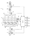
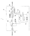
以下、図面を参照しながら、本発明の第1実施形態に係る制御装置について説明する。この第1実施形態は、制御装置を内燃機関の空燃比を制御するものとして構成した例であり、図1は、この制御装置1およびこれを適用した内燃機関3の概略構成を示している。同図に示すように、この制御装置1は、ECU2を備えており、このECU2は、後述するように、内燃機関(以下「エンジン」という)3の運転状態に応じて、これに供給する混合気の空燃比を制御する。
Hereinafter, a control device according to a first embodiment of the present invention will be described with reference to the drawings. The first embodiment is an example in which the control device is configured to control the air-fuel ratio of the internal combustion engine, and FIG. 1 shows a schematic configuration of the
このエンジン3は、図示しない車両に搭載された直列4気筒型ガソリンエンジンであり、第1〜第4の4つの気筒#1〜#4を備えている。このエンジン3の吸気管4のスロットル弁5の近傍には、例えばポテンショメータなどで構成されたスロットル弁開度センサ10が設けられている。このスロットル弁開度センサ10は、スロットル弁5の開度(以下「スロットル弁開度」という)θTHを検出して、その検出信号をECU2に送る。
The
さらに、吸気管4のスロットル弁5よりも下流側には、吸気管内絶対圧センサ11が設けられている。この吸気管内絶対圧センサ11(ゲインパラメータ検出手段、運転状態検出手段、動特性パラメータ検出手段)は、例えば半導体圧力センサなどで構成され、吸気管4内の吸気管内絶対圧PBAを検出し、その検出信号をECU2に出力する。
Further, an intake pipe
また、吸気管4は、インテークマニホールド4aの4つの分岐部4bを介して4つの気筒#1〜#4にそれぞれ接続されている。各分岐部4bには、各気筒の図示しない吸気ポートの上流側に、インジェクタ6が取り付けられている。各インジェクタ6は、エンジン3の運転時に、ECU2からの駆動信号によって、その開弁時間である最終燃料噴射量TOUTおよび噴射タイミングが制御される。
The
一方、エンジン3の本体には、例えばサーミスタなどで構成された水温センサ12が取り付けられている。水温センサ12は、エンジン3のシリンダブロック内を循環する冷却水の温度であるエンジン水温TWを検出し、その検出信号をECU2に出力する。
On the other hand, a
また、エンジン3のクランクシャフト(図示せず)には、クランク角センサ13が設けられている。このクランク角センサ13(ゲインパラメータ検出手段、運転状態検出手段、動特性パラメータ検出手段)は、クランクシャフトの回転に伴い、いずれもパルス信号であるCRK信号およびTDC信号をECU2に出力する。
A
CRK信号は、所定のクランク角(例えば30゜)ごとに1パルスが出力される。ECU2は、このCRK信号に応じ、エンジン3の回転数(以下「エンジン回転数」という)NEを算出する。また、TDC信号は、各気筒のピストン(図示せず)が吸気行程のTDC位置よりも若干、手前の所定のクランク角位置にあることを表す信号であり、所定クランク角ごとに1パルスが出力される。
One pulse of the CRK signal is output every predetermined crank angle (for example, 30 °). The
一方、排気管7(排気通路)のエキゾーストマニホールド7aよりも下流側には、上流側から順に第1および第2の触媒装置8a,8b(触媒)が間隔を存して設けられている。各触媒装置8は、NOx触媒と3元触媒を組み合わせたものであり、このNOx触媒は、図示しないが、イリジウム触媒(イリジウムを担持した炭化ケイ素ウイスカ粉末とシリカの焼成体)をハニカム構造の基材の表面に被覆し、その上にペロブスカイト型複酸化物(LaCoO3粉末とシリカの焼成体)をさらに被覆したものである。触媒装置8は、NOx触媒による酸化還元作用により、リーンバーン運転時の排気ガス中のNOxを浄化するとともに、3元触媒の酸化還元作用により、リーンバーン運転以外の運転時の排気ガス中のCO、HCおよびNOxを浄化する。なお、触媒装置8は、NOx触媒と3元触媒を組み合わせたものに限らず、排気ガス中のCO、HCおよびNOxを浄化できるものであればよい。例えば、触媒装置8を、ペロブスカイト型触媒などの非金属触媒および/または3元触媒などの金属触媒で構成してもよい。
On the other hand, on the downstream side of the
これらの第1および第2触媒装置8a,8bの間には、酸素濃度センサ(以下「O2センサ」という)15が取り付けられている。このO2センサ15(下流側空燃比センサ)は、ジルコニアおよび白金電極などで構成され、第1触媒装置8aの下流側の排気ガス中の酸素濃度に基づく出力VoutをECU2に送る。このO2センサ15の出力Vout(制御対象の出力)は、理論空燃比よりもリッチな混合気が燃焼したときには、ハイレベルの電圧値(例えば0.8V)となり、混合気がリーンのときには、ローレベルの電圧値(例えば0.2V)となるとともに、混合気が理論空燃比付近のときには、ハイレベルとローレベルの間の所定の目標値Vop(例えば0.6V)となる(図2参照)。
An oxygen concentration sensor (hereinafter referred to as “O2 sensor”) 15 is attached between the first and second
また、第1触媒装置8aよりも上流側のエキゾーストマニホールド7aの集合部付近には、LAFセンサ14(上流側空燃比センサ)が取り付けられている。このLAFセンサ14は、O2センサ15と同様のセンサとリニアライザなどの検出回路とを組み合わせることによって構成されており、リッチ領域からリーン領域までの広範囲な空燃比の領域において排気ガス中の酸素濃度をリニアに検出し、その酸素濃度に比例する出力KACTをECU2に送る。この出力KACTは、空燃比の逆数に比例する当量比として表される。
In addition, a LAF sensor 14 (upstream air-fuel ratio sensor) is attached in the vicinity of the aggregate portion of the
次に、図2を参照しながら、第1触媒装置8aの排気ガスの浄化率とO2センサ15の出力Vout(電圧値)との関係について説明する。同図は、第1触媒装置8aが、長時間の使用により浄化能力が低下した劣化状態と、浄化能力の高い未劣化状態の場合において、LAFセンサ14の出力KACTすなわちエンジン3に供給される混合気の空燃比が理論空燃比の付近で変化したときの、2つの第1触媒装置8aのHCおよびNOxの浄化率と、O2センサ15の出力Voutをそれぞれ測定した結果の一例を示している。同図において、破線で示すデータはいずれも、第1触媒装置8aが未劣化状態の場合の測定結果であり、実線で示すデータはいずれも、第1触媒装置8aが劣化状態の場合の測定結果である。また、LAFセンサ14の出力KACTが大きいほど、混合気の空燃比がよりリッチ側であることを示している。
Next, the relationship between the exhaust gas purification rate of the
同図に示すように、第1触媒装置8aが劣化している場合には、未劣化状態の場合と比べて、排気ガスの浄化能力が低下していることにより、LAFセンサ14の出力KACTがよりリーン側の値KACT1のときに、O2センサ15の出力Voutが目標値Vopを横切っている。一方、第1触媒装置8aは、その劣化・未劣化状態にかかわらず、O2センサ15の出力Voutが目標値Vopにあるときに、HCおよびNOxを最も効率よく浄化する特性を有している。したがって、O2センサ15の出力Voutが目標値Vopになるように、混合気の空燃比を制御することにより、第1触媒装置8aによって排気ガスを最も効率よく浄化できることが判る。このため、後述する空燃比制御では、O2センサ15の出力Voutが目標値Vopに収束するように、目標空燃比KCMDが制御される。
As shown in the figure, when the first
さらに、ECU2には、アクセル開度センサ16、大気圧センサ17、吸気温センサ18および車速センサ19などが接続されている。このアクセル開度センサ16は、車両の図示しないアクセルペダルの踏み込み量(以下「アクセル開度」という)APを検出し、その検出信号をECU2に出力する。また、大気圧センサ17、吸気温センサ18および車速センサ19はそれぞれ、大気圧PA、吸気温TAおよび車速VPを検出し、その検出信号をECU2に出力する。
Further, an
次に、ECU2(予測値算出手段や、制御入力算出手段、ゲインパラメータ検出手段、ゲイン設定手段、空燃比算出手段、運転状態検出手段、中間値算出手段、目標空燃比算出手段、乗算手段、補正係数設定手段)について説明する。 Next, ECU 2 (predicted value calculation means, control input calculation means, gain parameter detection means, gain setting means, air-fuel ratio calculation means, operating state detection means, intermediate value calculation means, target air-fuel ratio calculation means, multiplication means, correction coefficient setting hand stage) will be described.
このECU2は、I/Oインターフェース、CPU、RAMおよびROMなどからなるマイクロコンピュータから構成されており、前述した各種のセンサ10〜19の出力に応じて、エンジン3の運転状態を判別するとともに、ROMに予め記憶された制御プログラムやRAMに記憶されたデータなどに従って、後述する適応空燃比制御処理またはマップ検索処理を実行することにより、目標空燃比KCMD(制御入力)を算出する。さらに、後述するように、この目標空燃比KCMDに基づいて、インジェクタ6の最終燃料噴射量TOUTを気筒ごとに算出し、この算出した最終燃料噴射量TOUTに基づいた駆動信号で、インジェクタ6を駆動することにより、混合気の空燃比を制御する。
The
図3に示すように、制御装置1は、目標空燃比KCMDを算出するADSMコントローラ20およびPRISMコントローラ21を備えており、両コントローラ20,21はいずれも、具体的には、ECU2により構成されている。
As shown in FIG. 3, the
以下、ADSMコントローラ20(制御入力算出手段)について説明する。このADSMコントローラ20は、以下に述べる適応予測型ΔΣ変調制御(Adaptive prediction Delta Sigma Modulation Control:以下「ADSM」という)処理の制御アルゴリズムにより、O2センサ15の出力Voutを目標値Vopに収束させるための目標空燃比KCMDを算出するものであり、状態予測器22、オンボード同定器23およびDSMコントローラ24により構成されている。なお、このADSM処理の具体的なプログラムについては、後述する。
Hereinafter, the ADSM controller 20 (control input calculation means) will be described. The
まず、状態予測器22(予測値算出手段)について説明する。この状態予測器22は、以下に述べる予測アルゴリズムにより、出力偏差VO2の予測値PREVO2を予測(算出)するものである。本実施形態では、制御対象への制御入力を混合気の目標空燃比KCMDとし、制御対象の出力をO2センサ15の出力Voutとし、インジェクタ6を含むエンジン3の吸気系から、第1触媒装置8aを含む排気系の第1触媒装置8aの下流側のO2センサ15までの系を、制御対象と見なすとともに、この制御対象を、下式(1)に示すように、離散時間系モデルであるARXモデル(auto-regressive model with exogeneous input:外部入力を持つ自己回帰モデル)としてモデル化する。
First, the state predictor 22 (predicted value calculation means) will be described. The
VO2(k)=a1・VO2(k-1)+a2・VO2(k-2)+b1・DKCMD(k-dt) ……(1)
ここで、VO2は、O2センサ15の出力Voutと前述した目標値Vopとの偏差(Vout−Vop)である出力偏差を表し、DKCMDは、目標空燃比KCMD(=φop)と基準値FLAFBASEとの偏差(KCMD−FLAFBASE)である空燃比偏差を表し、記号kは、各データのサンプリングサイクルの順番を表している。この基準値FLAFBASEは、所定の一定値に設定される。また、a1,a2,b1はモデルパラメータを表しており、オンボード同定器23により、後述するように逐次同定される。
VO2 (k) = a1 · VO2 (k-1) + a2 · VO2 (k-2) + b1 · DKCMD (k-dt) ...... (1)
Here, VO2 represents an output deviation which is a deviation (Vout−Vop) between the output Vout of the
さらに、上記式(1)のdtは、目標空燃比KCMDの混合気がインジェクタ6により吸気系に供給されてから、O2センサ15の出力Voutに反映されるまでの予測時間を表しており、下式(2)のように定義される。
dt=d+d'+dd ……(2)
ここで、dは、LAFセンサ14からO2センサ15までの排気系のむだ時間を、d'は、インジェクタ6からLAFセンサ14までの空燃比操作系のむだ時間を、ddは、排気系と空燃比操作系との間の位相遅れ時間をそれぞれ表している(なお、後述する適応空燃比制御処理の制御プログラムでは、ADSM処理とPRISM処理とに切り換えて目標空燃比KCMDを算出する処理を行うため、位相遅れ時間dd=0に設定されている)。
Furthermore, dt in the above equation (1) represents the estimated time from when the air-fuel mixture of the target air-fuel ratio KCMD is supplied to the intake system by the
dt = d + d ′ + dd (2)
Here, d is the dead time of the exhaust system from the
以上のように、制御対象モデルを、出力偏差VO2の時系列データおよび空燃比偏差DKCMDで構成した理由は以下による。すなわち、一般に、制御対象モデルでは、制御対象の入出力と所定値との偏差を、入出力を表す変数として定義した場合の方が、入出力の絶対値を変数として定義した場合よりも、モデルパラメータをより正確に同定または定義できることで、制御対象モデルの動特性を制御対象の実際の動特性に適合させることができるという事実が知られている。したがって、本実施形態の制御装置1のように、制御対象モデルを、出力偏差VO2の時系列データおよび空燃比偏差DKCMDで構成することにより、O2センサ15の出力Voutおよび目標空燃比KCMDの絶対値を変数とする場合と比べて、制御対象の実際の動特性に対する制御対象モデルの動特性の適合性を向上させることができ、それにより予測値PREVO2の算出精度を向上させることができる。
As described above, the reason why the control target model is composed of the time series data of the output deviation VO2 and the air-fuel ratio deviation DKCMD is as follows. In other words, in general, in the control target model, the deviation between the input / output of the control target and the predetermined value is defined as a variable representing the input / output rather than the absolute value of the input / output defined as a variable. It is known that the parameters can be more accurately identified or defined so that the dynamic characteristics of the controlled object model can be adapted to the actual dynamic characteristics of the controlled object. Therefore, as in the
また、予測値PREVO2は、目標空燃比KCMDの混合気が吸気系に供給されてから予測時間dtが経過した後の出力偏差VO2(k+dt)を予測した値であり、上記式(1)に基づき、予測値PREVO2の算出式を導出すると、下式(3)が得られる。
PREVO2(k)≒VO2(k+dt)
=a1・VO2(k+dt-1)+a2・VO2(k+dt-2)+b1・DKCMD(k) ……(3)
The predicted value PREVO2 is a value obtained by predicting the output deviation VO2 (k + dt) after the predicted time dt has elapsed since the mixture of the target air-fuel ratio KCMD is supplied to the intake system, and is based on the above formula (1). When the calculation formula of the predicted value PREVO2 is derived, the following formula (3) is obtained.
PREVO2 (k) ≒ VO2 (k + dt)
= A1 · VO2 (k + dt-1) + a2 · VO2 (k + dt-2) + b1 · DKCMD (k) (3)
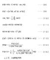
この式(3)では、出力偏差VO2(k)の未来値に相当するVO2(k+dt−1),VO2(k+dt−2)の算出が必要となり、実際にプログラム化するのは困難である。そのため、マトリクスA、Bを、モデルパラメータa1,a2,b1を用いて図4に示す式(4)、(5)のように定義するとともに、上式(3)の漸化式を繰り返し用いることにより、上式(3)を変形すると、図4に示す式(6)が得られる。予測アルゴリズムすなわち予測値PREVO2の算出式として、この式(6)を用いた場合、予測値PREVO2が、出力偏差VO2および空燃比偏差DKCMDにより算出される。 In this equation (3), it is necessary to calculate VO2 (k + dt−1) and VO2 (k + dt−2) corresponding to future values of the output deviation VO2 (k), and it is difficult to actually program them. Therefore, the matrices A and B are defined as the equations (4) and (5) shown in FIG. 4 using the model parameters a1, a2 and b1, and the recurrence equation of the above equation (3) is used repeatedly. By transforming the above equation (3), equation (6) shown in FIG. 4 is obtained. When this equation (6) is used as a calculation algorithm for the prediction algorithm, that is, the prediction value PREVO2, the prediction value PREVO2 is calculated from the output deviation VO2 and the air-fuel ratio deviation DKCMD.
次に、LAF出力偏差DKACTを、LAFセンサ14の出力KACT(=φin)と基準値FLAFBASEとの偏差(KACT−FLAFBASE)として定義すると、DKACT(k)=DKCMD(k−d')の関係が成立するので、この関係を図4の式(6)に適用すると、図4に示す式(7)が得られる。
Next, when the LAF output deviation DKACT is defined as a deviation (KACT−FLAFBASE) between the output KACT (= φin) of the
以上の式(6)または式(7)により算出される予測値PREVO2を用い、後述するように目標空燃比KCMDを算出することによって、制御対象の入出力間の応答遅れやむだ時間を適切に補償しながら、目標空燃比KCMDを算出することができる。特に、予測アルゴリズムとして、上記式(7)を用いた場合、予測値PREVO2が、出力偏差VO2、LAF出力偏差DKACTおよび空燃比偏差DKCMDにより算出されるので、第1触媒装置8aに実際に供給される排気ガスの空燃比の状態が反映された値として、予測値PREVO2を算出でき、その算出精度すなわち予測精度を上記式(6)を用いた場合よりも向上させることができる。また、式(7)を用いた場合において、d'≦1と見なせるときには、空燃比偏差DKCMDを用いることなく、出力偏差VO2およびLAF出力偏差DKACTのみにより、予測値PREVO2を算出できる。本実施形態では、LAFセンサ14がエンジン3に設けられているので、予測アルゴリズムとして上記式(7)を採用する。
By using the predicted value PREVO2 calculated by the above formula (6) or formula (7) and calculating the target air-fuel ratio KCMD as will be described later, the response delay and the dead time between the input and output of the controlled object are appropriately set. The target air-fuel ratio KCMD can be calculated while compensating. In particular, when the above equation (7) is used as the prediction algorithm, the predicted value PREVO2 is calculated from the output deviation VO2, the LAF output deviation DKACT, and the air-fuel ratio deviation DKCMD, and thus is actually supplied to the
なお、前述した式(1)の制御対象モデルは、DKACT(k)=DKCMD(k−d')の関係を適用することにより、出力偏差VO2およびLAF出力偏差DKACTを変数とするモデルとして定義することも可能である。 The above-described control target model of the equation (1) is defined as a model having the output deviation VO2 and the LAF output deviation DKACT as variables by applying the relationship of DKACT (k) = DKCMD (k−d ′). It is also possible.
次に、オンボード同定器23(同定手段、同定誤差算出手段、フィルタリング手段、むだ時間設定手段、規制範囲設定手段、重みパラメータ設定手段、パラメータ決定手段)について説明する。このオンボード同定器23は、以下に述べる逐次型同定アルゴリズムにより、前述した式(1)のモデルパラメータa1,a2,b1を同定(算出)するものである。具体的には、図5に示す式(8),(9)により、モデルパラメータのベクトルθ(k)を算出する。同図の式(8)において、KP(k)は、ゲイン係数のベクトルであり、ide_f(k)は同定誤差フィルタ値である。また、式(9)におけるθ(k)Tは、θ(k)の転置行列を表し、a1'(k)、a2'(k)およびb1'(k)は、後述するリミット処理を施す前のモデルパラメータを表している。なお、以下の説明では、「ベクトル」という表記を適宜、省略する。
Next, the on-board identifier 23 (identification means, identification error calculation means, filtering means, dead time setting means, restriction range setting means, weight parameter setting means, parameter determination means) will be described. The on-
上記式(8)の同定誤差フィルタ値ide_f(k)は、図5に示す式(11)〜(13)により算出される同定誤差ide(k)に、図5の式(10)に示す移動平均フィルタリング処理を施した値である。図5の式(10)のnは、移動平均フィルタリング処理のフィルタ次数(1以上の整数)を表しており、式(12)のVO2HAT(k)は、出力偏差VO2の同定値を表している。 The identification error filter value ide_f (k) of the above equation (8) is moved to the identification error ide (k) calculated by the equations (11) to (13) shown in FIG. This is a value subjected to average filtering processing. N in the equation (10) in FIG. 5 represents the filter order (an integer of 1 or more) of the moving average filtering process, and VO2HAT (k) in the equation (12) represents the identification value of the output deviation VO2. .
この同定誤差フィルタ値ide_f(k)を用いる理由は以下による。すなわち、本実施形態の制御対象は、目標空燃比KCMDを制御入力とし、O2センサ15の出力Voutを制御対象の出力とするものであり、その周波数特性としてはローパス特性を有している。このようなローパス特性を有する制御対象では、オンボード同定器23の同定アルゴリズム、具体的には後述する重み付き最小2乗法アルゴリズムの周波数重み特性に起因して、制御対象の高周波特性が強調された状態で、モデルパラメータが同定されるため、制御対象モデルのゲイン特性が制御対象の実際のゲイン特性よりも低くなる傾向を示す。その結果、制御装置1によりADSM処理またはPRISM処理が実行された際、オーバーゲイン状態になることで、制御系が発散状態になり、不安定になる可能性がある。
The reason for using this identification error filter value ide_f (k) is as follows. That is, the control target of the present embodiment uses the target air-fuel ratio KCMD as a control input and the output Vout of the
したがって、本実施形態では、重み付き最小2乗法アルゴリズムの周波数重み特性を適切に補正し、制御対象モデルのゲイン特性を、制御対象の実際のゲイン特性に一致させるために、上記同定誤差ide(k)に移動平均フィルタリング処理を施した同定誤差フィルタ値ide_f(k)を用いるとともに、後述するように、移動平均フィルタリング処理のフィルタ次数nを、排気ガスボリュームAB_SVに応じて設定している。 Therefore, in this embodiment, in order to appropriately correct the frequency weighting characteristic of the weighted least squares algorithm and to match the gain characteristic of the controlled object model with the actual gain characteristic of the controlled object, the identification error ide (k ) Is used as the identification error filter value ide_f (k) subjected to the moving average filtering process, and the filter order n of the moving average filtering process is set according to the exhaust gas volume AB_SV, as will be described later.
さらに、前述した図5の式(8)のゲイン係数のベクトルKP(k)は、図5の式(14)により算出される。この式(14)のP(k)は、図5の式(15)で定義される3次の正方行列である。 Further, the vector KP (k) of the gain coefficient in the above-described equation (8) in FIG. 5 is calculated by the equation (14) in FIG. P (k) in this equation (14) is a cubic square matrix defined by equation (15) in FIG.
以上のような同定アルゴリズムでは、式(15)の重みパラメータλ1、λ2の設定により、以下の4つの同定アルゴリズムのうちの1つが選択される。
すなわち、
λ1=1,λ2=0 ;固定ゲインアルゴリズム
λ1=1,λ2=1 ;最小2乗法アルゴリズム
λ1=1,λ2=λ ;漸減ゲインアルゴリズム
λ1=λ,λ2=1 ;重み付き最小2乗法アルゴリズム
ただし、λは、0<λ<1に設定される所定値。
In the identification algorithm as described above, one of the following four identification algorithms is selected according to the setting of the weight parameters λ1 and λ2 of Expression (15).
That is,
λ1 = 1, λ2 = 0; fixed gain algorithm λ1 = 1, λ2 = 1; least squares algorithm
λ1 = 1, λ2 = λ; gradually decreasing gain algorithm λ1 = λ, λ2 = 1; weighted least squares algorithm where λ is a predetermined value set to 0 <λ <1.
本実施形態では、これらの4つの同定アルゴリズムのうちの重み付き最小2乗法アルゴリズムを採用する。これは、重みパラメータλ1の値をエンジン3の運転状態、具体的には排気ガスボリュームAB_SVに応じて設定することにより、同定精度と、モデルパラメータの最適値への収束速度とを適切に設定できることによる。例えば、低負荷運転状態のときには、それに応じて重みパラメータλ1の値を値1に近い値に設定することで、すなわち最小2乗法アルゴリズムに近いアルゴリズムに設定することで、良好な同定精度を確保できるとともに、高負荷運転状態のときには、それに応じて重みパラメータλ1の値を低負荷運転状態のときよりも小さい値に設定することにより、モデルパラメータを迅速に最適値に収束させることができる。以上のように、重みパラメータλ1の値を排気ガスボリュームAB_SVに応じて設定することにより、同定精度と、モデルパラメータの最適値への収束速度とを適切に設定することができ、それにより、触媒後排気ガス特性を向上させることができる。
In the present embodiment, a weighted least square algorithm of these four identification algorithms is employed. This is because, by setting the value of the weight parameter λ1 according to the operating state of the
以上の式(8)〜(15)の同定アルゴリズムにおいて、前述したDKACT(k)=DKCMD(k−d')の関係を適用すると、図6に示す式(16)〜(23)の同定アルゴリズムが得られる。本実施形態では、LAFセンサ14がエンジン3に設けられているので、これらの式(16)〜(23)を用いる。これらの式(16)〜(23)を用いた場合、前述した理由により、モデルパラメータを、第1触媒装置8aに実際に供給される排気ガスの空燃比の状態がより反映された値として同定することができ、それにより、上記式(8)〜(15)の同定アルゴリズムを用いた場合よりも、モデルパラメータの同定精度を向上させることができる。
In the identification algorithms of the above equations (8) to (15), when the above-described relationship of DKACT (k) = DKCMD (k−d ′) is applied, the identification algorithms of equations (16) to (23) shown in FIG. Is obtained. In the present embodiment, since the
また、このオンボード同定器23では、以上の同定アルゴリズムにより算出されたモデルパラメータa1'(k)、a2'(k)およびb1'(k)に、後述するリミット処理を施すことにより、モデルパラメータa1(k)、a2(k)およびb1(k)が算出される。さらに、前述した状態予測器22では、このようにリミット処理を施した後のモデルパラメータa1(k)、a2(k)およびb1(k)に基づき、予測値PREVO2が算出される。
In addition, the on-
次に、DSMコントローラ24について説明する。このDSMコントローラ24は、ΔΣ変調アルゴリズムを応用した制御アルゴリズムにより、状態予測器22で算出された予測値PREVO2に基づき、制御入力φop(k)(=目標空燃比KCMD)を生成(算出)するとともに、これを制御対象に入力することにより、制御対象の出力としてのO2センサ15の出力Voutを目標値Vopに収束させるように制御するものである。
Next, the
まず、一般的なΔΣ変調アルゴリズムについて説明する。図7は、ΔΣ変調アルゴリズムを適用したコントローラ26により、制御対象27を制御する制御系の構成を示している。同図に示すように、このコントローラ26では、差分器26aにより、参照信号r(k)と遅延素子26bで遅延されたDSM信号u(k−1)との偏差として偏差信号δ(k)が生成される。次に、積分器26cにより、偏差積分値σd(k)が、偏差信号δ(k)と遅延素子26dで遅延された偏差積分値σd(k−1)との和の信号として生成される。次いで、量子化器26e(符号関数)により、DSM信号u(k)が、この偏差積分値σd(k)を符号化した信号として生成される。そして、以上のように生成されたDSM信号u(k)が制御対象27に入力されることにより、出力信号 y(k)が制御対象27から出力される。
First, a general ΔΣ modulation algorithm will be described. FIG. 7 shows a configuration of a control system in which the
以上のΔΣ変調アルゴリズムは、以下の数式(24)〜(26)で表される。
δ(k)=r(k)−u(k−1) ……(24)
σd(k)=σd(k−1)+δ(k) ……(25)
u(k)=sgn(σd(k)) ……(26)
ただし、符号関数sgn(σd(k))の値は、σd(k)≧0のときにはsgn(σd(k))=1となり、σd(k)<0のときにはsgn(σd(k))=−1となる(なお、σd(k)=0のときに、sgn(σd(k))=0と設定してもよい)。
The above ΔΣ modulation algorithm is expressed by the following mathematical formulas (24) to (26).
δ (k) = r (k) −u (k−1) (24)
σ d (k) = σ d (k−1) + δ (k) (25)
u (k) = sgn (σ d (k)) (26)
However, the value of the sign function sgn (σ d (k)) is, σ d (k) ≧ 0 sgn (σ d (k)) = 1 becomes when the, σ d (k) <0 sgn (σ d when the (k)) = − 1 (Note that when σ d (k) = 0, sgn (σ d (k)) = 0 may be set).
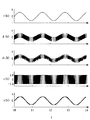
図8は、以上の制御系の制御シミュレーション結果を示している。同図に示すように、正弦波状の参照信号r(k)を制御系に入力した場合、DSM信号u(k)が矩形波状の信号として生成され、これを制御対象27に入力することにより、参照信号r(k)と異なる振幅で同じ周波数の、ノイズを有するものの全体として同様の波形の出力信号y(k)が、制御対象27から出力される。このように、ΔΣ変調アルゴリズムの特性は、参照信号r(k)から生成されたDSM信号u(k)を制御対象27に入力したときに、制御対象27の出力y(k)が、参照信号r(k)に対して、異なる振幅で同じ周波数の、全体として同様の波形の信号となるような値として、DSM信号u(k)を生成できるという点にある。言い換えれば、DSM信号u(k)を、参照信号r(k)が制御対象27の実際の出力y(k)に再現されるような値として、生成(算出)できるという点にある。
FIG. 8 shows a control simulation result of the above control system. As shown in the figure, when a sinusoidal reference signal r (k) is input to the control system, a DSM signal u (k) is generated as a rectangular wave signal, and this is input to the
DSMコントローラ24は、このようなΔΣ変調アルゴリズムの特性を利用し、O2センサ15の出力Voutを目標値Vopに収束させるための制御入力φop(k)を算出するものである。その原理について説明すると、例えば図9に1点鎖線で示すように、出力偏差VO2が値0に対して揺らいでいる場合(すなわち、O2センサ15の出力Voutが目標値Vopに対して揺らいでいる場合)、出力偏差VO2を値0に収束させる(すなわち出力Voutを目標値Vopに収束させる)には、図9に破線で示す、出力偏差VO2を打ち消すような逆位相波形の出力偏差VO2*が生じるように、制御入力φop(k)を生成すればよい。
The
しかし、前述したように、本実施形態の制御対象では、制御入力φop(k)としての目標空燃比KCMDが制御対象に入力されてからO2センサ15の出力Voutに反映されるまでに、予測時間dt分の時間遅れが発生するため、現在の出力偏差VO2に基づいて、制御入力φop(k)を算出した場合の出力偏差VO2#は、図9に実線で示すように、出力偏差VO2*に対して遅れを生じ、それにより、制御タイミングのずれが生じてしまう。したがって、これを補償するために、本実施形態のADSMコントローラ20におけるDSMコントローラ24では、出力偏差VO2の予測値PREVO2を用いることにより、制御入力φop(k)が、制御タイミングのずれを生じることなく、現在の出力偏差VO2を打ち消すような出力偏差(逆位相波形の出力偏差VO2*と同様の出力偏差)を生じさせる信号として生成される。
However, as described above, in the control target of the present embodiment, the estimated time from when the target air-fuel ratio KCMD as the control input φop (k) is input to the control target and reflected in the output Vout of the
具体的には、このDSMコントローラ24では、図10に示すように、反転増幅器24aにより、参照信号r(k)が、値−1、参照信号用のゲインGdおよび予測値PREVO2(k)を互いに乗算した信号として生成される。次に、差分器24bにより、この参照信号r(k)と遅延素子24cで遅延されたDSM信号u''(k−1)との偏差として偏差信号δ(k)が生成される。
More specifically, in the
次いで、積分器24dにより、偏差積分値σd(k)が、偏差信号δ(k)と遅延素子24eで遅延された偏差積分値σd(k−1)との和の信号として生成され、次に、量子化器24f(符号関数)により、DSM信号u''(k)が、この偏差積分値σd(k)を符号化した値として生成される。そして、増幅器24gにより、増幅DSM信号u(k)がDSM信号u''(k)を所定のゲインFdで増幅した値として生成され、次に、加算器24hにより、この増幅DSM信号u(k)を所定の基準値FLAFBASEに加算した値として、制御入力φop(k)が生成される。
Then, an
以上のDSMコントローラ24の制御アルゴリズムは、以下の式(27)〜(32)で表される。
r(k)=−1・Gd・PREVO2(k) ……(27)
δ(k)=r(k)−u''(k−1) ……(28)
σd(k)=σd(k−1)+δ(k) ……(29)
u''(k)=sgn(σd(k)) ……(30)
u(k)=Fd・u''(k) ……(31)
φop(k)=FLAFBASE+u(k) ……(32)
ここで、Gd,Fdはゲインを表す。また、符号関数sgn(σd(k))の値は、σd(k)≧0のときにはsgn(σd(k))=1となり、σd(k)<0のときにはsgn(σd(k))=−1となる(なお、σd(k)=0のときに、sgn(σd(k))=0と設定してもよい)。
The control algorithm of the
r (k) = − 1 · G d · PREVO2 (k) (27)
δ (k) = r (k) −u ″ (k−1) (28)
σ d (k) = σ d (k−1) + δ (k) (29)
u ″ (k) = sgn (σ d (k)) (30)
u (k) = F d · u ″ (k) (31)
φop (k) = FLAFBASE + u (k) (32)
Here, G d and F d represent gains. The value of the sign function sgn (σ d (k)) is, σ d (k) ≧ 0 sgn (σ d (k)) = 1 becomes when the, σ d (k) <0 sgn (σ d when the (k)) = − 1 (Note that when σ d (k) = 0, sgn (σ d (k)) = 0 may be set).
このDSMコントローラ24では、以上の式(27)〜(32)に示す制御アルゴリズムにより、前述したように、制御入力φop(k)が、制御タイミングのずれを生じることなく、出力偏差VO2を打ち消すような出力偏差VO2*を生じさせる値として算出される。すなわち、制御入力φop(k)が、O2センサ15の出力Voutを目標値Vopに収束させることができる値として算出される。また、制御入力φop(k)が、増幅DSM信号u(k)を所定の基準値FLAFBASEに加算した値として算出されるので、制御入力φop(k)を値0を中心して正負反転する値だけでなく、基準値FLAFBASEを中心として増減を繰り返す値として算出できる。これにより、通常のΔΣ変調アルゴリズムと比べて、制御の自由度を高めることができる。
In the
次に、前記PRISMコントローラ21について説明する。このPRISMコントローラ21は、以下に述べるオンボード同定型スライディングモード制御処理(以下「PRISM処理」という)の制御アルゴリズムにより、O2センサ15の出力Voutを目標値Vopに収束させるための目標空燃比KCMDを算出するものであり、状態予測器22、オンボード同定器23およびスライディングモードコントローラ(以下「SLDコントローラ」という)25により構成されている。なお、このPRISM処理の具体的なプログラムについては後述する。
Next, the
このPRISMコントローラ21のうちの状態予測器22およびオンボード同定器23については、既に説明したので、ここではSLDコントローラ25についてのみ説明する。このSLDコントローラ25は、スライディングモード制御アルゴリズムに基づいてスライディングモード制御を行うものであり、以下、一般的なスライディングモード制御アルゴリズムについて説明する。このスライディングモード制御アルゴリズムでは、前述した式(1)の離散時間系モデルを制御対象モデルとして用いるため、切換関数σは、下式(33)に示すように、出力偏差VO2の時系列データの線形関数として設定される。
σ(k)=S1・VO2(k)+S2・VO2(k−1) ……(33)
ここで、S1,S2は、−1<(S2/S1)<1の関係が成立するように設定される所定の係数である。
Since the
σ (k) = S1 · VO2 (k) + S2 · VO2 (k−1) (33)
Here, S1 and S2 are predetermined coefficients set so that the relationship of -1 <(S2 / S1) <1 is established.
一般にスライディングモード制御アルゴリズムでは、切換関数σが2つの状態変数(本実施形態では出力偏差VO2の時系列データ)で構成されている場合、2つの状態変数で構成される位相空間は、これらをそれぞれ縦軸および横軸とする2次元の位相平面となるため、この位相平面上において、σ=0を満たす2つの状態変数の値の組み合わせは、切換直線と呼ばれる直線上に載ることになる。したがって、制御対象への制御入力を、2つの状態変数の組み合わせが切換直線上に収束する(載る)ように適切に決定することにより、2つの状態変数をいずれも、値0になる平衡点に収束(スライディング)させることができる。さらに、スライディングモード制御アルゴリズムでは、切換関数σの設定により、状態変数の動特性、より具体的には収束挙動や収束速度を指定することができる。例えば、本実施形態のように、切換関数σが2つの状態変数で構成されている場合には、切換直線の傾きを値1に近づけると、状態変数の収束速度が遅くなる一方、値0に近づけると、収束速度が速くなる。
In general, in the sliding mode control algorithm, when the switching function σ is composed of two state variables (in this embodiment, time series data of the output deviation VO2), the phase space composed of the two state variables respectively Since the vertical axis and the horizontal axis are two-dimensional phase planes, the combination of the two state variable values satisfying σ = 0 is placed on a straight line called a switching straight line. Therefore, by appropriately determining the control input to the controlled object so that the combination of the two state variables converges on the switching straight line, both of the two state variables become equilibrium points where the value becomes zero. It can be converged (sliding). Furthermore, in the sliding mode control algorithm, it is possible to specify the dynamic characteristics of the state variable, more specifically the convergence behavior and the convergence speed, by setting the switching function σ. For example, as in the present embodiment, when the switching function σ is composed of two state variables, when the slope of the switching line is brought close to the
本実施形態では、前記式(33)に示すように、切換関数σが出力偏差VO2の2つの時系列データ、すなわち出力偏差VO2の今回値VO2(k)および前回値VO2(k−1)により構成されているので、これらの今回値VO2(k)および前回値VO2(k−1)の組み合わせを切換直線上に収束させるように、制御対象への制御入力すなわち目標空燃比KCMDを設定すればよい。具体的には、制御量Usl(k)を、基準値FLAFBASEとの和が目標空燃比KCMDとなる値として定義すると、今回値VO2(k)および前回値VO2(k−1)の組み合わせを切換直線上に収束させるための制御量Usl(k)は、適応スライディングモード制御アルゴリズムにより、図11に示す式(34)のように、等価制御入力Ueq(k)、到達則入力Urch(k)および適応則入力Uadp(k)の総和として設定される。 In the present embodiment, as shown in the equation (33), the switching function σ is based on two time-series data of the output deviation VO2, that is, the current value VO2 (k) and the previous value VO2 (k−1) of the output deviation VO2. If the control input to the controlled object, that is, the target air-fuel ratio KCMD is set so that the combination of the current value VO2 (k) and the previous value VO2 (k-1) converges on the switching line, Good. Specifically, when the control amount Usl (k) is defined as a value that is the sum of the reference value FLAFBASE and the target air-fuel ratio KCMD, the combination of the current value VO2 (k) and the previous value VO2 (k-1) is switched. The control amount Usl (k) for converging on the straight line is obtained from an equivalent control input Ueq (k), a reaching law input Urch (k), and an reaching control input Urch (k) by an adaptive sliding mode control algorithm as shown in Expression (34) shown in FIG. It is set as the sum of the adaptive law input Uadp (k).
この等価制御入力Ueq(k)は、出力偏差VO2の今回値VO2(k)および前回値VO2(k−1)の組み合わせを切換直線上に拘束しておくためのものであり、具体的には、図11に示す式(35)のように定義される。また、到達則入力Urch(k)は、外乱やモデル化誤差などにより、出力偏差VO2の今回値VO2(k)および前回値VO2(k−1)の組み合わせが切換直線上から外れた際に、これらを切換直線上に収束させるためのものであり、具体的には、図11に示す式(36)のように定義される。この式(36)において、Fはゲインを表す。 This equivalent control input Ueq (k) is for constraining the combination of the current value VO2 (k) and the previous value VO2 (k−1) of the output deviation VO2 on the switching straight line. , Is defined as shown in Expression (35) shown in FIG. Further, the reaching law input Urch (k) is generated when the combination of the current value VO2 (k) and the previous value VO2 (k−1) of the output deviation VO2 deviates from the switching straight line due to disturbance or modeling error. These are for convergence on the switching straight line, and are specifically defined as in Expression (36) shown in FIG. In this formula (36), F represents a gain.
さらに、適応則入力Uadp(k)は、制御対象の定常偏差、モデル化誤差および外乱の影響を抑制しながら、出力偏差VO2の今回値VO2(k)および前回値VO2(k−1)の組み合わせを、切換超平面上に確実に収束させるためのものであり、具体的には、図11に示す式(37)のように定義される。この式(37)において、Gはゲインを、ΔTは制御周期をそれぞれ表す。 Further, the adaptive law input Uadp (k) is a combination of the current value VO2 (k) and the previous value VO2 (k−1) of the output deviation VO2 while suppressing the influence of the steady-state deviation, modeling error and disturbance of the controlled object. Is reliably converged on the switching hyperplane, and is specifically defined as shown in Expression (37) shown in FIG. In this equation (37), G represents a gain, and ΔT represents a control period.
本実施形態のPRISMコントローラ21のSLDコントローラ25では、前述したように、出力偏差VO2に代えて予測値PREVO2を用いるので、PREVO2(k)≒VO2(k+dt)の関係を適用することにより、以上の式(33)〜(37)のアルゴリズムを、図12に示す式(38)〜(42)に書き換えて用いる。この式(38)におけるσPREは、予測値PREVO2を用いたときの切換関数(以下「予測切換関数」という)の値である。すなわち、このSLDコントローラ25では、以上のアルゴリズムで算出される制御量Usl(k)を基準値FLAFBASEに加算することによって、目標空燃比KCMDが算出される。
In the
以下、ECU2により実行される燃料噴射量の算出処理について、図13を参照しながら説明する。なお、以下の説明では、今回値であることを示す記号(k)を適宜、省略する。図13は、この制御処理のメインルーチンを示しており、本処理は、TDC信号の入力に同期して割り込み実行される。この処理では、後述する適応空燃比制御処理、またはマップ検索処理により算出された目標空燃比KCMDを用いることによって、燃料噴射量TOUTが気筒ごとに算出される。
Hereinafter, the fuel injection amount calculation process executed by the
まず、ステップ1(図では「S1」と略す。以下同じ)において、前述した各種のセンサ10〜19の出力を読み込むとともに、読み込んだデータをRAM内に記憶する。
First, in step 1 (abbreviated as “S1” in the figure, the same applies hereinafter), the outputs of the
次に、ステップ2に進み、基本燃料噴射量Timを算出する。この処理では、エンジン回転数NEおよび吸気管内絶対圧PBAに応じて、図示しないマップを検索することにより、基本燃料噴射量Timを算出する。 Next, the process proceeds to step 2, and the basic fuel injection amount Tim is calculated. In this process, the basic fuel injection amount Tim is calculated by searching a map (not shown) according to the engine speed NE and the intake pipe absolute pressure PBA.
次いで、ステップ3に進み、総補正係数KTOTALを算出する。この総補正係数KTOTALは、各種の運転パラメータ(例えば吸気温TAや、大気圧PA、エンジン水温TW、アクセル開度APなど)に応じて、各種のテーブルやマップを検索することで各種の補正係数を算出するとともに、これらの各種の補正係数を互いに乗算することにより、算出される。 Next, the process proceeds to step 3 where a total correction coefficient KTOTAL is calculated. This total correction coefficient KTOTAL is obtained by searching various tables and maps according to various operation parameters (for example, intake air temperature TA, atmospheric pressure PA, engine water temperature TW, accelerator pedal opening AP, etc.). Is calculated by multiplying these various correction coefficients with each other.
次に、ステップ4に進み、適応制御フラグF_PRISMONの設定処理を実行する。この処理の内容は図示しないが、具体的には、以下の(a)〜(f)の条件がいずれも成立しているときには、適応空燃比制御処理で算出された目標空燃比KCMDを使用する条件が成立しているとして、それを表すために、適応制御フラグF_PRISMONが「1」にセットされる。一方、(a)〜(f)の条件のうちの少なくとも1つが成立していないときには、適応制御フラグF_PRISMONが「0」にセットされる。
(a)LAFセンサ14およびO2センサ15がいずれも活性化していること。
(b)エンジン3がリーンバーン運転中でないこと。
(c)スロットル弁5が全開状態でないこと。
(d)点火時期の遅角制御中でないこと。
(e)フューエルカット運転中でないこと。
(f)エンジン回転数NEおよび吸気管内絶対圧PBAがいずれも、所定の範囲囲内の値であること。
Next, the process proceeds to step 4 where an adaptive control flag F_PRISMON setting process is executed. Although details of this process are not shown, specifically, when all of the following conditions (a) to (f) are satisfied, the target air-fuel ratio KCMD calculated in the adaptive air-fuel ratio control process is used. Assuming that the condition is satisfied, the adaptive control flag F_PRISMON is set to “1” to represent it. On the other hand, when at least one of the conditions (a) to (f) is not satisfied, the adaptive control flag F_PRISMON is set to “0”.
(A) Both the
(B) The
(C) The
(D) The ignition timing is not retarded.
(E) The fuel cut operation is not in progress.
(F) Both the engine speed NE and the intake pipe absolute pressure PBA are values within a predetermined range.
次に、ステップ5に進み、ステップ4で設定された適応制御フラグF_PRISMONが「1」であるか否かを判別する。この判別結果がYESのときには、ステップ6に進み、目標空燃比KCMDを、後述する適応空燃比制御処理で算出された適応目標空燃比KCMDSLDに設定する。
Next, the process proceeds to step 5 where it is determined whether or not the adaptive control flag F_PRISMON set in
一方、ステップ5の判別結果がNOのときには、ステップ7に進み、目標空燃比KCMDをマップ値KCMDMAPに設定する。このマップ値KCMDMAPは、エンジン回転数NEおよび吸気管内絶対圧PBAに応じて、図示しないマップを検索することにより、算出される。
On the other hand, when the determination result of
以上のステップ6または7に続くステップ8では、オブザーバフィードバック補正係数#nKLAFを気筒ごとに算出する。このオブザーバフィードバック補正係数#nKLAFは、気筒ごとの実際の空燃比のばらつきを補正するためのものであり、具体的には、オブザーバによりLAFセンサ14の出力KACTから気筒ごとの実際の空燃比を推定し、これらの推定した空燃比に応じて、PID制御により算出される。なお、このオブザーバフィードバック補正係数#nKLAFの記号#nは、気筒の番号#1〜#4を表すものであり、これは、後述する要求燃料噴射量#nTCYLおよび最終燃料噴射量#nTOUTにおいても同様である。
In
次いで、ステップ9に進み、フィードバック補正係数KFBを算出する。このフィードバック補正係数KFBは、具体的には、以下のように算出される。すなわち、LAFセンサ14の出力KACTと目標空燃比KCMDとの偏差に応じて、PID制御によりフィードバック係数KLAFを算出する。また、図示しないSelf Tuning Regulator 型の適応制御器によりフィードバック補正係数KSTRを算出し、これを目標空燃比KCMDで除算することにより、フィードバック補正係数kstrを算出する。そして、エンジン3の運転状態に応じて、これらの2つのフィードバック係数KLAFおよびフィードバック補正係数kstrの一方を、フィードバック補正係数KFBとして設定する。
Next, the process proceeds to step 9 to calculate a feedback correction coefficient KFB. Specifically, the feedback correction coefficient KFB is calculated as follows. That is, the feedback coefficient KLAF is calculated by PID control according to the deviation between the output KACT of the
次いで、ステップ10に進み、補正目標空燃比KCMDMを算出する。この補正目標空燃比KCMDMは、空燃比A/Fの変化による充填効率の変化を補償するためのものであり、前述したステップ6または7で算出された目標空燃比KCMDに応じて、図示しないテーブルを検索することにより算出される。
Next, the routine proceeds to step 10 where a corrected target air-fuel ratio KCMDM is calculated. The corrected target air-fuel ratio KCMDM is for compensating for the change in charging efficiency due to the change in the air-fuel ratio A / F, and is a table (not shown) according to the target air-fuel ratio KCMD calculated in
次に、ステップ11に進み、以上のように算出した基本燃料噴射量Tim、総補正係数KTOTAL、オブザーバフィードバック補正係数#nKLAF、フィードバック補正係数KFB、および補正目標空燃比KCMDMを用い、下式(43)により、気筒ごとの要求燃料噴射量#nTCYLを算出する。
#nTCYL=Tim・KTOTAL・KCMDM・KFB・#nKLAF
……(43)
Next, the process proceeds to step 11, and the basic fuel injection amount Tim, the total correction coefficient KTOTAL, the observer feedback correction coefficient #nKLAF, the feedback correction coefficient KFB, and the corrected target air-fuel ratio KCMDM calculated as described above are used. ) To calculate the required fuel injection amount #nTCYL for each cylinder.
# NTCYL = Tim, KTOTAL, KCMDM, KFB, #nKLAF
...... (43)
次に、ステップ12に進み、要求燃料噴射量#nTCYLを付着補正することにより、最終燃料噴射量#nTOUTを算出する。この最終燃料噴射量#nTOUTは、具体的には、今回の燃焼サイクルでインジェクタ6から噴射された燃料が燃焼室の内壁面に付着する割合などを、運転状態に応じて算出し、そのように算出した割合に基づいて、要求燃料噴射量#nTCYLを補正することにより、算出される。
Next, the process proceeds to step 12, and the final fuel injection amount #nTOUT is calculated by adhering the required fuel injection amount #nTCYL. Specifically, the final fuel injection amount #nTOUT is calculated according to the operation state, such as the ratio of the fuel injected from the
次いで、ステップ13に進み、以上のように算出した最終燃料噴射量#nTOUTに基づく駆動信号を、対応する気筒のインジェクタ6に出力した後、本処理を終了する。
Next, the routine proceeds to step 13 where a drive signal based on the final fuel injection amount #nTOUT calculated as described above is output to the
次に、図14および図15を参照しながら、ADSM処理およびPRISM処理を含む適応空燃比制御処理について説明する。この処理は、所定の周期(例えば10msec)で実行される。また、この処理では、エンジン3の運転状態に応じて、ADSM処理、PRISM処理、またはスライディングモード制御量DKCMDSLDを所定値SLDHOLDに設定する処理により、目標空燃比KCMDが算出される。
Next, the adaptive air-fuel ratio control process including the ADSM process and the PRISM process will be described with reference to FIGS. 14 and 15. This process is executed at a predetermined cycle (for example, 10 msec). In this process, the target air-fuel ratio KCMD is calculated by the ADSM process, PRISM process, or the process of setting the sliding mode control amount DKCMDSLD to the predetermined value SLDHOLD according to the operating state of the
この処理では、まず、ステップ20において、F/C後判定処理を実行する。この処理の内容は図示しないが、この処理では、フューエルカット運転中は、それを表すためにF/C後判定フラグF_AFCが「1」にセットされ、フューエルカット運転の終了後、所定時間X_TM_AFCが経過したときには、それを表すためにF/C後判定フラグF_AFCが「0」にセットされる。
In this process, first, in
次に、ステップ21に進み、車速VPに基づいて、エンジン3を搭載した車両が発進したか否かを判定する発進判定処理を実行する。図16に示すように、この処理では、まず、ステップ49において、アイドル運転フラグF_IDLEが「1」であるか否かを判別する。このアイドル運転フラグF_IDLEは、アイドル運転中であるときに「1」に、それ以外のときに「0」にセットされる。
Next, it progresses to step 21 and the start determination process which determines whether the vehicle carrying the
この判別結果がYESで、アイドル運転中であるときには、ステップ50に進み、車速VPが所定車速VSTART(例えば1km/h)より小さいか否かを判別する。この判別結果がYESで、停車中であるときには、ステップ51に進み、ダウンカウント式の第1発進判定タイマのタイマ値TMVOTVSTを第1所定時間TVOTVST(例えば3msec)に設定する。 When the determination result is YES and the idling operation is being performed, the process proceeds to step 50 to determine whether or not the vehicle speed VP is lower than a predetermined vehicle speed VSTART (for example, 1 km / h). If the determination result is YES and the vehicle is stopped, the routine proceeds to step 51, where the timer value TMVOTVST of the down-counting first start determination timer is set to a first predetermined time TVOTVST (for example, 3 msec).
次いで、ステップ52に進み、ダウンカウント式の第2発進判定タイマのタイマ値TMVSTを、上記第1所定時間TVOTVSTよりも長い第2所定時間TVST(例えば500msec)に設定する。次いで、ステップ53,54において、第1および第2発進フラグF_VOTVST,F_VSTをいずれも「0」にセットした後、本処理を終了する。
Next, the routine proceeds to step 52, where the timer value TMVST of the down-count type second start determination timer is set to a second predetermined time TVST (for example, 500 msec) longer than the first predetermined time TVOTVST. Next, in
一方、ステップ49または50の判別結果がNOのとき、すなわちアイドル運転中でないか、または車両が発進したときには、ステップ55に進み、第1発進判定タイマのタイマ値TMVOTVSTが値0より大きいか否かを判別する。この判別結果がYESで、アイドル運転の終了後または車両の発進後、第1所定時間TVOTVSTが経過していないときには、第1発進モード中であるとして、ステップ56に進み、それを表すために第1発進フラグF_VOTVSTを「1」にセットする。
On the other hand, when the determination result of
一方、ステップ55の判別結果がNOで、アイドル運転の終了後または車両の発進後、第1所定時間TVOTVSTが経過したときには、第1発進モードが終了したとして、ステップ57に進み、第1発進フラグF_VOTVSTを「0」にセットする。
On the other hand, if the determination result in
ステップ56または57に続くステップ58では、第2発進判定タイマのタイマ値TMVSTが値0より大きいか否かを判別する。この判別結果がYESで、アイドル運転の終了後または車両の発進後、第2所定時間TVSTが経過していないときには、第2発進モード中であるとして、ステップ59に進み、それを表すために第2発進フラグF_VSTを「1」にセットした後、本処理を終了する。
In
一方、ステップ58の判別結果がNOで、アイドル運転の終了後または車両の発進後、第2所定時間TVSTが経過したときには、第2発進モードが終了したとして、前記ステップ54を実行した後、本処理を終了する。
On the other hand, if the determination result in
図14に戻り、ステップ21に続くステップ22では、状態変数の設定処理を実行する。図示しないが、この処理では、RAM内に記憶されている、目標空燃比KCMD、LAFセンサ14の出力KACTおよび出力偏差VO2の時系列データをいずれも、1サンプリングサイクル分ずつ過去側にシフトさせる。その後、KCMD、KACTおよびVO2の時系列データの最新の値と、基準値FLAFBASEと、後述する適応補正項FLAFADPとに基づき、KCMD、KACTおよびVO2の今回値を算出する。
Returning to FIG. 14, in
次に、ステップ23に進み、PRISM/ADSM処理の実行判定処理を行う。この処理は、PRISM処理またはADSM処理の実行条件が成立しているか否かを判定するものであり、具体的には、図17に示すフローチャートのように実行される。 Next, the process proceeds to step 23 where execution determination processing for PRISM / ADSM processing is performed. This process determines whether or not the execution condition for the PRISM process or the ADSM process is satisfied, and is specifically executed as shown in the flowchart of FIG.
すなわち、図17のステップ60〜63において、以下の(g)〜(j)の条件がいずれも成立しているときには、PRISM処理またはADSM処理を実行すべき運転状態にあるとして、それを表すために、ステップ64で、PRISM/ADSM実行フラグF_PRISMCALを「1」にセットした後、本処理を終了する。一方、(g)〜(j)の条件の少なくとも1つが成立していないときには、PRISM処理またはADSM処理を実行すべき運転状態にないとして、それを表すために、ステップ65で、PRISM/ADSM実行フラグF_PRISMCALを「0」にセットした後、本処理を終了する。
(g)O2センサ15が活性化していること。
(h)LAFセンサ14が活性化していること。
(i)エンジン3がリーンバーン運転中でないこと。
(j)点火時期の遅角制御中でないこと。
That is, in
(G) The
(H) The
(I) The
(J) The ignition timing is not retarded.
図14に戻り、ステップ23に続くステップ24では、同定器演算の実行判定処理を行う。この処理は、オンボード同定器23によるパラメータ同定の実行条件が成立しているか否かを判定するものであり、具体的には、図18に示すフローチャートのように実行される。
Returning to FIG. 14, in
すなわち、図18のステップ70および71の判別結果がいずれもNOのとき、言い換えれば、スロットル弁開度θTHが全開状態でなく、かつフューエルカット運転中でないときには、パラメータ同定を実行すべき運転状態であるとして、ステップ72に進み、同定実行フラグF_IDCALを「1」にセットした後、本処理を終了する。一方、ステップ70または71の判別結果がYESのときには、パラメータ同定を実行すべき運転状態にないとして、ステップ73に進み、同定実行フラグF_IDCALを「0」にセットした後、本処理を終了する。
That is, when the determination results of
図14に戻り、ステップ24に続くステップ25では、各種パラメータ(排気ガスボリュームAB_SVなど)を算出する。この処理の具体的な内容は、後述する。
Returning to FIG. 14, in
次に、ステップ26に進み、前記ステップ23で設定されたPRISM/ADSM実行フラグF_PRISMCALが「1」であるか否かを判別する。この判別結果がYESで、PRISM処理またはADSM処理の実行条件が成立しているときには、ステップ27に進み、前記ステップ24で設定された同定実行フラグF_IDCALが「1」であるか否かを判別する。
Next, the process proceeds to step 26, where it is determined whether or not the PRISM / ADSM execution flag F_PRISMCAL set in
この判別結果がYESで、オンボード同定器23によるパラメータ同定を実行すべき運転状態のときには、ステップ28に進み、パラメータ初期化フラグF_IDRSETが「1」であるか否かを判別する。この判別結果がNOで、RAMに記憶されているモデルパラメータa1,a2,b1の初期化が不要であるときには、後述するステップ31に進む。
If the determination result is YES and the operation state is to execute parameter identification by the on-
一方、この判別結果がYESで、モデルパラメータa1,a2,b1の初期化が必要であるときには、ステップ29に進み、モデルパラメータa1,a2,b1を、それぞれの初期値に設定した後、それを表すためにステップ30に進み、パラメータ初期化フラグF_IDRSETを「0」にセットする。 On the other hand, if the determination result is YES and the model parameters a1, a2, b1 need to be initialized, the process proceeds to step 29, where the model parameters a1, a2, b1 are set to their initial values and then In order to represent it, the process proceeds to step 30, and the parameter initialization flag F_IDRSET is set to “0”.
このステップ30または28に続くステップ31では、オンボード同定器23の演算を実行し、モデルパラメータa1,a2,b1を同定した後、後述する図15のステップ32に進む。このオンボード同定器23の演算の具体的な内容については、後述する。
In step 31 following
一方、ステップ27の判別結果がNOで、パラメータ同定を実行すべき運転状態でないときには、以上のステップ28〜31をスキップして、図15のステップ32に進む。ステップ27または31に続くステップ32では、モデルパラメータa1,a2,b1として、同定値または所定値を選択する。この処理の内容は図示しないが、具体的には、前記ステップ24で設定された同定実行フラグF_IDCALが「1」のときには、モデルパラメータa1,a2,b1をステップ31で同定された同定値に設定する。一方、同定実行フラグF_IDCALが「0」のときには、モデルパラメータa1,a2,b1を所定値に設定する。
On the other hand, if the determination result in
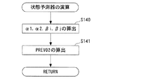
次に、ステップ33に進み、後述するように、状態予測器22の演算を実行し、予測値PREVO2を算出する。その後、ステップ34に進み、後述するように、制御量Uslを算出する。
Next, the process proceeds to step 33, where the
次いで、ステップ35に進み、SLDコントローラ25の安定判別を実行する。この処理の内容は図示しないが、具体的には、予測切換関数σPREの値に基づき、SLDコントローラ25によるスライディングモード制御が安定状態にあるか否かを判別する。
Next, the routine proceeds to step 35, where the stability determination of the
次に、ステップ36および37において、後述するように、SLDコントローラ25およびDSMコントローラ24により、スライディングモード制御量DKCMDSLDおよびΔΣ変調制御量DKCMDDSMをそれぞれ算出する。
Next, in
次いで、ステップ38に進み、後述するように、SLDコントローラ25により算出されたスライディングモード制御量DKCMDSLD、またはDSMコントローラ24により算出されたΔΣ変調制御量DKCMDDSMを用いて、適応目標空燃比KCMDSLDを算出する。この後、ステップ39に進み、後述するように、適応補正項FLAFADPを算出した後、本処理を終了する。
Next, the routine proceeds to step 38, where the adaptive target air-fuel ratio KCMDLSLD is calculated using the sliding mode control amount DKCMDDSLD calculated by the
一方、図14に戻り、前記ステップ26の判別結果がNOで、PRISM処理およびADSM処理の実行条件がいずれも成立していないときには、ステップ40に進み、パラメータ初期化フラグF_IDRSETを「1」にセットする。次に、図15のステップ41に進み、スライディングモード制御量DKCMDSLDを所定値SLDHOLDにセットする。次いで、前述したステップ38,39を実行した後、本処理を終了する。
On the other hand, returning to FIG. 14, if the determination result in
次に、図19を参照しながら、前述したステップ25の各種パラメータを算出する処理について説明する。この処理では、まず、ステップ80において、下式(44)により、排気ガスボリュームAB_SV(空間速度の推定値)を算出する。
AB_SV=(NE/1500)・PBA・X_SVPRA ……(44)
ここで、X_SVPRAは、エンジン排気量に基づいて決定される所定の係数である。
Next, the process for calculating various parameters in
AB_SV = (NE / 1500) · PBA · X_SVPRA (44)
Here, X_SVPRA is a predetermined coefficient determined based on the engine displacement.
次に、ステップ81に進み、前述した空燃比操作系のむだ時間KACT_D(=d')、排気系のむだ時間CAT_DELAY(=d)および予測時間dtを算出する。具体的には、ステップ80で算出された排気ガスボリュームAB_SVに応じて、図20に示すテーブルを検索することにより、むだ時間KACT_D,CAT_DELAYをそれぞれ算出するとともに、これらの和(KACT_D+CAT_DELAY)を予測時間dtとして設定する。すなわち、この制御プログラムでは、位相遅れ時間ddが値0に設定される。
Next, the routine proceeds to step 81, where the above-described dead time KACT_D (= d ′) of the air-fuel ratio operation system, the dead time CAT_DELAY (= d) of the exhaust system, and the predicted time dt are calculated. Specifically, the dead time KACT_D and CAT_DELAY are calculated by searching the table shown in FIG. 20 according to the exhaust gas volume AB_SV calculated in
このテーブルでは、排気ガスボリュームAB_SVが大きいほど、むだ時間KACT_D,CAT_DELAYがより小さい値に設定されている。これは、排気ガスボリュームAB_SVが大きいほど、排気ガスの流速が大きくなることで、むだ時間KACT_D,CAT_DELAYが短くなることによる。以上のように、むだ時間KACT_D,CAT_DELAYおよび予測時間dtが、排気ガスボリュームに応じて算出されるので、これらを用いて算出した出力偏差VO2の予測値PREVO2に基づき、後述する適応目標空燃比KCMDSLDを算出することにより、制御対象の入出力間の制御タイミングのずれを解消することができる。また、モデルパラメータa1,a2,b1が、上記むだ時間CAT_DELAYを用いて同定されるので、制御対象モデルの動特性を、制御対象の実際の動特性に適合させることができ、それにより、制御対象の入出力間の制御タイミングのずれをさらに解消することができる。 In this table, the dead times KACT_D and CAT_DELAY are set to smaller values as the exhaust gas volume AB_SV is larger. This is because the dead time KACT_D, CAT_DELAY is shortened by increasing the exhaust gas flow velocity as the exhaust gas volume AB_SV is increased. As described above, the dead times KACT_D and CAT_DELAY and the predicted time dt are calculated according to the exhaust gas volume, and therefore, based on the predicted value PREVO2 of the output deviation VO2 calculated using these, the adaptive target air-fuel ratio KCMDLSLD described later. By calculating, it is possible to eliminate the control timing shift between the input and output of the control target. In addition, since the model parameters a1, a2, and b1 are identified using the dead time CAT_DELAY, the dynamic characteristics of the controlled object model can be adapted to the actual dynamic characteristics of the controlled object, and thereby the controlled object. The control timing shift between the input and output can be further eliminated.
次に、ステップ82に進み、同定アルゴリズムの重みパラメータλ1,λ2の値を算出する。具体的には、重みパラメータλ2を値1に設定すると同時に、重みパラメータλ1を、排気ガスボリュームAB_SVに応じて、図21に示すテーブルを検索することにより算出する。
Next, proceeding to step 82, the values of the weighting parameters λ1 and λ2 of the identification algorithm are calculated. Specifically, the weight parameter λ2 is set to the
このテーブルでは、排気ガスボリュームAB_SVが大きいほど、重みパラメータλ1がより小さい値に設定されており、言い換えれば、排気ガスボリュームAB_SVが小さいほど、重みパラメータλ1がより大きくかつ値1により近い値に設定されている。これは、排気ガスボリュームAB_SVが大きいほど、言い換えれば高負荷運転状態であるほど、モデルパラメータの同定をより迅速に行う必要があるので、重みパラメータλ1をより小さく設定することによって、モデルパラメータの最適値への収束速度を高めるためである。これに加えて、排気ガスボリュームAB_SVが小さいほど、すなわち低負荷運転状態であるほど、空燃比が変動しやすくなり、触媒後排気ガス特性が不安定になりやすいことで、モデルパラメータの良好な同定精度を確保する必要があるので、重みパラメータλ1を値1に近づける(最小2乗法アルゴリズムに近づける)ことによって、モデルパラメータの同定精度をより高めるためである。
In this table, the larger the exhaust gas volume AB_SV, the smaller the weight parameter λ1 is set. In other words, the smaller the exhaust gas volume AB_SV is, the larger the weight parameter λ1 is set to a value closer to the
次に、ステップ83に進み、モデルパラメータa1,a2の値を制限するための下限値X_IDA2Lと、モデルパラメータb1の値を制限するための下限値X_IDB1Lおよび上限値X_IDB1Hとを、排気ガスボリュームAB_SVに応じて、図22に示すテーブルを検索することにより算出する。 Next, the routine proceeds to step 83 where the lower limit value X_IDA2L for limiting the values of the model parameters a1 and a2, and the lower limit value X_IDB1L and the upper limit value X_IDB1H for limiting the value of the model parameter b1 are set to the exhaust gas volume AB_SV. Accordingly, the calculation is performed by searching the table shown in FIG.
このテーブルでは、下限値X_IDA2Lは、排気ガスボリュームAB_SVが大きいほど、より大きい値に設定されている。これは、排気ガスボリュームAB_SVの変化に応じたむだ時間の増減に伴い、制御系が安定状態となるモデルパラメータa1,a2の組み合わせが変化することによる。また、下限値X_IDB1Lおよび上限値X_IDB1Hも、排気ガスボリュームAB_SVが大きいほど、より大きい値に設定されている。これは、排気ガスボリュームAB_SVが大きいほど、触媒前空燃比(第1触媒装置8aよりも上流側の排気ガスの空燃比)がO2センサ15の出力Voutに及ぼす影響の度合、すなわち制御対象のゲインがより大きくなることによる。
In this table, the lower limit value X_IDA2L is set to a larger value as the exhaust gas volume AB_SV is larger. This is because the combination of the model parameters a1 and a2 at which the control system becomes stable changes as the dead time increases or decreases according to the change in the exhaust gas volume AB_SV. Further, the lower limit value X_IDB1L and the upper limit value X_IDB1H are also set to larger values as the exhaust gas volume AB_SV is larger. This is because the larger the exhaust gas volume AB_SV is, the degree of the influence of the pre-catalyst air-fuel ratio (the air-fuel ratio of the exhaust gas upstream of the
次いで、ステップ84に進み、移動平均フィルタリング処理のフィルタ次数nを算出した後、本処理を終了する。この処理では、フィルタ次数nを、排気ガスボリュームAB_SVに応じて、図23に示すテーブルを検索することにより、算出する。 Next, the process proceeds to step 84, and after calculating the filter order n of the moving average filtering process, this process ends. In this process, the filter order n is calculated by searching the table shown in FIG. 23 according to the exhaust gas volume AB_SV.
このテーブルでは、排気ガスボリュームAB_SVが大きいほど、フィルタ次数nがより小さい値に設定されている。これは、以下の理由による。すなわち、前述したように、排気ガスボリュームAB_SVが変化すると、制御対象の周波数特性、特にゲイン特性が変化するので、制御対象モデルのゲイン特性を、制御対象の実際のゲイン特性に一致させるためには、重み付き最小2乗法アルゴリズムの周波数重み特性を、排気ガスボリュームAB_SVに応じて適切に補正する必要がある。したがって、移動平均フィルタリング処理のフィルタ次数nを、上記テーブルのように排気ガスボリュームAB_SVに応じて設定することにより、排気ガスボリュームAB_SVの変化にかかわらず、一定の同定重みを同定アルゴリズムにおいて確保できるとともに、制御対象モデルと制御対象との間で互いのゲイン特性を一致させることができ、これにより、同定精度を向上させることができる。 In this table, the filter order n is set to a smaller value as the exhaust gas volume AB_SV is larger. This is due to the following reason. That is, as described above, when the exhaust gas volume AB_SV changes, the frequency characteristic, particularly the gain characteristic, of the controlled object changes, so that the gain characteristic of the controlled object model matches the actual gain characteristic of the controlled object. It is necessary to appropriately correct the frequency weighting characteristic of the weighted least squares algorithm according to the exhaust gas volume AB_SV. Therefore, by setting the filter order n of the moving average filtering process according to the exhaust gas volume AB_SV as in the above table, a constant identification weight can be secured in the identification algorithm regardless of the change in the exhaust gas volume AB_SV. The gain characteristics of the controlled object model and the controlled object can be made to coincide with each other, thereby improving the identification accuracy.
次に、図24を参照しながら、前記ステップ31のオンボード同定器23の演算処理について説明する。同図に示すよ
うに、この処理では、まず、ステップ90において、前述した式(22)より、ゲイン係数KP(k)を算出する。次に、ステップ91に進み、前述した式(20)より、出力偏差VO2の同定値VO2HAT(k)を算出する。
Next, the calculation process of the on-
次いで、ステップ92に進み、前述した式(18)(19)より、同定誤差フィルタ値ide_f(k)を算出する。次に、ステップ93に進み、前述した式(16)より、モデルパラメータのベクトルθ(k)を算出した後、ステップ94に進み、モデルパラメータのベクトルθ(k)の安定化処理を実行する。この処理については後述する。 Next, the routine proceeds to step 92, where the identification error filter value ide_f (k) is calculated from the aforementioned equations (18) and (19). Next, the process proceeds to step 93, and after calculating the model parameter vector θ (k) from the above-described equation (16), the process proceeds to step 94, and the stabilization process of the model parameter vector θ (k) is executed. This process will be described later.
次いで、ステップ95に進み、前述した式(23)より、正方行列P(k)の次回値P(k+1)を算出する。この次回値P(k+1)は、次回のループでの算出において、正方行列P(k)の値として用いられる。 Next, the routine proceeds to step 95, where the next value P (k + 1) of the square matrix P (k) is calculated from the aforementioned equation (23). This next value P (k + 1) is used as the value of the square matrix P (k) in the next calculation in the loop.
以下、図25を参照しながら、上記ステップ94におけるモデルパラメータのベクトルθ(k)の安定化処理について説明する。同図に示すように、まず、ステップ100で、3つのフラグF_A1STAB,F_A2STAB,F_B1STABをいずれも「0」にセットする。
The process for stabilizing the model parameter vector θ (k) in
次に、ステップ101に進み、後述するように、a1'&a2'のリミット処理を実行する。次いで、ステップ102で、後述するように、b1'のリミット処理を実行した後、本処理を終了する。
Next, the process proceeds to step 101, and a limit process of a1 ′ & a2 ′ is executed as will be described later. Next, at
以下、図26を参照しながら、上記ステップ101のa1'&a2'のリミット処理について説明する。同図に示すように、まず、ステップ110において、前記ステップ93で算出したモデルパラメータの同定値a2'が、前記図19のステップ83で算出された下限値X_IDA2L以上であるか否かを判別する。この判別結果がNOのときには、ステップ111に進み、制御系を安定化させるために、モデルパラメータa2を下限値X_IDA2Lに設定すると同時に、モデルパラメータa2の安定化を実行したことを表すために、フラグF_A2STABを「1」にセットする。一方、この判別結果がYESで、a2'≧X_IDA2Lのときには、ステップ112に進み、モデルパラメータa2を同定値a2'に設定する。
Hereinafter, the a1 ′ & a2 ′ limit process in
これらのステップ111または112に続くステップ113では、前記ステップ93で算出したモデルパラメータの同定値a1'が、所定の下限値X_IDA1L(例えば値−2以上で値0より小さい一定値)以上であるか否かを判別する。この判別結果がNOのときには、ステップ114に進み、制御系を安定化させるために、モデルパラメータa1を下限値X_IDA1Lに設定すると同時に、モデルパラメータa1の安定化を実行したことを表すために、フラグF_A1STABを「1」にセットする。
In
一方、ステップ113の判別結果がYESのときには、ステップ115に進み、同定値a1'が、所定の上限値X_IDA1H(例えば値2)以下であるか否かを判別する。この判別結果がYESで、X_IDA1L≦a1'≦X_IDA1Hのときには、ステップ116に進み、モデルパラメータa1を同定値a1'に設定する。一方、この判別結果がNOで、X_IDA1H<a1'のときには、ステップ117に進み、モデルパラメータa1を上限値X_IDA1Hに設定すると同時に、モデルパラメータa1の安定化を実行したことを表すために、フラグF_A1STABを「1」にセットする。
On the other hand, when the determination result of
これらのステップ114、116または117に続くステップ118では、以上のように算出したモデルパラメータa1の絶対値と、モデルパラメータa2との和(|a1|+a2)が、所定の判定値X_A2STAB(例えば値0.9)以下であるか否かを判別する。この判別結果がYESのときには、モデルパラメータa1,a2の組み合わせが、制御系の安定性を確保できる範囲(図27にハッチングで示す規制範囲)内にあるとして、そのまま本処理を終了する。
In
一方、ステップ118の判別結果がNOのときには、ステップ119に進み、モデルパラメータa1が、判定値X_A2STABから下限値X_IDA2Lを減算した値(X_A2STAB−X_IDA2L)以下であるか否かを判別する。この判別結果がYESのときには、ステップ120に進み、モデルパラメータa2を、判定値X_A2STABからモデルパラメータa1の絶対値を減算した値(X_A2STAB−|a1|)に設定すると同時に、モデルパラメータa2の安定化を実行したことを表すために、フラグF_A2STABを「1」にセットした後、本処理を終了する。
On the other hand, when the determination result in
一方、ステップ119の判別結果がNOで、a1>(X_A2STAB−X_IDA2L)のときには、ステップ121に進み、制御系を安定化させるために、モデルパラメータa1を、判定値X_A2STABから下限値X_IDA2Lを減算した値(X_A2STAB−X_IDA2L)に設定し、モデルパラメータa2を下限値X_IDA2Lに設定する。これと同時に、モデルパラメータa1,a2の安定化を実行したことを表すために、フラグF_A1STAB,F_A2STABをいずれも「1」にセットする。その後、本処理を終了する。
On the other hand, if the determination result in
前述したように、逐次型の同定アルゴリズムでは、制御対象の入出力が定常状態になると、自己励起条件の不足化に起因して、同定されたモデルパラメータの絶対値が増大する、いわゆるドリフト現象が発生しやすくなることで、制御系が不安定になったり、振動状態になったりすることがある。また、その安定限界も、エンジン3の運転状態に応じて変化する。例えば、低負荷運転状態のときには、排気ガスボリュームAB_SVが小さくなることで、供給された混合気に対する排気ガスの応答遅れやむだ時間などが大きくなり、それにより、O2センサ15の出力Voutが振動状態になりやすい。
As described above, in the sequential identification algorithm, when the input / output of the controlled object is in a steady state, the so-called drift phenomenon in which the absolute value of the identified model parameter increases due to insufficient self-excitation conditions occurs. When it occurs easily, the control system may become unstable or vibrate. The stability limit also changes according to the operating state of the
これに対して、以上のa1'&a2'のリミット処理では、モデルパラメータa1,a2の組み合わせが、図27にハッチングで示す規制範囲内の値に収まるように設定されるとともに、この規制範囲を決定する下限値X_IDA2Lが、排気ガスボリュームAB_SVに応じて設定されるので、この規制範囲をエンジン3の運転状態の変化、すなわち制御対象の動特性の変化に伴う安定限界の変化が反映された適切な安定限界の範囲として設定することができ、そのような規制範囲内に収まるように規制されたモデルパラメータa1,a2を用いることにより、上記ドリフト現象の発生を回避でき、制御系の安定性を確保することができる。これに加えて、モデルパラメータa1,a2の組み合わせを、制御系の安定性を確保できる上記規制範囲内の値として設定することにより、モデルパラメータa1およびモデルパラメータa2を単独で規制した場合における、制御系の不安定な状態の発生を回避できる。以上により、制御系の安定性を向上させることができ、触媒後排気ガス特性を向上させることができる。
On the other hand, in the limit processing of a1 ′ & a2 ′ described above, the combination of the model parameters a1 and a2 is set so as to fall within the regulation range indicated by hatching in FIG. 27, and this regulation range is determined. Since the lower limit value X_IDA2L to be set is set according to the exhaust gas volume AB_SV, this restriction range is appropriately changed to reflect the change in the stability limit accompanying the change in the operating state of the
次に、図28を参照しながら、前記ステップ102のb1'のリミット処理について説明する。同図に示すように、この処理では、ステップ130において、前記ステップ93で算出されたモデルパラメータの同定値b1'が、前記図19のステップ83で算出された下限値X_IDB1L以上であるか否かを判別する。
Next, referring to FIG. 28, the limit process of b1 ′ in
この判別結果がYESで、b1'≧X_IDB1Lのときには、ステップ1311に進み、モデルパラメータの同定値b1'が、前記図19のステップ83で算出された上限値X_IDB1H以下であるか否かを判別する。この判別結果がYESで、X_IDB1L≦b1'≦X_IDB1Hのときには、ステップ132に進み、モデルパラメータb1を同定値b1'に設定した後、本処理を終了する。 If the determination result is YES and b1 ′ ≧ X_IDB1L, the process proceeds to step 1311 to determine whether or not the model parameter identification value b1 ′ is equal to or less than the upper limit value X_IDB1H calculated in step 83 of FIG. . When the determination result is YES and X_IDB1L ≦ b1 ′ ≦ X_IDB1H, the process proceeds to step 132, the model parameter b1 is set to the identification value b1 ′, and the process is terminated.
一方、ステップ131の判別結果がNOで、b1'>X_IDB1Hのときには、ステップ133に進み、モデルパラメータb1を上限値X_IDB1Hに設定すると同時に、それを表すためにフラグF_B1LMTを「1」にセットした後、本処理を終了する。
On the other hand, if the decision result in the
一方、ステップ130の判別結果がNOで、b1'<X_IDB1Lのときには、ステップ134に進み、モデルパラメータb1を下限値X_IDB1Lに設定すると同時に、それを表すためにフラグF_B1LMTを「1」にセットした後、本処理を終了する。
On the other hand, if the decision result in the
以上のb1'のリミット処理を実行することにより、モデルパラメータb1を、X_IDB1L以上かつX_IDB1H以下の規制範囲内の値に制限することができ、それにより、逐次型の同定アルゴリズムによるドリフト現象の発生を回避できる。さらに、前述したように、これらの上下限値X_IDB1H,X_IDB1Lが、排気ガスボリュームAB_SVに応じて設定されるので、規制範囲をエンジン3の運転状態の変化、すなわち制御対象の動特性の変化に伴う安定限界の変化が反映された適切な安定限界の範囲として、設定することができ、そのような規制範囲内に規制されたモデルパラメータb1を用いることにより、制御系の安定性を確保することができる。以上により、制御系の安定性を向上させることができ、触媒後排気ガス特性を向上させることができる。
By executing the above b1 ′ limit process, the model parameter b1 can be limited to a value within the restricted range of X_IDB1L and X_IDB1H, thereby preventing the occurrence of the drift phenomenon by the sequential identification algorithm. Can be avoided. Further, as described above, since these upper and lower limit values X_IDB1H and X_IDB1L are set according to the exhaust gas volume AB_SV, the restriction range is accompanied by a change in the operating state of the
次に、図29を参照しながら、前述したステップ33の状態予測器22の演算処理について説明する。この処理では、まず、ステップ140において、前述した式(7)の行列要素α1,α2,βi,βjを算出する。次いで、ステップ141に進み、ステップ140で算出した行列要素α1,α2,βi,βjを式(7)に適用することにより、出力偏差VO2の予測値PREVO2を算出した後、本処理を終了する。
Next, the calculation processing of the
次に、図30を参照しながら、前述したステップ34の制御量Uslを算出する処理について説明する。この処理では、まず、ステップ150において、前述した図12の式(38)により、予測切換関数σPREを算出する。
Next, the process for calculating the control amount Usl in
次に、ステップ151に進み、予測切換関数σPREの積算値SUMSIGMAを算出する。この処理では、図31に示すように、まず、ステップ160において、下記の3つの条件(l)〜(n)のうちの少なくとも1つが成立しているか否かを判別する。
(l)適応制御フラグF_PRISMONが「1」であること。
(m)後述する積算値保持フラグF_SS_HOLDが「0」であること。
(n)後述するADSM実行フラグF_KOPRが「0」であること。
Next, proceeding to step 151, the integrated value SUMSIGMA of the prediction switching function σPRE is calculated. In this process, as shown in FIG. 31, first, in
(L) The adaptive control flag F_PRISMON is “1”.
(M) An accumulated value holding flag F_SS_HOLD described later is “0”.
(N) An ADSM execution flag F_KOPR described later is “0”.
このステップ160の判別結果がYESのとき、すなわち積算値SUMSIGMAの算出条件が成立しているときには、ステップ161に進み、積算値SUMSIGMAの今回値SUMSIGMA(k)を、前回値SUMSIGMA(k−1)に、制御周期ΔTと予測切換関数σPREとの積を加算した値[SUMSIGMA(k−1)+ΔT・σPRE]に設定する。
When the determination result in
次いで、ステップ162に進み、ステップ161で算出した今回値SUMSIGMA(k)が所定の下限値SUMSLより大きいか否かを判別する。この判別結果がYESのときには、ステップ162に進み、今回値SUMSIGMA(k)が所定の上限値SUMSHより小さいか否かを判別する。この判別結果がYESで、SUMSL<SUMSIGMA(k)<SUMSHのときには、そのまま本処理を終了する。
Next, the routine proceeds to step 162, where it is determined whether or not the current value SUMSIGMA (k) calculated at
一方、ステップ163の判別結果がNOで、SUMSIGMA(k)≧SUMSHのときには、ステップ164に進み、今回値SUMSIGMA(k)を上限値SUMSHに設定した後、本処理を終了する。一方、ステップ162の判別結果がNOで、SUMSIGMA(k)≦SUMSLのときには、ステップ165に進み、今回値SUMSIGMA(k)を下限値SUMSLに設定した後、本処理を終了する。
On the other hand, if the determination result in
一方、ステップ160の判別結果がNOのとき、すなわち3つの条件(l)〜(n)がいずれも不成立で、積算値SUMSIGMAの算出条件が不成立であるときには、ステップ166に進み、今回値SUMSIGMA(k)を前回値SUMSIGMA(k−1)に設定する。すなわち、積算値SUMSIGMAをホールドする。この後、本処理を終了する。
On the other hand, when the determination result of
図30に戻り、ステップ151に続くステップ152〜154において、前述した図12の式(40)〜(42)により、等価制御入力Ueq、到達則入力Urchおよび適応則入力Uadpをそれぞれ算出する。 Returning to FIG. 30, in steps 152 to 154 following step 151, the equivalent control input Ueq, the reaching law input Urch, and the adaptive law input Uadp are calculated by the above-described equations (40) to (42) of FIG. 12.
次に、ステップ155に進み、これらの等価制御入力Ueq、到達則入力Urchおよび適応則入力Uadpの和を、制御量Uslとして設定した後、本処理を終了する。 Next, the process proceeds to step 155, and the sum of these equivalent control input Ueq, reaching law input Urch and adaptive law input Uadp is set as the control amount Usl, and then this process is terminated.
次に、図32,33を参照しながら、前述した図15のステップ36のスライディングモード制御量DKCMDSLDの算出処理について説明する。この処理では、まず、ステップ170において、制御量Uslのリミット値算出処理を実行する。この処理では、その詳細は説明は省略するが、前述したステップ35のコントローラの安定判別処理の判別結果と、後述する制御量Uslの適応上下限値Usl_ah,Usl_alとに基づいて、非アイドル運転用の上下限値Usl_ahf,Usl_alfと、アイドル運転用の上下限値Usl_ahfi,Usl_alfiとをそれぞれ算出する。
Next, the calculation process of the sliding mode control amount DKCMDSLD in
次いで、ステップ171に進み、アイドル運転フラグF_IDLEが「0」であるか否かを判別する。この判別結果がYESで、アイドル運転中でないときには、ステップ172に進み、前述した図30の処理で算出された制御量Uslが、非アイドル運転用の下限値Usl_alf以下であるか否かを判別する。 Next, the routine proceeds to step 171 where it is determined whether or not the idle operation flag F_IDLE is “0”. If the determination result is YES and the engine is not idling, the process proceeds to step 172 to determine whether or not the control amount Usl calculated in the above-described processing of FIG. .
この判別結果がNOで、Usl>Usl_alfのときには、ステップ173に進み、制御量Uslが非アイドル運転用の上限値Usl_ahf以上であるか否かを判別する。この判別結果がNOで、Usl_alf<Usl<Usl_ahfのときには、ステップ174に進み、スライディングモード制御量DKCMDSLDを制御量Uslに設定すると同時に、積算値保持フラグF_SS_HOLDを「0」にセットする。 If this determination result is NO and Usl> Usl_alf, the routine proceeds to step 173, where it is determined whether or not the control amount Usl is not less than the upper limit value Usl_ahf for non-idle operation. If the determination result is NO and Usl_alf <Usl <Usl_ahf, the process proceeds to step 174 where the sliding mode control amount DKCMDSLD is set to the control amount Usl and at the same time the integrated value holding flag F_SS_HOLD is set to “0”.
次いで、ステップ175に進み、適応下限値の今回値Usl_al(k)を、前回値Usl_al(k−1)に所定の減少側値X_AL_DECを加算した値[Usl_al(k−1)+X_AL_DEC]に設定すると同時に、適応上限値の今回値Usl_ah(k)を、前回値Usl_ah(k−1)から所定の減少側値X_AL_DECを減算した値[Usl_al(k−1)−X_AL_DEC]に設定した後、本処理を終了する。 Next, the process proceeds to step 175, where the current value Usl_al (k) of the adaptation lower limit value is set to a value [Usl_al (k-1) + X_AL_DEC] obtained by adding a predetermined decrease side value X_AL_DEC to the previous value Usl_al (k-1). At the same time, after setting the current value Usl_ah (k) of the adaptation upper limit value to a value [Usl_al (k-1) -X_AL_DEC] obtained by subtracting a predetermined decrease side value X_AL_DEC from the previous value Usl_ah (k-1). Exit.
一方、ステップ173の判別結果がYESで、Usl≧Usl_ahfのときには、ステップ176に進み、スライディングモード制御量DKCMDSLDを非アイドル運転用の適応上限値Usl_ahfに設定すると同時に、積算値保持フラグF_SS_HOLDを「1」にセットする。
On the other hand, if the determination result in
次いで、ステップ177に進み、始動後タイマのタイマ値TMACRが所定時間X_TMAWASTより小さいこと、またはF/C後判定フラグF_AFCが「1」であることが成立しているか否かを判別する。この始動後タイマは、エンジン3の始動後の経過時間を計時するアップカウント式のタイマである。
Next, the routine proceeds to step 177, where it is determined whether or not the timer value TMACR of the post-start timer is smaller than the predetermined time X_TMAWAST or that the post-F / C determination flag F_AFC is “1”. The after-start timer is an up-count timer that measures the elapsed time after the
この判別結果がYESのとき、すなわち、エンジン始動後、所定時間X_TMAWASTが経過していないか、またはフューエルカット運転の終了後、所定時間X_TM_AFCが経過していないときには、そのまま本処理を終了する。 When the determination result is YES, that is, when the predetermined time X_TMAWAST has not elapsed since the engine was started or when the predetermined time X_TM_AFC has not elapsed after the end of the fuel cut operation, the present process is terminated.
一方、ステップ177の判別結果がNOのとき、すなわち、エンジン始動後、所定時間X_TMAWASTが経過し、かつフューエルカット運転の終了後、所定時間X_TM_AFCが経過したときには、ステップ178に進み、適応下限値の今回値Usl_al(k)を、前回値Usl_al(k−1)に減少側値X_AL_DECを加算した値[Usl_al(k−1)+X_AL_DEC]に設定すると同時に、適応上限値の今回値Usl_ah(k)を、前回値Usl_ah(k−1)に所定の増大側値X_AL_INCを加算した値[Usl_ah(k−1)+X_AL_INC]に設定した後、本処理を終了する。
On the other hand, when the determination result in
一方、ステップ172の判別結果がYESで、Usl≦Usl_alfのときには、ステップ179に進み、スライディングモード制御量DKCMDSLDを非アイドル運転用の適応下限値Usl_alfに設定すると同時に、積算値保持フラグF_SS_HOLDを「1」にセットする。
On the other hand, if the determination result in
次いで、ステップ180に進み、第2発進フラグF_VSTが「1」であるか否かを判別する。この判別結果がYESで、車両の発進後、第2所定時間TVSTが経過しておらず、第2発進モード中であるときには、そのまま本処理を終了する。 Next, the routine proceeds to step 180, where it is determined whether or not the second start flag F_VST is “1”. If the determination result is YES, and the second predetermined time TVST has not elapsed since the vehicle started and the vehicle is in the second start mode, the present process is terminated.
一方、ステップ180の判別結果がNOで、車両の発進後、第2所定時間TVSTが経過し、第2発進モードが終了したときには、ステップ181に進み、適応下限値の今回値Usl_al(k)を、前回値Usl_al(k−1)から増大側値X_AL_INCを減算した値[Usl_al(k−1)−X_AL_INC]に設定すると同時に、適応上限値の今回値Usl_ah(k)を、前回値Usl_ah(k−1)から減少側値X_AL_DECを減算した値[Usl_ah(k−1)−X_AL_DEC]に設定する。その後、本処理を終了する。
On the other hand, when the determination result in
一方、ステップ171の判別結果がNOで、アイドル運転中であるときには、図33のステップ182に進み、制御量Uslが、アイドル運転用の下限値Usl_alfi以下であるか否かを判別する。この判別結果がNOで、Usl>Usl_alfiのときには、ステップ183に進み、制御量Uslがアイドル運転用の上限値Usl_ahfi以上であるか否かを判別する。
On the other hand, if the determination result in
この判別結果がNOで、Usl_alfi<Usl<Usl_ahfiのときには、ステップ184に進み、スライディングモード制御量DKCMDSLDを制御量Uslに設定すると同時に、積算値保持フラグF_SS_HOLDを「0」にセットした後、本処理を終了する。 If the determination result is NO and Usl_alfi <Usl <Usl_ahfi, the process proceeds to step 184, the sliding mode control amount DKCMDSLD is set to the control amount Usl, and at the same time, the integrated value holding flag F_SS_HOLD is set to “0”, and then this processing is performed. Exit.
一方、ステップ183の判別結果がYESで、Usl≧Usl_ahfiのときには、ステップ185に進み、スライディングモード制御量DKCMDSLDをアイドル運転用の上限値Usl_ahfiに設定すると同時に、積算値保持フラグF_SS_HOLDを「1」にセットした後、本処理を終了する。
On the other hand, if the determination result in
一方、ステップ182の判別結果がYESで、Usl≦Usl_alfiのときには、ステップ186に進み、スライディングモード制御量DKCMDSLDをアイドル運転用の下限値Usl_alfiに設定すると同時に、積算値保持フラグF_SS_HOLDを「1」にセットした後、本処理を終了する。
On the other hand, if the decision result in the
次に、図34を参照しながら、前述した図15のステップ37のΔΣ変調制御量DKCMDDSMを算出する処理について説明する。同図に示すように、この処理では、まず、ステップ190において、RAMに記憶されている、前回のループで算出されたDSM信号値の今回値DSMSGNS(k)[=u''(k)]を、前回値DSMSGNS(k−1)[=u''(k−1)]として設定する。
Next, the process for calculating the ΔΣ modulation control amount DKCMDDSM in
次に、ステップ191に進み、RAMに記憶されている、前回のループで算出された偏差積分値の今回値DSMSIGMA(k)[=σd(k)]を、前回値DSMSIGMA(k−1)[=σd(k−1)]として設定する。 Next, the process proceeds to step 191, where the current value DSMSIGMA (k) [= σ d (k)] of the deviation integrated value calculated in the previous loop stored in the RAM is changed to the previous value DSMSIGMA (k−1). Set as [= σ d (k−1)].
次いで、ステップ192に進み、出力偏差の予測値PREVO2(k)が値0以上であるか否かを判別する。この判別結果がYESのときには、エンジン3が混合気の空燃比をリーン側に変更すべき運転状態にあるとして、ステップ193に進み、参照信号値用のゲインKRDSM(=Gd)を、リーン化用の値KRDSMLに設定した後、後述するステップ195に進む。
Next, the routine proceeds to step 192, where it is determined whether or not the output deviation predicted value PREVO2 (k) is greater than or equal to zero. When the determination result is YES, assuming that the
一方、ステップ192の判別結果がNOのときには、エンジン3が混合気の空燃比をリッチ側に変更すべき運転状態にあるとして、ステップ194に進み、参照信号値用のゲインKRDSMを、リーン化用の値KRDSMLよりも大きいリッチ化用の値KRDSMRに設定した後、ステップ195に進む。
On the other hand, if the determination result in
このように、リーン化用の値KRDSMLおよびリッチ化用の値KRDSMRが互いに異なる値に設定されている理由は、以下による。すなわち、混合気の空燃比をリーン側に変更する際には、第1触媒装置8aのNOx浄化率を確保すべく、リーンバイアスによるNOx排出量の抑制効果を得るために、リーン化用の値KRDSMLをリッチ化用の値KRDSMRよりも小さい値に設定することで、O2センサ15の出力Voutの目標値Vopへの収束速度がリッチ側への変更時よりも遅くなるように、空燃比を制御する。一方、混合気の空燃比をリッチ側に変更する際には、第1および第2触媒装置8a,8bのNOx浄化率を十分に回復させるため、リッチ化用の値KRDSMRをリーン化用の値KRDSMLよりも大きい値に設定することで、O2センサ15の出力Voutの目標値Vopへの収束速度がリーン側への変更時よりも速くなるように、空燃比を制御する。以上により、混合気の空燃比をリッチ側およびリーン側に変更する際、良好な触媒後排気ガス特性を確保することができる。
Thus, the reason why the leaning value KRDSML and the richening value KRDSMR are set to different values is as follows. That is, when the air-fuel ratio of the air-fuel mixture is changed to the lean side, the value for leaning is used to obtain the effect of suppressing the NOx emission amount due to the lean bias in order to ensure the NOx purification rate of the first
ステップ193または194に続くステップ195では、値−1、参照信号値用のゲインKRDSMおよび予測値の今回値PREVO2(k)を互いに乗算した値から、上記ステップ190で算出したDSM信号値の前回値DSMSGNS(k−1)を減算した値[−1・KRDSM・PREVO2(k)−DSMSGNS(k−1)]を、偏差信号値DSMDELTA[=δ(k)]として設定する。この処理は、前述した式(27),(28)に相当する。
In
次いで、ステップ196に進み、偏差積分値の今回値DSMSIGMA(k)を、ステップ191で算出した前回値DSMSIGMA(k−1)と、ステップ195で算出した偏差信号値DSMDELTAとの和[DSMSIGMA(k−1)+DSMDELTA]に設定する。この処理は、前述した式(29)に相当する。
Next, the process proceeds to step 196, where the current value DSMSIGMA (k) of the deviation integral value is the sum of the previous value DSMSIGMA (k−1) calculated in
次に、ステップ197〜199において、ステップ196で算出した偏差積分値の今回値DSMSIGMA(k)が値0以上のときには、DSM信号値の今回値DSMSGNS(k)を値1に設定し、偏差積分値の今回値DSMSIGMA(k)が値0よりも小さいときには、DSM信号値の今回値DSMSGNS(k)を値−1に設定する。以上のステップ197〜199の処理は、前述した式(30)に相当する。
Next, in
次いで、ステップ200において、排気ガスボリュームAB_SVに応じて、図35に示すテーブルを検索することにより、DSM信号値用のゲインKDSM(=Fd)を算出する。同図に示すように、このゲインKDSMは、排気ガスボリュームAB_SVが小さいほど、より大きな値に設定されている。これは、排気ガスボリュームAB_SVが小さいほど、すなわちエンジン3の運転負荷が小さい状態であるほど、O2センサ15の出力Voutの応答性が低下するので、それを補償するためである。このようにゲインKSDMを設定することにより、ΔΣ変調制御量DKCMDDSMを、例えばオーバーゲイン状態などを回避しながら、エンジン3の運転状態に応じて適切に算出することができ、それにより、触媒後排気ガス特性を向上させることができる。
Next, at step 200, the gain KDSM (= F d ) for the DSM signal value is calculated by searching the table shown in FIG. 35 according to the exhaust gas volume AB_SV. As shown in the figure, the gain KDSM is set to a larger value as the exhaust gas volume AB_SV is smaller. This is to compensate for the lower responsiveness of the output Vout of the
なお、このゲインKDSMの算出に用いるテーブルは、ゲインKDSMが排気ガスボリュームAB_SVに応じて設定されている上記テーブルに限らず、エンジン3の運転負荷状態を表すパラメータ(例えば基本燃料噴射時間Tim)に応じてゲインKDSMが予め設定されているものであればよい。また、触媒装置8a,8bの劣化判別器が設けられている場合には、この劣化判別器で判別された触媒装置8a,8bの劣化度合が大きいほど、ゲインDSMをより小さい値に補正するようにしてもよい。
The table used for calculating the gain KDSM is not limited to the above table in which the gain KDSM is set in accordance with the exhaust gas volume AB_SV, but a parameter (for example, the basic fuel injection time Tim) that represents the operating load state of the
次に、ステップ201に進み、ΔΣ変調制御量DKCMDDSMを、DSM信号値用のゲインKDSMと、DSM信号値の今回値DSMSGNS(k)とを互いに乗算した値[KDSM・DSMSGNS(k)]に設定した後、本処理を終了する。この処理が、前述した式(31)に相当する。 Next, proceeding to step 201, the ΔΣ modulation control amount DKCMDDSM is set to a value [KDSM · DSMSGNS (k)] obtained by multiplying the gain KDSM for the DSM signal value by the current value DSMSGNS (k) of the DSM signal value. Then, this process is terminated. This process corresponds to the aforementioned equation (31).
次に、図36を参照しながら、前述した図15のステップ38の適応目標空燃比KCMDSLDを算出する処理について説明する。同図に示すように、この処理では、まず、ステップ210において、アイドル運転フラグF_IDLEが「1」であること、およびアイドル時ADSM実行フラグF_SWOPRIが「1」であることがいずれも成立しているか否かを判別する。このアイドル時ADSM実行フラグF_SWOPRIは、エンジン3がアイドル運転中で、かつADSM処理を実行すべき運転状態のときに「1」に、それ以外のときに「0」にセットされる。
Next, the process for calculating the adaptive target air-fuel ratio KCMDLSD in
この判別結果がYESのとき、すなわちエンジン3がアイドル運転中でADSM処理により適応目標空燃比KCMDSLDを算出すべき運転状態のときには、ステップ211に進み、適応目標空燃比KCMDSLDを、基準値FLAFBASEにΔΣ変調制御量DKCMDDSMを加算した値[FLAFBASE+DKCMDDSM]に設定する。この処理が、前述した式(32)に相当する。
When the determination result is YES, that is, when the
次いで、ステップ212に進み、ADSM処理を実行したことを表すために、ADSM実行済みフラグF_KOPRを「1」に設定した後、本処理を終了する。 Next, the process proceeds to step 212, in which the ADSM executed flag F_KOPR is set to “1” to indicate that the ADSM process has been executed, and then this process ends.
一方、ステップ210の判別結果がNOのときには、ステップ213に進み、触媒/O2センサフラグF_FCATDSMが「1」であるか否かを判別する。この触媒/O2センサフラグF_FCATDSMは、以下の4つの条件(o)〜(r)のうちの少なくとも1つが成立しているときに「1」に、それ以外は「0」にセットされる。
(o)第1触媒装置8aの触媒容量が所定値以上であること。
(p)第1触媒装置8aの貴金属含有量が所定値以上であること。
(q)LAFセンサ14がエンジン3の排気管7に設けられていないこと。
(r)O2センサ15が第2触媒装置8bよりも下流に設けられていること。
On the other hand, when the determination result of step 210 is NO, the process proceeds to step 213 to determine whether or not the catalyst / O2 sensor flag F_FCATDSM is “1”. The catalyst / O2 sensor flag F_FCATDSM is set to “1” when at least one of the following four conditions (o) to (r) is satisfied, and is set to “0” otherwise.
(O) The catalyst capacity of the
(P) The noble metal content of the
(Q) The
(R) The
この判別結果がYESのときには、ステップ214に進み、第1発進フラグF_VOTVST、および発進後ADSM実行フラグF_SWOPRVSTがいずれも「1」であるか否かを判別する。この発進後ADSM実行フラグF_SWOPRVSTは、車両の発進後で、かつエンジン3がADSM処理を実行すべき運転状態のときに「1」に、それ以外のときに「0」にセットされる。
When the determination result is YES, the process proceeds to step 214 to determine whether or not both the first start flag F_VOTVST and the post-start ADSM execution flag F_SWOPRVST are “1”. The post-start ADSM execution flag F_SWOPRVST is set to “1” after the start of the vehicle and when the
この判別結果がYESのとき、すなわち車両の発進後、第1所定時間TVOTVSTが経過し、かつADSM処理を実行すべき運転状態のときには、前述したように、ステップ211,212を実行した後、本処理を終了する。
When the determination result is YES, that is, when the first predetermined time TVOTVST has elapsed after the vehicle has started and the ADSM process is to be executed, as described above, after executing
一方、ステップ214の判別結果がNOのときには、ステップ215に進み、排気ガスボリュームAB_SVが所定値OPRSVH以下であること、および小排気時ADSM実行フラグF_SWOPRSVが「1」であることがいずれも成立しているか否かを判別する。小排気時ADSM実行フラグF_SWOPRSVは、エンジン3の排気ガスボリュームAB_SVが小さい状態で、かつエンジン3がADSM処理を実行すべき運転状態のときに「1」に、それ以外のときに「0」にセットされる。
On the other hand, if the determination result in
この判別結果がYESのとき、すなわち排気ガスボリュームAB_SVが小さく、かつエンジン3がADSM処理を実行すべき運転状態のときには、前述したように、ステップ211,212を実行した後、本処理を終了する。
When the determination result is YES, that is, when the exhaust gas volume AB_SV is small and the
一方、ステップ215の判別結果がNOのときには、エンジン3がPRISM処理を実行すべき運転状態であるとして、ステップ216に進み、適応目標空燃比KCMDSLDを、基準値FLAFBASEに適応補正項FLAFADPおよびスライディングモード制御量DKCMDSLDを加算した値[FLAFBASE+FLAFADP+DKCMDSLD]に設定する。次いで、ステップ217に進み、PRISM処理を実行したことを表すために、ADSM実行済みフラグF_KOPRを「0」にセットした後、本処理を終了する。
On the other hand, when the determination result in
一方、前記ステップ213の判別結果がNOのとき、すなわち前述した4つの条件(o)〜(r)がいずれも成立していないときには、ステップ214,215をスキップし、前述したステップ216,217を実行した後、本処理を終了する。以上のように、この適応目標空燃比KCMDSLDの算出処理では、適応目標空燃比KCMDSLDが、エンジン3の運転状態に応じて、ADSM処理またはPRISM処理に切り換えて算出される。
On the other hand, when the determination result in step 213 is NO, that is, when none of the above-described four conditions (o) to (r) is satisfied, steps 214 and 215 are skipped, and steps 216 and 217 described above are performed. After execution, this process is terminated. As described above, in the calculation process of the adaptive target air-fuel ratio KCMDLSD, the adaptive target air-fuel ratio KCMDLSLD is calculated by switching to the ADSM process or PRISM process according to the operating state of the
次に、図37を参照しながら、図15のステップ39の適応補正項FLAFADPの算出処理について説明する。同図に示すように、この処理では、まず、ステップ220において、出力偏差VO2が所定の範囲(ADL<VO2<ADH)内の値であるか否かを判別する。この判別結果がYESのとき、すなわち出力偏差VO2が小さく、O2センサ15の出力Voutが目標値Vopの近傍にあるときには、ステップ221に進み、適応則入力Uadpが所定の下限値NRLより小さいか否かを判別する。
Next, the calculation process of the adaptive correction term FLAFADP in
この判別結果がNOで、Uadp≧NRLのときには、ステップ222に進み、適応則入力Uadpが所定の上限値NRHより大きいか否かを判別する。この判別結果がNOで、NRL≦Uadp≦NRHのときには、ステップ223に進み、適応補正項の今回値FLAFADP(k)を前回値FLAFADP(k−1)に設定する。すなわち、適応補正項FLAFADPの値をホールドする。この後、本処理を終了する。 If this determination result is NO and Uadp ≧ NRL, the routine proceeds to step 222, where it is determined whether or not the adaptive law input Uadp is larger than a predetermined upper limit value NRH. If the determination result is NO and NRL ≦ Uadp ≦ NRH, the routine proceeds to step 223, where the current value FLAFADP (k) of the adaptive correction term is set to the previous value FLAFADP (k−1). That is, the value of the adaptive correction term FLAFADP is held. Then, this process is complete | finished.
一方、ステップ222の判別結果がYESで、Uadp>NRHのときには、ステップ224に進み、適応補正項の今回値FLAFADP(k)を、前回値FLAFADP(k−1)に所定の更新値X_FLAFDLTを加算した値[FLAFADP(k−1)+X_FLAFDLT]に設定した後、本処理を終了する。
On the other hand, if the decision result in the
一方、ステップ221の判別結果がYESで、Uadp<NRLのときには、ステップ225に進み、適応補正項の今回値FLAFADP(k)を、前回値FLAFADP(k−1)から所定の更新値X_FLAFDLTを減算した値[FLAFADP(k−1)−X_FLAFDLT]に設定した後、本処理を終了する。
On the other hand, if the decision result in the
以上のように、第1実施形態の制御装置1によれば、目標空燃比KCMDを制御入力とし、O2センサ15の出力Voutを出力とする、位相遅れやむだ時間などが比較的大きい動特性を有する制御対象において、制御対象の入出力間での制御タイミングのずれを適切に解消することができ、それにより、制御の安定性および制御性を向上させることができ、触媒後排気ガス特性を向上させることができる。
As described above, according to the
以下、本発明の第2〜第8実施形態に係る制御装置について説明する。なお、以下の各実施形態の説明では、上述した第1実施形態と同じまたは同等の構成要素については、同一の参照番号を付し、その説明は適宜、省略するものとする。 Hereinafter, control devices according to second to eighth embodiments of the present invention will be described. In the following description of each embodiment, the same or equivalent components as those in the first embodiment described above are denoted by the same reference numerals, and the description thereof will be omitted as appropriate.
まず、図38を参照しながら、第2実施形態の制御装置について説明する。同図に示すように、この第2実施形態の制御装置1は、第1実施形態の制御装置1と比べて、オンボード同定器23のみが異なっている。具体的には、第1実施形態のオンボード同定器23では、KACT、Voutおよびφop(KCMD)に基づいて、モデルパラメータa1,a2,b1が算出されるのに対して、本実施形態のオンボード同定器23では、Voutおよびφopに基づいて、モデルパラメータa1,a2,b1が算出される。
First, the control device of the second embodiment will be described with reference to FIG. As shown in the figure, the
すなわち、このオンボード同定器23では、第1実施形態の図6の式(16)〜(23)に示す同定アルゴリズムに代えて、前述した図5の式(8)〜(15)に示す同定アルゴリズムにより、モデルパラメータの同定値a1',a2',b1'が算出されるとともに、これらに前述した図26,28のリミット処理を施すことにより、モデルパラメータa1,a2,b1が算出される。このオンボード同定器23の演算処理の具体的なプログラムは、図示しないが、第1実施形態ものとほぼ同様に構成される。以上のような本実施形態の制御装置1によれば、第1実施形態の制御装置1と同様の効果を得ることができる。
That is, in the on-
次に、図39を参照しながら、第3実施形態の制御装置について説明する。同図に示すように、この第3実施形態の制御装置1は、第1実施形態の制御装置1と比べて、状態予測器22のみが異なっている。具体的には、第1実施形態の状態予測器22では、a1、a2、b1、KACT、Voutおよびφop(KCMD)に基づいて、予測値PREVO2が算出されるのに対して、本実施形態のオンボード同定器23では、a1、a2、b1、Voutおよびφopに基づいて、予測値PREVO2が算出される。
Next, a control device according to a third embodiment will be described with reference to FIG. As shown in the figure, the
すなわち、この状態予測器22では、第1実施形態の図4の式(7)に示す予測アルゴリズムに代えて、同図の式(6)に示す予測アルゴリズムにより、出力偏差VO2の予測値PREVO2が算出される。この状態予測器22の演算処理の具体的なプログラムは、図示しないが、第1実施形態のものとほぼ同様に構成される。この制御装置1によれば、第1実施形態の制御装置1と同様の効果を得ることができる。
That is, in this
次に、図40を参照しながら、第4実施形態の制御装置について説明する。同図に示すように、この第4実施形態の制御装置1は、第1実施形態の制御装置1と比べると、ADSMコントローラ20、PRISMコントローラ21およびオンボード同定器23に代えて、スケジュール型DSMコントローラ20A、スケジュール型状態予測スライディングモードコントローラ21Aおよびパラメータスケジューラ28(モデルパラメータ設定手段)を用いることで、モデルパラメータa1,a2,b1を算出する点のみが異なっている。
Next, a control device according to a fourth embodiment will be described with reference to FIG. As shown in the figure, the
このパラメータスケジューラ28では、まず、前述した式(44)により、エンジン回転数NEおよび吸気管内絶対圧PBAに基づいて、排気ガスボリュームAB_SVが算出される。次いで、図41に示すテーブルにより、排気ガスボリュームAB_SVに応じて、モデルパラメータa1,a2,b1が算出される。
In the
このテーブルでは、モデルパラメータa1は、排気ガスボリュームAB_SVが大きいほど、より小さい値に設定されており、これとは逆に、モデルパラメータa2,b1は、排気ガスボリュームAB_SVが大きいほど、より大きい値に設定されている。これは、排気ガスボリュームAB_SVの増大に伴い、制御対象の出力すなわちO2センサ15の出力Voutが安定化する一方、排気ガスボリュームAB_SVの減少に伴い、O2センサ15の出力Voutが振動的になることによる。
In this table, the model parameter a1 is set to a smaller value as the exhaust gas volume AB_SV is larger. Conversely, the model parameters a2 and b1 are larger values as the exhaust gas volume AB_SV is larger. Is set to This is because the output to be controlled, that is, the output Vout of the
スケジュール型DSMコントローラ20Aは、以上のように算出されたモデルパラメータa1,a2,b1を用い、前述した第1実施形態と同様のDSMコントローラ24により目標空燃比KCMDを算出する。また、スケジュール型状態予測スライディングモードコントローラ21Aも、以上のように算出されたモデルパラメータa1,a2,b1を用い、前述した第1実施形態と同様のSLDコントローラ25により目標空燃比KCMDを算出する。
The schedule
この制御装置1によれば、第1実施形態の制御装置1と同様の効果を得ることができる。これに加えて、パラメータスケジューラ28を用いることにより、オンボード同定器23を用いる場合と比べて、モデルパラメータa1,a2,b1を、より迅速に算出することができる。これにより、制御の応答性を向上させることができ、良好な触媒後排気ガス特性をより迅速に確保することができる。
According to this
次に、図42を参照しながら、第5実施形態の制御装置について説明する。この第5実施形態の制御装置1は、第1実施形態の制御装置1のDSMコントローラ24に代えて、SDMコントローラ29を用いる点のみが異なっている。このSDMコントローラ29は、ΣΔ変調アルゴリズムを適用した制御アルゴリズムにより、予測値PREVO2(k)に基づいて、制御入力φop(k)を算出するものである。
Next, a control device according to a fifth embodiment will be described with reference to FIG. The
すなわち、同図に示すように、このSDMコントローラ29では、反転増幅器29aにより、参照信号r(k)が、値−1、参照信号用のゲインGdおよび予測値PREVO2(k)を互いに乗算した信号として生成される。次に、積分器29bにより、参照信号積分値σdr(k)が、遅延素子29cで遅延された参照信号積分値σdr(k−1)と参照信号r(k)との和の信号として生成される。一方、積分器29dにより、SDM信号積分値σdu(k)が、遅延素子29eで遅延されたSDM信号積分値σdu(k−1)と、遅延素子29jで遅延されたSDM信号u''(k−1)との和の信号として生成される。そして、差分器29fにより、参照信号積分値σdr(k)とSDM信号積分値σdu(k)との偏差信号δ''(k)が生成される。
That is, as shown in the figure, in the
次いで、量子化器29g(符号関数)により、SDM信号u''(k)が、この偏差信号δ''(k)を符号化した値として生成される。そして、増幅器29hにより、増幅SDM信号u(k)がSDM信号u''(k)を所定のゲインFdで増幅した値として生成され、次に、加算器29iにより、この増幅SDM信号u(k)を所定の基準値FLAFBASEに加算した値として、制御入力φop(k)が生成される。
Next, the SDM signal u ″ (k) is generated as a value obtained by encoding the deviation signal δ ″ (k) by the quantizer 29g (sign function). Then, the amplified SDM signal u (k) is generated as a value obtained by amplifying the SDM signal u ″ (k) with a predetermined gain F d by the
以上のSDMコントローラ29の制御アルゴリズムは、以下の式(45)〜(51)で表される。
r(k)=−1・Gd・PREVO2(k) ……(45)
σdr(k)=σdr(k−1)+r(k) ……(46)
σdu(k)=σdu(k−1)+u''(k−1) ……(47)
δ''(k)=σdr(k)−σdu(k) ……(48)
u''(k)=sgn(δ''(k)) ……(49)
u(k)=Fd・u''(k) ……(50)
φop(k)=FLAFBASE+u(k) ……(51)
ここで、Gd,Fdはゲインを表す。また、符号関数sgn(δ''(k))の値は、δ''(k)≧0のときにはsgn(δ''(k))=1となり、δ''(k)<0のときにはsgn(δ''(k))=−1となる(なお、δ''(k)=0のときに、sgn(δ''(k))=0と設定してもよい)。
The control algorithm of the
r (k) = − 1 · G d · PREVO2 (k) (45)
σ d r (k) = σ d r (k−1) + r (k) (46)
σ d u (k) = σ d u (k−1) + u ″ (k−1) (47)
δ ″ (k) = σ d r (k) −σ d u (k) (48)
u ″ (k) = sgn (δ ″ (k)) (49)
u (k) = F d · u ″ (k) (50)
φop (k) = FLAFBASE + u (k) (51)
Here, G d and F d represent gains. The value of the sign function sgn (δ ″ (k)) is sgn (δ ″ (k)) = 1 when δ ″ (k) ≧ 0, and when δ ″ (k) <0. sgn (δ ″ (k)) = − 1 (Note that when δ ″ (k) = 0, sgn (δ ″ (k)) = 0 may be set).
以上のSDMコントローラ29の制御アルゴリズムにおけるΣΔ変調アルゴリズムの特性は、ΔΣ変調アルゴリズムと同様に、SDM信号u(k)を、これを制御対象に入力した際、参照信号r(k)が制御対象の出力に再現されるような値として、生成(算出)できるという点にある。すなわち、SDMコントローラ29は、前述したDSMコントローラ24と同様の制御入力φop(k)を生成できるという特性を備えている。したがって、このSDMコントローラ29を用いる本実施形態の制御装置1によれば、第1実施形態の制御装置1と同様の効果を得ることができる。なお、SDMコントローラ29の具体的なプログラムは図示しないが、DSMコントローラ24とほぼ同様に構成される。
The characteristics of the ΣΔ modulation algorithm in the control algorithm of the
次に、図43を参照しながら、第6実施形態の制御装置について説明する。この第6実施形態の制御装置1は、第1実施形態の制御装置1のDSMコントローラ24に代えて、DMコントローラ30を用いる点のみが異なっている。このDMコントローラ30は、Δ変調アルゴリズムを適用した制御アルゴリズムにより、予測値PREVO2(k)に基づいて、制御入力φop(k)を算出するものである。
Next, a control device according to a sixth embodiment will be described with reference to FIG. The
すなわち、同図に示すように、このDMコントローラ30では、反転増幅器30aにより、参照信号r(k)が、値−1、参照信号用のゲインGdおよび予測値PREVO2(k)を互いに乗算した信号として生成される。一方、積分器30bにより、DM信号積分値σdu(k)が、遅延素子30cで遅延されたDM信号積分値σdu(k−1)と、遅延素子30hで遅延されたDM信号u''(k−1)との和の信号として生成される。そして、差分器30dにより、参照信号r(k)とDM信号積分値σdu(k)との偏差信号δ''(k)が生成される。
That is, as shown in the figure, in this
次いで、量子化器30e(符号関数)により、DM信号u''(k)が、この偏差信号δ''(k)を符号化した値として生成される。そして、増幅器30fにより、増幅DM信号u(k)がDM信号u''(k)を所定のゲインFdで増幅した値として生成され、次に、加算器30gにより、この増幅DM信号u(k)を所定の基準値FLAFBASEに加算した値として、制御入力φop(k)が生成される。
Next, the DM signal u ″ (k) is generated as a value obtained by encoding the deviation signal δ ″ (k) by the
以上のDMコントローラ30の制御アルゴリズムは、以下の式(52)〜(57)で表される。
r(k)=−1・Gd・PREVO2(k) ……(52)
σdu(k)=σdu(k−1)+u''(k−1) ……(53)
δ''(k)=r(k)−σdu(k) ……(54)
u''(k)=sgn(δ''(k)) ……(55)
u(k)=Fd・u''(k) ……(56)
φop(k)=FLAFBASE+u(k) ……(57)
ここで、Gd,Fdはゲインを表す。また、符号関数sgn(δ''(k))の値は、δ''(k)≧0のときにはsgn(δ''(k))=1となり、δ''(k)<0のときにはsgn(δ''(k))=−1となる(なお、δ''(k)=0のときに、sgn(δ''(k))=0と設定してもよい)。
The control algorithm of the
r (k) = − 1 · G d · PREVO2 (k) (52)
σ d u (k) = σ d u (k−1) + u ″ (k−1) (53)
δ ″ (k) = r (k) −σ d u (k) (54)
u ″ (k) = sgn (δ ″ (k)) (55)
u (k) = F d · u ″ (k) (56)
φop (k) = FLAFBASE + u (k) (57)
Here, G d and F d represent gains. The value of the sign function sgn (δ ″ (k)) is sgn (δ ″ (k)) = 1 when δ ″ (k) ≧ 0, and when δ ″ (k) <0. sgn (δ ″ (k)) = − 1 (Note that when δ ″ (k) = 0, sgn (δ ″ (k)) = 0 may be set).
以上のDMコントローラ30の制御アルゴリズムすなわちΔ変調アルゴリズムの特性は、ΔΣ変調アルゴリズムおよびΣΔ変調アルゴリズムと同様に、DM信号u(k)を制御対象に入力した際、参照信号r(k)が制御対象の出力に再現されるような値として、DM信号u(k)を生成(算出)できるという点にある。すなわち、DMコントローラ30は、前述したDSMコントローラ24およびSDMコントローラ29と同様の制御入力φop(k)を生成できるという特性を備えている。したがって、このDMコントローラ30を用いる本実施形態の制御装置1によれば、第1実施形態の制御装置1と同様の効果を得ることができる。なお、DMコントローラ30の具体的なプログラムは図示しないが、DSMコントローラ24とほぼ同様に構成される。
The characteristics of the control algorithm, that is, the Δ modulation algorithm of the
次に、図44および図45を参照しながら、第7実施形態の制御装置について説明する。図44に示すように、この第7実施形態の制御装置1は、第1実施形態の制御装置1と比べて、LAFセンサ14がエンジン3に設けられていないとともに、O2センサ15が第2触媒装置8bよりも下流側に設けられている点のみが異なっている。
Next, a control device according to a seventh embodiment will be described with reference to FIGS. 44 and 45. As shown in FIG. 44, the
また、LAFセンサ14を備えていないため、この制御装置1では、図45に示すように、オンボード同定器23により、O2センサ15の出力Voutおよび制御入力φop(目標空燃比KCMD)に基づいて、モデルパラメータa1,a2,b1が算出される。すなわち、このオンボード同定器23では、前述した図5の式(8)〜(15)に示す同定アルゴリズムにより、モデルパラメータの同定値a1',a2',b1'が算出されるとともに、これらに前述したリミット処理を施すことにより、モデルパラメータa1,a2,b1が算出される。
In addition, since the
さらに、状態予測器22により、モデルパラメータa1,a2,b1、O2センサ15の出力Voutおよび制御入力φopに基づいて、出力偏差VO2の予測値PREVO2が算出される。すなわち、この状態予測器22では、図4の式(6)に示す予測アルゴリズムにより、出力偏差VO2の予測値PREVO2が算出される。なお、これらの状態予測器22およびオンボード同定器23の演算処理の具体的なプログラムは、図示しないが、第1実施形態のものとほぼ同様に構成され、それら以外のプログラムも、第1実施形態のものと同様に構成される。
Further, the
以上のような本実施形態の制御装置1によれば、第1実施形態の制御装置1と同様の効果を得ることができる。特に、前述したように、図34のステップ192〜194において、参照信号値用のゲインKRDSMを、排気ガスをリーン側に制御する場合と、リッチ側に制御する場合とで互いに異なる値に設定し、目標空燃比KCMDの目標値Vopへの収束速度を変更することにより、本実施形態のようなO2センサ15のみで空燃比を制御する場合においても、混合気の空燃比をリッチ側およびリーン側に変更する際、良好な触媒後排気ガス特性を確実に得ることができる。これに加えて、LAFセンサ14を用いることなく、良好な触媒後排気ガス特性を確保できるので、その分、製造コストを削減することができる。
According to the
次に、図46を参照しながら、第8実施形態の制御装置について説明する。同図に示すように、この第8実施形態の制御装置1は、上記第7実施形態の制御装置1において、ADSMコントローラ20、PRISMコントローラ21およびオンボード同定器23を、前記第4実施形態のスケジュール型DSMコントローラ20A、スケジュール型状態予測スライディングモードコントローラ21Aおよびパラメータスケジューラ28に置き換えたものであり、これらのコントローラ20A,21Aおよびパラメータスケジューラ28は、第4実施形態のものと同様に構成されている。この制御装置1によれば、上記第7実施形態の制御装置1と同様の効果を得ることができる。これに加えて、パラメータスケジューラ28を用いることにより、オンボード同定器23を用いる場合と比べて、モデルパラメータa1,a2,b1を、より迅速に算出することができる。これにより、制御の応答性を向上させることができ、良好な触媒後排気ガス特性をより迅速に確保することができる。
Next, a control device according to an eighth embodiment will be described with reference to FIG. As shown in the figure, the
なお、以上の各実施形態は、本発明の制御装置を内燃機関3の空燃比を制御するものとして構成した例であるが、本発明はこれに限らず、他の任意の制御対象を制御する制御装置に広く適用可能であることは言うまでもない。また、ADSMコントローラ20およびPRISMコントローラ21を、実施形態のプログラムに代えて、電気回路により構成してもよい。
In addition, although each above embodiment is an example which comprised the control apparatus of this invention as what controls the air fuel ratio of the
1 制御装置
2 ECU(予測値算出手段、制御入力算出手段、ゲインパラメータ検
出手段、ゲイン設定手段、空燃比算出手段、運転状態検出手段、中
間値算出手段、目標空燃比算出手段、乗算手段、補正係数設定手段
)
3 内燃機関
7 排気管(排気通路)
8a 第1触媒装置(触媒)
8b 第2触媒装置(触媒)
11 吸気管内絶対圧センサ(ゲインパラメータ検出手段、運転状態検出
手段)
13 クランク角センサ(ゲインパラメータ検出手段、運転状態検出手段
)
14 LAFセンサ(上流側空燃比センサ)
15 酸素濃度センサ(空燃比センサ、下流側空燃比センサ)
20 ADSMコントローラ(制御入力算出手段)
22 状態予測器(予測値算出手段)
G d 参照信号用のゲイン(補正係数)
KRDSM 参照信号値用のゲイン(補正係数)
NE エンジン回転数(運転状態を表すパラメータ)
PBA 吸気管内絶対圧(運転状態を表すパラメータ)
AB_SV 排気ガスボリューム(制御対象の動特性を表すパラメータ、ゲイン パラメータ)
KACT LAFセンサの出力(制御対象に入力された制御入力を反映する
値)
DKACT LAF出力偏差(制御対象に入力された制御入力を反映する値と基 準値との偏差、制御対象に入力された制御入力を反映する値を表す
値)
KCMD 目標空燃比(制御入力)
DKCMD 空燃比偏差(制御入力を表す値、制御入力と基準値との偏差)
FLAFBASE 基準値
KCMDSLD 適応目標空燃比(制御入力、目標空燃比)
DSMSGNS DSM信号値(中間値、目標空燃比の中間値)
KDSM ゲイン
DKCMDDSM ΔΣ変調制御量(第2の中間値)
Vout 酸素濃度センサの出力(制御対象の出力)
Vop 目標値
VO2 出力偏差
PREVO2 出力偏差の予測値
dt 予測時間
1 Control device
2 ECU (predicted value calculation means, control input calculation means, gain parameter detection
Exit means, gain setting means, air-fuel ratio calculating means, operating state detecting means, medium
During value calculating means, target air-fuel ratio calculating means, multiplication means, the correction factor setting hand stage
)
3 Internal combustion engine
7 Exhaust pipe (exhaust passage)
8a First catalyst device (catalyst)
8b Second catalyst device (catalyst)
11 Intake pipe absolute pressure sensor (gain parameter detection means, operating state detection
Hand stage)
13 crank angle sensor (gain parameter detecting means, operating condition-detecting hand stage
)
14 LAF sensor (upstream air-fuel ratio sensor)
15 Oxygen concentration sensor (air-fuel ratio sensor, downstream air-fuel ratio sensor)
20 ADSM controller (control input calculation means)
22 State predictor (predicted value calculation means)
Gain for G d reference signal (correction coefficient)
Gain for KRDSM reference signal value (Correction factor)
NE Engine speed (parameter that represents the operating state)
PBA Absolute pressure in the intake pipe (parameter indicating operating condition)
AB_SV Exhaust gas volume (parameters representing the dynamic characteristics of the controlled object, gain parameters)
Output of KACT LAF sensor (reflects the control input input to the control target
value)
DKACT LAF output deviation (represents the deviation between the value reflecting the control input input to the control target and the reference value, the value reflecting the control input input to the control target)
value)
KCMD target air-fuel ratio (control input)
DKCMD air-fuel ratio difference (deviation between the value representing the control input, the control input and the reference value)
FLAFBASE standard value KCMDLSLD Adaptive target air-fuel ratio (control input, target air-fuel ratio)
DSMSGNS DSM signal value (intermediate value, intermediate value of target air-fuel ratio)
KDSM gain DKCMDDSM ΔΣ modulation control amount (second intermediate value)
Vout Oxygen concentration sensor output (control target output)
Vop target value
VO2 output deviation PREVO2 predicted value of the output deviation
During the time dt prediction
Claims (14)
当該算出された出力偏差の予測値に補正係数を乗算する乗算手段と、
当該補正係数を、前記出力偏差の予測値が所定値以上のときには、当該所定値未満のときよりも小さい値に設定する補正係数設定手段と、
Δ変調アルゴリズム、ΔΣ変調アルゴリズムおよびΣΔ変調アルゴリズムのうちのいずれか1つの変調アルゴリズムに基づき、前記補正係数が乗算された前記出力偏差の予測値に応じて、前記制御対象の出力を所定の目標値に収束するように制御するための、前記制御対象への制御入力を算出する制御入力算出手段と、
を備えることを特徴とする制御装置。 Based on a prediction algorithm, predicted value calculation means for calculating a predicted value of an output deviation that is a deviation between the output of the controlled object and a predetermined target value ;
Multiplying means for multiplying the calculated predicted value of the output deviation by a correction coefficient;
Correction coefficient setting means for setting the correction coefficient to a smaller value than when the predicted value of the output deviation is greater than or equal to a predetermined value; and
Based on a predicted value of the output deviation multiplied by the correction coefficient based on any one of a Δ modulation algorithm, a ΔΣ modulation algorithm, and a ΣΔ modulation algorithm, the output of the control target is set to a predetermined target value. Control input calculating means for calculating a control input to the control object for controlling to converge to
A control device comprising:
当該検出されたゲインパラメータに応じて、前記所定のゲインの値を設定するゲイン設定手段と、A gain setting means for setting a value of the predetermined gain according to the detected gain parameter;
をさらに備えることを特徴とする請求項5に記載の制御装置。The control device according to claim 5, further comprising:
前記制御対象への制御入力は、前記内燃機関に供給される混合気の目標空燃比であり、The control input to the control object is a target air-fuel ratio of the air-fuel mixture supplied to the internal combustion engine,
前記制御対象に入力された制御入力を反映する値は、前記排気通路の前記触媒よりも上流側に配置され、当該触媒を通過する前の排気ガスの空燃比を検出する上流側空燃比センサの出力であり、A value that reflects the control input that is input to the control target is disposed upstream of the catalyst in the exhaust passage and is detected by an upstream air-fuel ratio sensor that detects the air-fuel ratio of the exhaust gas before passing through the catalyst. Output,
前記予測値算出手段は、前記予測アルゴリズムに基づき、前記内燃機関に供給された混合気の目標空燃比および前記上流側空燃比センサの出力の少なくとも一方と、前記下流側空燃比センサの出力とに応じて、前記出力偏差の予測値を算出し、Based on the prediction algorithm, the predicted value calculation means determines at least one of the target air-fuel ratio of the air-fuel mixture supplied to the internal combustion engine and the output of the upstream air-fuel ratio sensor, and the output of the downstream air-fuel ratio sensor. Accordingly, a predicted value of the output deviation is calculated,
前記制御入力算出手段は、前記1つの変調アルゴリズムに基づき、前記補正係数が乗算された前記出力偏差の予測値に応じて、前記下流側空燃比センサの出力を前記所定の目標値に収束させるための、前記内燃機関に供給すべき混合気の目標空燃比を算出する空燃比算出手段で構成されていることを特徴とする請求項2に記載の制御装置。The control input calculating means is configured to converge the output of the downstream air-fuel ratio sensor to the predetermined target value according to the predicted value of the output deviation multiplied by the correction coefficient based on the one modulation algorithm. The control apparatus according to claim 2, comprising an air-fuel ratio calculating means for calculating a target air-fuel ratio of an air-fuel mixture to be supplied to the internal combustion engine.
前記予測値算出手段は、当該検出された内燃機関の運転状態に応じて、前記目標空燃比の混合気が前記内燃機関に供給されてから前記下流側空燃比センサの出力に反映されるまでの予測時間を算出するとともに、当該算出された予測時間にさらに応じて、前記出力偏差の予測値を算出することを特徴とする請求項9に記載の制御装置。According to the detected operating state of the internal combustion engine, the predicted value calculation means is a period from when the air-fuel mixture of the target air-fuel ratio is supplied to the internal combustion engine until it is reflected in the output of the downstream air-fuel ratio sensor. The control device according to claim 9, wherein a prediction time is calculated, and a predicted value of the output deviation is further calculated in accordance with the calculated prediction time.
前記空燃比算出手段は、The air-fuel ratio calculating means includes
前記1つの変調アルゴリズムに基づき、前記補正係数が乗算された前記出力偏差の予測値に応じて、前記内燃機関に供給すべき混合気の目標空燃比の中間値を算出する中間値算出手段と、An intermediate value calculating means for calculating an intermediate value of a target air-fuel ratio of an air-fuel mixture to be supplied to the internal combustion engine according to a predicted value of the output deviation multiplied by the correction coefficient based on the one modulation algorithm;
前記検出された内燃機関の運転状態に応じて、ゲインを設定するゲイン設定手段と、Gain setting means for setting a gain according to the detected operating state of the internal combustion engine;
前記算出された中間値に当該設定されたゲインを乗算した値に基づいて、前記内燃機関に供給すべき混合気の目標空燃比を算出する目標空燃比算出手段と、Target air-fuel ratio calculating means for calculating a target air-fuel ratio of an air-fuel mixture to be supplied to the internal combustion engine based on a value obtained by multiplying the calculated intermediate value by the set gain;
を備えることを特徴とする請求項9に記載の制御装置。The control device according to claim 9, further comprising:
前記制御対象への制御入力は、前記内燃機関に供給される混合気の目標空燃比であり、The control input to the control object is a target air-fuel ratio of the air-fuel mixture supplied to the internal combustion engine,
前記予測値算出手段は、前記予測アルゴリズムに基づき、前記内燃機関に供給された混合気の目標空燃比および前記空燃比センサの出力に応じて、前記出力偏差の予測値を算出し、The predicted value calculation means calculates a predicted value of the output deviation according to a target air-fuel ratio of an air-fuel mixture supplied to the internal combustion engine and an output of the air-fuel ratio sensor based on the prediction algorithm,
前記制御入力算出手段は、前記1つの変調アルゴリズムに基づき、前記補正係数が乗算された前記出力偏差の予測値に応じて、前記空燃比センサの出力を前記所定の目標値に収束させるための、前記内燃機関に供給すべき混合気の目標空燃比を算出する空燃比算出手段で構成されていることを特徴とする請求項2に記載の制御装置。The control input calculating unit is configured to converge the output of the air-fuel ratio sensor to the predetermined target value based on the predicted value of the output deviation multiplied by the correction coefficient based on the one modulation algorithm. 3. The control apparatus according to claim 2, further comprising air-fuel ratio calculating means for calculating a target air-fuel ratio of an air-fuel mixture to be supplied to the internal combustion engine.
前記予測値算出手段は、当該検出された内燃機関の運転状態に応じて、前記目標空燃比の混合気が前記内燃機関に供給されてから前記空燃比センサの出力に反映されるまでの予測時間を算出するとともに、当該算出された予測時間にさらに応じて、前記出力偏差の予測値を算出することを特徴とする請求項12に記載の制御装置。According to the detected operating state of the internal combustion engine, the predicted value calculation means is a predicted time from when the air-fuel mixture of the target air-fuel ratio is supplied to the internal combustion engine until it is reflected in the output of the air-fuel ratio sensor The control device according to claim 12, wherein a predicted value of the output deviation is calculated further according to the calculated predicted time.
前記空燃比算出手段は、The air-fuel ratio calculating means includes
前記1つの変調アルゴリズムに基づき、前記補正係数が乗算された前記出力偏差の予測値に応じて、前記内燃機関に供給すべき混合気の目標空燃比の中間値を算出する中間値算出手段と、An intermediate value calculating means for calculating an intermediate value of a target air-fuel ratio of an air-fuel mixture to be supplied to the internal combustion engine according to a predicted value of the output deviation multiplied by the correction coefficient based on the one modulation algorithm;
前記検出された内燃機関の運転状態に応じて、ゲインを設定するゲイン設定手段と、Gain setting means for setting a gain according to the detected operating state of the internal combustion engine;
前記算出された中間値に当該設定されたゲインを乗算した値に基づいて、前記内燃機関に供給すべき混合気の目標空燃比を算出する目標空燃比算出手段と、Target air-fuel ratio calculating means for calculating a target air-fuel ratio of an air-fuel mixture to be supplied to the internal combustion engine based on a value obtained by multiplying the calculated intermediate value by the set gain;
を備えることを特徴とする請求項12に記載の制御装置。The control device according to claim 12, comprising:
Priority Applications (1)
| Application Number | Priority Date | Filing Date | Title |
|---|---|---|---|
| JP2006077638A JP4240325B2 (en) | 2006-03-20 | 2006-03-20 | Control device |
Applications Claiming Priority (1)
| Application Number | Priority Date | Filing Date | Title |
|---|---|---|---|
| JP2006077638A JP4240325B2 (en) | 2006-03-20 | 2006-03-20 | Control device |
Related Parent Applications (1)
| Application Number | Title | Priority Date | Filing Date |
|---|---|---|---|
| JP2001400988A Division JP3904923B2 (en) | 2001-07-25 | 2001-12-28 | Control device |
Publications (3)
| Publication Number | Publication Date |
|---|---|
| JP2006226292A JP2006226292A (en) | 2006-08-31 |
| JP2006226292A5 JP2006226292A5 (en) | 2008-04-03 |
| JP4240325B2 true JP4240325B2 (en) | 2009-03-18 |
Family
ID=36987848
Family Applications (1)
| Application Number | Title | Priority Date | Filing Date |
|---|---|---|---|
| JP2006077638A Expired - Fee Related JP4240325B2 (en) | 2006-03-20 | 2006-03-20 | Control device |
Country Status (1)
| Country | Link |
|---|---|
| JP (1) | JP4240325B2 (en) |
Families Citing this family (1)
| Publication number | Priority date | Publication date | Assignee | Title |
|---|---|---|---|---|
| EP2299338B1 (en) * | 2008-07-07 | 2013-05-29 | Honda Motor Co., Ltd. | Controller |
-
2006
- 2006-03-20 JP JP2006077638A patent/JP4240325B2/en not_active Expired - Fee Related
Also Published As
| Publication number | Publication date |
|---|---|
| JP2006226292A (en) | 2006-08-31 |
Similar Documents
| Publication | Publication Date | Title |
|---|---|---|
| JP3904923B2 (en) | Control device | |
| JP3973922B2 (en) | Control device | |
| JP3922980B2 (en) | Control device | |
| JP3926703B2 (en) | Control device | |
| JP3998136B2 (en) | Air-fuel ratio control device for internal combustion engine | |
| JP3880861B2 (en) | Air-fuel ratio control device for internal combustion engine | |
| JP4028334B2 (en) | Control device | |
| JP4439508B2 (en) | Control device | |
| JP4277958B2 (en) | Air-fuel ratio control device for internal combustion engine | |
| JP4277959B2 (en) | Control device | |
| JP4240325B2 (en) | Control device | |
| EP1279820B1 (en) | Control apparatus, control method, and engine control unit | |
| JP4368928B2 (en) | Control device for internal combustion engine | |
| JP2004211602A (en) | Air-fuel ratio control device for internal combustion engine |
Legal Events
| Date | Code | Title | Description |
|---|---|---|---|
| A521 | Written amendment |
Free format text: JAPANESE INTERMEDIATE CODE: A523 Effective date: 20080219 |
|
| TRDD | Decision of grant or rejection written | ||
| A01 | Written decision to grant a patent or to grant a registration (utility model) |
Free format text: JAPANESE INTERMEDIATE CODE: A01 Effective date: 20081118 |
|
| A01 | Written decision to grant a patent or to grant a registration (utility model) |
Free format text: JAPANESE INTERMEDIATE CODE: A01 |
|
| A61 | First payment of annual fees (during grant procedure) |
Free format text: JAPANESE INTERMEDIATE CODE: A61 Effective date: 20081217 |
|
| FPAY | Renewal fee payment (event date is renewal date of database) |
Free format text: PAYMENT UNTIL: 20120109 Year of fee payment: 3 |
|
| R150 | Certificate of patent or registration of utility model |
Free format text: JAPANESE INTERMEDIATE CODE: R150 |
|
| FPAY | Renewal fee payment (event date is renewal date of database) |
Free format text: PAYMENT UNTIL: 20120109 Year of fee payment: 3 |
|
| FPAY | Renewal fee payment (event date is renewal date of database) |
Free format text: PAYMENT UNTIL: 20130109 Year of fee payment: 4 |
|
| FPAY | Renewal fee payment (event date is renewal date of database) |
Free format text: PAYMENT UNTIL: 20130109 Year of fee payment: 4 |
|
| FPAY | Renewal fee payment (event date is renewal date of database) |
Free format text: PAYMENT UNTIL: 20140109 Year of fee payment: 5 |
|
| LAPS | Cancellation because of no payment of annual fees |