JP4239367B2 - Cell transmission device and traffic control system - Google Patents
Cell transmission device and traffic control system Download PDFInfo
- Publication number
- JP4239367B2 JP4239367B2 JP2000179261A JP2000179261A JP4239367B2 JP 4239367 B2 JP4239367 B2 JP 4239367B2 JP 2000179261 A JP2000179261 A JP 2000179261A JP 2000179261 A JP2000179261 A JP 2000179261A JP 4239367 B2 JP4239367 B2 JP 4239367B2
- Authority
- JP
- Japan
- Prior art keywords
- cell
- rate
- cell rate
- connection
- minimum
- Prior art date
- Legal status (The legal status is an assumption and is not a legal conclusion. Google has not performed a legal analysis and makes no representation as to the accuracy of the status listed.)
- Expired - Fee Related
Links
Images


Classifications
-
- H—ELECTRICITY
- H04—ELECTRIC COMMUNICATION TECHNIQUE
- H04L—TRANSMISSION OF DIGITAL INFORMATION, e.g. TELEGRAPHIC COMMUNICATION
- H04L47/00—Traffic control in data switching networks
- H04L47/10—Flow control; Congestion control
-
- H—ELECTRICITY
- H04—ELECTRIC COMMUNICATION TECHNIQUE
- H04L—TRANSMISSION OF DIGITAL INFORMATION, e.g. TELEGRAPHIC COMMUNICATION
- H04L47/00—Traffic control in data switching networks
- H04L47/10—Flow control; Congestion control
- H04L47/26—Flow control; Congestion control using explicit feedback to the source, e.g. choke packets
- H04L47/263—Rate modification at the source after receiving feedback
-
- H—ELECTRICITY
- H04—ELECTRIC COMMUNICATION TECHNIQUE
- H04Q—SELECTING
- H04Q11/00—Selecting arrangements for multiplex systems
- H04Q11/04—Selecting arrangements for multiplex systems for time-division multiplexing
- H04Q11/0428—Integrated services digital network, i.e. systems for transmission of different types of digitised signals, e.g. speech, data, telecentral, television signals
- H04Q11/0478—Provisions for broadband connections
-
- H—ELECTRICITY
- H04—ELECTRIC COMMUNICATION TECHNIQUE
- H04L—TRANSMISSION OF DIGITAL INFORMATION, e.g. TELEGRAPHIC COMMUNICATION
- H04L12/00—Data switching networks
- H04L12/54—Store-and-forward switching systems
- H04L12/56—Packet switching systems
- H04L12/5601—Transfer mode dependent, e.g. ATM
- H04L2012/5629—Admission control
- H04L2012/5631—Resource management and allocation
- H04L2012/5632—Bandwidth allocation
- H04L2012/5635—Backpressure, e.g. for ABR
Description
【0001】
【発明の属する技術分野】
本発明はセル送信装置及びトラフィック制御システムに関し、例えば、ATM(Asynchronous Transfer Mode)ネットワークシステムにおけるABR(Available Bit Rate)サービスを利用したトラフィック制御に適用して好適なものである。
【0002】
【従来の技術】
ATMネットワークシステムにおいては、扱うデータ種類(音声データ、画像データ、その他のデータ、これらデータの組合せ)に要求される多様なサービスに対応するため、ユーザは、自分がATMネットワークに載せるデータの特徴に合わせて最適なサービスカテゴリを選択する。
【0003】
ATMネットワークシステムが提供するサービスカテゴリの一つとしてABRサービスがある。
【0004】
ABRサービスは、呼接続時に申告し取り決められたサービスの最小レートであるMCR(Minimum Cell Rate)以上の通信品質を保証し、ネットワークリソースに余裕があれば呼接続時に申告し取リ決められたサービスの最大レートであるPCR(Peak Cell Rate)以下の速度での通信を提供するサービスである。
【0005】
ネットワークリソースの状況によリ最大レートPCRまで送信端末の送出レートを動的に増減するために、送信端末及び受信端末間でリソースマネジメントセル(RMセル)とよばれるトラフィック制御用セルをやリ取りすることによりABRサービスを提供する。
【0006】
ABRサービスにおいては、送信端末から決まった数のデータセル(情報セル)の送出毎に順方向にフォワードRMセル(FRMセル;以下、順方向制御セルと呼ぶ)を送出する。受信端末は順方向制御セルを受け取るとこれをバックワードRMセル(BRMセル;以下、逆方向制御セルと呼ぶ)として逆方向に送信端末に向けて送信する。この際、受信端末は順方向データセルの受信によって得られるネットワークの輻輳情報を逆方向制御セルに付加して送信する。また、逆方向制御セルは途中のATM交換機などの装置を通過する際に、その装置によって、その装置が許容できるレートが明示的に逆方向制御セルに書込まれる場合がある。送信端末は、逆方向制御セルを受信し、ネットワークの輻輳状態を識別して送出レートを制御する。
【0007】
ここで、ATM交換装置が、上述した送信端末及び受信端末の動作を行うことにより、ABRサービスのフィードバックループ(制御ループ)を複数の制御ループに分割して1個の制御ループを小さくし、ネットワークの状態を即時に反映したトラフィック制御を可能にしている。このようなABRサービスで、仮想的に送信端末及び受信端末としてふるまうATM交換装置(ATMスイッチ)は、VD/VS(Virtual Destination /Virtual Source)と呼ばれる。
【0008】
ATMネットワークシステムにおけるABRサービスは、ネットワークのATM交換装置内、網内のトラフィック状態に応じて、RMセルや輻輳指示ビットを用いて、端末に対し、許容するセルレートをいつでも変更できる。
【0009】
図2は、ABRサービスにおけるトラフィック制御方法の簡単な概念図である。図2は、送信端末1から受信端末2への通信に1個のATM交換装置3が介在している場合を例に示したものである。
【0010】
図2において、送信端末1は、データセルDCをN個送信する毎に1個の順方向制御セルFRMを送信する。受信端末2は、データセルDCと共に、その順方向制御セルFRMも受信する。受信端末2は、順方向制御セルFRM内のデータを書き換えて、逆方向制御セルBRMを送信端末1に折リ返す。
【0011】
このようなRMセルの管理については、本来の送信端末1及び受信端末2間で可能であるだけでなく、VS(仮想的な送信端末)やVD(仮想的な受信端末)においても可能である。例えば、ATM交換装置3に、VS及びVDを実装し、ABRサービスの制御ループを複数のループに分割する。ATM交換装置3は、送信端末1からみればVD(仮想的な受信端末)として機能し、受信端末2からみれば、VS(仮想的な送信端末)として機能する。
【0012】
ATM交換装置3は、自己の交換機内で輻輳が生じた場合には、通過する順方向制御セルFRMの輻輳表示ビットCIを輻輳ありとして、後方のネットワークに輻輳を通知する。これを受信した受信端末2は、その方向性を指示するDIRビットを逆方向制御セルBRMに係る指示(DIR=1)に書き換えて送信側に折リ返す。
【0013】
また、ATM交換装置3は輻輳が生じた場合には、逆方向制御セルBRMにおける許容セルレート(明示セルレート)ECRを明示的な小さい値に書き換える。送信端末1は、逆方向制御セルBRMを受信すると、輻輳表示ビットCIに従って、送信セルレート(なお、実施形態では実行セルレートと表現する)を変更する。ここで、輻輳表示ビットCIが輻輳ありを示す場合には、送信セルレートを下げ、輻輳なしを示す場合には、申告最大セルレートPCRを超えない範囲で送信セルレートを上げる。また、許容セルレートECRが現在のセルレートよりも小さい場合には、送信セルレートを許容セルレートECR以下にする。また、許容セルレートECRが申告最小セルレートMCRよりも小さい場合には、送信セルレートを申告最小セルレートMCRになる。
【0014】
ATM交換装置3が仮想的な送信端末として動作する場合にも同様な処理を行う。
【0015】
以上のように、送信側は、次の送信セルレートを、データセルの入力情報、逆方向制御セルBRM内の情報等、色々なパラメータを考慮して決定する。
【0016】
【発明が解決しようとする課題】
従来のトラフィック制御方法では、データの入力レートが申告最小セルレートMCRよりも小さいときでも、データの送信セルレートは申告最小セルレートMCR以下にならないために、送信セルレートとして申告最小セルレートMCR分の帯域を確保してしまい、(MCR−入力レート)分の空き帯域を余分に確保し続け、ABRコネクショングループ内に属する他のコネクションに空き帯域を割り当てられず、効率の良いトラフィック制御を行うことができなかった。
【0017】
そのため、効率の良いトラフィック制御を行うことができるセル送信装置やトラフィック制御システムが求められている。
【0018】
【課題を解決するための手段】
かかる課題を解決するため、第1の本発明は、各コネクションについて最小セルレートが申告されており、各コネクションについて、決定された実行セルレートに従って、各コネクションのデータセルを送信するセル送信装置において、(1)当該セル送信装置へのデータセルの入力状況に基づいて、各コネクションの入力レートを得る入力レート計算手段と、(2)各コネクションについて、少なくとも対向するセル受信装置から与えられたセルレート更新用情報、及び、上記入力レートに応じて、上記実行セルレートを更新するものであって、上記入力レートが上記最小セルレートより小さい所定条件下で、上記最小セルレートより小さい最低セルレートを、更新した上記実行セルレートにする実行セルレート更新手段とを有することを特徴とする。
【0019】
また、第2の本発明は、各コネクションについて最小セルレートが申告されており、各コネクションについて、決定された実行セルレートに従って、各コネクションのデータセルを送信するセル送信装置と、このセル送信装置に向けて、上記実行セルレートの更新時に必要となるレート更新用情報を送信するセル受信装置とを含むトラフィック制御システムにおいて、上記セル送信装置として、第1の本発明のものを適用したことを特徴とする。
【0020】
【発明の実施の形態】
(A)第1の実施形態
以下、本発明によるセル送信装置及びトラフィック制御システムを、ATMネットワークシステムのATM交換装置に適用した第1の実施形態を図面を参照しながら詳述する。
【0021】
(A−1)第1の実施形態の構成
図1は、第1の実施形態に係るATM交換装置10のABRサービスに基づくトラフィック制御構成を示すブロック図である。
【0022】
図1において、このATM交換装置10は、入側回線部11、ATMスイッチ部(SW部)13及び出側回線部12を有する。トラフィック制御との関係では、入側回線部11は、第1のABR制御部14及びVCS(Virtual Channel Shaper)部15を有し、出側回線部12は、VPS(Virtual Path Shaper)部16及び第2のABR制御部17を有する。
【0023】
ここで、第1のABR制御部14は、入力レート計算部18及びACR(Allowed Cell Rate)計算部19を有し、一方、第2のABR制御部17は、ECR(Explicit Cell Rate)計算部20を有する。
【0024】
第1のABR制御部14の入力レート計算部18は、ABRサービスに係る各コネクション(例えばVCI及びVPIで規定される;以下、「コネクション」はABRサービスに係るものだけを意味する)毎に、セルの入力数をカウントして入力レートIR(Input Rate)を計算するものである。
【0025】
第1のABR制御部14のACR計算部19は、コネクション毎に許容する実行セルレートACRを決定し、VCS部15にその実行セルレートACRの情報を与えると共に、出側回線部12側に送出するRMセルの現行セルレートCCR(Current Cell Rate)のオクテッドに、決定された実行セルレートACRの値を挿入させるものである(RMセルの生成動作も例えばVCS部15で実行される)。ACR計算部19によるコネクション毎の実行セルレートACRの決定方法は、動作の項で明らかにするが、ACR計算部19は、上述した入力レートIR、コネクション設定時に申告された最大レートPCR、最小レートMCR、出側回線部12側から戻ってくるRMセル内のECR情報や輻輳情報(レート増減表示ビットNI、輻輳表示ビットCI)などから決定する。
【0026】
VCS部15は、各ABRサービスのコネクション毎のキューが用意されており、ACR計算部19から与えられた実行セルレートACRに従って、各キューから、ATMスイッチ部13にデータセルが送出される。なお、VCS部15は、コネクション毎のRMセルの生成、送出機能も担っている。
【0027】
ATMスイッチ部13は、到着したセルのヘッダ情報に従って、セルの方路を決定し、交換処理するものである。
【0028】
出側回線部12内のVPS部16は、各サービスクラス毎にキューが用意されており、サービス毎に与えられたレートに従ってセルを送出する。ABRサービス用のキュー(例えばVPI毎に複数設けられていても良い)16aもVPS部16に設けられており、ABRサービスのセルは全て、このキュー16aから、ABRサービスのコネクショングループに与えられている割当帯域(セルレート)Bgに従って送出(シェーピング)される。
【0029】
第2のABR制御部17は、入側回線部11から与えられたRMセルに所定情報を盛り込んで(変更を含む)入側回線部11に返送するものである。第2のABR制御部17は、RMセルの情報を操作する各部を有するが、上述したようなECR計算部20も有する。ECR計算部20は、該当コネクションにおけるRMセル内の現行セルレートCCR、他の全てのABRサービスに属するコネクションの現行セルレートCCR、ABRサービス用に割り当てられた帯域Bgを元に、現在、そのコネクションが流しても良い許容レートを計算し、明示セルレートECRとしてRMセル内に書き込んで送信元である第1のABR制御部14側に送り返す。なお、ECR計算部20による明示セルレートECRの具体的な計算方法については、動作の項で明らかにする。また、ECR計算部20以外のRMセルの情報の操作部については、その機能説明を省略する。
【0030】
(A−2)第1の実施形態の動作
次に、以上の構成を有するATM交換装置10におけるABRサービスに係るトラフィック制御動作を説明する。
【0031】
入側回線部11において、到来した入力データセルは、VCS部15に与えられてコネクション毎にキューイングされた後、ACR計算部19から与えられたコネクション毎の実行セルレートACRに従って、ATMスイッチ部13に送出される。また、VCS部15においては、各コネクション毎に、現行セルレートCCRとして実行セルレートACRが挿入されたRMセルが生成され、データセルのセル流に所定ルール(所定周期や、データセルの所定個数の送出毎に1個など)に従って挿入されてATMスイッチ部13に送出される。
【0032】
また、コネクション毎の入力データセルの到来状況に応じて、入力レート計算部18によって、コネクション毎の入力レートIRが常時計算されている。
【0033】
ACR計算部19は、出側回線部12から返送されたRMセルの到来を待ち受けており、RMセルの到来時には、そのRMセルに係るコネクションの実行セルレートACRを算出し直す。
【0034】
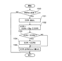
ここで、この第1の実施形態は、ACR計算部19が実行する実行セルレートACRの算出方法に特徴があり、以下、図3のフローチャートを参照しながら、この算出方法を詳述する。図3は、ACR計算部19の処理例を示すフローチャートである。
【0035】
ACR計算部19は、所定周期(例えば1セル時間)毎に図3に示す処理を開始し、まず、出側回線部12から返送されたRMセルが到来したか否かを判別する(ステップ100)。RMセルが到来していなければ、図3に示す一連の処理を終了する。
【0036】
これに対して、RMセルが到来すると、そのRMセルに係るコネクションが通信中であるか否かを、通信中フラグConnsttを参照して判別する(ステップ101)。通信中フラグConnsttは、例えば「1」が通信中を表している。例えば、入力レート計算部18において、VCS部15のコネクション毎のキューないのセル存在状況や入力レートIRによって設定される、通信中フラグConnsttの設定機能を持たせるようにしても良い。
【0037】
通信中フラグConnsttが通信中(「1」)を示していると、ACR計算部19は、到来したRMセル内の輻輳情報(レート増減表示ビットNI、輻輳表示ビットCI)などから、実行セルレートの更新候補値ACR*を算出する(ステップ102)。実行セルレートの更新候補値ACR*の計算については、例えば、ATMフォーラムの勧告であるThe ATM Forum Traffic Management Specification Version 4.0の5.10.4 Source Behaviorに従って行われる。
【0038】
このようにして求めた実行セルレートの更新候補値ACR*が、最大セルレートPCRを超えていたり、入力セルレートIRから見て速すぎたり、第2のABR制御部17が許容し得るレートとしている明示レートECRを超えていたり、ユーザに保証している最小セルレートより小さくなっていたりするなど、他のパラメータと適合しないことも多いので、ステップ103やステップ104に示す、値ACR*の適合性の判定処理を行う。
【0039】
適合性判定処理ではまず、到来したRMセル内に挿入されている、第2のABR制御部17が許容し得るレートとして算出した明示レートECR、コネクション設定時に申告された最大セルレートPCR、更新候補値ACR*、及び、その時点でのそのコネクションの入力レートIRの中から最小のものを取り出し(ステップ103)、その後、その最小値MINとコネクション設定時に申告された最小セルレートMCRとの大きいものを、最終的な実行セルレートACRに決定する(ステップ104)。このような適合性判定処理は、(1)式のように、表現することができる。
【0040】
ACR=max(MCR,min(ECR,PCR,ACR*,IR))…(1)
上述したステップ101の通信中判定で通信中でないという結果を得ると、ACR計算部19は、最終的な実行セルレートACRとして、最低セルレートLCR(Lowest Cell Rate)を設定する(ステップ105)。
【0041】
この第1の実施形態の場合、最低セルレートLCRは、ABRサービスの全てのコネクションについて共通に定められたものである。最小セルレートMCRとして申告可能な最小値より、最低セルレートLCRが小さいことが好ましい。
【0042】
到来したRMセルのコネクションが通信中であろうがなかろうが、ACR計算部19は、最終的な実行セルレートACRを決定すると、その決定した実行セルレートACRをVCS部15に与えて(ステップ106)、図3に示す一連の処理を終了する。
【0043】
以上のような処理を行うACR計算部19は、ハードウェア及びソフトウェア構成のいずれで構成されていても良い。ACR計算部19がソフトウェアで構成された場合において、図3に示したステップ101〜105の処理をプログラム的に表現すると、以下の通りである。なお、以下の表現で表された処理を実行できるのであれば、その処理の流れは図3に示したものに限定されない。
【0044】
if(Connstt=0)
ACR=LCR;
else
ACR=max(MCR,min(ECR,PCR,ACR*,IR));
VCS部15から出力されたABRサービスに係るATMセル(データセル及びRMセル)は、ATMスイッチ部12を介して交換処理されて、出側回線部12内のVPS部16に到達する。
【0045】
VPS部16は、ABRサービスに係るATMセルが到来したときには、それがデータセルであると、ABRサービス用のキュー16aにキューイングした後、ABRサービスのコネクショングループに与えられている割当帯域(セルレート)Bgに従って後段(図示せず)に送出(シェーピング)する。一方、VPS部16は、到来したABRサービスに係るATMセルがRMセルであると、そのRMセルを第2のABR制御部17に引き渡し、これにより、第2のABR制御部17は、そのRMセルの輻輳情報や明示セルレートECRなどの各種情報を盛り込んで入側回線部11に返送する。
【0046】
第2のABR制御部17によるRMセルの返送処理自体は、従来と同様であるが、図3に示したACR計算方法との関係もあるので、ECR計算部20が実行するECR計算処理を簡単に説明する。図4は、ECR計算部20が実行するECR計算処理を示すフローチャートである。
【0047】
ECR計算部20は、所定周期(例えば1セル時間)毎に図4に示す処理を開始し、まず、RMセルが到来したか否かを確認する(ステップ150)。到来していると、ECR計算部20は、そのRMセルに含まれている実行セルレートCCRi(iはコネクションを示す)を取り出す(ステップ151)。そして、ECR計算部20は、(2)式に従って、そのコネクションiの明示セルレートECRiを算出する(ステップ152)。
【0048】
ECRi=CCRi+(Bg−ΣCCR) …(2)
(2)式において、Bgは、VPS部16でABRコネクショングループに割当てられた帯域(セルレート)であり、ΣCCRは、ABRコネクショングルーブ内のCCRの総和である。
【0049】
その後、ECR計算部20は、計算で得られた明示セルレートECRiが、そのコネクションiについての最低保証の明示セルレートECR0iより小さいか否かを判別する(ステップ153)。小さい場合には、ECR計算部20は、明示セルレートECRiとして、最低保証の明示セルレートECR0iを設定する(ステップ154)。
【0050】
ここで、コネクションiについての最低保証の明示セルレートECR0iは、(3)式で表すことができる。すなわち、ABRコネクショングループの割当帯域Bgを、ABRコネクショングルーブの各コネクションの最小セルレートMCRで按分したものとして表すことができる。
【0051】
ECR0i=(MCRi/ΣMCR)*Bg …(3)
ECR計算部20は、最後に、得られた明示セルレートECRiをRMセルに書き込んで(ステップ155)、図4に示す一連の処理を終了する。
【0052】
この明示セルレートECRは、上述したように、ACR計算部19での実行セルレートACRの計算に利用される。
【0053】
(A−3)第1の実施形態の効果
第1の実施形態によれば、ABRサービスのセル送信側が、あるコネクションの実行セルレートACRを算出する際に、そのコネクションが通信中でなければ、実行セルレートACRを強制的に最低セルレートLCRにするようにしたので、ABRコネクショングループの他のコネクションに、従来より、MCR−LCR分の帯域(セルレート)を振り分けることができ、効率の良いトラフィック制御を行うことができる。
【0054】
以下、このような第1の実施形態の効果を、具体例を挙げて説明する。なお、第1の実施形態と比較する方法(以下、比較例方法と呼ぶ)を、実行セルレートACRの計算対象のコネクションが通信中であるか否かを問わず、常に、上述した(1)式に従って、実行セルレートACRを計算するものとする。
【0055】
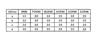
ここでは、PCR=8M(MはMbpsを表す;以下同じ)、MCR=2MのABRサービスの4本のコネクションa,b,c,dがあり、このABRサービスグループにはグループ帯域Bgとして8Mが与えられているとする。今、各コネクションa、b、c、dに、データ(データセル)が2.0Mずつ入力されている場合には、各パラメータ値は図5に示すようになる。この状態においては、このABRサービスグループには、グループ全体で8Mの帯域Bgが与えられているので、トラフィック制御上の余剰帯域は8−8(CCRの合計)=0Mである。
【0056】
この状態でコネクションdの通信が止まったとする。すなわち、コネクションdの入力セルレートIRが0Mになったとする。
【0057】
比較例方法では、通信が止まっても、実行セルレートACRは最小セルレートMCRまでしか低下しないので(ACR=MCR)、各パラメータは図6に示すようになる。このときのトラフィック制御上の余剰帯域も、8−8(CCRの合計)=0Mになり、実際には空き帯域が2M(=グループ帯域8M−IRの合計6M)あるのにも拘わらず、グループ内の他のコネクションが今以上にデータを送信しようとしても実際の空き帯域2M分を使えず、効率の良いトラフィック制御が行われていないということになる。
【0058】
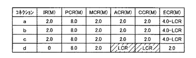
これに対して、第1の実施形態では、図5に示した状態において、コネクションdの通信が止まると(コネクションdの入力セルレートIRが0Mになると)、コネクションdの実行セルレートACRが強制的に最低セルレートLCRにするので、各パラメータは図7に示すようになる。このときのトラフィック制御上の余剰帯域は、8−(CCRの合計)=(2.0−LCR)Mになり、グループ内の他のコネクションが今以上にデータ送信しようとしたときに、この余剰帯域(2.0−LCR)Mを使って、データ送信ができるようになる。これにより、比較例方法よりも、(MCR−LCR)分の帯域を有効に使うことができるようになり、効率の良いトラフィック制御を行うことができる。
【0059】
(A−4)第1の実施形態の変形実施形態
上述した第1の実施形態の変形実施形態としては、以下のようなものを挙げることができる。
【0060】
上記説明では、実行セルレートACRに係る最低セルレートLCRとして各コネクションに共通な普遍的な固定値であるものを示したが、ABRコネクショングループの割当帯域Bgに対するグループコネクション数を考慮した所定割合に定めたりするように、コネクション数などに応じた固定値とするようにしても良い。
【0061】
また、各コネクションの最小セルレートMCRのα(0<α<1)倍を最低セルレートLCRに定めたりするように、各コネクションで異なる最低セルレートLCRを定めるようにしても良い。
【0062】
さらに、上記説明では、実行セルレートACRを強制的に最低セルレートLCRにする場合が、そのコネクションの通信が停止している場合であるものを示したが、他の場合であっても良い。例えば、そのコネクションの入力レートIRが、最小セルレートMCRのβ(0<β<1)倍より小さくなったときに、実行セルレートACRを強制的に最低セルレートLCRにするようにしても良い。
【0063】
さらにまた、上記説明では、所定条件を満たすときに実行セルレートACRを強制的に最低セルレートLCRにするという技術思想を適用したABRサービスの制御ループが、ATM交換装置の入側回線部11及び出側回線部12を結ぶ制御ループであるものを示したが、ATMネットワークシステム上の他のABRサービスの制御ループに、上記技術思想を適用することができる。
【0064】
例えば、送信端末及びATM交換装置上の仮想的な受信端末間の制御ループや、ATM交換装置上の仮想的な送信端末及び受信端末間の制御ループや、ATM交換装置上の仮想的な送信端末及び他のATM交換装置上の仮想的な受信端末間の制御ループなどに、上記技術思想を適用することができる。
【0065】
(B)第2の実施形態
次に、本発明によるセル送信装置トラフィック制御システムを、ATMネットワークシステムのATM交換装置に適用した第2の実施形態を図面を参照しながら詳述する。
【0066】
この第2の実施形態のATM交換装置も、そのトラフィック制御面から機能ブロック図化すると、第1の実施形態に係る図1で表すことができる。
【0067】
しかしながら、ACR計算部19が実行する実行セルレートACRの算出処理が第1の実施形態とは異なっている。
【0068】
そこで、以下では、第2の実施形態のACR計算部19が実行する実行セルレートACRの算出処理を、図8のフローチャートを参照しながら説明する。
【0069】
ACR計算部19は、所定周期(例えば1セル時間)毎に図8に示す処理を開始し、まず、出側回線部12から返送されたRMセルが到来したか否かを判別する(ステップ200)。RMセルが到来していなければ、図8に示す一連の処理を終了する。
【0070】
これに対して、RMセルが到来すると、ACR計算部19は、到来したRMセル内の輻輳情報(レート増減表示ビットNI、輻輳表示ビットCI)などから、実行セルレートの更新候補値ACR*を算出する(ステップ201)。ここでも、実行セルレートの更新候補値ACR*の計算については、例えば、ATMフォーラムの勧告であるThe ATM Forum Traffic Management Specification Version 4.0の5.10.4 Source Behaviorに従って行われる。
【0071】
この第2の実施形態でも、実行セルレートの更新候補値ACR*の算出後には、この値ACR*の適合性の判定処理が行われる。
【0072】
適合性判定処理ではまず、到来したRMセル内に挿入されている、第2のABR制御部17が許容し得るレートとして算出した明示レートECR、コネクション設定時に申告された最大セルレートPCR、更新候補値ACR*、及び、その時点でのそのコネクションの入力レートIRの中から最小のものを取り出し(ステップ202)、その後、その最小値MINと最低セルレートLCRとの大きいものを、最終的な実行セルレートACRに決定する(ステップ203)。このような適合性判定処理は、(4)式のように表現することができる。
【0073】
ACR=max(LCR,min(ECR,PCR,ACR*,IR))…(4)
この第2の実施形態の場合にも、最低セルレートLCRは、ABRサービスの全てのコネクションについて共通に定められたものである。第2の実施形態の場合、最低セルレートLCRは、最小セルレートMCRとして申告可能な最小値より小さい。
【0074】
ACR計算部19は、最終的な実行セルレートACRを決定すると、その決定した実行セルレートACRをVCS部15に与えて(ステップ204)、図8に示す一連の処理を終了する。
【0075】
第2の実施形態によれば、ABRサービスのセル送信側が、あるコネクションの実行セルレートACRを算出する際に、そのコネクションの入力データのレートIRが最小セルレートMCRより低いような状況などでは、実行セルレートACRとして最低セルレートLCRと入力レートIRの大きい方を選択するようにしたので、ABRコネクショングループの他のコネクションに、従来より、多くの帯域(セルレート)を振り分けることができ、効率の良いトラフィック制御を行うことができる。
【0076】
以下、このような第2の実施形態の効果を、具体例を挙げて説明する。なお、第2の実施形態と比較する方法(以下、比較例方法と呼ぶ)も、常に、上述した(1)式に従って、実行セルレートACRを計算するものとする。
【0077】
ここでも、初期状態が上述した図5に示す状態とする。この状態から、コネクションdの入力セルレートIRがその最小セルレートMCR(2M)より小さく最低セルレートLCRより大きい1Mになったとする。
【0078】
比較例方法では、この変化があっても、実行セルレートACRは最小セルレートMCRまでしか低下しないので(ACR=MCR)、各パラメータは図9に示すようになる(なお、第1の実施形態でも同様)。このときのトラフィック制御上の余剰帯域は、8−7(CCRの合計)=1Mになり、実際には空き帯域が1Mあるのにも拘わらず、グループ内の他のコネクションが今以上にデータを送信しようとしても実際の空き帯域1M分を使えず、効率の良いトラフィック制御が行われていないということができる。
【0079】
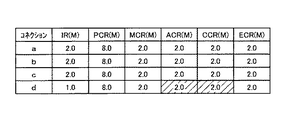
これに対して、第2の実施形態の場合、コネクションdの入力レートIRが最小セルレートMCR(2M)より小さい1Mになると、各パラメータは図10に示すようになる。すなわち、第2の実施形態では、実行セルレートACRは1M(=1M)になるので、コネクション管理上の余剰帯域は8−7(CCRの合計)=1Mになり、実際の空き帯域1M(=グループ帯域8M−IRの合計7M)を他のコネクションが、有効に使えるようになった。さらに言い換えると、入力レートIRが最小セルレートMCRより小さくても、最低セルレートLCRより大きいときには、入力レートIRに応じて連続的に実行セルレートACRを決めており、今までよりも効率よく、かつよりデータの入力レートに応じたリアルタイムなトラフィック制御を実行ができる。
【0080】
なお、入力レートIRが最低セルレートLCR以下になっても、そのときの実行セルレートACRは、最低セルレートLCRになって、そのコネクションの帯域は継続して確保されており、入力レートの増大時に直ちに応じられる。
【0081】
因みに、第2の実施形態の場合、最小セルレートMCRが実行セルレートACRの決定に直接は関係していないが、ユーザは、通信中においては、申告した最小セルレートを超えてデータ(データセル)を送信することがほとんどであり、上述した第2の実施形態の効果が発揮されることはまれであり、実行セルレートACRの決定に最小セルレートMCRを直接反映させなくても問題となることは生じない。むしろ、入力レートIRが最小セルレートMCR以下になっている状況で、実行セルレートACRを最小セルレートMCRにすることのほうが問題が大きい。
【0082】
上述した第2の実施形態の変形実施形態としては、以下のようなものを挙げることができる。
【0083】
上記説明では、実行セルレートACRに係る最低セルレートLCRとして各コネクションに共通な普遍的な固定値であるものを示したが、ABRコネクショングループの割当帯域Bgに対するグループコネクション数を考慮した所定割合に定めたりするように、コネクション数などに応じた固定値とするようにしても良い。また、各コネクションの最小セルレートMCRのα(0<α<1)倍を最低セルレートLCRに定めたりするように、各コネクションで異なる最低セルレートLCRを定めるようにしても良い。
【0084】
さらにまた、第2の実施形態の技術思想を、例えば、送信端末及びATM交換装置上の仮想的な受信端末間の制御ループや、ATM交換装置上の仮想的な送信端末及び受信端末間の制御ループや、ATM交換装置上の仮想的な送信端末及び他のATM交換装置上の仮想的な受信端末間の制御ループなどに適用することができる。
【0085】
(C)他の実施形態
上記各実施形態では、ATM交換装置において、ATMスイッチ部13に対する入側回線部11と出力回線部12とが1:1のものを示したが、複数:1や、1:複数や、複数:複数でも同様に適用できる。また、ABRサービス専用のATM交換装置にも、本発明を適用できる。
【0086】
また、上記第1の実施形態の技術思想と、上記第2の実施形態の技術思想とを組み合わせても良い。例えば、第1の実施形態に係る最低セルレートをLCR1とし、第2の実施形態に係る最低セルレートをLCR2(>LCR1)とし、コネクションが通信していないときには、実行セルレートACRを最低セルレートLCR1にし、コネクションが通信しているときには、最低セルレートをLCR2とした上述した(4)式に従って、実行セルレートACRを定めるようにしても良い。
【0087】
本発明の技術思想の適用サービスは、ABRサービスに限定されるものでなく、実行セルレートの決定(下側制限方法)がABRサービスと同様なサービスに対しても適用可能である。また、ネットワークも、ATMネットワークに限定されない。
【0088】
【発明の効果】
本発明によれば、あるコネクションのデータセルの入力レートが最小セルレートより小さい場合において、所定条件下で、データセルを送り出す実行セルレートを、最小セルレートより小さい最低セルレートにするようにしたので、他のコネクションに振り分けられるレートを大きくでき、効率の良いトラフィック制御を実現できる。
【図面の簡単な説明】
【図1】第1の実施形態のATM交換装置のトラフィック制御構成を示すブロック図である。
【図2】従来のABRサービスに係るトラフィック制御方法の説明図である。
【図3】第1の実施形態のACR計算処理を示すフローチャートである。
【図4】第1の実施形態のECR計算処理を示すフローチャートである。
【図5】第1の実施形態の効果の説明図(1)である。
【図6】第1の実施形態の効果の説明図(2)である。
【図7】第1の実施形態の効果の説明図(3)である。
【図8】第2の実施形態のACR計算処理を示すフローチャートである。
【図9】第2の実施形態の効果の説明図(1)である。
【図10】第2の実施形態の効果の説明図(2)である。
【符号の説明】
10…ATM交換装置、11…入側回線部、12…出側回線部、13…ATMスイッチ部(SW部)、14…第1のABR制御部、17…第2のABR制御部、18…入力レート計算部、19…ACR計算部、20…ECR計算部。[0001]
BACKGROUND OF THE INVENTION
The present invention relates to a cell transmission device and a traffic control system, and is suitable for traffic control using an ABR (Available Bit Rate) service in an ATM (Asynchronous Transfer Mode) network system, for example.
[0002]
[Prior art]
In the ATM network system, in order to cope with various services required for the type of data to be handled (voice data, image data, other data, and combinations of these data), the user is characterized by the data he / she places on the ATM network Select the optimal service category.
[0003]
One of the service categories provided by the ATM network system is an ABR service.
[0004]
The ABR service guarantees communication quality that exceeds the MCR (Minimum Cell Rate), which is the minimum service rate declared and negotiated at the time of call connection, and is declared and negotiated at the time of call connection if there is room in network resources. It is a service that provides communication at a speed equal to or less than the PCR (Peak Cell Rate), which is the maximum rate of the mobile phone.
[0005]
In order to dynamically increase / decrease the transmission rate of the transmitting terminal up to the maximum rate PCR depending on the network resource status, a traffic control cell called a resource management cell (RM cell) is slightly removed between the transmitting terminal and the receiving terminal. To provide an ABR service.
[0006]
In the ABR service, a forward RM cell (FRM cell; hereinafter referred to as a forward control cell) is transmitted in the forward direction every time a predetermined number of data cells (information cells) are transmitted from the transmitting terminal. When the receiving terminal receives the forward control cell, it transmits it as a backward RM cell (BRM cell; hereinafter referred to as reverse control cell) in the reverse direction toward the transmitting terminal. At this time, the receiving terminal adds the congestion information of the network obtained by reception of the forward data cell to the backward control cell and transmits it. In addition, when a reverse control cell passes through a device such as an ATM switch on the way, a rate that the device can accept may be explicitly written to the reverse control cell by the device. The transmitting terminal receives the reverse control cell, identifies the congestion state of the network, and controls the transmission rate.
[0007]
Here, the ATM switching apparatus performs the operations of the transmitting terminal and the receiving terminal described above, thereby dividing the feedback loop (control loop) of the ABR service into a plurality of control loops, and reducing one control loop. Traffic control that immediately reflects the state of the system. An ATM switching apparatus (ATM switch) that virtually acts as a transmitting terminal and a receiving terminal in such an ABR service is called VD / VS (Virtual Destination / Virtual Source).
[0008]
In the ABR service in the ATM network system, the cell rate allowed for the terminal can be changed at any time using the RM cell or the congestion instruction bit in accordance with the traffic state in the ATM switching apparatus of the network or in the network.
[0009]
FIG. 2 is a simple conceptual diagram of a traffic control method in the ABR service. FIG. 2 shows an example in which one ATM switching apparatus 3 is interposed in communication from the transmission terminal 1 to the reception terminal 2.
[0010]
In FIG. 2, the transmission terminal 1 transmits one forward control cell FRM every time N data cells DC are transmitted. The receiving terminal 2 receives the forward control cell FRM together with the data cell DC. The receiving terminal 2 rewrites the data in the forward control cell FRM and returns the backward control cell BRM to the transmitting terminal 1.
[0011]
Such RM cell management is possible not only between the original transmitting terminal 1 and the receiving terminal 2, but also in VS (virtual transmitting terminal) and VD (virtual receiving terminal). . For example, VS and VD are mounted on the ATM switching apparatus 3 and the control loop of the ABR service is divided into a plurality of loops. The ATM switching device 3 functions as a VD (virtual receiving terminal) when viewed from the transmitting terminal 1 and functions as a VS (virtual transmitting terminal) when viewed from the receiving terminal 2.
[0012]
When congestion occurs in the local exchange, the ATM switching apparatus 3 notifies the subsequent network of the congestion by setting the congestion display bit CI of the forward control cell FRM passing therethrough as congestion. Receiving this, the receiving terminal 2 rewrites the DIR bit indicating the directionality to the instruction (DIR = 1) related to the reverse direction control cell BRM and returns it to the transmitting side.
[0013]
Further, when congestion occurs, the ATM switching device 3 rewrites the allowable cell rate (explicit cell rate) ECR in the backward control cell BRM to an explicitly small value. When receiving the reverse direction control cell BRM, the transmission terminal 1 changes the transmission cell rate (expressed as an execution cell rate in the embodiment) according to the congestion indication bit CI. Here, when the congestion indication bit CI indicates that there is congestion, the transmission cell rate is decreased, and when it indicates that there is no congestion, the transmission cell rate is increased within a range not exceeding the declared maximum cell rate PCR. When the allowable cell rate ECR is smaller than the current cell rate, the transmission cell rate is set to be equal to or lower than the allowable cell rate ECR. When the allowable cell rate ECR is smaller than the reported minimum cell rate MCR, the transmission cell rate becomes the reported minimum cell rate MCR.
[0014]
Similar processing is performed when the ATM switching apparatus 3 operates as a virtual transmission terminal.
[0015]
As described above, the transmission side determines the next transmission cell rate in consideration of various parameters such as data cell input information and information in the backward control cell BRM.
[0016]
[Problems to be solved by the invention]
In the conventional traffic control method, even when the data input rate is smaller than the declared minimum cell rate MCR, the data transmission cell rate does not fall below the declared minimum cell rate MCR. As a result, an extra free bandwidth for (MCR-input rate) is continuously reserved, and the free bandwidth cannot be allocated to other connections belonging to the ABR connection group, so that efficient traffic control cannot be performed.
[0017]
Therefore, there is a demand for a cell transmission device and a traffic control system that can perform efficient traffic control.
[0018]
[Means for Solving the Problems]
In order to solve such a problem, the first aspect of the present invention provides a cell transmitting apparatus that declares a minimum cell rate for each connection, and transmits a data cell for each connection according to the determined execution cell rate for each connection. 1) input rate calculation means for obtaining the input rate of each connection based on the input state of the data cell to the cell transmitting apparatus; and (2) for cell rate update given from at least the opposite cell receiving apparatus for each connection. The effective cell rate is updated according to the information and the input rate, and the minimum cell rate that is lower than the minimum cell rate is updated under a predetermined condition where the input rate is lower than the minimum cell rate. And having an execution cell rate update means And butterflies.
[0019]
In addition, according to the second aspect of the present invention, a minimum cell rate is declared for each connection, and for each connection, a cell transmission device that transmits a data cell of each connection according to the determined execution cell rate, and to the cell transmission device Then, in a traffic control system including a cell reception device that transmits information for rate update necessary for updating the effective cell rate, the cell transmission device according to the first aspect of the present invention is applied. .
[0020]
DETAILED DESCRIPTION OF THE INVENTION
(A) First embodiment
Hereinafter, a first embodiment in which a cell transmission device and a traffic control system according to the present invention are applied to an ATM switching device of an ATM network system will be described in detail with reference to the drawings.
[0021]
(A-1) Configuration of the first embodiment
FIG. 1 is a block diagram showing a traffic control configuration based on the ABR service of the ATM switching apparatus 10 according to the first embodiment.
[0022]
FIG. The ATM switching apparatus 10 includes an incoming line unit 11, an ATM switch unit (SW unit) 13, and an
[0023]
Here, the first
[0024]
The input
[0025]
The
[0026]
In the
[0027]
The
[0028]
The VPS unit 16 in the
[0029]
The second ABR control unit 17 incorporates predetermined information into the RM cell given from the ingress line unit 11 (including changes) and returns it to the ingress line unit 11. The second ABR control unit 17 includes each unit that manipulates information of the RM cell, but also includes an
[0030]
(A-2) Operation of the first embodiment
Next, a traffic control operation related to the ABR service in the ATM switching apparatus 10 having the above configuration will be described.
[0031]
In the incoming line unit 11, the incoming input data cell is given to the
[0032]
Also, the input rate IR for each connection is constantly calculated by the input
[0033]
The
[0034]
Here, this first embodiment is characterized by a method of calculating the effective cell rate ACR executed by the
[0035]
The
[0036]
On the other hand, when an RM cell arrives, it is determined whether or not the connection related to the RM cell is in communication with reference to the communication flag Connst (step 101). For example, “1” indicates that the communication is in progress. For example, the input
[0037]
When the communication flag Connst indicates that communication is in progress (“1”), the
[0038]
The execution cell rate update candidate value ACR * determined in this way exceeds the maximum cell rate PCR, is too fast as viewed from the input cell rate IR, or is an explicit rate that is allowed by the second ABR control unit 17 Since there are many cases where it does not conform to other parameters such as exceeding the ECR or smaller than the minimum cell rate guaranteed to the user, the conformity determination processing of the value ACR * shown in
[0039]
In the suitability determination process, first, the explicit rate ECR calculated as an acceptable rate by the second ABR control unit 17 inserted in the incoming RM cell, the maximum cell rate PCR declared at the time of connection setting, and the update candidate value The smallest one is taken out from ACR * and the input rate IR of the connection at that time (step 103), and then the largest one of the minimum value MIN and the minimum cell rate MCR declared at the time of connection setting is obtained. The final effective cell rate ACR is determined (step 104). Such suitability determination processing can be expressed as in equation (1).
[0040]
ACR = max (MCR, min (ECR, PCR, ACR *, IR)) (1)
If the result of the determination during communication in
[0041]
In the case of the first embodiment, the minimum cell rate LCR is determined in common for all connections of the ABR service. The minimum cell rate LCR is preferably smaller than the minimum value that can be reported as the minimum cell rate MCR.
[0042]
Whether or not the incoming RM cell connection is in communication, the
[0043]
The
[0044]
if (Connstt = 0)
ACR = LCR;
else
ACR = max (MCR, min (ECR, PCR, ACR *, IR));
The ATM cell (data cell and RM cell) related to the ABR service output from the
[0045]
When an ATM cell related to the ABR service arrives, the VPS unit 16 queues it in the
[0046]
RM cell return processing by the second ABR control unit 17 Body Although it is the same as that of the prior art, it also has a relationship with the ACR calculation method shown in FIG. FIG. 4 is a flowchart showing an ECR calculation process executed by the
[0047]
The
[0048]
ECRi = CCRi + (Bg−ΣCCR) (2)
In the equation (2), Bg is a band (cell rate) assigned to the ABR connection group by the VPS unit 16, and ΣCCR is a sum of CCRs in the ABR connection group.
[0049]
Thereafter, the
[0050]
Here, the minimum guaranteed explicit cell rate ECR0i for connection i can be expressed by equation (3). That is, the allocated bandwidth Bg of the ABR connection group can be expressed as being prorated by the minimum cell rate MCR of each connection of the ABR connection group.
[0051]
ECR0i = (MCRi / ΣMCR) * Bg (3)
Finally, the
[0052]
This explicit cell rate ECR is used for calculation of the effective cell rate ACR in the
[0053]
(A-3) Effects of the first embodiment
According to the first embodiment, when the cell transmitting side of the ABR service calculates the effective cell rate ACR of a certain connection, if the connection is not in communication, the effective cell rate ACR is forcibly set to the lowest cell rate LCR. Therefore, a band (cell rate) for MCR-LCR can be allocated to other connections of the ABR connection group, and efficient traffic control can be performed.
[0054]
Hereinafter, the effect of the first embodiment will be described with a specific example. Note that the method of comparing with the first embodiment (hereinafter referred to as “comparative method”) is always the above-described equation (1) regardless of whether the connection subject to calculation of the effective cell rate ACR is in communication. The effective cell rate ACR is calculated according to
[0055]
Here, there are four connections a, b, c, and d of ABR service with PCR = 8M (M represents Mbps; the same applies hereinafter) and MCR = 2M, and this ABR service group has 8M as a group bandwidth Bg. Suppose you are given. When 2.0 M of data (data cells) are input to each of the connections a, b, c, and d, the parameter values are as shown in FIG. In this state, since this ABR service group is provided with a band Bg of 8M for the entire group, the surplus bandwidth for traffic control is 8-8 (total CCR) = 0M.
[0056]
Assume that communication of connection d stops in this state. That is, it is assumed that the input cell rate IR of the connection d becomes 0M.
[0057]
In the comparative example method, even if communication stops, the effective cell rate ACR decreases only to the minimum cell rate MCR (ACR = MCR), so each parameter is as shown in FIG. The surplus bandwidth in traffic control at this time is also 8-8 (total of CCR) = 0M, and actually there is a free bandwidth of 2M (= total of the group bandwidth of 8M-IR is 6M). Even if another connection in the network tries to transmit data more than it is, the actual free bandwidth of 2M cannot be used, and efficient traffic control is not performed.
[0058]
On the other hand, in the first embodiment, when the communication of the connection d stops in the state shown in FIG. 5 (when the input cell rate IR of the connection d becomes 0M), the execution cell rate ACR of the connection d is forcibly set. Since the minimum cell rate LCR is set, each parameter is as shown in FIG. The surplus bandwidth in traffic control at this time is 8− (total CCR) = (2.0−LCR) M, and this surplus when another connection in the group tries to transmit data more than now. Data can be transmitted using the band (2.0-LCR) M. As a result, the bandwidth corresponding to (MCR-LCR) can be used more effectively than the comparative example method, and efficient traffic control can be performed.
[0059]
(A-4) Modified embodiment of the first embodiment
The following can be mentioned as modified embodiments of the first embodiment described above.
[0060]
In the above description, the lowest cell rate LCR related to the effective cell rate ACR is a universal fixed value common to each connection. However, the minimum cell rate LCR may be set to a predetermined ratio in consideration of the number of group connections with respect to the allocated bandwidth Bg of the ABR connection group. As described above, a fixed value may be set according to the number of connections.
[0061]
Further, a different minimum cell rate LCR may be determined for each connection so that α (0 <α <1) times the minimum cell rate MCR of each connection is determined as the minimum cell rate LCR.
[0062]
Further, in the above description, the case where the effective cell rate ACR is forcibly set to the lowest cell rate LCR is a case where communication of the connection is stopped, but other cases may be used. For example, when the input rate IR of the connection becomes smaller than β (0 <β <1) times the minimum cell rate MCR, the effective cell rate ACR may be forcibly set to the lowest cell rate LCR.
[0063]
Furthermore, in the above description, the control loop of the ABR service to which the execution cell rate ACR is forcibly set to the minimum cell rate LCR when a predetermined condition is satisfied is represented by the ingress line unit 11 and the egress side of the ATM switching apparatus. Although the control loop connecting the
[0064]
For example, a control loop between a transmission terminal and a virtual reception terminal on an ATM switching apparatus, a control loop between a virtual transmission terminal and a reception terminal on an ATM switching apparatus, or a virtual transmission terminal on an ATM switching apparatus And the above technical idea can be applied to a control loop between virtual receiving terminals on other ATM switching devices.
[0065]
(B) Second embodiment
Next, a second embodiment in which the cell transmission apparatus traffic control system according to the present invention is applied to an ATM switching apparatus of an ATM network system will be described in detail with reference to the drawings.
[0066]
The ATM switching apparatus according to the second embodiment can also be represented by FIG. 1 according to the first embodiment, if the function block diagram is formed from the traffic control side.
[0067]
However, the execution cell rate ACR calculation process executed by the
[0068]
Therefore, in the following, an execution cell rate ACR calculation process executed by the
[0069]
The
[0070]
On the other hand, when the RM cell arrives, the
[0071]
Also in the second embodiment, after the update candidate value ACR * for the execution cell rate is calculated, the suitability determination process for this value ACR * is performed.
[0072]
In the suitability determination process, first, the explicit rate ECR calculated as an acceptable rate by the second ABR control unit 17 inserted in the incoming RM cell, the maximum cell rate PCR declared at the time of connection setting, and the update candidate value The smallest one is extracted from ACR * and the input rate IR of the connection at that time (step 202), and then the largest of the minimum value MIN and the lowest cell rate LCR is obtained as the final execution cell rate ACR. (Step 203). Such suitability determination processing can be expressed as in equation (4).
[0073]
ACR = max (LCR, min (ECR, PCR, ACR *, IR)) (4)
Also in the case of the second embodiment, the minimum cell rate LCR is determined in common for all connections of the ABR service. In the case of the second embodiment, the minimum cell rate LCR is smaller than the minimum value that can be declared as the minimum cell rate MCR.
[0074]
When the final effective cell rate ACR is determined, the
[0075]
According to the second embodiment, when the cell transmitting side of the ABR service calculates the effective cell rate ACR of a certain connection, in the situation where the rate IR of the input data of the connection is lower than the minimum cell rate MCR, the effective cell rate Since the one with the lowest cell rate LCR and input rate IR is selected as the ACR, more bandwidth (cell rate) can be allocated to other connections of the ABR connection group, and efficient traffic control can be performed. It can be carried out.
[0076]
Hereinafter, the effect of the second embodiment will be described with a specific example. Note that the method to be compared with the second embodiment (hereinafter referred to as “comparative example method”) always calculates the effective cell rate ACR according to the above-described equation (1).
[0077]
Again, the initial state is the state shown in FIG. From this state, it is assumed that the input cell rate IR of the connection d is 1M which is smaller than the minimum cell rate MCR (2M) and larger than the minimum cell rate LCR.
[0078]
In the comparative example method, even if this change occurs, the effective cell rate ACR decreases only to the minimum cell rate MCR (ACR = MCR), so each parameter is as shown in FIG. 9 (the same applies to the first embodiment). ). At this time, the surplus bandwidth for traffic control is 8-7 (total of CCR) = 1M, and although there is actually 1M of free bandwidth, other connections in the group receive more data than now. Even if transmission is attempted, the actual free bandwidth of 1M cannot be used, and it can be said that efficient traffic control is not performed.
[0079]
On the other hand, in the case of the second embodiment, when the input rate IR of the connection d becomes 1M which is smaller than the minimum cell rate MCR (2M), the parameters are as shown in FIG. That is, in the second embodiment, since the effective cell rate ACR is 1M (= 1M), the surplus bandwidth in connection management is 8-7 (total CCR) = 1M, and the actual free bandwidth 1M (= group) Bandwidth 8M-IR (7M in total) can be used effectively by other connections. In other words, even if the input rate IR is smaller than the minimum cell rate MCR, when the input cell rate IR is larger than the minimum cell rate LCR, the effective cell rate ACR is continuously determined according to the input rate IR, and more efficient than before and more data. Real-time traffic control according to the input rate can be executed.
[0080]
Even if the input rate IR becomes equal to or lower than the minimum cell rate LCR, the effective cell rate ACR at that time becomes the minimum cell rate LCR, and the bandwidth of the connection is continuously secured, and immediately responds when the input rate increases. It is done.
[0081]
In the case of the second embodiment, the minimum cell rate MCR is not directly related to the determination of the effective cell rate ACR, but the user transmits data (data cell) exceeding the declared minimum cell rate during communication. In most cases, the effects of the second embodiment described above are rarely exhibited, and there is no problem even if the minimum cell rate MCR is not directly reflected in the determination of the effective cell rate ACR. Rather, when the input rate IR is less than or equal to the minimum cell rate MCR, it is more problematic to set the effective cell rate ACR to the minimum cell rate MCR.
[0082]
As modifications of the second embodiment described above, the following may be mentioned.
[0083]
In the above description, the lowest cell rate LCR related to the effective cell rate ACR is a universal fixed value common to each connection. However, the minimum cell rate LCR may be set to a predetermined ratio in consideration of the number of group connections with respect to the allocated bandwidth Bg of the ABR connection group. As described above, a fixed value may be set according to the number of connections. Further, a different minimum cell rate LCR may be determined for each connection so that α (0 <α <1) times the minimum cell rate MCR of each connection is determined as the minimum cell rate LCR.
[0084]
Furthermore, the technical idea of the second embodiment is, for example, a control loop between a transmission terminal and a virtual reception terminal on the ATM switching apparatus, or a control between a virtual transmission terminal and a reception terminal on the ATM switching apparatus. The present invention can be applied to a loop or a control loop between a virtual transmission terminal on an ATM switching apparatus and a virtual reception terminal on another ATM switching apparatus.
[0085]
(C) Other embodiments
In each of the above embodiments, in the ATM switching apparatus, the ingress line unit 11 and the
[0086]
The technical idea of the first embodiment and the technical idea of the second embodiment may be combined. For example, the lowest cell rate according to the first embodiment is LCR1, the lowest cell rate according to the second embodiment is LCR2 (> LCR1), and when the connection is not communicating, the effective cell rate ACR is set to the lowest cell rate LCR1, and the connection , The effective cell rate ACR may be determined according to the above-described equation (4) where the minimum cell rate is LCR2.
[0087]
The application service of the technical idea of the present invention is not limited to the ABR service, and can also be applied to a service whose execution cell rate is determined (lower limit method) similar to the ABR service. Further, the network is not limited to the ATM network.
[0088]
【The invention's effect】
According to the present invention, when the input rate of the data cell of a certain connection is smaller than the minimum cell rate, the execution cell rate for sending out the data cell under a predetermined condition is set to the lowest cell rate smaller than the minimum cell rate. The rate allocated to the connection can be increased, and efficient traffic control can be realized.
[Brief description of the drawings]
FIG. 1 is a block diagram showing a traffic control configuration of an ATM switching apparatus according to a first embodiment.
FIG. 2 is an explanatory diagram of a traffic control method according to a conventional ABR service.
FIG. 3 is a flowchart showing ACR calculation processing according to the first embodiment;
FIG. 4 is a flowchart illustrating an ECR calculation process according to the first embodiment.
FIG. 5 is an explanatory diagram (1) of an effect of the first embodiment.
FIG. 6 is an explanatory diagram (2) of an effect of the first embodiment.
FIG. 7 is an explanatory diagram (3) of an effect of the first embodiment.
FIG. 8 is a flowchart illustrating ACR calculation processing according to the second embodiment;
FIG. 9 is an explanatory diagram (1) of an effect of the second embodiment.
FIG. 10 is an explanatory diagram (2) of an effect of the second embodiment.
[Explanation of symbols]
DESCRIPTION OF SYMBOLS 10 ... ATM switching apparatus, 11 ... Incoming line part, 12 ... Outgoing line part, 13 ... ATM switch part (SW part), 14 ... 1st ABR control part, 17 ... 2nd ABR control part, 18 ... Input rate calculation unit, 19... ACR calculation unit, 20... ECR calculation unit.
Claims (6)
当該セル送信装置へのデータセルの入力状況に基づいて、各コネクションの入力レートを得る入力レート計算手段と、
各コネクションについて、少なくとも対向するセル受信装置から与えられたセルレート更新用情報、及び、上記入力レートに応じて、上記実行セルレートを更新するものであって、上記入力レートが上記最小セルレートより小さい所定条件下で、上記最小セルレートより小さい最低セルレートを、更新した上記実行セルレートにする実行セルレート更新手段と
を有することを特徴とするセル送信装置。In the cell transmission device that transmits the data cell of each connection according to the determined execution cell rate for each connection, the minimum cell rate is declared for each connection.
Based on the input state of the data cell to the cell transmitter, input rate calculation means for obtaining the input rate of each connection,
For each connection, at least the cell rate update information given from the opposite cell receiver and the input cell rate are updated, and the input cell rate is lower than the minimum cell rate. A cell transmitting apparatus comprising: an execution cell rate updating unit that changes a minimum cell rate smaller than the minimum cell rate to the updated execution cell rate.
上記セル送信装置として、請求項1〜4のいずれかに記載のものを適用したことを特徴とするトラフィック制御システム。A minimum cell rate is declared for each connection, and for each connection, a cell transmitter that transmits data cells of each connection according to the determined effective cell rate, and for updating the effective cell rate for this cell transmitter In a traffic control system including a cell receiver that transmits rate update information,
5. A traffic control system according to claim 1, wherein the cell transmission device is one according to any one of claims 1 to 4.
Priority Applications (2)
| Application Number | Priority Date | Filing Date | Title |
|---|---|---|---|
| JP2000179261A JP4239367B2 (en) | 2000-06-15 | 2000-06-15 | Cell transmission device and traffic control system |
| US09/877,004 US6859436B2 (en) | 2000-06-15 | 2001-06-11 | Bandwidth control method, cell transmitting apparatus, and traffic control system |
Applications Claiming Priority (1)
| Application Number | Priority Date | Filing Date | Title |
|---|---|---|---|
| JP2000179261A JP4239367B2 (en) | 2000-06-15 | 2000-06-15 | Cell transmission device and traffic control system |
Publications (2)
| Publication Number | Publication Date |
|---|---|
| JP2001358728A JP2001358728A (en) | 2001-12-26 |
| JP4239367B2 true JP4239367B2 (en) | 2009-03-18 |
Family
ID=18680561
Family Applications (1)
| Application Number | Title | Priority Date | Filing Date |
|---|---|---|---|
| JP2000179261A Expired - Fee Related JP4239367B2 (en) | 2000-06-15 | 2000-06-15 | Cell transmission device and traffic control system |
Country Status (2)
| Country | Link |
|---|---|
| US (1) | US6859436B2 (en) |
| JP (1) | JP4239367B2 (en) |
Families Citing this family (7)
| Publication number | Priority date | Publication date | Assignee | Title |
|---|---|---|---|---|
| JP4158319B2 (en) * | 2000-06-15 | 2008-10-01 | 沖電気工業株式会社 | Cell receiving apparatus and traffic control system |
| CA2387654A1 (en) * | 2002-05-24 | 2003-11-24 | Alcatel Canada Inc. | Partitioned interface architecture for transmission of broadband network traffic to and from an access network |
| US8090374B2 (en) * | 2005-12-01 | 2012-01-03 | Quantenna Communications, Inc | Wireless multimedia handset |
| US20070136446A1 (en) * | 2005-12-01 | 2007-06-14 | Behrooz Rezvani | Wireless media server system and method |
| WO2007127332A2 (en) * | 2006-04-26 | 2007-11-08 | Bittorrent, Inc. | End-system dynamic rate limiting of background traffic |
| WO2009024188A1 (en) * | 2007-08-22 | 2009-02-26 | Telefonaktiebolaget Lm Ericsson (Publ) | Data transmission control |
| US7995476B2 (en) * | 2008-12-04 | 2011-08-09 | Microsoft Corporation | Bandwidth allocation algorithm for peer-to-peer packet scheduling |
Family Cites Families (13)
| Publication number | Priority date | Publication date | Assignee | Title |
|---|---|---|---|---|
| GB9602027D0 (en) * | 1996-02-01 | 1996-04-03 | Madge Networks Ltd | Flow control in a cell switched communication system |
| US5987031A (en) * | 1997-05-22 | 1999-11-16 | Integrated Device Technology, Inc. | Method for fair dynamic scheduling of available bandwidth rate (ABR) service under asynchronous transfer mode (ATM) |
| US6252847B1 (en) * | 1997-09-12 | 2001-06-26 | Alcatel Canada Inc. | Calculation of quotient-based explicit rate algorithm for ABR traffic |
| EP0903894A1 (en) * | 1997-09-18 | 1999-03-24 | Alcatel | Method and device to characterize cell traffic |
| US6377550B1 (en) * | 1997-10-28 | 2002-04-23 | Texas Instruments Incorporated | Nested measurement period switch algorithm for flow control of available bit rate ATM communications |
| JPH11275097A (en) * | 1998-03-20 | 1999-10-08 | Fujitsu Ltd | Network system |
| US6597662B1 (en) * | 1998-03-24 | 2003-07-22 | Nortel Networks Limited | Apparatus and method for optimizing max-min fair rate control in ABR sessions |
| JP3474439B2 (en) * | 1998-05-08 | 2003-12-08 | 富士通株式会社 | Communication control device having ABR communication service function and ATM exchange having this communication control device |
| US6331970B1 (en) * | 1998-12-28 | 2001-12-18 | Nortel Networks Limited | Dynamic generic cell rate algorithm for policing ABR traffic |
| US6442140B1 (en) * | 1999-01-04 | 2002-08-27 | 3Com Corporation | Method for automatic setup of missing RM cell count parameter CRM in an ATM traffic management descriptor |
| US6512743B1 (en) * | 1999-04-15 | 2003-01-28 | Cisco Technology, Inc. | Bandwidth allocation for ATM available bit rate service |
| US6466541B1 (en) * | 2000-05-31 | 2002-10-15 | Fujitsu Network Communications, Inc. | Cell pacing on a network link employing a rate-based flow control protocol with underlying credit-based flow control mechanisms |
| US6452903B1 (en) * | 2000-05-31 | 2002-09-17 | Fujitsu Network Communications, Inc. | Network switch supporting rate-based and credit-based flow control mechanisms on a link-by-link basis |
-
2000
- 2000-06-15 JP JP2000179261A patent/JP4239367B2/en not_active Expired - Fee Related
-
2001
- 2001-06-11 US US09/877,004 patent/US6859436B2/en not_active Expired - Lifetime
Also Published As
| Publication number | Publication date |
|---|---|
| US6859436B2 (en) | 2005-02-22 |
| US20010053127A1 (en) | 2001-12-20 |
| JP2001358728A (en) | 2001-12-26 |
Similar Documents
| Publication | Publication Date | Title |
|---|---|---|
| EP0873037B1 (en) | Traffic shaper for ATM network using dual leaky bucket regulator | |
| US6512745B1 (en) | Packet switching network, packet switching equipment, and network management equipment | |
| US6687228B1 (en) | Method and system in a packet switching network for dynamically sharing the bandwidth of a virtual path connection among different types of connections | |
| US6690678B1 (en) | Method and system in a packet switching network for dynamically adjusting the bandwidth of a continuous bit rate virtual path connection according to the network load | |
| US6594265B1 (en) | Method and system in an asynchronous transfer mode (ATM) network for providing an available bit rate interface to a continuous bit rate virtual path connection with adjustable bandwidth | |
| US8009565B2 (en) | Switch with function for assigning queue based on a declared transfer rate | |
| JP3623089B2 (en) | Method for transmitting cells in asynchronous transfer mode | |
| JPH0856222A (en) | Traffic control system | |
| JP3262029B2 (en) | Cell transmission switch call connection control device | |
| US6587436B1 (en) | Method and apparatus for allocation of available bandwidth | |
| JP4239367B2 (en) | Cell transmission device and traffic control system | |
| JP4158319B2 (en) | Cell receiving apparatus and traffic control system | |
| Muddu et al. | Max-min rate control algorithm for available bit rate service in atm networks | |
| JPH1084345A (en) | Cell rate monitor for abr | |
| JP3261057B2 (en) | ATM switch and call admission priority control method | |
| EP0884923B1 (en) | Packet switching network, packet switching equipment, and network management equipment | |
| Nikloaidis et al. | A bibliography on performance issues ATM networks | |
| US6542509B1 (en) | Virtual path level fairness | |
| JPH11331169A (en) | Communication control equipment having abr communication service function and atm exchange having the same | |
| JP2845352B2 (en) | Call admission control device for exchange in ATM network | |
| Goyal et al. | Modeling traffic management in ATM networks with OPNET | |
| KR100297859B1 (en) | Method for supporting guaranteed frame rate in atm | |
| Murthy | A Software Emulation and Evaluation of Available Bit Rate Service | |
| JPH11275099A (en) | Point-to-multipoint abr connection setting control system | |
| Thuy et al. | Bandwidth allocation based on declared UPC parameters in ATM networks |
Legal Events
| Date | Code | Title | Description |
|---|---|---|---|
| A621 | Written request for application examination |
Free format text: JAPANESE INTERMEDIATE CODE: A621 Effective date: 20060731 |
|
| A977 | Report on retrieval |
Free format text: JAPANESE INTERMEDIATE CODE: A971007 Effective date: 20080529 |
|
| A131 | Notification of reasons for refusal |
Free format text: JAPANESE INTERMEDIATE CODE: A131 Effective date: 20080617 |
|
| A521 | Request for written amendment filed |
Free format text: JAPANESE INTERMEDIATE CODE: A523 Effective date: 20080801 |
|
| TRDD | Decision of grant or rejection written | ||
| A01 | Written decision to grant a patent or to grant a registration (utility model) |
Free format text: JAPANESE INTERMEDIATE CODE: A01 Effective date: 20081202 |
|
| A01 | Written decision to grant a patent or to grant a registration (utility model) |
Free format text: JAPANESE INTERMEDIATE CODE: A01 |
|
| A61 | First payment of annual fees (during grant procedure) |
Free format text: JAPANESE INTERMEDIATE CODE: A61 Effective date: 20081215 |
|
| FPAY | Renewal fee payment (event date is renewal date of database) |
Free format text: PAYMENT UNTIL: 20120109 Year of fee payment: 3 |
|
| R150 | Certificate of patent or registration of utility model |
Free format text: JAPANESE INTERMEDIATE CODE: R150 |
|
| FPAY | Renewal fee payment (event date is renewal date of database) |
Free format text: PAYMENT UNTIL: 20120109 Year of fee payment: 3 |
|
| S531 | Written request for registration of change of domicile |
Free format text: JAPANESE INTERMEDIATE CODE: R313531 |
|
| FPAY | Renewal fee payment (event date is renewal date of database) |
Free format text: PAYMENT UNTIL: 20120109 Year of fee payment: 3 |
|
| R350 | Written notification of registration of transfer |
Free format text: JAPANESE INTERMEDIATE CODE: R350 |
|
| FPAY | Renewal fee payment (event date is renewal date of database) |
Free format text: PAYMENT UNTIL: 20130109 Year of fee payment: 4 |
|
| FPAY | Renewal fee payment (event date is renewal date of database) |
Free format text: PAYMENT UNTIL: 20140109 Year of fee payment: 5 |
|
| LAPS | Cancellation because of no payment of annual fees |