JP4236843B2 - Locking mechanism for jet injection device - Google Patents
Locking mechanism for jet injection device Download PDFInfo
- Publication number
- JP4236843B2 JP4236843B2 JP2001534458A JP2001534458A JP4236843B2 JP 4236843 B2 JP4236843 B2 JP 4236843B2 JP 2001534458 A JP2001534458 A JP 2001534458A JP 2001534458 A JP2001534458 A JP 2001534458A JP 4236843 B2 JP4236843 B2 JP 4236843B2
- Authority
- JP
- Japan
- Prior art keywords
- needle
- injection device
- needle guard
- locking
- locking mechanism
- Prior art date
- Legal status (The legal status is an assumption and is not a legal conclusion. Google has not performed a legal analysis and makes no representation as to the accuracy of the status listed.)
- Expired - Lifetime
Links
Images


Classifications
-
- A—HUMAN NECESSITIES
- A61—MEDICAL OR VETERINARY SCIENCE; HYGIENE
- A61M—DEVICES FOR INTRODUCING MEDIA INTO, OR ONTO, THE BODY; DEVICES FOR TRANSDUCING BODY MEDIA OR FOR TAKING MEDIA FROM THE BODY; DEVICES FOR PRODUCING OR ENDING SLEEP OR STUPOR
- A61M5/00—Devices for bringing media into the body in a subcutaneous, intra-vascular or intramuscular way; Accessories therefor, e.g. filling or cleaning devices, arm-rests
- A61M5/178—Syringes
- A61M5/31—Details
- A61M5/32—Needles; Details of needles pertaining to their connection with syringe or hub; Accessories for bringing the needle into, or holding the needle on, the body; Devices for protection of needles
- A61M5/3205—Apparatus for removing or disposing of used needles or syringes, e.g. containers; Means for protection against accidental injuries from used needles
- A61M5/321—Means for protection against accidental injuries by used needles
- A61M5/3243—Means for protection against accidental injuries by used needles being axially-extensible, e.g. protective sleeves coaxially slidable on the syringe barrel
- A61M5/326—Fully automatic sleeve extension, i.e. in which triggering of the sleeve does not require a deliberate action by the user
-
- A—HUMAN NECESSITIES
- A61—MEDICAL OR VETERINARY SCIENCE; HYGIENE
- A61M—DEVICES FOR INTRODUCING MEDIA INTO, OR ONTO, THE BODY; DEVICES FOR TRANSDUCING BODY MEDIA OR FOR TAKING MEDIA FROM THE BODY; DEVICES FOR PRODUCING OR ENDING SLEEP OR STUPOR
- A61M5/00—Devices for bringing media into the body in a subcutaneous, intra-vascular or intramuscular way; Accessories therefor, e.g. filling or cleaning devices, arm-rests
- A61M5/178—Syringes
- A61M5/30—Syringes for injection by jet action, without needle, e.g. for use with replaceable ampoules or carpules
-
- A—HUMAN NECESSITIES
- A61—MEDICAL OR VETERINARY SCIENCE; HYGIENE
- A61M—DEVICES FOR INTRODUCING MEDIA INTO, OR ONTO, THE BODY; DEVICES FOR TRANSDUCING BODY MEDIA OR FOR TAKING MEDIA FROM THE BODY; DEVICES FOR PRODUCING OR ENDING SLEEP OR STUPOR
- A61M5/00—Devices for bringing media into the body in a subcutaneous, intra-vascular or intramuscular way; Accessories therefor, e.g. filling or cleaning devices, arm-rests
- A61M5/50—Devices for bringing media into the body in a subcutaneous, intra-vascular or intramuscular way; Accessories therefor, e.g. filling or cleaning devices, arm-rests having means for preventing re-use, or for indicating if defective, used, tampered with or unsterile
-
- A—HUMAN NECESSITIES
- A61—MEDICAL OR VETERINARY SCIENCE; HYGIENE
- A61M—DEVICES FOR INTRODUCING MEDIA INTO, OR ONTO, THE BODY; DEVICES FOR TRANSDUCING BODY MEDIA OR FOR TAKING MEDIA FROM THE BODY; DEVICES FOR PRODUCING OR ENDING SLEEP OR STUPOR
- A61M5/00—Devices for bringing media into the body in a subcutaneous, intra-vascular or intramuscular way; Accessories therefor, e.g. filling or cleaning devices, arm-rests
- A61M5/178—Syringes
- A61M5/31—Details
- A61M5/32—Needles; Details of needles pertaining to their connection with syringe or hub; Accessories for bringing the needle into, or holding the needle on, the body; Devices for protection of needles
- A61M5/3205—Apparatus for removing or disposing of used needles or syringes, e.g. containers; Means for protection against accidental injuries from used needles
- A61M5/321—Means for protection against accidental injuries by used needles
- A61M5/3243—Means for protection against accidental injuries by used needles being axially-extensible, e.g. protective sleeves coaxially slidable on the syringe barrel
- A61M5/3245—Constructional features thereof, e.g. to improve manipulation or functioning
- A61M2005/3247—Means to impede repositioning of protection sleeve from needle covering to needle uncovering position
-
- A—HUMAN NECESSITIES
- A61—MEDICAL OR VETERINARY SCIENCE; HYGIENE
- A61M—DEVICES FOR INTRODUCING MEDIA INTO, OR ONTO, THE BODY; DEVICES FOR TRANSDUCING BODY MEDIA OR FOR TAKING MEDIA FROM THE BODY; DEVICES FOR PRODUCING OR ENDING SLEEP OR STUPOR
- A61M5/00—Devices for bringing media into the body in a subcutaneous, intra-vascular or intramuscular way; Accessories therefor, e.g. filling or cleaning devices, arm-rests
- A61M5/178—Syringes
- A61M5/24—Ampoule syringes, i.e. syringes with needle for use in combination with replaceable ampoules or carpules, e.g. automatic
-
- A—HUMAN NECESSITIES
- A61—MEDICAL OR VETERINARY SCIENCE; HYGIENE
- A61M—DEVICES FOR INTRODUCING MEDIA INTO, OR ONTO, THE BODY; DEVICES FOR TRANSDUCING BODY MEDIA OR FOR TAKING MEDIA FROM THE BODY; DEVICES FOR PRODUCING OR ENDING SLEEP OR STUPOR
- A61M5/00—Devices for bringing media into the body in a subcutaneous, intra-vascular or intramuscular way; Accessories therefor, e.g. filling or cleaning devices, arm-rests
- A61M5/178—Syringes
- A61M5/31—Details
- A61M5/32—Needles; Details of needles pertaining to their connection with syringe or hub; Accessories for bringing the needle into, or holding the needle on, the body; Devices for protection of needles
- A61M5/3205—Apparatus for removing or disposing of used needles or syringes, e.g. containers; Means for protection against accidental injuries from used needles
- A61M5/321—Means for protection against accidental injuries by used needles
- A61M5/322—Retractable needles, i.e. disconnected from and withdrawn into the syringe barrel by the piston
- A61M5/3232—Semi-automatic needle retraction, i.e. in which triggering of the needle retraction requires a deliberate action by the user, e.g. manual release of spring-biased retraction means
-
- A—HUMAN NECESSITIES
- A61—MEDICAL OR VETERINARY SCIENCE; HYGIENE
- A61M—DEVICES FOR INTRODUCING MEDIA INTO, OR ONTO, THE BODY; DEVICES FOR TRANSDUCING BODY MEDIA OR FOR TAKING MEDIA FROM THE BODY; DEVICES FOR PRODUCING OR ENDING SLEEP OR STUPOR
- A61M5/00—Devices for bringing media into the body in a subcutaneous, intra-vascular or intramuscular way; Accessories therefor, e.g. filling or cleaning devices, arm-rests
- A61M5/178—Syringes
- A61M5/31—Details
- A61M5/32—Needles; Details of needles pertaining to their connection with syringe or hub; Accessories for bringing the needle into, or holding the needle on, the body; Devices for protection of needles
- A61M5/3286—Needle tip design, e.g. for improved penetration
Abstract
Description
【0001】
【発明の分野】
本発明は薬剤の送給のための装置と一緒に使用する係止機構に関し、特に、針との意図しない接触の可能性を減少させ、針の意図的な再使用を防止するための短い針を備えたジェット式注射装置と一緒に使用する係止機構に関する。
【0002】
【発明の背景】
種々幅広い針無し注射装置は当業界で既知である。このような注射装置の例は米国特許第5,599,302号、同第5,062,830号及び同第4,790,824号各明細書に開示されたものを含む。一般に、これら及び同様の注射装置はジェットが皮膚を通過できるのに十分な圧力の下で送給される細くて高速のジェットとして薬剤を投与する。
【0003】
皮膚はいくつかの層からなる組織であり、注射装置は最外側の層の外表面に適用されるので、送給圧力は皮膚のすべての層を貫通するのに十分な高さでなければならない。皮膚の層は表皮、皮膚の最外側の層、真皮及び皮下領域を含む。必要な送給圧力は典型的には(流体ストリームの横断面積で割った流体ストリームの力として測定して)ほぼ4000p.s.i.である。
【0004】
大半の注射装置においてこの圧力を容易に達成できるが、減少した圧力の下で皮下領域に薬剤を送給するのが望ましいある状況がある。例えば、直線タンパク質形状の如き特定の分子構造配列を必要とする薬剤は薬剤の構造配列を改変するような高圧での薬剤の送給により生じるせん断力のため有効で無くなることがある。高圧で大量の流体を送給するのは少量に比べて一層困難なので、一層低い圧力の使用が大量の流体の送給を容易にする。更に、一層低い圧力は注射装置の製造を一層安価にできる。一層低い圧力はまた、装置上の不利な応力を減少させ、使用可能な装置の寿命を増大させる。更に、一層低い圧力は、ジェット注射を、ジェット式注射装置により典型的に達成される圧力に典型的に耐えることのできないガラスアンプル内で貯蔵され、送給される薬剤と両立できるようにする。
【0005】
針無しジェット式注射装置に関連する利点の1つは、皮下針が無いことである。誰もが持っている針に対する恐怖を考えれば、針無しは心理的な利益を提供する。普通の皮下針を利用する装置でさえ、この心理的な利益を利用するように企てられた。例えば、米国特許第4,553,962号及び同第4,378,915号各明細書に開示されたもののような自己注射装置又は自動注射装置は作動するまでは隠れている引き戻し可能な針を有する。作動時に、針は装置の底から伸長し、使用者の皮膚を貫通して薬剤を送給する。これらの装置はいずれもジェット注射を使用する薬剤の送給を含まないので、薬剤送給位置は針の長さにより制限される。例えば、皮下領域内へ送給したい場合は、針は皮下領域へ到達するのに十分な長さを有しなければならない。更に、自動注射装置は注射器のように作動するので、注射時間は数秒又はそれより長い。これに対し、ジェット式注射装置は典型的には1秒の数分の1である。
【0006】
米国特許第5,304,128号明細書は注射を補助するために短い針を使用するジェット射出注射器を開示している。注射器は注射器を通して針から薬剤を駆逐するためにガス動力被駆動プランジャを使用する。注射器が駆動され、次いで注射される人間の皮膚を穿孔するように伸長されるまで、針は引き戻されている。しかし、注射器が使用された後は、針は伸長状態に留まる。伸長した針は、事故的な注射や病気の蔓延の如き可能性のあるバイオハザード即ち生物災害及び安全配慮を引き起こすことがある。また、ガス動力プランジャは複雑で製造費が高い。
【0007】
PCT公開WO99/03521号明細書は「ジェット」注射の定義されない概念を開示している。しかし、この明細書は概念を実行するのに必要な駆動機構の詳細を教示していない。
【0008】
PCT公開WO99/22790号明細書は注射装置の使用の前後の双方で針を隠す引き戻し可能なシールドを有する針アシスト型の注射装置を教示している。開示された注射装置は化学反応により生じる圧力で作動する駆動機構を有する。この化学的に作動する駆動機構のため、注射装置の注射時間は少なくとも3秒であり、5秒以上に一層なり勝ちである。この比較的長い注射時間は注射を受けている患者に不愉快を与えることがある。また、針は長い注射中に移動して、患者の不愉快を増大させることがある。
【0009】
最小侵入の医療手順の場合でさえ、手順のための時間を最小に維持するのが有利である。従って、比較的低圧で作動でき、薬剤を迅速に送給できる針アシスト型のジェット式注射装置の要求がある。また、露出した針に関連する医療災害を阻止するために引き戻し可能な又は隠される針を有するそのような注射装置の要求もある。また、使用後に、針が取り外されるか又は交換されるまで次の使用を阻止されるように、1回のみ使用できる引き戻し可能な又は隠すことが可能な針を有する注射装置の要求もある。
【0010】
【発明の概要】
本発明は針アシスト型のジェット式注射装置と一緒に使用する係止機構に関する。針アシスト型のジェット式注射装置は針を備えた針組立体と、針組立体に関連する針ガードとを有する。針ガードは注射すべき表面に対して置かれるようになっており、注射装置の注射前後で針を保護するためのものである。針ガードは、針が針ガードの内側へ引き戻される第1の針引込め位置と、表面内への注射のために針ガードの外側へ延びる針伸長位置と、針が注射後に針ガードの内側へ引き戻される第2の針引込め位置との間を移動できる。
【0011】
係止機構はホルダ部材と係止部材とを有する。ホルダ部材は針組立体を保持するように形状づけられ、寸法決めされ、少なくとも1つの第1の係合部分を有する。係止部材は針ガード及び係合部分と作動的に関連する。係止部材は針伸長位置及び第2の針引込め位置でホルダ部材の少なくとも1つの第1の係合部分と係合するようになった少なくとも1つの第2の係合部分を有する。係止部材は第1の針引込め位置で針ガードと関連し、針伸長位置及び第2の針引込め位置でホルダ部材と関連し、針伸長位置内への針ガードの更なる運動を防止し及び針の再使用を阻止するように第2の針引込め位置で針ガードと係止関係になる。
【0012】
係止部材は実質上環状の部分と、環状の部分の末端から延びる少なくとも1つの外方へ偏倚された脚部分とを有することができる。この実施の形態においては、針ガードは、係止部材が第1の針引込め位置で針ガードと関連するときに、少なくとも1つの脚部を受け入れるための少なくとも1つの凹所を有する。脚部は、その外方へ偏倚された力のために針ガードと関連するその位置を維持し、脚部の外方へ偏倚された力に打ち勝つのに十分な力の適用時に針ガードの少なくとも1つの凹所から外れることができるような弾性を有する。
【0013】
係止部材の第2の係合部分は係止部材の環状の部分の基端に形成されたアンダーカット部分を有することができる。アンダーカット部分は好ましくはこれと合致するホルダ部材の第1の係合部分を受け入れるように寸法決めされ、形状づけられる。環状の部分の基端はまた、その端部から内方へ延びる内表面上の傾斜部分を有することができる。係止部材の傾斜部分は、ホルダ部材がアンダーカット部分と係合する前に、ホルダ部材の第1の係合部分と係合するように環状の部分の外円周表面に関して角度をなしている。
【0014】
係止部材の外方へ偏倚された脚部は好ましくは針ガードの凹所から外れた後に外方へ跳ね出る。次いで、これらの脚部は第2の針引込め位置で針ガードの内側表面に形成された肩部に当接し、針ガードの基端方向への運動を実質上阻止することにより針の再使用を阻止する。
【0015】
ホルダ部材はその基端での実質上円筒状の部分と、その末端での少なくとも1つの第1の係合部分と、実質上その間に位置する内壁とを有することができる。円筒状の部分及び内壁は針組立体と合致するように形状づけられ、寸法決めされる。
【0016】
ホルダ部材の内壁はそこを通る針組立体の部分を受け入れるためにその基端側と末端側との間を延びる円形開口を有することができる。ホルダ部材の第1の係合部分は内壁から末端方向に延びる少なくとも1つのアームである。アームは好ましくは係止部材の第2の係合部分内に着座するように形状づけられ、寸法決めされた延長部分を有する。アームの延長部分はまた、係止部材と関連するようになった傾斜部分を有することができる。ホルダ部材の傾斜部分は好ましくは、両方の傾斜部分がその上での他方の傾斜部分の摺動を許容して、伸長位置で第1の係合部分が第2の係合部分と係合するのを許容するように、係止部材の傾斜部分に対して相補形状となることができる。
【0017】
【好ましい実施の形態の説明】
便宜上、図に示す実施の形態の本発明の同じ又は等価の素子は同じ符号で特定した。更に、以下の説明において、方位又は方向についてのいかなる参照も、説明の便宜を主として意図するものであり、本発明の要旨をそれに限定するようないかなる方法をも意図するものではない。
【0018】
図1に示すように、本発明に係るジェット式注射装置10はハウジング14に取り付けられたノズル組立体12を有する。この出願で使用するような、末(端)という用語はジェ ット式注射装置10の前部の方に向いた端部又は方向を示す。基(端)という用語はジェット式注射装置10の後部の方に向いた端部又は方向を示す。長手という用語はノズル組立体12をジェット式注射装置10に結ぶ軸線を示し、横断という用語はジェット式注射装置10又はノズル組立体12の表面に沿った円弧を含む長手方向に実質上垂直な方向を示す。
【0019】
ノズル組立体12は、これが容易に着脱できるように、ハウジング14にネジ接続される。代わりに、2つの素子を装着又は取り付ける他の既知の構造体も同様にハウジング14にノズル組立体12を着脱自在に合致させるために使用できる。このようにして、注射装置10は同じ時間又は異なる時間で異なる投薬量の異なる薬剤を収容できる種々のノズル組立体と一緒に再使用することができる。例えば、ノズル組立体12は薬剤を予め充填することができ、各使用後に廃棄することができる。更に、結合装置の如き薬剤充填装置を使用して、流体室を薬剤で満たすことができる。米国特許第5,769,123号明細書はこのような結合装置に関する。
【0020】
トリガ組立体16はハウジング14の基端に位置する。トリガ組立体16はノズル組立体12から薬剤を強制的に送り出すエネルギ源即ち力発生手段18を作動させ、トリガする。エネルギ源18はコイルバネ、ガスバネ又はガス推進器とすることができる。
【0021】
本発明の第1の実施の形態によれば、ノズル組立体12はノズル組立体12内で可動な注射補助針20を有する。針20については、注射装置10の他の素子を最初に説明した後に、詳細に説明する。ノズル組立体12は、好ましくは約0.04ないし0.4インチ(約1.016ないし10.16mm)の直径又はその中への注射補助針20の導入を許容する任意の他の適当な直径を有する開口24を末端に備えたノズル部材22を有する。ノズル部材22は真円状円錐28として末端で終端する円筒状の流体室26を有する。円錐28は(図示のような)凸状円錐、真円状円錐又は任意の他の適当な形状とすることができる。円錐28の形に合わせられた圧力壁を有するプランジャ30は流体室26内で摺動するように位置する。プランジャ30はシールを提供するようにその外周辺のまわりに形成された1又はそれ以上のO−リング等(図示せず)の如きシール手段を含むことができ、または、米国特許第5,062,830号明細書に記載されているように、プランジャ自体をシールとすることができる。プランジャはまた、良好なシールを提供するために離間した間隔で付加的なシール手段を含むことができる。
【0022】
プランジャ30はエネルギ源18に接続されたラム32に接続される。代わりに、必要なら、ラム32はエネルギ機構と一体的に形成することができる。慣性質量34はプランジャ30に最も近いラム32の端部の近傍でラム32に接続されるか又はこれと一体的に形成される。慣性質量34は、例えば薬剤の粘度、所望の初期圧力の形成、エネルギ源18の強度及び注射侵入の深さ等を考慮して、異なる型式の注射に適応させるように、調整することができる。慣性質量34はラムリテーナ36と共働して、ラム32がノズル組立体12の方へ進行できる距離を制限する。この特徴の1つの重要な安全態様は、ノズル組立体12が存在しないときに、注射装置10が始動された場合に、ラム32が危険な推進体になれないことである。
【0023】
トリガ組立体16はトリガ係合ノッチ40を有するトリガ延長部38を含む。トリガ延長部38は例えばネジ係合によりラム32の端部に取り付けられる。トリガ組立体16はまた、作動機構44に固定的に取り付けられたラッチハウジングスリーブ42を有する。作動機構44は回転運動により作動するネジカップリングとして示される。ラッチハウジングスリーブ42はトリガ延長部38の通過を許容するように寸法決めされた貫通穴を有する。ラッチハウジングスリーブ42は更に、玉又は玉軸受48の通過を許容するように寸法決めされた複数の側壁開口46を有する。1つの開端と閉端とを有する管状のボタン50は図示のようにラッチハウジングスリーブ42内で入れ子式に位置決めされる。ボタン50はその内壁54上に形成された円周又は環状の溝52を有し、トリガ組立体16が始動位置にあるとき、即ちトリガ延長部38と係合していないとき(図示せず)に、玉48の部分が溝52と係合するのを許容する。玉48は、トリガ延長部38がラッチハウジングスリーブ42を通過するのを許容するために、玉がラッチハウジングスリーブ42の内側壁表面56と実質上同一面となるように、位置する。ラッチ玉保持カップ58はボタン50内で入れ子式に位置する。圧縮バネ60はカップ58とボタン50とに間に位置し、軸方向で互いに離れるようにボタン50及びカップ58を偏倚する。
【0024】
注射補助針20の構造を図2、3に明示する。針20は、流体室26内へ滑入したときにプランジャ30を収容するように形状づけられたプランジャ収容部62を基端に有する。プランジャ収容部62はプランジャ30の外側プロフィールに適合するような任意の形状とすることができるが、好ましくは円錐である。針内壁64は排出されたときの流体を加速するように針排出チャンネル66への漏斗のように狭くなるように輪郭づけられる。針排出チャンネル66は針20の末端で排出オリフィス68へ延びる。針排出チャンネル66は0.004ないし0.012インチ(約0.10ないし0.30mm)の直径を有する。好ましくは、直径は0.0050.0075インチ(0.13ないし0.19mm))である。
【0025】
針20の外周辺は、ノズル組立体12の流体室26内に嵌合するように、可変の幾何学形状とすることができる。有利には、針20は一層小さな円周の円筒状本体区分72に向かって徐々に狭くなるか又は先細りする円錐本体区分70を有する。好ましくは、針先端76を円筒状本体区分72から分離するように、肩部74が位置する。針先端76はまた円筒状であるが、針先端76がノズル組立体12の開口24に嵌合し、これを通って延びることができるように、円筒状本体区分72よりも一層小さな円周を有する。しかし、針20の円筒状本体区分72は、円筒状本体区分72と針先端76との間の遷移部に存在する肩区分74が円筒状本体区分72が開口24から出るのを阻止するような、円周を有する。その端部から肩部74までの針先端76の長さは約1ないし5mmである。従って、針先端76は5mmよりも小さな深さだけ皮膚へ侵入する。また、針先端76は45゜の角度での単一傾斜端部を有するものとして示すが、針先端76は皮膚を穿孔する任意の形状を有することができることに留意すべきである。
【0026】
図4、5に示すように、注射装置10が始動されたときに、針先端76が皮膚の外層を穿孔するのに十分な速度でノズル組立体12の開口24から伸長するように、針20は流体室26の末端内に同軸で引き戻し可能に位置する。針先端76を5mmよりも小さな深さだけ挿入することにより、典型的には、皮膚の表皮のみが穿孔され、ジェット注射により所望の領域へ薬剤を送給するのに必要な圧力は、針無しジェット注射の場合に必要な圧力よりも低くて済む。注射器及び自動注射装置による薬剤の送給は針の長さにより制限されるが、本発明に係る針アシスト型のジェット式注射装置は針の長さよりも一層深く薬剤を送給する。この深さは皮膚の任意の領域を含むことができ、真皮内、皮下及び筋肉内を含む領域を越えることができる。
【0027】
針20と流体室26との間にシールを提供するため、針20は針20の外周辺のまわりに形成され、溝穴80により収容されたO−リング78等の如きシール手段を含む。図6に示す別の実施の形態においては、針120自体がシールとなる。従って、溝穴80は不要である。針120はまた、円筒状本体区分72が存在せず、円錐本体区分70が肩部74で終端している点で、針20とは異なる。
【0028】
図5は伸長位置にある注射補助針20を示す。針先端76はノズル組立体12の末端を越えて延びる。肩部74はノズル開口24の穴付き内区分に当接し、針20が針先端76を越えて伸長するのを阻止する。この実施の形態ではバネである引き戻し素子82は圧縮され、薬剤が推進された後に、針先端76がノズル開口24内へ引き戻されるような反発力を提供する。針20は好ましくは隆起部84を有し、その末端表面は引き戻し素子82の圧縮のための環状領域を提供する。代わりに、隆起部84の代わりにワッシャを使用して、O−リング78を収容し、作動中に引き戻し機構を圧縮することができる。
【0029】
図7、8は、引き戻し素子82がO−リング又は当業界で既知の他の同様の材料であるようなノズル組立体12を備えた図6の針120を示す。引き戻し素子82としてO−リングを使用する場合、これはまたシール機構としても作用することができ、この理由で、O−リングが好ましい。針120の内部は針20の内部と同様である。図7は薬剤を推進する前の引き戻し位置での針120を示し、図8は薬剤が推進されている期間中の伸長状態を示す。先に述べた実施の形態と同様、この実施の形態はノズル開口24を越えて針先端76を伸長させ、作動中に患者の皮膚の外側層を穿孔するように機能する。また、先に述べた実施の形態と同様、針120はまた、好ましくは、基端のまわりに隆起部84を有し、注射装置がトリガされたときに弾性材料を圧縮する表面を提供する。
【0030】
図9、10に示す本発明の別の実施の形態は引き戻し素子として可撓性膜86を使用する。図9は薬剤を推進する前の中立状態を示す。可撓性膜86は薬剤を保持するための流体室26を画定するノズル組立体12の壁88間を跨ぐ。先に述べた実施の形態と同様、ノズル壁88の末端は注射装置が作動されるまで針先端76を隠すように作用する。針220は当業界で既知の任意の普通の手段により可撓性膜86に取り付けられる。好ましくは、針220は接着剤により可撓性膜86に一体的に取り付けられる。図10はその伸長位置での針220を示し、この位置では、針先端76は、針先端76が減少した圧力での薬剤の注射及び送給を可能にするために皮膚の外側層を穿孔するように、壁88を越えて延びる。
【0031】
本発明の他の実施の形態は固定の針、即ち、ノズル組立体を越えて恒久的に延びる引き戻されない針を備えた注射装置に関する。固定の針を備えた1部品及び2部品ノズル組立体の双方を使用することができ、本発明により意図される。
【0032】
図11、12は固定の針320を備えた2部品ノズル組立体を有する本発明の実施の形態を示す。ノズル組立体12の第1の区分90は末端に針320を有し、ノズル組立体部材を形成するように第2の区分92に内部的又は外部的に取り付けることができる。溶剤又は接着剤結合の如き任意の普通の取り付け手段を使用することができるが、図11は第1の区分90及び第2の区分92の内部及び外部の取り付けの双方のための好ましい摩擦嵌合又はスナップ式取り付け手段94を示す。図12は取り付けのための好ましい超音波結合手段96を示す。超音波結合特徴96は2つの部品を取り付けるために任意の位置に配置することができるが、好ましくは、超音波結合特徴96は製造の容易性を容易にするために第1及び第2の区分90、92間のインターフェースにおいて末端に沿って位置する。
【0033】
固定の針320を備えた多部品ノズル組立体の別の実施の形態を図13に示す。ノズル組立体は固定の針320を形成するために管状のインサートを受け入れるように設計された開口24を備えたノズル部材22を有する。図13は多部品ノズル組立体を示すが、固定の針320はノズル組立体12と一体的に作ることができる。
【0034】
図14a及び図14bは針のまわりに引き戻し可能なシールドを備えた本発明の好ましい実施の形態を示す。図16に示す内側ハウジング25は、内側ハウジング25上に位置する一対のスナップ65を使用して、外側ハウジング45内にスナップ式に進入する。スナップ65は図15に示す外側ハウジング45の開口85を通って突出し、内側ハウジング25及び外側ハウジング45を互いに固定関係に維持する。にかわ付け及び溶接の如き当業界で既知の他の技術を使用して、内側ハウジング25及び外側ハウジング45を一緒に保持することができる。
【0035】
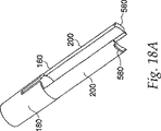
内側ハウジング25はその末端から延びる3つのトリガ突起100を有する。これらのトリガ突起100はラム125(図17)の環状くぼみ140に合致するような形状を有する。ラム125は圧縮バネ240により注射装置の末端の方へ押圧されるが、約2.5秒又はそれ以下で2ミリリットルまでの注射を生じさせることのできる他の付勢装置を使用することができる。このような付勢源は典型的にはゴムエラストマー及び圧縮されたガスカートリッジを含む。図18aに示すラッチ160は外側ハウジング45内で摺動でき、内側ハウジング25を取り巻く。ラッチ160はその末端でのバレル部分180と、その基端での一対の延長部200とを有する。ジェット式注射装置の始動の準備が整ったとき、図18bに示すバレル部分180上の隆起部225がトリガ突起100と接触し、これらをラム125の環状くぼみ140内に維持し、ラム125が圧縮バネ240の力の下で始動するのを阻止する。
【0036】
図19、32に示す針ホルダ260は右手ネジ280により内側ハウジング25上に装着され、内側ハウジング25内にカートリッジ組立体300を保持する。図20aに明示するように、カートリッジ組立体300はその基端での開口340及びその末端でのシール360を有するガラスアンプル320からなる。ガラスアンプル320は典型的には0.02ないし2ミリリットルの薬剤を保持する。ガラスの代わりに、アンプル320は金属又は当業界で既知の他の適当な材料で構成することができる。ゴムストッパ380はガラスアンプル320内で摺動でき、ガラスアンプル320の基端で開口340をシールし、そのため、薬剤400はガラスアンプル320内に留まる。末端上のシール360はその端部に穴を有するアルミニウムキャップ440の如き普通の技術によりアンプル320の端部に形成されたゴムシール420からなる。ラム125はガラスアンプル320の基端の開口340内へ延び、ゴムストッパ380と当接する。装置の状態の可視表示を提供するため、外側ハウジング45の少なくとも一部は透明又は半透明な材料で構成され、そのため、使用者はカートリッジ組立体300を見ることができる。
【0037】
図21に示す針組立体460は針ハブ520内の長手方向の凹所500内ににかわ付けされた注射針480を有する。長手方向の凹所500及び注射針480上の溝又は他の表面処理が注射針480と針ハブ520との間の結合を向上させる。代わりに、モールド成形の如き他の既知の固定方法を使用して、針ハブ520に注射針480を固定することができる。
【0038】
適当な注射時間を許容するため、注射針480は27ゲージのものとするが、異なる応用に対しては他のゲージが適することがある。針ハブ520の末端を越えて延び、注射に使用される針480の長さは、好ましくは1ないし5mmである。図21bに示すように、注射針480は好ましくは30゜の角度のポイントを有する。この角度は傾斜部481の長さを減少させ、それ故、内腔483の有効長さを増大させる。内腔483の有効長さの増大は不完全注射の百分率を減少させる。
【0039】
針組立体460は針ホルダ260に装着され、ほぼ1/4回転の針ホルダ260の右回り回転が針組立体を内側ハウジング25内へ更にねじ込み、注射針480の基端をゴムシール420を通して押し込み、薬剤経路を形成する。
【0040】
図22aに示す針ガード540は注射装置の末端に位置し、注射針480を隠す。針ガード540は図23a、23bに示す針ガードキャップ560と一緒にスナップ運動する。針ガードキャップ560はラッチ160の延長部200上で摺動し、針ガード540が注射針480を露出させるように注射装置の末端上で長手方向に摺動できるようにする。延長部200の端部での脚部580は、針ガードキャップ560従って針ガード540が装置の端部から完全に滑出するのを阻止する。
【0041】
針ガード540内のくぼみ600及び針ホルダ260上の対応するボス620は針ガード540のいかなる回転をも針ホルダ260の回転に変換する。図23bに示す針ガードキャップ560の内表面上の当接部655は、針ホルダ260の左回り回転を阻止するように、ラッチ160の脚部580に関して位置する。これは、使用者が装置を螺外ししててそこからカートリッジ組立体300を取り外すのを阻止する。
【0042】
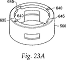
針ガードキャップはその中に一対のカットアウト部645を備えた内側フランジ635を有する。カットアウト部645は内側ハウジング25の対をなすボス625に対応する。フランジ635は、カットアウト部645が対をなすボス625と整合するように回転しない限りは、装置の基端の方への針ガードキャップ560及び針ガード540の運動を阻止する。これは、注射装置の偶発的な始動を阻止するための安全特徴として作用する。代わりに、着脱自在な安全ストリップの如き他の既知の機構を使用して、注射装置の偶発的な始動を阻止することができる。
【0043】
帰還バネ660(図示せず)は針ホルダ260上に位置し、針ガード540を注射装置の末端の方へ押圧し、注射針480を隠れた状態に保つ。図23に示す一対のストッパ640は針ガードキャップ560から延び、針ガード540及び針ホルダ260が帰還バネ660の力の下に右回りに回転できないように、内側ハウジング25上のボス625に関して位置決めされる。
【0044】
針ガード540を注射装置の基端の方へ押圧すると、針ガードキャップ560がラッチ160を装置の基端の方へ長手方向に押圧し、ラッチ160のバレル部分180上の隆起部225を内側ハウジング25上のトリガ突起100から離れるように移動させる。これは、トリガ突起100がラム125の環状のくぼみ140から出るように撓むのを許容し、圧縮バネ240の力の下でラム125を始動させる。ラム125が始動したとき、ラムはゴムストッパ380をガラスアンプル320内で装置の末端の方へ摺動させ、(上述のように、始動前に針ホルダ260を1/4回転右回りに回転させることにより生じる)薬剤経路を通して薬剤を流れさせ、注射針480から薬剤を排出させる。
【0045】
図22bに示すように、針ガード540はその中に位置する凹所680を有する。図24に示す係止リング700は凹所680内に位置し、装置が始動してしまった後に注射針480の再露出を阻止する。係止リング700は第1の端部での多数の広がった脚部720と、針ホルダ260から突出する延長部760に合致する第2の端部でのアンダーカット部740とを有する。係止リング700は針ホルダ260の延長部760上の同様に形状づけられた傾斜部分765と係合するようになった傾斜部分745を第2の端部に有する。傾斜部分745、765は針ホルダ260の延長部760と係止リング700のアンダーカット部740との間の合致を容易にする。針ガード540を装置の基端の方へ押したとき、延長部760がアンダーカット部740と係合し、その上で係止される。針ガード540がその元の位置へ戻ると、係止リング700は針ガード540の凹所680から引き出され、広がった脚部720が半径方向外方へ拡張する。針ガード540を再度押圧しようとすると、広がった脚部720が針ガード540上の肩部780を捕捉して、針ガード540の更なる運動を制限し、注射針480の再露出を阻止する。
【0046】
図32を参照すると、針ホルダ260の好ましい実施の形態が示されている。針ホルダ260は、その末端での傾斜部分765と、その基端での円筒状の壁部分761とを備えた延長部760を有する。内壁762は針ホルダの末端と基端との間に設けられ、針組立体520を受け入れるための円形開口763を有する。内壁762は好ましくは円筒状の壁部分761に対して実質上垂直に配置される。針ハブ520は針ホルダ260の円筒状の壁部分761内に嵌合し、針組立体520は、針480が延長部760を越えて外へ延びるように、開口763を通って延びる。延長部760は内壁762から外方へ末端方向に延びる。ボス620は内壁762とほぼ同じ平面内で内壁762から外方へ横断方向に延びる。ボス620はまた、ボス620が針ホルダ260の最外側部分となるように、円筒状の壁部分761から外方へ横断方向に延びる。
【0047】
図32に示す針ホルダ260の1つの実施の形態においては、針ホルダ260は約0.62インチ(約15.75mm)の長さを有する。傾斜部分765は好ましくは約20゜の角度Gである。寸法Bが約0.539インチ(約13.69mm)となるように、傾斜部分はほぼ0.08インチ(約2.03mm)の長さを有する。延長部760は、寸法Cがほぼ0.48インチ(約12.19mm)となるように、係止リング700のアンダーカット部740に係合するようになった肩部764を有する。円筒状の壁部分761は好ましくは0.32インチ(約8.13mm)の長さDを有し、ほぼ0.025インチ(約0.64mm)の半径を有する内半径湾曲Kを介して内壁762と関連する。円筒状の壁部分762はほぼ0.005インチ(約0.18mm)の半径を有する内半径湾曲部分Jを介してボス620と関連する。円筒状の壁部分761は好ましくは、外径開口Hが内径開口Iよりも大きくなるように、外方へ広がる。1つの実施の形態においては、外径開口Hはほぼ0.39インチ(約9.91mm)であり、内径開口Iはほぼ0.381インチ(約9.68mm)である。この実施の形態においては、内壁762の円形開口763はほぼ0.17インチ(約4.32mm)の直径Eを有し、延長部760間の距離Fはほぼ0.3インチ(約7.62mm)である。
【0048】
ここで、図33を参照すると、係止リング700の基端はアンダーカット部740及び傾斜部分745を含むものとして示されている。係止リング700の1つの実施の形態においては、傾斜部分745は好ましくはほぼ60゜の角度Mであり、ほぼ0.035インチ(約0.89mm)の長さNを有する。アンダーカット部740は係止リング700の基端に関してほぼ0.05インチ(約1.27mm)の距離Oだけ内側に形成される。係止リング700はほぼ0.05インチ(約1.27mm)の厚さLを有し、アンダーカット部740はほぼ0.02インチ(約0.51mm)の距離Pだけ横断方向に延びる。傾斜745は針ホルダ260の傾斜部分765と係合するように形状づけられ、寸法決めされる。
【0049】
係止リング700の基端及び針ホルダ260のための種々の寸法を図32、33で提供したが、これらは本質的に単なる例示である。他の寸法も有用で機能的であり、本発明はそのような範囲に限定されないことを理解すべきである。
【0050】
装置はまた、針ガード540上で摺動し、その使用前の装置を覆う着脱可能な安全キャップ800を特徴とする。安全キャップ800はこれに接続された針キャップ820(図26)を有し、針キャップ820は針組立体460のまわりに無菌バリヤを形成する。図25に示すように、安全キャップ800はその内表面840のまわりに等間隔で位置する4つの長手方向のくぼみ860を有する。これらの長手方向のくぼみ860は針ガード540上の対応する位置に位置する2又はそれ以上のボス880を受け入れるように寸法決めされる。これら2つの特徴のため、安全キャップ800の右回り回転が針ガード540及び針ホルダ260の対応する回転を生じさせる。従って、使用者は、薬剤経路を形成し、注射のために装置を準備するために、安全キャップを装置から取り外す前に、安全キャップ800を右回りに1/4回転旋回させることができる。
【0051】
好ましい実施の形態の装置は、最初に安全キャップ800を1/4回転だけ右回りに旋回させ、薬剤経路を形成するように注射針480の基端をアンプル320内に挿入することにより、作動される。また、安全キャップ800を回転させると、安全キャップ800のカットアウエー645が内側ハウジング25のボス625と整合し、針ガード540が押圧されるのを許容する。次に、安全キャップ800、続いて針キャップ820を装置から取り外す。
【0052】
図28−31を参照すると、注射工程の一連の位置を示す装置の作動が示されている。図28を参照すると、ラッチ止めされた注射の準備位置ではあるが、使用者の皮膚に対して押し付けられる前の装置が示されている。針ガード540は完全に伸長した状態で示され、針480は針ガード540内に引き戻されている。図29においては、装置は使用者の皮膚に対して押し付けられ、針ガード540は部分的に押し戻されている。ホルダ260の傾斜部分765及び係止リング700の傾斜745は接触する。互いに摺動する2つの傾斜部分の作用が帰還バネ(図示しないが、位置660として参照される位置)よりも大きな力を発生させる。使用者が皮膚に対して針ガード540を押し続けると、ホルダ260の延長部760が係止リング700のアンダーカット部740内へ押し込まれる。アンダー740内へ延長部760を押し込むのに必要な力は装置を始動するために打ち勝たねばならないしきい値である。しきい力に打ち勝つように延長部760がアンダーカット部740内へ押し込まれた後、ホルダ260は係止リング内へ前方に迅速に摺動し、注射装置を始動させる。装置の末端が注射箇所に対して押し付けられると、注射針480は1ないし5mmの深さまで皮膚に侵入する。針ガード540の運動はラム125を始動させ、その結果、0.02ないし2.0ミリリットルの薬剤400がアンプル320から押し出され、約2.75秒以下で薬剤経路を通過する。
【0053】
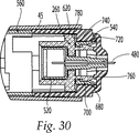
図30に示すように、針480は、使用者の皮膚へ侵入し、注射装置が始動されてしまうように、十分に伸長する。延長部760はアンダーカット部740内へ押し込まれる。延長部760とアンダーカット部740との間の係合は、ホルダ260及び係止リング700が分離するのを阻止する。
【0054】
図31を参照すると、注射箇所から除去された後の針ガード540が示されている。装置が注射箇所から除去された後、針ガード540は帰還バネ660の力の下にその元の位置へ戻り、注射針480を隠す。係止リング700の脚部720は針ガード540の凹所680から引き出され、伸長するか又は外方へ広がる。この位置において、使用者が針480の再使用を試みた場合、脚部720は針ガード540の肩部780と係合し、再使用を阻止する。このようにして、係止リング700は注射針480の再露出を阻止するために針ガード540を適所に係止する。代わりに、押しボタンを装置の基端に位置させて、アイドル位置で係止させることができる。針ガード540の運動が押しボタンを係止解除でき、使用者がそれを押し、続いて装置を始動させるのを可能にする。
【0055】
図20bは好ましい実施の形態のカートリッジ組立体302の別の実施の形態を示す。カートリッジ組立体302はガラスアンプル322と、その末端でシールされた針組立体462とを有する。穿孔可能なシール422は注射針482の基端の近傍に位置し、薬剤402と注射針482との間にバリヤを形成する。ゴムストッパ382はガラスアンプル322内で摺動でき、基端の開口342をシールし、そのため、薬剤402はガラスアンプル322の内部に留まる。注射装置の始動時に、ラム125はゴムストッパ382を注射装置の末端の方へ押圧する。薬剤402が非圧縮性の流体なので、穿孔可能なシール422は注射針482の末端上へ押され、バリヤを破壊し、薬剤経路を形成する。このカートリッジ組立体302では、薬剤経路を形成するために装置を旋回させる必要はなく、内側ハウジング25上及び針ホルダ260上のネジ部は、にかわ付け又は溶接の如き既知の恒久的な固定技術と交換することができる。
【0056】
本発明に係る針アシスト型のジェット式注射装置の重要な利点は、所望の割合での薬剤の低圧送給を可能にすることである。これに関し、固定の又は引き戻し可能な針を使用しての注射の投与は普通のジェット式注射装置装置よりも小さなエネルギ及び力で済む。図27はジェット式注射装置のための圧力/時間曲線を示す。点cでのピーク圧力は皮膚を穿孔するのに必要な圧力であり、点d及びそれ以降は薬剤のジェットストリームが送給される圧力である。次の表に示すように、針アシスト型のジェット式注射装置は従来のジェット式注射装置ほど大きなピーク圧力を達成する必要がない。その理由は、皮膚の外側層が針により穿孔されるからである。
【0057】
【表1】

所望の領域へ薬剤を送給し、更に短い注射時間を達成するために低いピーク圧力を使用することができる。また、針及びジェット注射が所望の領域に達した後にジェットストリームを送給するために低い定常圧力を使用することができる。
【0059】
減少した作動圧力は、ガラスアンプルが破壊する機会を減少させる。次の表は種々の圧力での実際の破壊率のガウス分布に基づく、異なる圧力でのガラスカートリッジに対する破壊の統計学上の予測を示す。
【0060】
【表2】
圧力の比較的小さな増大(≒100p.s.i)は2桁の大きさだけ破壊率を増大させる。従って、本発明の針アシスト型のジェット式注射装置の減少した作動圧力はアンプル破壊の危険性を大幅に減少させる。
【0062】
本発明に係る針アシスト型の注射装置は一層低いエネルギ発生源を使用して作動させることができ、注射の質を更に維持できることを、実験で確認した。特に、55ポンド力発生手段を有する従来の針無しジェット式注射装置のような1mmの深さまで皮膚を穿孔する針及び20ポンド力発生手段を有する針アシスト型のジェット式注射装置により、好結果をもたらす注射の一層高い百分率を達成できることを、実験は示した。1−3mm穿孔する針及び20ポンド及び40ポンドの力を提供する力発生手段により、同様の結果が達成された。
【0063】
次の表に示す本発明に係る針アシスト型のジェット式注射装置の別の利点は、注射器及び自動注射装置に比べて注射時間が短いことである。
【0064】
【表3】
(ただし、単位は、バネ力=ポンドf、流体室直径=インチ、平均圧力=psi、注射容積=ミリリットル、注射時間=秒である)
先に述べたように、自動注射装置及び注射器は数秒又はそれ以上の注射時間を有する。この注射時間中、注射の質は任意の数の因子のために低下することがある。例えば、患者が注射の完了前に注射器又は自動注射装置を動かすことがある。このような運動は注射に伴う痛みのために偶発的又は意図的に発生することがある。これに対し、他のジェット式注射装置のような針アシスト型の注射装置は1秒以下の注射時間を有する。短い注射時間は注射の質を低下させる可能性を減少させる。
【0066】
ここに開示された本発明の図示の実施の形態は上述の目的を満たすこと明らかであるが、当業者により種々の修正及び他の実施の形態を工夫することができることを認識すべきである。それ故、特許請求の範囲は本発明の精神及び要旨内に入るそのようなすべての修正及び実施の形態を保護することを意図するものと理解されたい。
【図面の簡単な説明】
【図1】本発明に係る針アシスト型のジェット式注射装置の横断面図である。
【図2】図1のジェット式注射装置上の針の横断面図である。
【図3】図2の針の斜視図である。
【図4】針が引き戻し位置にある状態での図1のジェット式注射装置の拡大横断面図である。
【図5】針が伸長位置にある状態での図1のジェット式注射装置の拡大横断面図である。
【図6】本発明に係る針の第2の実施の形態を示す斜視図である。
【図7】図6の針が引き戻し位置にある状態での本発明に係るジェット式注射装置の部分横断面図である。
【図8】図6の針が伸長位置にある状態での本発明に係るジェット式注射装置の部分横断面図である。
【図9】引き戻し素子としての可撓性部材及び針が引き戻し位置にある状態での本発明の別の実施の形態を示す横断面図である。
【図10】針が伸長位置にある状態での図9の実施の形態を示す横断面図である。
【図11】固定の針を有する2部品ノズル組立体の横断面図である。
【図12】固定の針を有する2部品ノズル組立体の別の実施の形態を示す横断面図である。
【図13】固定の針を有する2部品ノズル組立体の別の実施の形態を示す横断面図である。
【図14】図14aは本発明の好ましい実施の形態に係る針アシストのジェット式注射装置の横断面図であり、図14bは図14aの面に垂直な面に沿った図14aの針アシスト型のジェット式注射装置の横断面図である。
【図15】図14a、14bの針アシスト型のジェット式注射装置の外側ハウジングの斜視図である。
【図16】図14a、14bの注射装置の内側ハウジングの斜視図である。
【図17】図14a、14bの注射装置のラムの立面図である。
【図18】図18aは図14a、14bのラッチ組立体の斜視図であり、図18bは図18aのA−A線における図14a、14bのラッチ組立体の横断面図である。
【図19】図14a、14bの針ホルダの斜視図である。
【図20】図20aは図14a、14bのカートリッジ組立体の横断面図であり、図20bは図14a、14bのカートリッジ組立体の別の実施の形態を示す横断面図である。
【図21】図21aは図14a、14bの針組立体の横断面図であり、図21bは図14a、14bの注射針の横断面図である。
【図22】図22aは図14a、14bの針ガードの斜視図であり、図22bは図22aの針ガードの横断面図である。
【図23】図23aは図14a,14bの針ガードの第1の斜視図であり、図23bは図14a、14bの針ガードキャップの第2の斜視図である。
【図24】図14a、14bの係止リングの斜視図である。
【図25】図14a、14bの安全キャップの斜視図である。
【図26】図14a、14bの針キャップの横断面図である。
【図27】ジェット式注射装置のための圧力/時間曲線を示す概略図である。
【図28】安全キャップを取り外した状態での本発明に係るジェット式注射装置の別の実施の形態を示す部分横断面図であり、針ガードが完全に伸長した状態での使用前及びその準備における引き戻し位置での針を備えた注射装置の注射端部を示す図である。
【図29】針が部分的に引き戻された位置にあり、針ガードが使用前に注射表面に対してあたかも部分的に押し付けられるような中間位置にあるが注射装置を作動させるのに十分なほどには押し付けられていない状態での図28のジェット式注射装置の横断面図である。
【図30】針が伸長位置にあり、注射装置が使用者内へ注射始動されてしまった状態での図28のジェット式注射装置の横断面図である。
【図31】針が使用後に引き戻し位置にあり、不作動位置へ係止された状態での図28のジェット式注射装置の横断面図である。
【図32】図28の針ホルダの横断面図である。
【図33】図28の係止リング上の突起の横断面図である。[0001]
FIELD OF THE INVENTION
The present invention relates to a locking mechanism for use with a device for drug delivery, and in particular, a short needle to reduce the possibility of unintentional contact with the needle and prevent intentional reuse of the needle. WithJet injection deviceIt is related with the locking mechanism used together.
[0002]
BACKGROUND OF THE INVENTION
No wide range of needlesInjection deviceAre known in the art. like thisInjection deviceExamples include those disclosed in US Pat. Nos. 5,599,302, 5,062,830, and 4,790,824. In general, these and similarInjection deviceAdministers the drug as a thin, high-speed jet delivered under sufficient pressure to allow the jet to pass through the skin.
[0003]
The skin is a tissue composed of several layers,Injection deviceIs applied to the outer surface of the outermost layer, so the delivery pressure must be high enough to penetrate all layers of the skin. The skin layers include the epidermis, the outermost layer of the skin, the dermis and the subcutaneous region. The required delivery pressure is typically approximately 4000 p.p. (measured as fluid stream force divided by fluid stream cross-sectional area). s. i. It is.
[0004]
MostInjection deviceWhile this pressure can be easily achieved in some situations, it is desirable to deliver the drug to the subcutaneous region under reduced pressure. For example, a drug that requires a specific molecular structure, such as a linear protein shape, may become ineffective due to shear forces generated by the delivery of the drug at high pressures that alter the drug's structure. The use of lower pressures facilitates the delivery of large volumes of fluid, as it is more difficult to deliver large volumes of fluid at high pressures than small volumes. Furthermore, the lower pressure isinjectionThe device can be manufactured at a lower cost. Lower pressure also reduces adverse stress on the device and increases the usable device life. In addition, lower pressures can cause jet injection,Jet injection deviceMaking it compatible with the drug stored and delivered in glass ampoules that are typically unable to withstand the pressures typically achieved.
[0005]
Without needleJet injection deviceOne of the advantages associated with is the absence of a hypodermic needle. Given the fear of the needles everyone has, needleless offers a psychological benefit. Even devices that use ordinary hypodermic needles were designed to take advantage of this psychological benefit. For example, self such as those disclosed in U.S. Pat. Nos. 4,553,962 and 4,378,915.Injection deviceOr automaticInjection deviceHas a retractable needle that is hidden until activated. In operation, the needle extends from the bottom of the device and delivers the drug through the user's skin. Since none of these devices involve the delivery of medication using jet injection, the location of medication delivery is limited by the length of the needle. For example, if it is desired to deliver into the subcutaneous region, the needle must be long enough to reach the subcutaneous region. In addition, automaticInjection deviceSince it operates like a syringe, the injection time is a few seconds or longer. In contrast,Jet injection deviceIs typically a fraction of a second.
[0006]
U.S. Pat. No. 5,304,128 discloses a jet injection syringe that uses a short needle to assist in the injection. The syringe uses a gas powered driven plunger to drive the drug out of the needle through the syringe. The needle is pulled back until the syringe is driven and then extended to pierce the human skin to be injected. However, after the syringe is used, the needle remains in the extended state. Extended needles can cause potential biohazards, such as accidental injections and disease spreads, and safety considerations. Gas powered plungers are complex and expensive to manufacture.
[0007]
PCT Publication WO 99/03521 discloses an undefined concept of “jet” injection. However, this specification does not teach the details of the drive mechanism necessary to implement the concept.
[0008]
PCT publication WO 99/22790 specification isInjection deviceNeedle-assist type with retractable shield that hides the needle both before and after useInjection deviceTeaches. DisclosedInjection deviceHas a drive mechanism that operates at a pressure generated by a chemical reaction. Because of this chemically operated drive mechanism,Injection deviceThe injection time is at least 3 seconds, more likely to be 5 seconds or more. This relatively long injection time can be uncomfortable for the patient receiving the injection. Also, the needle may move during long injections, increasing patient discomfort.
[0009]
Even in the case of minimally invasive medical procedures, it is advantageous to keep the time for the procedure to a minimum. Therefore, it can operate at a relatively low pressure, and needle assist that can deliver medicine quicklyType jet injection deviceThere is a request. Also, such needles with retractable or concealed needles to prevent medical hazards associated with exposed needlesInjection deviceThere is also a request. It also has a retractable or concealable needle that can only be used once so that after use, it is blocked from subsequent use until it is removed or replacedInjection deviceThere is also a request.
[0010]
SUMMARY OF THE INVENTION
The present invention is a needle assistType jet injection deviceIt is related with the locking mechanism used together. Needle assistType jet injection deviceHas a needle assembly with a needle and a needle guard associated with the needle assembly. The needle guard is placed against the surface to be injected,Injection deviceThis is to protect the needle before and after injection. The needle guard is a first one in which the needle is pulled back inside the needle guard.Needle retractionExtends outside the needle guard for position and injection into the surfaceneedleAn extended position and a second position where the needle is pulled back into the needle guard after injectionNeedle retractionYou can move between positions.
[0011]
The locking mechanism has a holder member and a locking member. The holder member is shaped and dimensioned to hold the needle assembly and has at least one first engaging portion. The locking member is operatively associated with the needle guard and the engagement portion. The locking memberneedleExtended position and secondNeedle retractionAt least one second engagement portion adapted to engage at least one first engagement portion of the holder member in position. The locking member is the firstNeedle retractionAssociated with the needle guard in position,needleExtended position and secondNeedle retractionIn relation to the holder member in position,needleA second so as to prevent further movement of the needle guard into the extended position and prevent reuse of the needleNeedle retractionIt is locked with the needle guard at the position.
[0012]
The locking member can have a substantially annular portion and at least one outwardly biased leg portion extending from the end of the annular portion. In this embodiment, the needle guard has the first locking member.Needle retractionAt least one for receiving at least one leg when associated with the needle guard in positionRecessHave The leg maintains its position relative to the needle guard due to its outwardly biased force and at least the needle guard upon application of a force sufficient to overcome the outwardly biased force of the leg. OneRecessIt has elasticity so that it can be removed.
[0013]
The second engaging portion of the locking member can have an undercut portion formed at the proximal end of the annular portion of the locking member. The undercut portion is preferably sized and shaped to receive a matching first engagement portion of the holder member. The proximal end of the annular portion can also have a beveled portion on the inner surface extending inwardly from that end. The angled portion of the locking member is angled with respect to the outer circumferential surface of the annular portion to engage the first engagement portion of the holder member before the holder member engages the undercut portion. .
[0014]
The outwardly biased leg of the locking member is preferably the needle guardRecessIt jumps outward after coming off. These legs are then secondNeedle retractionIn position, the needle guard is prevented from being reused by abutting against a shoulder formed on the inner surface of the needle guard and substantially preventing movement of the needle guard in the proximal direction.
[0015]
The holder member may have a substantially cylindrical portion at its proximal end, at least one first engagement portion at its distal end, and an inner wall located substantially therebetween. The cylindrical portion and inner wall are shaped and dimensioned to match the needle assembly.
[0016]
The inner wall of the holder member can have a circular opening extending between its proximal and distal sides to receive a portion of the needle assembly therethrough. The first engaging portion of the holder member is at least one arm extending distally from the inner wall. The arm preferably has an extension portion dimensioned and dimensioned to seat within the second engagement portion of the locking member. The extension portion of the arm can also have a beveled portion adapted to be associated with the locking member. The inclined portions of the holder member preferably allow both inclined portions to allow the other inclined portion to slide thereon so that the first engaging portion engages the second engaging portion in the extended position. In order to allow this, it can have a complementary shape with respect to the inclined portion of the locking member.
[0017]
[Description of Preferred Embodiment]
For convenience, the same or equivalent elements of the present invention in the embodiments shown in the figures are identified by the same reference numerals. Furthermore, in the following description, any reference to orientation or direction is intended primarily for convenience of description and is not intended to be in any way that limits the spirit of the invention thereto.
[0018]
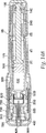
As shown in FIG.Jet injection device10 has a
[0019]
The
[0020]
The
[0021]
According to the first embodiment of the present invention, the
[0022]
[0023]
The
[0024]
The structure of the
[0025]
The outer periphery of the
[0026]
As shown in FIGS.
[0027]
To provide a seal between the
[0028]
FIG. 5 shows the
[0029]
FIGS. 7 and 8 show the
[0030]
9 and 10 use a
[0031]
Another embodiment of the present invention comprises a fixed needle, i.e. a non-retractable needle that extends permanently beyond the nozzle assembly.Injection deviceAbout. Both one-part and two-part nozzle assemblies with fixed needles can be used and are contemplated by the present invention.
[0032]
11 and 12 show an embodiment of the present invention having a two-part nozzle assembly with a fixed
[0033]
Another embodiment of a multi-part nozzle assembly with a fixed
[0034]
Figures 14a and 14b show a preferred embodiment of the present invention with a shield retractable about the needle. The
[0035]
[0036]
A
[0037]
The
[0038]
The
[0039]
The
[0040]
The
[0041]
The
[0042]
The needle guard cap has an
[0043]
A return spring 660 (not shown) is positioned on the
[0044]
Needle guard 540Injection device, The
[0045]
As shown in FIG. 22b, the
[0046]
Referring to FIG. 32, a preferred embodiment of the
[0047]
In one embodiment of the
[0048]
Referring now to FIG. 33, the proximal end of the
[0049]
Various dimensions for the proximal end of the
[0050]
The device also features a
[0051]
The device of the preferred embodiment is activated by first pivoting
[0052]
Referring to FIGS. 28-31, the operation of the device showing the sequence of positions for the injection process is shown. Referring to FIG. 28, the device is shown ready for latched injection but before being pressed against the user's skin.
[0053]
As shown in FIG. 30, the
[0054]
Referring to FIG. 31, the
[0055]
FIG. 20b shows another embodiment of the
[0056]
Needle assist according to the present inventionType jet injection deviceAn important advantage is that it allows low pressure delivery of the drug at the desired rate. In this regard, administration of injection using a fixed or retractable needle is common.Jet injection deviceLess energy and power than the device. FIG.
[0057]
[Table 1]
Low peak pressures can be used to deliver the drug to the desired area and achieve shorter injection times. Also, a low steady pressure can be used to deliver the jet stream after the needle and jet injection reach the desired area.
[0059]
The reduced operating pressure reduces the chance that the glass ampoule will break. The following table shows statistical predictions of failure for glass cartridges at different pressures based on a Gaussian distribution of actual failure rates at different pressures.
[0060]
[Table 2]
A relatively small increase in pressure (≈100 p.s.i) increases the failure rate by two orders of magnitude. Therefore, the needle assist of the present inventionType jet injection deviceThe reduced operating pressure greatly reduces the risk of ampoule breakage.
[0062]
Needle assist according to the present inventionMold injection deviceExperiments have confirmed that can be operated using a lower energy source and that the quality of the injection can be further maintained. In particular, no conventional needle with 55 pound force generating meansJet injection deviceNeedle assist with a needle that pierces the skin to a depth of 1 mm, such asType jet injection deviceExperiments have shown that a higher percentage of injections can be achieved with good results. Similar results were achieved with needles that drilled 1-3 mm and force generating means providing 20 and 40 pounds of force.
[0063]
Needle assist according to the present invention shown in the following tableType jet injection deviceAnother advantage of the syringe and automaticInjection deviceCompared to the short injection time.
[0064]
[Table 3]
(However, the unit is spring force = pound f, fluid chamber diameter = inch, average pressure = psi, injection volume = milliliter, injection time = second)
As mentioned earlier, automaticInjection deviceAnd the syringe has an injection time of several seconds or more. During this injection time, the quality of the injection may be reduced due to any number of factors. For example, if the patient has a syringe or automaticInjection deviceMay be moved. Such movement may occur accidentally or intentionally due to the pain associated with injection. In contrast, otherJet injection deviceNeedle assist likeMold injection deviceHas an injection time of 1 second or less. Short injection times reduce the possibility of reducing the quality of the injection.
[0066]
While the illustrated embodiments of the present invention disclosed herein are apparently satisfactory for the purposes described above, it should be recognized that various modifications and other embodiments can be devised by those skilled in the art. Therefore, it is to be understood that the claims are intended to protect all such modifications and embodiments that fall within the spirit and spirit of the invention.
[Brief description of the drawings]
FIG. 1 shows a needle assist type according to the present invention.Jet injection deviceFIG.
2 is a diagram of FIG.Jet injection deviceFIG. 6 is a cross-sectional view of the upper needle.
FIG. 3 is a perspective view of the needle of FIG.
4 is a view of FIG. 1 with the needle in the retracted position.Jet injection deviceFIG.
5 is a view of FIG. 1 with the needle in the extended position.Jet injection deviceFIG.
FIG. 6 is a perspective view showing a second embodiment of the needle according to the present invention.
7 relates to the present invention with the needle of FIG. 6 in the retracted position.Jet injection deviceFIG.
FIG. 8 relates to the present invention with the needle of FIG. 6 in the extended position.Jet injection deviceFIG.
FIG. 9 is a cross-sectional view showing another embodiment of the present invention in a state where a flexible member as a pull-back element and a needle are in a pull-back position.
10 is a cross-sectional view showing the embodiment of FIG. 9 with the needle in the extended position.
FIG. 11 is a cross-sectional view of a two-part nozzle assembly having a fixed needle.
FIG. 12 is a cross-sectional view of another embodiment of a two-part nozzle assembly having a fixed needle.
FIG. 13 is a cross-sectional view illustrating another embodiment of a two-part nozzle assembly having a fixed needle.
FIG. 14a is an illustration of needle assist according to a preferred embodiment of the present invention.Jet injection device14b is a cross-sectional view of the needle assist of FIG. 14a along a plane perpendicular to the plane of FIG. 14a.Type jet injection deviceFIG.
FIG. 15: Needle assist of FIGS. 14a, 14bType jet injection deviceFIG.
FIG. 16 is a view of FIGS. 14a and 14b.Injection deviceFIG.
FIG. 17 is a view of FIGS. 14a and 14b.Injection deviceFIG.
18a is a perspective view of the latch assembly of FIGS. 14a and 14b, and FIG. 18b is a cross-sectional view of the latch assembly of FIGS. 14a and 14b taken along line AA of FIG. 18a.
FIG. 19 is a perspective view of the needle holder of FIGS. 14a and 14b.
20a is a cross-sectional view of the cartridge assembly of FIGS. 14a, 14b, and FIG. 20b is a cross-sectional view of another embodiment of the cartridge assembly of FIGS. 14a, 14b.
21a is a cross-sectional view of the needle assembly of FIGS. 14a, 14b, and FIG. 21b is a cross-sectional view of the injection needle of FIGS. 14a, 14b.
22a is a perspective view of the needle guard of FIGS. 14a and 14b, and FIG. 22b is a cross-sectional view of the needle guard of FIG. 22a.
FIG. 23a is a first perspective view of the needle guard of FIGS. 14a and 14b, and FIG. 23b is a second perspective view of the needle guard cap of FIGS. 14a and 14b.
FIG. 24 is a perspective view of the locking ring of FIGS. 14a and 14b.
FIG. 25 is a perspective view of the safety cap of FIGS. 14a, 14b.
FIG. 26 is a cross-sectional view of the needle cap of FIGS. 14a, 14b.
FIG. 27Jet injection deviceFIG. 6 is a schematic diagram showing a pressure / time curve for
FIG. 28 relates to the present invention with the safety cap removed.Jet injection deviceFIG. 6 is a partial cross-sectional view showing another embodiment of the present invention with a needle in a retracted position before use and in preparation in which the needle guard is fully extended.Injection deviceIt is a figure which shows the injection | pouring end part.
FIG. 29 is in an intermediate position where the needle is in a partially retracted position and the needle guard is partially pressed against the injection surface prior to use.Injection deviceOf FIG. 28 in a state where it is not pressed sufficiently to actuate theJet injection deviceFIG.
FIG. 30 shows the needle in the extended position;Injection deviceOf FIG. 28 in a state where injection has been started into the user.Jet injection deviceFIG.
FIG. 31 is a view of FIG. 28 with the needle in the retracted position after use and locked in the inoperative position.Jet injection deviceFIG.
32 is a cross-sectional view of the needle holder of FIG. 28. FIG.
33 is a cross-sectional view of a protrusion on the locking ring of FIG. 28. FIG.
Claims (11)
上記針組立体を保持するように形状づけられ、寸法決めされ、少なくとも1つの第1の係合部分を有するホルダ部材と;
上記針伸長位置及び上記第2の針引込め位置において当該ホルダ部材の上記少なくとも1つの第1の係合部分と係合するようになった少なくとも1つの第2の係合部分を有する係止部材と;
を有し、上記係止部材が上記第1の針引込め位置で上記針ガードにより保持され、上記針伸長位置及び上記第2の針引込め位置で上記ホルダ部材により係止され、当該針伸長位置への当該針ガードの更なる運動を防止しかつ上記針の再使用を阻止するように、当該第2の針引込め位置において該針ガードと係止関係になることを特徴とする係止機構。A needle-assist- type jet injection device for use in a needle-assist- type jet injection device , wherein the needle-assist- type jet injection device has a needle assembly having a needle and a needle guard, and the needle guard A first needle retractor which is arranged against the surface to be injected and is shaped to protect the needle before and after injection of the injection device , the needle guard being pulled back inside the needle guard between a position, a needle extended position in which the needle extends outside the needle guard for injection into the surface, a second needle retracted position in which the needle is pulled back to the inside of the needle guard after injection In the locking mechanism that can move
A holder member shaped and dimensioned to hold the needle assembly and having at least one first engagement portion;
A locking member having at least one second engaging portion adapted to engage with the at least one first engaging portion of the holder member at the needle extending position and the second needle retracting position. When;
The locking member is held by the needle guard at the first needle retracted position, and is locked by the holder member at the needle extended position and the second needle retracted position, and the needle extended further movement of the needle guard to a position to prevent reuse of preventing vital the needle, locking, characterized by comprising a needle guard and locking relationship in the second needle retracted position mechanism.
実質上環状の部分と;
上記環状の部分の末端から延びる少なくとも1つの外方へ偏倚された脚部と;を有し、
上記針ガードは少なくとも1つの凹所を有し、上記係止部材が上記第1の針引込め位置で当該凹所に保持されているときに上記少なくとも1つの脚部も上記凹所に受け入れられるようになっており、
上記脚部のその外方への偏倚力のために上記係止部材が上記針ガードの上記凹所内に保持された状態を維持し、当該脚部は、同脚部の上記外方への偏倚力に打ち勝つのに十分な力が作用したときに、上記針ガードの少なくとも1つの凹所から外れるように、弾性的になっていることを特徴とする請求項1に記載の係止機構。The locking member is
A substantially annular portion;
And at least one outwardly biased leg extending from the end of the annular portion;
The needle guard has at least one recess, and the at least one leg is also received in the recess when the locking member is held in the recess in the first needle retracted position. And
Maintaining the state in which the locking member for biasing force is held within the recess of the needle guard to its outward of the legs, the legs are biased towards the outer of Doashi portion The locking mechanism according to claim 1, wherein the locking mechanism is elastic so as to disengage from the at least one recess of the needle guard when a force sufficient to overcome the force is applied.
その基端での実質上円筒状の部分と;
その末端での上記少なくとも1つの第1の係合部分と;
実質上これらの間に位置する内壁と;
を有し、上記円筒状の部分及び上記内壁が上記針組立体と合致するように形状づけられ、寸法決めされることを特徴とする請求項1乃至5のいずれか1項に記載の係止機構。The holder member is
A substantially cylindrical portion at its proximal end;
Said at least one first engaging portion at its distal end;
An inner wall located substantially between them;
6. A lock according to any one of the preceding claims, wherein the cylindrical portion and the inner wall are shaped and dimensioned to match the needle assembly. mechanism.
その基端での実質上円筒状の部分と;
その末端での上記少なくとも1つの第1の係合部分と;
実質上これらの間に位置する内壁と;
を有し、上記円筒状の部分及び上記内壁が上記針組立体と合致するように形状づけられ、
寸法決めされ、
上記第1の係合部分が上記内壁から末端方向に延びる少なくとも1つのアームであり、
上記アームが上記係止部材の上記第2の係合部分と係合するように形状づけられ、寸法決めされる延長部分を有し、当該アームの上記延長部分が上記係止部材の上記傾斜部分と摺動して係合する傾斜部分を有することを特徴とする請求項4乃至8のいずれか1項に記載の係止機構。The holder member is
A substantially cylindrical portion at its proximal end;
Said at least one first engaging portion at its distal end;
An inner wall located substantially between them;
And the cylindrical portion and the inner wall are shaped to match the needle assembly,
Dimensioned,
The first engagement portion is at least one arm extending distally from the inner wall;
Said arm is shaped to be engaged with the second engagement portion of the locking member has an extension which is dimensioned, the inclined portion of the extension portion of the arm is the locking member The locking mechanism according to claim 4, further comprising an inclined portion that slides and engages .
Applications Claiming Priority (3)
| Application Number | Priority Date | Filing Date | Title |
|---|---|---|---|
| US09/425,965 US6391003B1 (en) | 1999-10-25 | 1999-10-25 | Locking mechanism for a jet injector |
| US09/425,965 | 1999-10-25 | ||
| PCT/US2000/029000 WO2001032255A1 (en) | 1999-10-25 | 2000-10-20 | Locking mechanism for a jet injector |
Publications (3)
| Publication Number | Publication Date |
|---|---|
| JP2003512904A JP2003512904A (en) | 2003-04-08 |
| JP2003512904A5 JP2003512904A5 (en) | 2007-12-13 |
| JP4236843B2 true JP4236843B2 (en) | 2009-03-11 |
Family
ID=23688751
Family Applications (1)
| Application Number | Title | Priority Date | Filing Date |
|---|---|---|---|
| JP2001534458A Expired - Lifetime JP4236843B2 (en) | 1999-10-25 | 2000-10-20 | Locking mechanism for jet injection device |
Country Status (8)
| Country | Link |
|---|---|
| US (1) | US6391003B1 (en) |
| EP (1) | EP1225952B1 (en) |
| JP (1) | JP4236843B2 (en) |
| CN (1) | CN1382064A (en) |
| AT (1) | ATE458516T1 (en) |
| AU (1) | AU1573501A (en) |
| DE (1) | DE60043894D1 (en) |
| WO (1) | WO2001032255A1 (en) |
Families Citing this family (98)
| Publication number | Priority date | Publication date | Assignee | Title |
|---|---|---|---|---|
| GB9716065D0 (en) * | 1997-07-31 | 1997-10-01 | Owen Mumford Ltd | Improvements relating to injection devices |
| DE10066400B4 (en) * | 2000-03-01 | 2012-01-19 | Tecpharma Licensing Ag | Injector cap for an ampoule support comprises a push-on sleeve mounted using a push fit, a pre-tensioning unit, a cannula and a locking unit |
| DE10009814B4 (en) * | 2000-03-01 | 2008-03-06 | Tecpharma Licensing Ag | Disposable injector |
| WO2001070309A1 (en) * | 2000-03-23 | 2001-09-27 | Antares Pharma, Inc. | Single use disposable jet injector |
| US6547764B2 (en) * | 2000-05-31 | 2003-04-15 | Novo Nordisk A/S | Double pointed injection needle |
| DE60112440T2 (en) * | 2000-05-31 | 2006-04-20 | Novo Nordisk A/S | DISPOSABLE 2-POINT INJECTION NEEDLE |
| EP3138598B1 (en) | 2000-08-02 | 2019-10-23 | Becton, Dickinson and Company | Pen needle and safety shield system |
| US7235063B2 (en) * | 2001-08-21 | 2007-06-26 | D'antonio Consultants International, Inc. | Hypodermic injection system |
| US6796967B2 (en) * | 2001-10-22 | 2004-09-28 | Nps Pharmaceuticals, Inc. | Injection needle assembly |
| GB0125506D0 (en) * | 2001-10-24 | 2001-12-12 | Weston Medical Ltd | Needle free injection method and apparatus |
| KR100879498B1 (en) * | 2001-11-30 | 2009-01-20 | 노보 노르디스크 에이/에스 | A safety needle assembly |
| EP1476210B1 (en) | 2002-02-11 | 2008-09-24 | Antares Pharma, Inc. | Intradermal injector |
| US7252651B2 (en) * | 2003-01-07 | 2007-08-07 | Becton, Dickinson And Company | Disposable injection device |
| US8932264B2 (en) * | 2003-08-11 | 2015-01-13 | Becton, Dickinson And Company | Medication delivery pen assembly with needle locking safety shield |
| GB2414401B (en) | 2004-05-28 | 2009-06-17 | Cilag Ag Int | Injection device |
| GB2414406B (en) | 2004-05-28 | 2009-03-18 | Cilag Ag Int | Injection device |
| GB2414409B (en) * | 2004-05-28 | 2009-11-18 | Cilag Ag Int | Injection device |
| GB2414775B (en) * | 2004-05-28 | 2008-05-21 | Cilag Ag Int | Releasable coupling and injection device |
| GB2414399B (en) * | 2004-05-28 | 2008-12-31 | Cilag Ag Int | Injection device |
| GB2414404B (en) | 2004-05-28 | 2009-06-03 | Cilag Ag Int | Injection device |
| GB2414402B (en) * | 2004-05-28 | 2009-04-22 | Cilag Ag Int | Injection device |
| GB2414405B (en) * | 2004-05-28 | 2009-01-14 | Cilag Ag Int | Injection device |
| GB2414400B (en) | 2004-05-28 | 2009-01-14 | Cilag Ag Int | Injection device |
| GB2414403B (en) * | 2004-05-28 | 2009-01-07 | Cilag Ag Int | Injection device |
| US8048035B2 (en) | 2004-08-06 | 2011-11-01 | Meridian Medical Technologies, Inc. | Automatic injector with needle cover |
| US7449012B2 (en) * | 2004-08-06 | 2008-11-11 | Meridian Medical Technologies, Inc. | Automatic injector |
| JP5216328B2 (en) | 2005-01-24 | 2013-06-19 | アンタレス ファーマ インコーポレイテッド | Pre-filled needle assist syringe jet injector |
| GB2424836B (en) | 2005-04-06 | 2010-09-22 | Cilag Ag Int | Injection device (bayonet cap removal) |
| GB2425062B (en) * | 2005-04-06 | 2010-07-21 | Cilag Ag Int | Injection device |
| GB2424835B (en) * | 2005-04-06 | 2010-06-09 | Cilag Ag Int | Injection device (modified trigger) |
| GB2424838B (en) * | 2005-04-06 | 2011-02-23 | Cilag Ag Int | Injection device (adaptable drive) |
| GB2427826B (en) | 2005-04-06 | 2010-08-25 | Cilag Ag Int | Injection device comprising a locking mechanism associated with integrally formed biasing means |
| DE602005018480D1 (en) | 2005-08-30 | 2010-02-04 | Cilag Gmbh Int | Needle device for a prefilled syringe |
| US20110098656A1 (en) | 2005-09-27 | 2011-04-28 | Burnell Rosie L | Auto-injection device with needle protecting cap having outer and inner sleeves |
| EP1958654A1 (en) * | 2005-12-05 | 2008-08-20 | Zhongshan Botai Pharmaceutic Instruments Co., Ltd. | An automatic syringe |
| WO2007131025A1 (en) | 2006-05-03 | 2007-11-15 | Antares Pharma, Inc. | Injector with adjustable dosing |
| US8251947B2 (en) | 2006-05-03 | 2012-08-28 | Antares Pharma, Inc. | Two-stage reconstituting injector |
| GB2438591B (en) | 2006-06-01 | 2011-07-13 | Cilag Gmbh Int | Injection device |
| GB2438590B (en) | 2006-06-01 | 2011-02-09 | Cilag Gmbh Int | Injection device |
| GB2438593B (en) | 2006-06-01 | 2011-03-30 | Cilag Gmbh Int | Injection device (cap removal feature) |
| WO2008072715A1 (en) * | 2006-12-13 | 2008-06-19 | Suzuken Company Limited | Injection needle cartridge and injector |
| US7871397B2 (en) | 2006-12-26 | 2011-01-18 | Stat Medical Devices, Inc. | Pen needle tip |
| US7540858B2 (en) * | 2007-01-23 | 2009-06-02 | Becton, Dickinson And Company | Retracting safety pen needle |
| DE102007008369A1 (en) * | 2007-02-16 | 2008-08-21 | Lts Lohmann Therapie-Systeme Ag | Disposable injector with at least one central tie rod |
| US8128605B2 (en) * | 2007-12-24 | 2012-03-06 | Mentor Worldwide Llc | Syringe for use in medical applications |
| EP2268342B1 (en) | 2008-03-10 | 2015-09-16 | Antares Pharma, Inc. | Injector safety device |
| GB2461086B (en) | 2008-06-19 | 2012-12-05 | Cilag Gmbh Int | Injection device |
| GB2461089B (en) | 2008-06-19 | 2012-09-19 | Cilag Gmbh Int | Injection device |
| GB2461085B (en) | 2008-06-19 | 2012-08-29 | Cilag Gmbh Int | Injection device |
| GB2461087B (en) | 2008-06-19 | 2012-09-26 | Cilag Gmbh Int | Injection device |
| GB2461084B (en) | 2008-06-19 | 2012-09-26 | Cilag Gmbh Int | Fluid transfer assembly |
| ES2738539T3 (en) | 2008-08-05 | 2020-01-23 | Antares Pharma Inc | Multi dose injector |
| WO2010108116A1 (en) | 2009-03-20 | 2010-09-23 | Antares Pharma, Inc. | Hazardous agent injection system |
| US20110023281A1 (en) * | 2009-04-30 | 2011-02-03 | Stat Medical Devices, Inc. | Pen injection device cap with integral pen needle quick release and/or removal system |
| US9700681B2 (en) * | 2009-05-15 | 2017-07-11 | Stat Medical Devices, Inc. | Pen needle with quick release and/or removal system |
| US20110026930A1 (en) * | 2009-07-29 | 2011-02-03 | Zhi Cui | Methods and apparatus to upgrade communication services in subscriber distribution areas |
| US20110060292A1 (en) * | 2009-08-14 | 2011-03-10 | Stat Medical Devices, Inc. | Pen needle storage device with integral removal and/or installation system |
| JP5918752B2 (en) * | 2010-08-23 | 2016-05-18 | 南部化成株式会社 | Transdermal administration device and needle forming body used in the device |
| JP5631128B2 (en) * | 2010-09-07 | 2014-11-26 | 株式会社トクヤマデンタル | Knock-type discharge container |
| US10463803B2 (en) | 2010-11-12 | 2019-11-05 | Stat Medical Devices, Inc. | Pen needle with quick release and/or removal system |
| US8961470B2 (en) | 2011-02-17 | 2015-02-24 | Steven Schraga | Pen needle with safety shield system |
| US9884156B2 (en) * | 2011-04-28 | 2018-02-06 | Sanofi-Aventis Deutschland Gmbh | Lockout element for dispense interface |
| CN105536111A (en) * | 2011-04-28 | 2016-05-04 | 赛诺菲-安万特德国有限公司 | Dispense interface with lockout element |
| WO2012161685A1 (en) * | 2011-05-23 | 2012-11-29 | Boehringer Ingelheim International Gmbh | Nebulizer |
| DE102011107199A1 (en) * | 2011-07-13 | 2013-01-17 | Haselmeier Gmbh | Injection device and method for its production |
| US8496619B2 (en) | 2011-07-15 | 2013-07-30 | Antares Pharma, Inc. | Injection device with cammed ram assembly |
| US9220660B2 (en) | 2011-07-15 | 2015-12-29 | Antares Pharma, Inc. | Liquid-transfer adapter beveled spike |
| US9149580B2 (en) | 2011-07-19 | 2015-10-06 | Sanofi-Aventis Deutschland Gmbh | Cartridge holder for a drug delivery device |
| EP2572744A1 (en) * | 2011-09-23 | 2013-03-27 | Sanofi-Aventis Deutschland GmbH | Needle safety device |
| EP2578258A1 (en) * | 2011-10-06 | 2013-04-10 | Sanofi-Aventis Deutschland GmbH | Needle safety device |
| US9078978B2 (en) | 2011-12-28 | 2015-07-14 | Stat Medical Devices, Inc. | Needle assembly with safety system for a syringe or fluid sampling device and method of making and using the same |
| JP6165786B2 (en) | 2012-03-06 | 2017-07-19 | アンタレス・ファーマ・インコーポレーテッド | Filling syringe with release force feature |
| KR20150011346A (en) | 2012-04-06 | 2015-01-30 | 안타레스 팔마, 인코퍼레이티드 | Needle assisted jet injection administration of testosterone compositions |
| WO2013169800A1 (en) | 2012-05-07 | 2013-11-14 | Antares Pharma, Inc. | Injection device with cammed ram assembly |
| CA2900672C (en) | 2013-02-11 | 2018-03-27 | Antares Pharma, Inc. | Needle assisted jet injection device having reduced trigger force |
| JP6030803B2 (en) | 2013-03-11 | 2016-11-24 | アンタレス・ファーマ・インコーポレーテッド | Dose syringe with pinion system |
| WO2014165136A1 (en) | 2013-03-12 | 2014-10-09 | Antares Pharma, Inc. | Constant volume prefilled syringes and kits thereof |
| JP6211790B2 (en) | 2013-04-23 | 2017-10-11 | 大成化工株式会社 | Syringe |
| GB2515032A (en) | 2013-06-11 | 2014-12-17 | Cilag Gmbh Int | Guide for an injection device |
| GB2515038A (en) | 2013-06-11 | 2014-12-17 | Cilag Gmbh Int | Injection device |
| GB2517896B (en) | 2013-06-11 | 2015-07-08 | Cilag Gmbh Int | Injection device |
| GB2515039B (en) | 2013-06-11 | 2015-05-27 | Cilag Gmbh Int | Injection Device |
| CA2926439C (en) | 2013-10-07 | 2019-04-16 | Antares Pharma, Inc. | Hematocrit modulation through needle assisted jet injection of testosterone |
| EP3107547A4 (en) | 2014-02-19 | 2017-11-15 | Antares Pharma, Inc. | Needle assisted jet injection administration of testosterone compositions |
| US10118000B2 (en) | 2014-04-21 | 2018-11-06 | Stat Medical Devices, Inc. | Pen needle installation and removal safety cover and pen needle assembly utilizing the same |
| US10155091B2 (en) | 2014-07-11 | 2018-12-18 | Stat Medical Devices, Inc. | Pen needle tip and method of making and using the same |
| JP2017523858A (en) | 2014-08-10 | 2017-08-24 | アンタレス・ファーマ・インコーポレーテッド | Syringe buffer for use in an injection device |
| CA3009221A1 (en) | 2014-12-23 | 2016-06-30 | Automed Pty Ltd | Delivery apparatus, system and associated methods |
| US10251964B2 (en) | 2016-08-23 | 2019-04-09 | Drma Group International Llc | Self-disinfecting needleless device |
| US10195110B2 (en) | 2016-09-08 | 2019-02-05 | Drma Group International Llc | Capping device for disinfecting medical container |
| US10391294B2 (en) | 2016-09-12 | 2019-08-27 | Drma Group International Llc | Disinfecting cap |
| US10610676B2 (en) | 2016-09-26 | 2020-04-07 | Drma Group International Llc | Disinfecting luer connector |
| US10182968B2 (en) | 2017-03-06 | 2019-01-22 | Drma Group International Llc | Disinfecting capping device for sharp medical objects |
| US11541219B2 (en) | 2017-07-10 | 2023-01-03 | Drma Group International Llc | Capping device for disinfecting medical injection membranes |
| JP2021519669A (en) * | 2018-04-01 | 2021-08-12 | ノボ・ノルデイスク・エー/エス | Automatic injection device with memory elements |
| WO2019237082A1 (en) | 2018-06-08 | 2019-12-12 | Antares Pharma, Inc. | Auto-insert injector |
| KR20220062395A (en) * | 2019-09-17 | 2022-05-16 | 벡톤 디킨슨 홀딩즈 피티이 엘티디. | Manual safety device, injection device comprising same, and method for manufacturing said injection device |
| CN110882447A (en) * | 2019-11-11 | 2020-03-17 | 徐州深丰精密机械有限公司 | Medical syringe assembly |
Family Cites Families (37)
| Publication number | Priority date | Publication date | Assignee | Title |
|---|---|---|---|---|
| DE1957833A1 (en) | 1968-11-21 | 1970-07-02 | Maurice Steiner | Injection syringe, especially injection syringe handled by the patient himself |
| US3605744A (en) | 1969-04-22 | 1971-09-20 | Edward M Dwyer | Injection apparatus and method of injecting |
| US3797491A (en) | 1971-02-11 | 1974-03-19 | Ampoules Inc | Method of performing an intramuscular injection |
| BE795162A (en) | 1972-02-10 | 1973-08-08 | Philips Nv | INJEKTIE-INRICHTING |
| FR2237643B1 (en) | 1973-07-17 | 1978-03-17 | Steiner Maurice | |
| SE7502318L (en) | 1975-03-03 | 1976-09-06 | Af Ekenstam Thuresson Bo | PACKAGING FOR LIQUID FOR SEMI-SOLID MATERIAL, SUITABLE FOR SMALLER QUANTITIES |
| US4127118B1 (en) | 1977-03-16 | 1995-12-19 | Alvaro Latorre | Method of effecting and enhancing an erection |
| US4227528A (en) | 1978-12-26 | 1980-10-14 | Wardlaw Stephen C | Automatic disposable hypodermic syringe |
| US4258713A (en) | 1979-07-23 | 1981-03-31 | Wardlaw Stephen C | Automatic disposable hypodermic syringe |
| US4378015A (en) | 1981-12-21 | 1983-03-29 | Wardlaw Stephen C | Automatic injecting syringe |
| FR2539302B1 (en) | 1983-01-17 | 1986-03-14 | Brunet Jean Louis | SYRINGE FOR MEDICAL USE |
| US4719825A (en) | 1986-03-24 | 1988-01-19 | Lahaye Peter G | Metering needle assembly |
| US5080648A (en) | 1987-06-08 | 1992-01-14 | Antonio Nicholas F D | Hypodermic fluid dispenser |
| US6056716A (en) | 1987-06-08 | 2000-05-02 | D'antonio Consultants International Inc. | Hypodermic fluid dispenser |
| US5569190A (en) | 1987-06-08 | 1996-10-29 | D'antonio; Nicholas F. | Hypodermic fluid dispenser |
| US4790824A (en) | 1987-06-19 | 1988-12-13 | Bioject, Inc. | Non-invasive hypodermic injection device |
| IT1227658B (en) * | 1988-12-01 | 1991-04-23 | Vittorio Boschetti B | DISPOSABLE SYRINGE WITH RETURN AND NEEDLE LOCK AT THE END OF INJECTION FOR THE PURPOSE OF AVOID RE-USE |
| US5062830A (en) | 1990-04-04 | 1991-11-05 | Derata Corporation | Dry disposable nozzle assembly for medical jet injector |
| US5505694A (en) | 1990-08-22 | 1996-04-09 | Tcnl Technologies, Inc. | Apparatus and method for raising a skin wheal |
| GB9100819D0 (en) | 1991-01-15 | 1991-02-27 | Medimech Int Ltd | Subcutaneous injector |
| US5176643A (en) | 1991-04-29 | 1993-01-05 | George C. Kramer | System and method for rapid vascular drug delivery |
| GB9111049D0 (en) | 1991-05-22 | 1991-07-17 | Parkin Adrian | Hypodermic needle |
| US5267962A (en) * | 1992-06-10 | 1993-12-07 | Jenson Robert W | Disposable hypodermic syringe with needle safe feature |
| US5304128A (en) | 1992-09-22 | 1994-04-19 | Habley Medical Technology Corporation | Gas powered self contained syringe |
| GB9408500D0 (en) | 1994-04-28 | 1994-06-22 | Pa Consulting Services | Improvements in or relating to injection devices |
| US5637094A (en) | 1994-11-04 | 1997-06-10 | Pos-T-Vac, Inc. | Multiple dosage syringe |
| US5599302A (en) | 1995-01-09 | 1997-02-04 | Medi-Ject Corporation | Medical injection system and method, gas spring thereof and launching device using gas spring |
| US5562625A (en) * | 1995-05-02 | 1996-10-08 | Stefancin, Jr.; Ronald J. | Reusasble syringe with a disposable needle sheath |
| US5562626A (en) * | 1995-09-11 | 1996-10-08 | Sanpietro; Joseph A. | Safety syringe |
| US5658259A (en) | 1995-10-19 | 1997-08-19 | Meridian Medical Technologies, Inc. | Dental cartridge assembly auto-injector with protective needle cover |
| ZA9610374B (en) | 1995-12-11 | 1997-06-23 | Elan Med Tech | Cartridge-based drug delivery device |
| US5769138A (en) | 1996-04-01 | 1998-06-23 | Medi-Ject Corporation | Nozzle and adapter for loading medicament into an injector |
| GB9612724D0 (en) | 1996-06-18 | 1996-08-21 | Owen Mumford Ltd | Improvements relating to injection devices |
| JPH1129958A (en) | 1997-07-11 | 1999-02-02 | Komatsu Ltd | Construction machine |
| JP2003514587A (en) | 1997-07-14 | 2003-04-22 | ノボ ノルディスク アクティーゼルスカブ | Injection parts |
| IE970782A1 (en) | 1997-10-22 | 1999-05-05 | Elan Corp | An improved automatic syringe |
| US6428528B2 (en) * | 1998-08-11 | 2002-08-06 | Antares Pharma, Inc. | Needle assisted jet injector |
-
1999
- 1999-10-25 US US09/425,965 patent/US6391003B1/en not_active Expired - Lifetime
-
2000
- 2000-10-20 CN CN00814839A patent/CN1382064A/en active Pending
- 2000-10-20 AT AT00978256T patent/ATE458516T1/en not_active IP Right Cessation
- 2000-10-20 WO PCT/US2000/029000 patent/WO2001032255A1/en active Application Filing
- 2000-10-20 AU AU15735/01A patent/AU1573501A/en not_active Abandoned
- 2000-10-20 EP EP00978256A patent/EP1225952B1/en not_active Expired - Lifetime
- 2000-10-20 JP JP2001534458A patent/JP4236843B2/en not_active Expired - Lifetime
- 2000-10-20 DE DE60043894T patent/DE60043894D1/en not_active Expired - Lifetime
Also Published As
| Publication number | Publication date |
|---|---|
| AU1573501A (en) | 2001-05-14 |
| EP1225952B1 (en) | 2010-02-24 |
| JP2003512904A (en) | 2003-04-08 |
| WO2001032255A1 (en) | 2001-05-10 |
| CN1382064A (en) | 2002-11-27 |
| EP1225952A1 (en) | 2002-07-31 |
| EP1225952A4 (en) | 2009-04-01 |
| US6391003B1 (en) | 2002-05-21 |
| DE60043894D1 (en) | 2010-04-08 |
| ATE458516T1 (en) | 2010-03-15 |
Similar Documents
| Publication | Publication Date | Title |
|---|---|---|
| JP4236843B2 (en) | Locking mechanism for jet injection device | |
| EP1336419B1 (en) | Needle assisted jet injector | |
| US11547808B2 (en) | Two-stage reconstituting injector | |
| US6039713A (en) | Pre-filled retractable needle injection device | |
| CA3050907C (en) | Auto-injector device | |
| EP2303366B1 (en) | Medicament delivery device | |
| JP2781719B2 (en) | Disposable needleless syringe | |
| KR101543931B1 (en) | Medicament delivery device | |
| KR20140050663A (en) | Injection device with cammed ram assembly | |
| US7300416B2 (en) | Pre-filled retractable needle injection ampoules | |
| EP0927054B1 (en) | Pre-filled medical injection device having retractable needle | |
| JP2014525783A (en) | Syringe with ram assembly with cam | |
| RU2355430C2 (en) | Injection device | |
| EP1386628A2 (en) | Pre-filled retractable needle injection device |
Legal Events
| Date | Code | Title | Description |
|---|---|---|---|
| A521 | Request for written amendment filed |
Free format text: JAPANESE INTERMEDIATE CODE: A523 Effective date: 20071019 |
|
| A621 | Written request for application examination |
Free format text: JAPANESE INTERMEDIATE CODE: A621 Effective date: 20071019 |
|
| A977 | Report on retrieval |
Free format text: JAPANESE INTERMEDIATE CODE: A971007 Effective date: 20080410 |
|
| A131 | Notification of reasons for refusal |
Free format text: JAPANESE INTERMEDIATE CODE: A131 Effective date: 20080417 |
|
| A601 | Written request for extension of time |
Free format text: JAPANESE INTERMEDIATE CODE: A601 Effective date: 20080716 |
|
| A602 | Written permission of extension of time |
Free format text: JAPANESE INTERMEDIATE CODE: A602 Effective date: 20080724 |
|
| A521 | Request for written amendment filed |
Free format text: JAPANESE INTERMEDIATE CODE: A523 Effective date: 20081017 |
|
| A521 | Request for written amendment filed |
Free format text: JAPANESE INTERMEDIATE CODE: A821 Effective date: 20081017 |
|
| TRDD | Decision of grant or rejection written | ||
| A01 | Written decision to grant a patent or to grant a registration (utility model) |
Free format text: JAPANESE INTERMEDIATE CODE: A01 Effective date: 20081119 |
|
| A01 | Written decision to grant a patent or to grant a registration (utility model) |
Free format text: JAPANESE INTERMEDIATE CODE: A01 |
|
| A61 | First payment of annual fees (during grant procedure) |
Free format text: JAPANESE INTERMEDIATE CODE: A61 Effective date: 20081217 |
|
| R150 | Certificate of patent or registration of utility model |
Ref document number: 4236843 Country of ref document: JP Free format text: JAPANESE INTERMEDIATE CODE: R150 Free format text: JAPANESE INTERMEDIATE CODE: R150 |
|
| FPAY | Renewal fee payment (event date is renewal date of database) |
Free format text: PAYMENT UNTIL: 20111226 Year of fee payment: 3 |
|
| FPAY | Renewal fee payment (event date is renewal date of database) |
Free format text: PAYMENT UNTIL: 20111226 Year of fee payment: 3 |
|
| FPAY | Renewal fee payment (event date is renewal date of database) |
Free format text: PAYMENT UNTIL: 20121226 Year of fee payment: 4 |
|
| R250 | Receipt of annual fees |
Free format text: JAPANESE INTERMEDIATE CODE: R250 |
|
| FPAY | Renewal fee payment (event date is renewal date of database) |
Free format text: PAYMENT UNTIL: 20131226 Year of fee payment: 5 |
|
| R250 | Receipt of annual fees |
Free format text: JAPANESE INTERMEDIATE CODE: R250 |
|
| R250 | Receipt of annual fees |
Free format text: JAPANESE INTERMEDIATE CODE: R250 |
|
| R250 | Receipt of annual fees |
Free format text: JAPANESE INTERMEDIATE CODE: R250 |
|
| R250 | Receipt of annual fees |
Free format text: JAPANESE INTERMEDIATE CODE: R250 |
|
| R250 | Receipt of annual fees |
Free format text: JAPANESE INTERMEDIATE CODE: R250 |
|
| R250 | Receipt of annual fees |
Free format text: JAPANESE INTERMEDIATE CODE: R250 |
|
| R250 | Receipt of annual fees |
Free format text: JAPANESE INTERMEDIATE CODE: R250 |
|
| R250 | Receipt of annual fees |
Free format text: JAPANESE INTERMEDIATE CODE: R250 |